EP1261051A2 - Sealing - Google Patents
Sealing Download PDFInfo
- Publication number
- EP1261051A2 EP1261051A2 EP02009320A EP02009320A EP1261051A2 EP 1261051 A2 EP1261051 A2 EP 1261051A2 EP 02009320 A EP02009320 A EP 02009320A EP 02009320 A EP02009320 A EP 02009320A EP 1261051 A2 EP1261051 A2 EP 1261051A2
- Authority
- EP
- European Patent Office
- Prior art keywords
- sealing element
- seal
- fuel cell
- sealed
- components
- Prior art date
- Legal status (The legal status is an assumption and is not a legal conclusion. Google has not performed a legal analysis and makes no representation as to the accuracy of the status listed.)
- Withdrawn
Links
Images


Classifications
-
- H—ELECTRICITY
- H01—ELECTRIC ELEMENTS
- H01M—PROCESSES OR MEANS, e.g. BATTERIES, FOR THE DIRECT CONVERSION OF CHEMICAL ENERGY INTO ELECTRICAL ENERGY
- H01M8/00—Fuel cells; Manufacture thereof
- H01M8/02—Details
- H01M8/0271—Sealing or supporting means around electrodes, matrices or membranes
- H01M8/0276—Sealing means characterised by their form
- H01M8/0278—O-rings
-
- H—ELECTRICITY
- H01—ELECTRIC ELEMENTS
- H01M—PROCESSES OR MEANS, e.g. BATTERIES, FOR THE DIRECT CONVERSION OF CHEMICAL ENERGY INTO ELECTRICAL ENERGY
- H01M8/00—Fuel cells; Manufacture thereof
- H01M8/02—Details
- H01M8/0271—Sealing or supporting means around electrodes, matrices or membranes
-
- H—ELECTRICITY
- H01—ELECTRIC ELEMENTS
- H01M—PROCESSES OR MEANS, e.g. BATTERIES, FOR THE DIRECT CONVERSION OF CHEMICAL ENERGY INTO ELECTRICAL ENERGY
- H01M8/00—Fuel cells; Manufacture thereof
- H01M8/02—Details
- H01M8/0271—Sealing or supporting means around electrodes, matrices or membranes
- H01M8/028—Sealing means characterised by their material
- H01M8/0282—Inorganic material
-
- H—ELECTRICITY
- H01—ELECTRIC ELEMENTS
- H01M—PROCESSES OR MEANS, e.g. BATTERIES, FOR THE DIRECT CONVERSION OF CHEMICAL ENERGY INTO ELECTRICAL ENERGY
- H01M8/00—Fuel cells; Manufacture thereof
- H01M8/24—Grouping of fuel cells, e.g. stacking of fuel cells
- H01M8/2465—Details of groupings of fuel cells
- H01M8/2483—Details of groupings of fuel cells characterised by internal manifolds
-
- Y—GENERAL TAGGING OF NEW TECHNOLOGICAL DEVELOPMENTS; GENERAL TAGGING OF CROSS-SECTIONAL TECHNOLOGIES SPANNING OVER SEVERAL SECTIONS OF THE IPC; TECHNICAL SUBJECTS COVERED BY FORMER USPC CROSS-REFERENCE ART COLLECTIONS [XRACs] AND DIGESTS
- Y02—TECHNOLOGIES OR APPLICATIONS FOR MITIGATION OR ADAPTATION AGAINST CLIMATE CHANGE
- Y02E—REDUCTION OF GREENHOUSE GAS [GHG] EMISSIONS, RELATED TO ENERGY GENERATION, TRANSMISSION OR DISTRIBUTION
- Y02E60/00—Enabling technologies; Technologies with a potential or indirect contribution to GHG emissions mitigation
- Y02E60/30—Hydrogen technology
- Y02E60/50—Fuel cells
Definitions
- the present invention relates to a seal for sealing a Sealing gap between two electrically conductive components to be sealed, in particular between two components of a fuel cell block assembly, with electrical insulation of the components to be sealed.
- Such seals for electrically insulating sealing between two to be sealed Components of a fuel cell block assembly are from the stand known in the art.
- Such a glass solder is described, for example, in EP 0 907 215 A1.
- the present invention is therefore based on the object of a seal to create the type mentioned, which even at high operating temperatures and sufficient fluid tightness over a long period of operation and has a sufficient electrical insulation effect.
- the seal at least comprises a sealing element which comprises a ceramic material, wherein the seal is annular and at least one contact surface for at least one of the components to be sealed, which at least partially aligned substantially parallel or obliquely to the ring axis of the seal is.
- the ceramic material is also at high operating temperatures essentially dimensionally stable, so that the fluid tightness of the seal is also guaranteed is.
- the seal is annular and at least one of the Contact surfaces for the components to be sealed essentially parallel or is aligned obliquely to the ring axis of the seal, it is achieved that the contact pressure, with which the component in question against the contact surface of the seal is pressed, at least partially independently of an external Clamping force with which the components to be sealed clamp against each other can be chosen.
- the at least one contact surface is preferably for at least one of the components to be sealed essentially parallel to the ring axis of the seal aligned.
- At least one contact surface for at least one of the components to be sealed is arranged on the sealing element.
- the sealing element is preferably in the operating state of the seal with a Compressed stress applied by an external stress to be sealed Components are essentially independent.
- the sealing element has at least one curved section.
- the sealing element is closed in a ring is trained.
- the sealing element is integrally formed.
- a magnesium silicate in particular forsterite, or an oxide ceramic, for example an aluminum oxide or a zirconium oxide or a mixture thereof.
- a ceramic material is used which, in the temperature range from room temperature (20 ° C.) to the operating temperature of the seal (for example 800 ° C.) has an average coefficient of linear thermal expansion of at least approximately 6 ⁇ 10 -6 K ⁇ 1 , preferably at least approximately 9 ⁇ 10 -6 K -1 .
- the outside of the sealing element at least is partially convex and / or that the inside of the sealing element is at least partially concave.
- the sealing element with a protrusion extending in the longitudinal direction of the sealing member is provided, which in the assembled state of the seal between the to be sealed Components can be arranged.
- the seal comprises a clamping element which in Operating condition of the seal applied a compressive stress to the sealing element.
- the sealing element has at least one has partially convex curved outside and that the clamping element is in contact with the outside when the seal is in operation.
- That of the tensioning element in the operating state of the seal on the sealing element applied compressive stress can be generated in particular by that the mean linear coefficient of thermal expansion of the material of the Sealing element is the same size as or greater than the mean linear coefficient of thermal expansion of the material of the clamping element.
- the measure specified above ensures that the Sealing element stronger when the seal is heated to the operating temperature expands as the clamping element, so that the clamping element the required Can exert compressive stress on the outside of the sealing element.
- the sealing element already arranged at room temperature in a press fit in the clamping element is.
- clamping element on the sealing element has shrunk.
- this is Clamping element first to an elevated temperature of, for example Heated 300 ° C, where it expands, and then on a lower one Temperature sealing element inserted into the clamping element. At the subsequent cooling and contraction of the clamping element shrinks the same on the sealing element.
- Claim 16 is directed to a group of components, the two to be sealed against each other, electrically conductive components, in particular components of a fuel cell block assembly, and a sealing gap to be sealed between the two Components with electrical insulation of the components to be sealed sealing seal according to the invention comprises.
- the sealing element has an at least partially convexly curved outer side has and that at least one of the components to be sealed in the operating state the seal rests on the outside.
- the sealing element can in the operating state of the seal compressive stress is applied to the component on the outside if the mean linear coefficient of thermal expansion of the Material of the sealing element is the same size as or larger than the middle linear coefficient of thermal expansion of the material of the on the outside of the Sealing element adjacent to be sealed component.
- the sealing element already at room temperature with an interference fit on the outside of the sealing element adjacent to be sealed component is arranged.
- This interference fit can be made in particular that the outside of the sealing element to be sealed component to be sealed Sealing element is shrunk, as already mentioned above has been explained with a clamping element of the seal.
- both components to be sealed are on the outside of the Sealing element.
- the sealing element at least one partially concave curved inside and that the further the components to be sealed rests on the inside of the sealing element.
- the seal is advantageous if the material of the sealing element has a mean coefficient of linear expansion equal to is as large as or smaller than the mean linear coefficient of thermal expansion of the material lying on the inside of the sealing element Component and is the same size as or larger than the average linear expansion coefficient of the material of the on the outside of the sealing element Component.
- the material of the sealing element has a mean coefficient of linear expansion equal to is as large as or smaller than the mean linear coefficient of thermal expansion of the material lying on the inside of the sealing element Component and is the same size as or larger than the average linear expansion coefficient of the material of the on the outside of the sealing element Component.
- At least one of the components to be sealed in a simple manner to be able to bring it to the intended contact surface of the seal, it is preferably provided that at least one of the components to be sealed a through opening and this through opening at least has partially bordering collar, the collar at least partially abuts the sealing element.
- the component group according to the invention is particularly suitable for use in a fuel cell block assembly, in particular a high temperature fuel cell block assembly.
- Such a high-temperature fuel cell block assembly comprises a plurality of high temperature fuel cell units that have an operating temperature of up to 950 ° C and directly with without an external reformer a hydrocarbon-containing fuel gas, such as methane or Natural gas or, alternatively, using an external reformer, can be operated with a diesel or gasoline fuel.
- a hydrocarbon-containing fuel gas such as methane or Natural gas or, alternatively, using an external reformer
- the ring axis of the seal is substantially parallel to a stacking direction along which fuel cell units of the Fuel cell block composite are stacked, aligned.
- the seal in the fuel cell block assembly is advantageous so arranged that the ring passage opening of the seal in operation the fuel cell block composite of a fluid, for example one Fuel gas or exhaust gas or an oxidizing agent is flowed through, wherein the annular seal is a guide for the flowing through the seal Fluid forms.
- a fuel cell device shown in FIGS. 1 to 9, designated as a whole by 100 comprises a substantially cuboid housing 102 (see FIG. 1) into which an oxidant supply line 104 opens, via the interior of the housing 102 an oxidizing agent, for example Air or pure oxygen.
- an oxidizing agent for example Air or pure oxygen.
- an oxidant discharge line 105 opens into the housing 102, through which excess oxidant from the interior of the housing 102 can be removed.
- Fuel cell block assembly 106 arranged, which has a lower end plate 108, an upper end plate 110 and a plurality between the lower end plate 108 and the upper end plate 110 arranged along a stacking direction 112 consecutive fuel cell units 114 comprises.
- Fuel cell units 114 includes each of the fuel cell units 114 a substantially plate-shaped cathode-anode-electrolyte unit 116 (hereinafter briefly: KAE unit), which is between a contact plate 118 and a fluid guide frame 120 is held.
- KAE unit substantially plate-shaped cathode-anode-electrolyte unit
- the KAE unit 116 comprises, as shown purely schematically in FIG. 3, one gas-permeable, electrically conductive carrier layer 121, which, for example, as Mesh can be formed from a metallic material through the mesh a fuel gas from a fuel gas space adjoining the carrier layer 121 124 can pass through.
- one gas-permeable, electrically conductive carrier layer 121 which, for example, as Mesh can be formed from a metallic material through the mesh a fuel gas from a fuel gas space adjoining the carrier layer 121 124 can pass through.
- the KAE unit 116 comprises one arranged on the carrier layer 121 plate-shaped anode 122 made of an electrically conductive ceramic material, which is porous to the fuel gas from the fuel gas chamber 124 Passage through the anode 122 to that adjacent to the anode 122 To enable electrolytes 126.
- a hydrocarbon-containing gas mixture or pure hydrogen can be used as the fuel gas be used.
- the electrolyte 126 is preferably designed as a solid electrolyte.
- an oxidizing agent for example air or pure oxygen
- the KAE unit 116 has each Fuel cell unit 114 has a temperature of, for example, approximately 800 ° C at which the electrolyte 126 is conductive for oxygen ions.
- the Oxidizing agent from the oxidizing agent space 130 takes on the anode 122 Electrons and gives divalent oxygen ions to the electrolyte 126 which migrate through the electrolyte 126 to the anode 122.
- On the anode 122 is the fuel gas from the fuel gas chamber 124 through the Oxygen ions from the electrolyte 126 oxidize and give electrons to the anode 122.
- the contact plates 118 are used for the reaction at the anode 122 released electrons from the anode 122 via the carrier layer 121 dissipate or the electrons required for the reaction at the cathode 128 to the cathode 128.
- each of the contact plates 118 consists of an electrically highly conductive Metal sheet (as best seen in Fig. 5) with a variety is provided by contact elements 132 which, for example, the shape of adjacent projections and depressions, each with a square Have a floor plan so that the contact elements 132 formed contact field 134 of the contact plate 118 the structure of one in two to each other perpendicular directions corrugated corrugated sheet.
- Each of the contact elements 132 has a central contact area 137, on which it is connected to an adjacent KAE unit 116 in an electrically conductive manner Contact is there.
- the cathode-side contact elements 132b of the contact plates 118 stand with the cathode 128 belonging to an adjacent fuel cell unit 114 KAE unit 116 in electrically conductive point contact, so that electrons can reach the cathode 128 from the contact plate 118.
- the contact plates 118 enable the charge balance between the anodes 122 and cathodes 128 successively along the stacking direction 112 KAE units 116.
- the contact plates arranged at the ends of the fuel cell block assembly 106 118 are connected to an external circuit to which the electrical charges arising from these peripheral contact plates 118 tap off.
- the wide side regions 140 of the flange region 136 each have one Through opening 144 on which the passage from the fuel cell units 114 fuel gas to be supplied or from the fuel cell units 114 allows exhaust gas to be removed.
- Each of the contact plates 118 is formed as a sheet metal part which is made of a substantially flat, substantially rectangular sheet metal layer Embossing and / or deep drawing as well as punching or cutting the Through openings 144 is formed.
- the fluid guide frames 120 are essentially made of a sheet metal part flat, essentially rectangular sheet metal layer is formed.
- each fluid guide frame 120 the through openings 144 in the contact plates at its end regions corresponding through openings, namely a fuel gas through opening 154 and an exhaust gas passage opening 156.
- each of the fluid guide frames 120 has between the through openings 154, 156 a substantially rectangular, central passage opening 170 for the passage of the contact elements 132 of the Contact plate 118 of an adjacent fuel cell unit 114.
- each of the through holes is 154, 156 in a fluid guide frame 120 from one along the stack 158 extending collar 158, one along a bending line 160 adjacent to the collar 158, perpendicular to the stacking direction 112 from the through opening extending flange portion 162 and one parallel to a bending line 164 adjacent to the flange area 162 channel wall area 166 aligned with stack direction 112.
- each of the contact plates 118 is included provided with a collar 270 which is formed by bending the flange region 136 is formed along a bending line 272, parallel to the stacking direction 112 extends downward from the flange region 136 and the respective Through opening 144 of the relevant contact plate 118 surrounds.
- collars 270 and 158 are one Contact plate 118 or one of the adjacent fluid guide frame 120 aligned with each other and so along the stacking direction 112 spaced from each other that between the lower edge 274 of the collar 270 and the upper edge 276 of the collar 158, a sealing gap 278 remains, which is sealed by means of an annular gas channel seal 188 with an annular axis 283 is.
- gas channel seal 188 includes a sealing member 280, which is in the form of an annular closed, an annular through hole 281 of the gas channel seal 188 surrounding sleeve.
- the sealing element 280 has one facing away from the ring passage opening 281 Outside 282, the upper part of which is the outside of the collar 270 of the contact plate 118 lies flat and on its lower region the outside of the collar 158 of the fluid guide frame 120 lies flat.
- the sealing element 280 has on its outer side 282 along the Perimeter of the sealing element 280 circumferential projection 284, which is stretched into the sealing gap 278 and so the lower edge 274 of the collar 270 separates from the upper edge 276 of the collar 158.
- the sealing element 280 in the corner regions of the through openings 144, 156 each have a curved section 285 in which the outside 282 of the sealing element 280 is convexly curved and that of the ring through opening 281 facing inner side 286 of the sealing element 280 concave is curved.
- the sealing element 280 is formed from a ceramic material which even at the operating temperature of the fuel cell device 100, for example 800 ° C is solid and dimensionally stable and has a high electrical resistance having.
- a magnesium silicate in particular forsterite (designation according to DIN EN 60672: C250) can be used as the ceramic material for the sealing element 280.
- Forsterite has a mean linear coefficient of thermal expansion ⁇ of approximately 10 ⁇ 10 -6 K -1 to approximately 11 ⁇ 10 -6 K -1 in the temperature range from 20 ° C to 600 ° C.
- the specific electrical resistance of forsterite is around 10 5 ⁇ m at a temperature of 600 ° C.
- This material can be obtained, for example, from Sembach Technische Keramik, Oskar-Sembach-Strasse 15, 91207 Lauff an der Pegnitz, Germany become.
- an aluminum oxide in particular the aluminum oxide designated C799 according to DIN EN 60672, can also be used as the ceramic material for the sealing element 280.
- the aluminum oxide C799 has an average coefficient of linear expansion ⁇ of approximately 7 ⁇ 10 -6 K -1 to approximately 8 ⁇ 10 -6 K -1 .
- the specific electrical resistance of this material is approximately 10 6 ⁇ m at a temperature of 600 ° C.
- This material can, for example, under the designation "A99” from the above Sembach Technical Ceramics.
- ceramic material for the sealing element 280 also a zirconium oxide, in particular a by adding small amounts of yttrium oxide for stabilization the crystal structure of partially stabilized zirconium oxide can be used.
- the partially stabilized zirconium oxide has in the temperature range from 30 ° C. to 1000 ° C. an average linear coefficient of thermal expansion ⁇ of approximately 10 ⁇ 10 -6 K -1 to approximately 12.5 ⁇ 10 -6 K -1 .
- the specific electrical resistance of this material is about 10 3 ⁇ m to about 10 6 ⁇ m at a temperature of 600 ° C.
- the sealing element 280 can be made of the ceramic materials mentioned above can be produced, for example, by ceramic injection molding. at This process turns a ceramic powder from the desired material plasticized with an organic binder system and on a plastic high pressure injection molding machine processed. After shaping, the organic Binder removed. Then it is made by injection molding Sintered molding and reworked if necessary.
- the sealing element 280 is press-fit in the collar 270 of the contact plate 118 and in the collar 158 of the fluid guide frame 120, the Sealing element 280 through the collar 270 and the collar 158 with a to Ring axis 283 of the sealing element 280 applied compressive stress becomes.
- the press fit of the sealing element 280 in the collars 270 and 158 is achieved by the flange area when assembling the fuel cell device 100 136 of the contact plate 118 and the fluid guide frame 120 to an elevated Temperature of, for example, 300 ° C to be heated to the through openings 144 and 154, 156, which are surrounded by the collar 270 and 158, to enlarge.
- thermal expansion 270 and 158 becomes the colder sealing element 280, which for example Has room temperature (20 ° C) used.
- the flange portion 136 of the contact plate 118 and the fluid guide frame 120 are preferably made of a heat-resistant steel.
- a ferritic steel can be used as the material for these components with the material number 1.4742 (according to SEW 470), which has the following composition:
- Such a steel has good temperature resistance up to a temperature of 1000 ° C.
- the average linear thermal expansion coefficient of this material between 20 ° C and 600 ° C is approximately 12 ⁇ 10 -6 K -1 and is therefore approximately the same size as the average linear thermal expansion coefficient of partially stabilized zirconium oxide in this temperature range.
- the sealing element 280 is made from partially stabilized zirconium oxide and the contact plate 118 and the fluid guide frame from the steel 1.4742, the sealing element 280 and the collars 270 and 158 expand substantially equally when the fuel cell device is heated from room temperature to the operating temperature of approximately 800.degree so that the pre-tensioning of the sealing element 280 at room temperature by the collars 270 and 158 remains essentially unchanged even at the operating temperature of the gas channel seal 188, so that a high contact pressure of the outside of the collar 270, 158 against the outside of the sealing element 280 and thus gas tightness of the gas channel seal 188 is ensured.
- the mean linear coefficient of thermal expansion is Sealing element 280 smaller than the mean linear coefficient of thermal expansion collar 158, 270.
- collars 270, 158 expand heating to the operating temperature more than the sealing element 280, so that the compressive stress acting on the sealing element 280 in the operating state the gas channel seal 188 is less than at room temperature.
- the pressure preload acting on the sealing element 280 at room temperature is chosen so large in this case that even after a reduction the compressive stress due to the different thermal expansion of Sealing element 280 and collar 270, 158 the contact pressure with which the outer sides the collar 270, 158 at operating temperature against the outside 282 of the sealing element 280 are pressed, is still high enough to Ensure the required gas tightness of the gas channel seal 188.
- the sealing element 280 is formed from a ceramic material which has a higher average linear coefficient of thermal expansion than the material of the collar 270, 158, so that acts on the sealing element 280 Compressive stress even when heated to the operating temperature to.
- the collars 270, 158 can be applied without pressure at room temperature abut the sealing element or even be spaced from the same. at the heating element then expands when heated to the operating temperature 280 stronger than the collar 270, 158, so that the outside of the collar 270, 158 with the contact pressure required for good gas tightness the outside 282 of the sealing element 280 are pressed.
- the collars 270, 158 need in the manufacture of the fuel cell device 100 not shrunk onto the sealing element 280 become; rather, it is sufficient to insert the sealing element 280 into the collars 270, 158 use.
- each KAE unit is 116 on the edge of the same fluid cell frame 120 fuel cell unit 114 facing top with a gas-tight, electrically insulating Combustion gas chamber seal 186, which laterally over the KAE unit 116 survives.
- This fuel gas chamber seal 186 can, for example, be a flat seal Include mica.
- this flat seal can be mica, preferably phlogopite, or include mica paper made on a paper machine.
- the fuel cell units 114 of the fuel cell block assembly 106 are stacked on top of one another along the stacking direction 112 such that the cathode-side Contact elements 132b of each contact plate 118 extend through the passage opening 170 in the fluid guide frame 120 of the one arranged below each Fuel cell unit 114 to the cathode of KAE unit 116 or the one below arranged fuel cell unit 114 and extend in an electrically conductive Contact at the same.
- the collar 270 of the flange area 270 of each contact plate 118 lies here via the gas channel seal 188 on the collar 158 of the fluid guide frame 120 of the fuel cell unit 114 arranged below each.
- each Fluid guide frame 120 forms a fuel gas guide area.
- the exhaust passage opening 156 surrounding end portion 152 of each fluid guide frame 120 forms an exhaust gas routing area.
- the along the stacking direction 112 successive fuel gas guide areas the fluid guide frame 120 together is parallel to the stacking direction 112 extending fuel gas channel 190, which at its upper end in a Recess 192 opens on the underside of the upper end plate 110.
- Fuel gas supply opening 194 which is the lower end plate 108 of the fuel cell block assembly 106 coaxially penetrates to the fuel gas channel 190.
- a fuel gas supply line 196 is connected, which through the housing 102 of the fuel cell device 100 is passed gastight and is connected to a (not shown) fuel gas supply, which is the Fuel gas supply line 196 is a fuel gas, for example a hydrocarbon-containing one Gas or pure hydrogen.
- the exhaust gas routing areas form the along the stacking direction 112 successive fluid guide frame 120 together an exhaust duct 198, which is aligned parallel to the stacking direction 112 is and at its lower end by one at the top of the Lower end plate 108 of the fuel cell block assembly 106 provided Projection 200 is closed.
- the exhaust duct 198 opens into one of the same coaxial exhaust gas discharge opening 202, which the upper end plate 110 of the fuel cell block assembly 106 penetrates and on its the exhaust duct 198 opposite end is connected to an exhaust gas discharge line 204.
- the exhaust gas discharge line 204 is gas-tight through the housing 102 of the fuel cell device 100 passed through and to a (not shown) Exhaust treatment unit connected.
- the fuel gas flows through the Fuel gas supply line 196 and the fuel gas supply opening 194 into the fuel gas channel 190 and is distributed from there through the spaces between the contact plates 118 and the same fuel cell unit 114 in each case associated fluid guide frame 120 on the fuel gas chambers 124 of the fuel cell units 114, which each through the contact plate 118, the Fluid guide frame 120 and the KAE unit 116 of the relevant fuel cell unit 116 of the fuel cell unit 114 in question are.
- the fuel gas is at least partially at the anode 122 of the respective KAE unit 116 oxidized.
- the oxidation product (e.g. water) comes together with excess Fuel gas from the fuel gas spaces 124 of the fuel cell units 114 into the exhaust duct 198, from which it passes through the exhaust gas discharge opening 202 and the exhaust gas discharge line 204 to the exhaust gas treatment unit is dissipated.
- the oxidizing agent required to operate the fuel cell device 100 becomes the interior of the Housing 102 supplied through the oxidant supply line 104.
- the oxidizing agent is distributed between the the fuel gas chambers 124 of the fuel cell units 114 Oxidizing agent spaces 130, which each have a contact plate 118 a fuel cell unit 114 and through the fluid guide frame 120 and the cathode 128 of the KAE unit 116 of an adjacent fuel cell unit 114 are enclosed.
- the flow direction of the fuel gas and the exhaust gas through the fuel cell device 100 is in the drawings with simple arrows 210 that Flow direction of the oxidant through the fuel cell device 100 indicated by double arrows 212.
- Connecting screws 214 are provided, which through holes 216 in the end plates 108, 110 of the fuel cell block assembly 106 and at its end facing away from the respective screw head 218 are provided with an external thread 220, in each of which a connecting nut 222 is screwed in so that the end plates 108, 110 between the Screw heads 218 and the connecting nuts 222 are clamped and a desired pressing force on the end plates 108, 110 on the stack of Fuel cell units 114 is transferable (see FIG. 2).
- the fuel cell block assembly 106 then becomes the individual fuel cell units 114 composed by the desired number of Fuel cell units 114 is stacked along the stacking direction 112 and in each case a collar 270 of a contact plate 118 with the collar 158 of the Fluid guide frame 120 of an adjacent fuel cell unit 114 by means of a sealing element 280 seated in this collar in an interference fit is connected.
- the fuel cell units 114 are made using the end plates 108, 110 and the connecting screws bracing the end plates against each other 214 and connecting nuts 222 braced against each other.
- a second embodiment of a fuel cell device shown in FIG. 10 100 differs from the first described above Embodiment only through the design of the gas channel seal 188th
- the sealing element 280 ′ has this second one Embodiment does not have a circumferential projection on the outside 282; rather, the outside 282 of the sealing element 280 is completely flat educated.
- the required electrical insulation effect of the gas channel seal remains 188 received because the lower edge 274 of the collar 270 on the contact plate 118 and the upper edge 276 of the collar 158 on the fluid guide frame 120 are separated from each other by the sealing gap 278.
- the sealing element 280' of the second embodiment is easier to manufacture and easier to rework than the sealing element 280 of the first embodiment.
- the second embodiment of a fuel cell device is correct 100 in structure and function with the first embodiment agree, to the above description of which reference is made.
- a third embodiment of a fuel cell device shown in FIG. 11 100 differs from the first described above Embodiment only with regard to the design of the gas channel seal 188th
- the collars 270, 158 lie in this embodiment not with their outer sides on the outer side 282 of the sealing element the gas channel seal 188, but rather with their insides the inside 286 of a sleeve made of a ceramic Material trained sealing element 280 '.
- This tensile stress of the sealing element 280 is therefore caused by a compressive stress balanced or overcompensated, which by means of a Sealing element 280 'surrounding in a ring, with its inner surface on the
- the clamping sleeve 288 is formed, for example, from a steel, which at the operating temperature of the fuel cell device of about 800 ° C is stable.
- the required compressive stressing of the sealing element 280 ' through the clamping sleeve 288 is achieved by the clamping sleeve 288 at the Production of the gas channel flat seal 188 shrunk onto the sealing element 280 ' and / or using a material for the collet 288 which has a smaller average linear thermal expansion coefficient has as the material of the sealing element 280 '.
- the material of the collars 270, 158 should be one in this embodiment have average linear coefficient of thermal expansion, which at least is the same size or only slightly smaller than the mean linear coefficient of thermal expansion of the material of the sealing element 280 'to when heated the gas channel seal 188 to the operating temperature a gap between the inside of the collars 270, 158 on the one hand and the inside 286 of the sealing element 280 'on the other hand.
- the sealing member 280 'of the third embodiment has the same as that Sealing element 280 'of the second embodiment does not have any on the outside circumferential lead.
- the third embodiment of a fuel cell device is correct 100 in structure and function with the first embodiment agree, to the above description of which reference is made.
- a fourth embodiment of a fuel cell device shown in FIG. 12 100 differs from the first described above Embodiment only through the design of the gas channel seal 188th
- the sealing element 280 ' is through the collar 158 on the fluid guide frame under tension and through the collar 270 on the contact plate 118 stressed.
- the flange region 136 of the contact plate 118 is formed from a material that has a smaller average linear Has coefficient of thermal expansion as the material of the sealing element 280 '.
- a material is preferably used as the material for the fluid guide frame 120 chosen, whose average linear thermal expansion coefficient at least is the same size as or only slightly smaller than the mean linear one Coefficient of thermal expansion of the material of the sealing element 280 'to prevent that when heating the gas channel seal 188 on the Operating temperature between the inside 286 of the sealing element 280 'and a gap is formed on the inside of the collar 158 on the fluid guide frame 120 formed.
- the ring passage opening 281 is filled with fuel gas or Exhaust gas flows through, of which on the inside 286 of the sealing element 280 'adjacent collar 158 engages in the sealing element 280'. This will the contact surfaces on which the collar 158 and the collar 270 on the Sealing element 280 'abut, not directly flowed by the gas, which the Gas passage through the gas channel seal 188 in the event of any occurring Leaks reduced.
- the sealing member 280 'of the fourth embodiment has the same as that Sealing elements 280 'of the second and third embodiments are not longitudinal its outside 282 circumferential projection.
- the fourth embodiment of a fuel cell device is correct 100 in structure and function with the first embodiment agree, to the above description of which reference is made.
- a fifth embodiment of a fuel cell device shown in FIGS. 13 and 14 100 differs from those described above Embodiments only in that each side area 140 of the Flange region 136 of a contact plate 118 is not just a through opening 144, but instead several, for example three, smaller ones Through openings 144 '(see Fig. 13).
- each fluid guide frame 120 has at its end regions several, for example three, the through openings 144 'in the Contact plates corresponding fuel gas through openings and exhaust gas through openings 156 'on.
- Each of the through holes in the fluid guide frame 120 is as shown in the above described way with an adjacent contact plate 118 pointing collar 158 provided.
- Each of the through holes 144 'in the contact plates 118 is shown in the above described way with an adjacent fluid guide frame 120 facing collar 270 provided.
- the sealing elements 280, 280 'of the gas channel seals 188 at the fifth embodiment is smaller, in particular with a shorter circumferential length, be formed than in the other embodiments.
- the fifth embodiment of a fuel cell device is correct 100 in terms of structure and function with the previously described embodiments agree, to the above description of which reference is taken.
Landscapes
- Chemical & Material Sciences (AREA)
- Life Sciences & Earth Sciences (AREA)
- Engineering & Computer Science (AREA)
- Manufacturing & Machinery (AREA)
- Sustainable Development (AREA)
- Sustainable Energy (AREA)
- Chemical Kinetics & Catalysis (AREA)
- Electrochemistry (AREA)
- General Chemical & Material Sciences (AREA)
- Inorganic Chemistry (AREA)
- Fuel Cell (AREA)
- Gasket Seals (AREA)
Abstract
Description
Die vorliegende Erfindung betrifft eine Dichtung zum Abdichten eines Dichtspalts zwischen zwei abzudichtenden, elektrisch leitfähigen Bauteilen, insbesondere zwischen zwei Bauteilen eines Brennstoffzellenblockverbunds, unter elektrischer Isolation der abzudichtenden Bauteile.The present invention relates to a seal for sealing a Sealing gap between two electrically conductive components to be sealed, in particular between two components of a fuel cell block assembly, with electrical insulation of the components to be sealed.
Solche Dichtungen zur elektrisch isolierenden Abdichtung zwischen zwei abzudichtenden Bauteilen eines Brennstoffzellenblockverbunds sind aus dem Stand der Technik bekannt.Such seals for electrically insulating sealing between two to be sealed Components of a fuel cell block assembly are from the stand known in the art.
Insbesondere ist es bekannt, eine solche Dichtung aus einem Glaslot zu bilden.In particular, it is known to form such a seal from a glass solder.
Ein solches Glaslot ist beispielsweise in der EP 0 907 215 A1 beschrieben.Such a glass solder is described, for example, in EP 0 907 215 A1.
Wird eine solche Glaslot-Dichtung bei vergleichsweise hohen Betriebstemperaturen verwendet, wie sie beispielsweise in einer Hochtemperatur-Brennstoffzelle herrschen (beispielsweise ungefähr 800°C), so hat dies unter anderem den Nachteil, daß das Glaslot bei einer solchen Betriebstemperatur bereits eine vergleichsweise hohe elektrische Leitfähigkeit aufweist, so daß die elektrische Isolation zwischen den abzudichtenden, elektrisch leitfähigen Bauteilen nicht mehr hinreichend gewährleistet ist und sich infolgedessen der Wirkungsgrad der Brennstoffzelle verschlechtert. Außerdem ist die Abdichtwirkung der Glaslot-Dichtung aufgrund der nach einiger Betriebszeit einsetzenden Rekristallisation des Glaslots nicht über eine ausreichend lange Betriebsdauer der Dichtung gesichert. Will such a glass solder seal at comparatively high operating temperatures used, such as in a high temperature fuel cell prevail (for example about 800 ° C), this has among other things the disadvantage that the glass solder already at such an operating temperature has comparatively high electrical conductivity, so that the electrical No insulation between the electrically conductive components to be sealed is more adequately guaranteed and consequently the efficiency the fuel cell deteriorates. In addition, the sealing effect of the glass solder seal due to the recrystallization that starts after some operating time of the glass solder does not last for a sufficiently long service life of the seal secured.
Der vorliegenden Erfindung liegt daher die Aufgabe zugrunde, eine Dichtung der eingangs genannten Art zu schaffen, welche auch bei hohen Betriebstemperaturen und über eine lange Betriebsdauer hinweg eine ausreichende Fluiddichtheit und eine ausreichende elektrische Isolationswirkung aufweist.The present invention is therefore based on the object of a seal to create the type mentioned, which even at high operating temperatures and sufficient fluid tightness over a long period of operation and has a sufficient electrical insulation effect.
Diese Aufgabe wird bei einer Dichtung mit den Merkmalen des Oberbegriffs von Anspruch 1 erfindungsgemäß dadurch gelöst, daß die Dichtung mindestens ein Dichtelement umfaßt, welches ein keramisches Material umfaßt, wobei die Dichtung ringförmig ausgebildet ist und mindestens eine Anlagefläche für mindestens eines der abzudichtenden Bauteile aufweist, welche zumindest teilweise im wesentlichen parallel oder schräg zur Ringachse der Dichtung ausgerichtet ist.This task is performed on a seal with the features of the generic term solved by claim 1 according to the invention in that the seal at least comprises a sealing element which comprises a ceramic material, wherein the seal is annular and at least one contact surface for at least one of the components to be sealed, which at least partially aligned substantially parallel or obliquely to the ring axis of the seal is.
Durch die Verwendung eines Dichtelements aus einem keramischen Material wird erreicht, daß die elektrische Isolationswirkung der Dichtung auch bei hohen Betriebstemperaturen über lange Betriebszeiten hinweg aufrechterhalten bleibt.By using a sealing element made of a ceramic material is achieved that the electrical insulation effect of the seal even at high Maintain operating temperatures over long periods of operation remains.
Außerdem ist das keramische Material auch bei hohen Betriebstemperaturen im wesentlichen formstabil, so daß auch die Fluiddichtheit der Dichtung gewährleistet ist.In addition, the ceramic material is also at high operating temperatures essentially dimensionally stable, so that the fluid tightness of the seal is also guaranteed is.
Dadurch, daß die Dichtung ringförmig ausgebildet ist und mindestens eine der Anlageflächen für die abzudichtenden Bauteile im wesentlichen parallel oder schräg zur Ringachse der Dichtung ausgerichtet ist, wird erreicht, daß der Anpreßdruck, mit dem das betreffende Bauteil gegen die Anlagefläche der Dichtung gepreßt wird, zumindest teilweise unabhängig von einer externen Spannkraft, mit welcher die abzudichtenden Bauteile gegeneinander verspannt werden, gewählt werden kann.In that the seal is annular and at least one of the Contact surfaces for the components to be sealed essentially parallel or is aligned obliquely to the ring axis of the seal, it is achieved that the contact pressure, with which the component in question against the contact surface of the seal is pressed, at least partially independently of an external Clamping force with which the components to be sealed clamp against each other can be chosen.
Insbesondere ist es auf diese Weise möglich, auch dann einen ausreichenden Anpreßdruck zwischen dem abzudichtenden Bauteil und der Dichtung zu erzielen, wenn die Dichtung im Kraftnebenschluß eingebaut wird.In particular, it is possible in this way to obtain an adequate one To achieve contact pressure between the component to be sealed and the seal, if the seal is installed in the force shunt.
Unter einer schräg zur Ringachse ausgerichteten Anlagefläche ist dabei eine Anlagefläche zu verstehen, welche unter einem spitzen Winkel gegen die Ringachse geneigt ist, also weder senkrecht noch parallel zur Ringachse ausgerichtet ist.Under a contact surface oriented obliquely to the ring axis is one To understand the contact surface, which is at an acute angle to the ring axis is inclined, that is, aligned neither perpendicular nor parallel to the ring axis is.
Vorzugsweise ist die mindestens eine Anlagefläche für mindestens eines der abzudichtenden Bauteile im wesentlichen parallel zur Ringsachse der Dichtung ausgerichtet.The at least one contact surface is preferably for at least one of the components to be sealed essentially parallel to the ring axis of the seal aligned.
Bei einer bevorzugten Ausgestaltung der Dichtung ist ferner vorgesehen, daß mindestens eine Anlagefläche für mindestens eines der abzudichtenden Bauteile an dem Dichtelement angeordnet ist.In a preferred embodiment of the seal it is further provided that at least one contact surface for at least one of the components to be sealed is arranged on the sealing element.
Da keramische Materialien in der Regel nur vergleichsweise geringen Zug- und Biegebeanspruchungen standhalten, ist vorteilhafterweise vorgesehen, daß das Dichtelement im Betriebszustand der Dichtung mit einer Druckspannung beaufschlagt ist, um einen ausreichenden Anpreßdruck an der Anlagefläche der Dichtung sicherzustellen. Because ceramic materials generally have only comparatively little tensile and Withstand bending stresses, it is advantageously provided that the sealing element in the operating state of the seal with a compressive stress is applied to a sufficient contact pressure on the contact surface of the Ensure seal.
Vorzugsweise ist das Dichtelement im Betriebszustand der Dichtung mit einer Druckspannung beaufschlagt, die von einer externen Verspannung der abzudichtenden Bauteile im wesentlichen unabhängig ist.The sealing element is preferably in the operating state of the seal with a Compressed stress applied by an external stress to be sealed Components are essentially independent.
Eine sehr gute Fluiddichtheit der Dichtung in allen Betriebszuständen, insbesondere auch während der Erwärmung auf die Betriebstemperatur und während der Abkühlung von der Betriebstemperatur auf die Raumtemperatur, wird erzielt, wenn das Dichtelement auch bei Raumtemperatur mit einer Druckspannung beaufschlagt ist.Very good fluid tightness of the seal in all operating conditions, in particular also during the warming up to the operating temperature and during cooling from operating temperature to room temperature achieved when the sealing element with a compressive stress even at room temperature is acted upon.
Bei einer bevorzugten Ausgestaltung der erfindungsgemäßen Dichtung ist vorgesehen, daß das Dichtelement mindestens einen gekrümmten Abschnitt aufweist.In a preferred embodiment of the seal according to the invention, that the sealing element has at least one curved section.
Insbesondere kann vorgesehen sein, daß das Dichtelement ringförmig geschlossen ausgebildet ist.In particular, it can be provided that the sealing element is closed in a ring is trained.
Um die Herstellung und Montage der Dichtung zu vereinfachen, ist vorzugsweise vorgesehen, daß das Dichtelement einstückig ausgebildet ist.In order to simplify the manufacture and assembly of the seal, it is preferred provided that the sealing element is integrally formed.
Als Material für das Dichtelement kann beispielsweise ein Magnesium-Silikat, insbesondere Forsterit, oder eine Oxidkeramik, beispielsweise ein Aluminiumoxid oder ein Zirkonoxid oder eine Mischung hiervon, verwendet werden.For example, a magnesium silicate, in particular forsterite, or an oxide ceramic, for example an aluminum oxide or a zirconium oxide or a mixture thereof.
Vorzugsweise wird ein keramisches Material verwendet, das im Temperaturbereich von der Raumtemperatur (20°C) bis zu der Betriebstemperatur der Dichtung (beispielsweise 800°C) einen mittleren linearen Wärmeausdehnungskoeffizienten von mindestens ungefähr 6 · 10-6 K-1, vorzugsweise von mindestens ungefähr 9 · 10-6 K-1 aufweist. Preferably, a ceramic material is used which, in the temperature range from room temperature (20 ° C.) to the operating temperature of the seal (for example 800 ° C.) has an average coefficient of linear thermal expansion of at least approximately 6 × 10 -6 K −1 , preferably at least approximately 9 · 10 -6 K -1 .
Bei einer bevorzugten Ausgestaltung der erfindungsgemäßen Dichtung ist vorgesehen, daß das Dichtelement im Betriebszustand der Dichtung mit einer Druckspannung beaufschlagt ist, die von einer der Ringachse abgewandten Außenseite zu einer der Ringachse zugewandten Innenseite des Dichtelements hin gerichtet ist.In a preferred embodiment of the seal according to the invention, that the sealing element in the operating state of the seal with a Compressed stress is applied, facing away from one of the ring axis Outside to an inside of the sealing element facing the ring axis is directed towards.
Dabei kann vorgesehen sein, daß die Außenseite des Dichtelements zumindest teilweise konvex gekrümmt ist und/oder daß die Innenseite des Dichtelements zumindest teilweise konkav gekrümmt ist.It can be provided that the outside of the sealing element at least is partially convex and / or that the inside of the sealing element is at least partially concave.
Um die abzudichtenden Bauteile in allen Betriebszuständen sicher voneinander getrennt zu halten, kann vorgesehen sein, daß das Dichtelement mit einem sich in der Längsrichtung des Dichtungselements erstreckenden Vorsprung versehen ist, welcher im montierten Zustand der Dichtung zwischen den abzudichtenden Bauteilen angeordnet sein kann.In order to safely separate the components to be sealed in all operating states To keep separate, it can be provided that the sealing element with a protrusion extending in the longitudinal direction of the sealing member is provided, which in the assembled state of the seal between the to be sealed Components can be arranged.
Um einen ausreichenden Anpreßdruck an der Anlagefläche der Dichtung unabhängig von der Konfiguration der abzudichtenden Bauteile sicherzustellen, kann vorgesehen sein, daß die Dichtung ein Spannelement umfaßt, das im Betriebszustand der Dichtung das Dichtelement mit einer Druckspannung beaufschlagt.Independent of a sufficient contact pressure on the contact surface of the seal ensure from the configuration of the components to be sealed, can be provided that the seal comprises a clamping element which in Operating condition of the seal applied a compressive stress to the sealing element.
Insbesondere kann vorgesehen sein, daß das Dichtelement eine zumindest teilweise konvex gekrümmte Außenseite aufweist und daß das Spannelement im Betriebszustand der Dichtung an der Außenseite anliegt. In particular, it can be provided that the sealing element has at least one has partially convex curved outside and that the clamping element is in contact with the outside when the seal is in operation.
Die von dem Spannelement im Betriebszustand der Dichtung auf das Dichtelement ausgeübte Druckspannung kann insbesondere dadurch erzeugt werden, daß der mittlere lineare Wärmeausdehnungskoeffizient des Materials des Dichtelements gleich groß ist wie oder größer ist als der mittlere lineare Wärmeausdehnungskoeffizient des Materials des Spannelements.That of the tensioning element in the operating state of the seal on the sealing element applied compressive stress can be generated in particular by that the mean linear coefficient of thermal expansion of the material of the Sealing element is the same size as or greater than the mean linear coefficient of thermal expansion of the material of the clamping element.
Unter dem "mittleren linearen Wärmeausdehnungskoeffizienten" eines Materials ist in dieser Beschreibung und in den Ansprüchen jeweils der mittlere lineare Wärmeausdehnungskoeffizient des betreffenden Materials im Temperaturbereich von der Raumtemperatur (20°C) bis zu der Betriebstemperatur der Dichtung (beispielsweise 800°C) zu verstehen, sofern kein hiervon abweichender Temperaturbereich ausdrücklich angegeben ist.Below the "mean linear coefficient of thermal expansion" of a material is the mean linear in this description and in the claims Coefficient of thermal expansion of the material in question in the temperature range from room temperature (20 ° C) to the operating temperature of the Seal (for example 800 ° C) to understand, unless there is a difference Temperature range is expressly specified.
Durch die vorstehend angegebene Maßnahme wird erreicht, daß sich das Dichtelement beim Erwärmen der Dichtung auf die Betriebstemperatur stärker ausdehnt als das Spannelement, so daß das Spannelement die erforderliche Druckspannung auf die Außenseite des Dichtelements ausüben kann.The measure specified above ensures that the Sealing element stronger when the seal is heated to the operating temperature expands as the clamping element, so that the clamping element the required Can exert compressive stress on the outside of the sealing element.
Alternativ oder ergänzend hierzu kann vorgesehen sein, daß das Dichtelement bereits bei Raumtemperatur in Preßpassung in dem Spannelement angeordnet ist.Alternatively or additionally, it can be provided that the sealing element already arranged at room temperature in a press fit in the clamping element is.
Insbesondere kann vorgesehen sein, daß das Spannelement auf das Dichtelement aufgeschrumpft ist.In particular, it can be provided that the clamping element on the sealing element has shrunk.
Um das Spannelement auf das Dichtelement aufzuschrumpfen, wird das Spannelement zunächst auf eine erhöhte Temperatur von beispielsweise 300°C erwärmt, wobei es sich ausdehnt, und dann das auf einer niedrigeren Temperatur befindliche Dichtelement in das Spannelement eingesetzt. Beim anschließenden Abkühlen und Zusammenziehen des Spannelements schrumpft dasselbe auf das Dichtelement auf.In order to shrink the clamping element onto the sealing element, this is Clamping element first to an elevated temperature of, for example Heated 300 ° C, where it expands, and then on a lower one Temperature sealing element inserted into the clamping element. At the subsequent cooling and contraction of the clamping element shrinks the same on the sealing element.
Anspruch 16 ist auf eine Bauteilgruppe gerichtet, die zwei gegeneinander abzudichtende, elektrisch leitfähige Bauteile, insbesondere Bauteile eines Brennstoffzellenblockverbundes, und eine einen Dichtspalt zwischen den beiden abzudichtenden Bauteilen unter elektrischer Isolation der abzudichtenden Bauteile abdichtende erfindungsgemäße Dichtung umfaßt.Claim 16 is directed to a group of components, the two to be sealed against each other, electrically conductive components, in particular components of a fuel cell block assembly, and a sealing gap to be sealed between the two Components with electrical insulation of the components to be sealed sealing seal according to the invention comprises.
Bei einer bevorzugten Ausgestaltung der Bauteilgruppe ist vorgesehen, daß das Dichtelement eine zumindest teilweise konvex gekrümmte Außenseite aufweist und daß mindestens eines der abzudichtenden Bauteile im Betriebszustand der Dichtung an der Außenseite anliegt.In a preferred embodiment of the component group it is provided that the sealing element has an at least partially convexly curved outer side has and that at least one of the components to be sealed in the operating state the seal rests on the outside.
In diesem Fall kann das Dichtelement im Betriebszustand der Dichtung durch das an der Außenseite anliegende Bauteil mit einer Druckspannung beaufschlagt werden, wenn der mittlere lineare Wärmeausdehnungskoeffizient des Materials des Dichtelements gleich groß ist wie oder größer ist als der mittlere lineare Wärmeausdehnungskoeffizient des Materials des an der Außenseite des Dichtelements anliegenden abzudichtenden Bauteils.In this case, the sealing element can in the operating state of the seal compressive stress is applied to the component on the outside if the mean linear coefficient of thermal expansion of the Material of the sealing element is the same size as or larger than the middle linear coefficient of thermal expansion of the material of the on the outside of the Sealing element adjacent to be sealed component.
Alternativ oder ergänzend hierzu kann auch vorgesehen sein, daß das Dichtelement bereits bei Raumtemperatur in Preßpassung in dem an der Außenseite des Dichtelements anliegenden abzudichtenden Bauteil angeordnet ist.Alternatively or additionally, it can also be provided that the sealing element already at room temperature with an interference fit on the outside of the sealing element adjacent to be sealed component is arranged.
Diese Preßpassung kann insbesondere dadurch hergestellt werden, daß das an der Außenseite des Dichtelements anliegende abzudichtende Bauteil auf das Dichtelement aufgeschrumpft ist, wie dies bereits vorstehend im Zusammenhang mit einem Spannelement der Dichtung erläutert worden ist.This interference fit can be made in particular that the the outside of the sealing element to be sealed component to be sealed Sealing element is shrunk, as already mentioned above has been explained with a clamping element of the seal.
Vorzugsweise liegen beide abzudichtenden Bauteile an der Außenseite des Dichtelements an.Preferably, both components to be sealed are on the outside of the Sealing element.
Alternativ hierzu kann auch vorgesehen sein, daß das Dichtelement eine zumindest teilweise konkav gekrümmte Innenseite aufweist und daß das weitere der abzudichtenden Bauteile an der Innenseite des Dichtelements anliegt.Alternatively, it can also be provided that the sealing element at least one partially concave curved inside and that the further the components to be sealed rests on the inside of the sealing element.
In diesem Fall ist es für die Erzielung einer guten Fluiddichtheit in allen Betriebszuständen der Dichtung von Vorteil, wenn das Material des Dichtelements einen mittleren linearen Ausdehnungskoeffizienten aufweist, der gleich groß ist wie oder kleiner ist als der mittlere lineare Wärmeausdehnungskoeffizient des Materials des an der Innenseite des Dichtelements anliegenden Bauteils und gleich groß ist wie oder größer ist als der mittlere lineare Ausdehnungskoeffizient des Materials des an der Außenseite des Dichtelements anliegenden Bauteils. Auf diese Weise kann erreicht werden, daß zum einen das Dichtelement im Betriebszustand der Dichtung durch das an der Außenseite anliegende Bauteil mit einer Druckspannung beaufschlagt wird, und daß zum anderen im Betriebszustand der Dichtung kein Spalt zwischen der Innenseite des Dichtelements und dem an der Innenseite desselben anliegenden Bauteil entsteht.In this case it is to achieve good fluid tightness in all operating conditions the seal is advantageous if the material of the sealing element has a mean coefficient of linear expansion equal to is as large as or smaller than the mean linear coefficient of thermal expansion of the material lying on the inside of the sealing element Component and is the same size as or larger than the average linear expansion coefficient of the material of the on the outside of the sealing element Component. In this way it can be achieved that on the one hand Sealing element in the operating state of the seal by the on the outside adjacent component is subjected to a compressive stress, and that to others no gap between the inside when the seal is in operation of the sealing element and the component lying on the inside thereof arises.
Um mindestens eines der abzudichtenden Bauteile in einfacher Weise zur Anlage an die hierfür vorgesehene Anlagefläche der Dichtung bringen zu können, ist vorzugsweise vorgesehen, daß mindestens eines der abzudichtenden Bauteile eine Durchgangsöffnung und einen diese Durchgangsöffnung zumindest teilweise berandenden Kragen aufweist, wobei der Kragen zumindest teilweise an dem Dichtelement anliegt.In order to plant at least one of the components to be sealed in a simple manner to be able to bring it to the intended contact surface of the seal, it is preferably provided that at least one of the components to be sealed a through opening and this through opening at least has partially bordering collar, the collar at least partially abuts the sealing element.
Die erfindungsgemäße Bauteilgruppe eignet sich insbesondere zur Verwendung in einem Brennstoffzellenblockverbund, insbesondere einem Hochtemperatur-Brennstoffzellenblockverbund.The component group according to the invention is particularly suitable for use in a fuel cell block assembly, in particular a high temperature fuel cell block assembly.
Ein solcher Hochtemperatur-Brennstoffzellenblockverbund umfaßt eine Mehrzahl von Hochtemperatur-Brennstoffzelleneinheiten, die eine Betriebstemperatur von bis zu 950°C aufweisen und ohne externen Reformer direkt mit einem kohlenwasserstoffhaltigen Brenngas, wie beispielsweise Methan oder Erdgas oder, alternativ hierzu, unter Verwendung eines externen Reformers, mit einem Diesel- oder Benzinkraftstoff betrieben werden können.Such a high-temperature fuel cell block assembly comprises a plurality of high temperature fuel cell units that have an operating temperature of up to 950 ° C and directly with without an external reformer a hydrocarbon-containing fuel gas, such as methane or Natural gas or, alternatively, using an external reformer, can be operated with a diesel or gasoline fuel.
Bei einer bevorzugten Ausgestaltung eines solchen Brennstoffzellenblockverbundes ist vorgesehen, daß die Ringachse der Dichtung im wesentlichen parallel zu einer Stapelrichtung, längs welcher Brennstoffzelleneinheiten des Brennstoffzellenblockverbunds gestapelt sind, ausgerichtet ist.In a preferred embodiment of such a fuel cell block assembly it is provided that the ring axis of the seal is substantially parallel to a stacking direction along which fuel cell units of the Fuel cell block composite are stacked, aligned.
Ferner wird die Dichtung in dem Brennstoffzellenblockverbund vorteilhafterweise so angeordnet, daß die Ring-Durchgangsöffnung der Dichtung im Betrieb des Brennstoffzellenblockverbunds von einem Fluid, beispielsweise einem Brenngas oder Abgas oder einem Oxidationsmittel, durchströmt wird, wobei die ringförmige Dichtung eine Führung für das durch die Dichtung hindurchströmende Fluid bildet.Furthermore, the seal in the fuel cell block assembly is advantageous so arranged that the ring passage opening of the seal in operation the fuel cell block composite of a fluid, for example one Fuel gas or exhaust gas or an oxidizing agent is flowed through, wherein the annular seal is a guide for the flowing through the seal Fluid forms.
Weitere Merkmale und Vorteile der Erfindung sind Gegenstand der nachfolgenden Beschreibung und zeichnerischen Darstellung von Ausführungsbeispielen. In den Zeichnungen zeigen:
- Fig. 1
- eine schematische perspektivische Darstellung einer Brennstoffzellenvorrichtung;
- Fig. 2
- einen schematischen Längsschnitt durch einen in dem Gehäuse der Brennstoffzellenvorrichtung aus Fig. 1 angeordneten Brennstoffzellenblockverbund;
- Fig. 3
- einen schematischen Längsschnitt durch eine Kathoden-Anoden-Elektrolyt-Einheit mit daran angrenzenden Kontaktplatten;
- Fig. 4
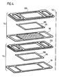
- eine schematische perspektivische Explosionsdarstellung zweier in einer Stapelrichtung aufeinanderfolgender Brennstoffzelleneinheiten des Brennstoffzellenblockverbunds aus Fig. 2;
- Fig. 5
- eine schematische Draufsicht auf eine Kontaktplatte einer der Brennstoffzelleneinheiten aus Fig. 4;
- Fig. 6
- eine schematische Draufsicht auf einen Fluidführungsrahmen einer der Brennstoffzelleneinheiten aus Fig. 4;
- Fig. 7
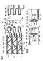
- den rechten Teil eines schematischen Längsschnitts durch drei längs der Stapelrichtung aufeinanderfolgende Brennstoffzelleneinheiten des Brennstoffzellenblockverbunds aus Fig. 2, wobei ein Fluidführungsrahmen einer Brennstoffzelleneinheit über eine Dichtung mit einem ringförmigen Dichtelement aus Keramik an der Kontaktplatte einer benachbarten Brennstoffzelleneinheit anliegt;
- Fig. 8
- einen schematischen Schnitt durch die Dichtung aus Fig. 7;
- Fig. 9
- eine ausschnittsweise Draufsicht auf einen gekrümmten Abschnitt der Dichtung aus Fig. 7;
- Fig. 10
- einen schematischen Schnitt durch eine zweite Ausführungsform der Dichtung;
- Fig. 11
- einen schematischen Schnitt durch eine dritte Ausführungsform der Dichtung;
- Fig. 12
- einen schematischen Schnitt durch eine vierte Ausführungsform der Dichtung;
- Fig. 13
- eine ausschnittsweise schematische Draufsicht auf eine Kontaktplatte mit mehreren Durchgangsöffnungen pro Gaskanal; und
- Fig. 14
- eine ausschnittsweise schematische Draufsicht auf einen Fluidführungsrahmen mit mehreren Durchgangsöffnungen pro Gaskanal.
- Fig. 1
- is a schematic perspective view of a fuel cell device;
- Fig. 2
- a schematic longitudinal section through a fuel cell block assembly arranged in the housing of the fuel cell device from FIG. 1;
- Fig. 3
- a schematic longitudinal section through a cathode-anode-electrolyte unit with adjoining contact plates;
- Fig. 4
- 2 shows a schematic perspective exploded view of two fuel cell units of the fuel cell block assembly from FIG. 2, which follow one another in a stacking direction;
- Fig. 5
- a schematic plan view of a contact plate of one of the fuel cell units from FIG. 4;
- Fig. 6
- a schematic plan view of a fluid guide frame of one of the fuel cell units from FIG. 4;
- Fig. 7
- the right part of a schematic longitudinal section through three successive along the stacking direction of the fuel cell units of the fuel cell block assembly of Figure 2, wherein a fluid guide frame of a fuel cell unit abuts a seal with an annular sealing element made of ceramic on the contact plate of an adjacent fuel cell unit.
- Fig. 8
- a schematic section through the seal of Fig. 7;
- Fig. 9
- a partial plan view of a curved portion of the seal of Fig. 7;
- Fig. 10
- a schematic section through a second embodiment of the seal;
- Fig. 11
- a schematic section through a third embodiment of the seal;
- Fig. 12
- a schematic section through a fourth embodiment of the seal;
- Fig. 13
- a fragmentary schematic plan view of a contact plate with a plurality of through openings per gas channel; and
- Fig. 14
- a fragmentary schematic plan view of a fluid guide frame with several through openings per gas channel.
Gleiche oder funktional äquivalente Elemente sind in allen Figuren mit denselben Bezugszeichen bezeichnet.The same or functionally equivalent elements are the same in all figures Reference numerals.
Eine in den Fig. 1 bis 9 dargestellte, als Ganzes mit 100 bezeichnete Brennstoffzellenvorrichtung
umfaßt ein im wesentlichen quaderförmiges Gehäuse
102 (siehe Fig. 1), in das eine Oxidationsmittel-Zuführleitung 104 mündet,
über die dem Innenraum des Gehäuses 102 ein Oxidationsmittel, beispielsweise
Luft oder reiner Sauerstoff, zugeführt wird.A fuel cell device shown in FIGS. 1 to 9, designated as a whole by 100
comprises a substantially cuboid housing
102 (see FIG. 1) into which an
Ferner mündet in das Gehäuse 102 eine Oxidationsmittel-Abführleitung 105,
durch welche überschüssiges Oxidationsmittel aus dem Innenraum des Gehäuses
102 abführbar ist.Furthermore, an
Im Innenraum des Gehäuses 102 ist ein in Fig. 2 als Ganzes dargestellter
Brennstoffzellenblockverbund 106 angeordnet, welcher eine untere Endplatte
108, eine obere Endplatte 110 und eine Vielzahl zwischen der unteren Endplatte
108 und der oberen Endplatte 110 angeordneter, längs einer Stapelrichtung
112 aufeinanderfolgender Brennstoffzelleneinheiten 114 umfaßt.In the interior of the
Wie am besten aus Fig. 4 zu ersehen ist, welche eine perspektivische Explosionsdarstellung
zweier längs der Stapelrichtung 112 aufeinanderfolgender
Brennstoffzelleneinheiten 114 zeigt, umfaßt jede der Brennstoffzelleneinheiten
114 eine im wesentlichen plattenförmige Kathoden-Anoden-Elektrolyt-Einheit
116 (im folgenden kurz: KAE-Einheit), die zwischen einer Kontaktplatte 118
und einem Fluidführungsrahmen 120 gehalten ist.As best seen in Fig. 4, which is an exploded perspective view
two in a row along the stacking
Die KAE-Einheit 116 umfaßt, wie in Fig. 3 rein schematisch dargestellt ist, eine
gasdurchlässige, elektrisch leitfähige Trägerschicht 121, die beispielsweise als
Netz aus einem metallischen Material ausgebildet sein kann, durch dessen Maschen
ein Brenngas aus einem an die Trägerschicht 121 angrenzenden Brenngasraum
124 hindurchtreten kann.The
Ferner umfaßt die KAE-Einheit 116 eine auf der Trägerschicht 121 angeordnete
plattenförmige Anode 122 aus einem elektrisch leitfähigen keramischen Material,
welches porös ist, um dem Brenngas aus dem Brenngasraum 124 den
Durchtritt durch die Anode 122 zu dem an die Anode 122 angrenzenden
Elektrolyten 126 zu ermöglichen.Furthermore, the
Als Brenngas kann ein kohlenwasserstoffhaltiges Gasgemisch oder reiner Wasserstoff verwendet werden.A hydrocarbon-containing gas mixture or pure hydrogen can be used as the fuel gas be used.
Der Elektrolyt 126 ist vorzugsweise als Feststoffelektrolyt ausgebildet.The
Auf der der Anode 122 gegenüberliegenden Seite des Elektrolyten 126 grenzt
an denselben eine plattenförmige Kathode 128 an, die aus einem elektrisch
leitfähigen keramischen Material gebildet ist und eine Porosität aufweist, um
einem Oxidationsmittel, beispielsweise Luft oder reinem Sauerstoff, aus einem
an die Kathode 128 angrenzenden Oxidationsmittelraum 130 den Durchtritt zu
dem Elektrolyten 126 zu ermöglichen.Bounded on the side of the
Im Betrieb der Brennstoffzellenvorrichtung 100 weist die KAE-Einheit 116 jeder
Brennstoffzelleneinheit 114 eine Temperatur von beispielsweise ungefähr
800°C auf, bei welcher der Elektrolyt 126 für Sauerstoffionen leitfähig ist. Das
Oxidationsmittel aus dem Oxidationsmittelraum 130 nimmt an der Anode 122
Elektronen auf und gibt zweiwertige Sauerstoffionen an den Elektrolyten 126
ab, welche durch den Elektrolyten 126 hindurch zur Anode 122 wandern. An
der Anode 122 wird das Brenngas aus dem Brenngasraum 124 durch die
Sauerstoffionen aus dem Elektrolyten 126 oxidiert und gibt dabei Elektronen
an die Anode 122 ab.In operation of the
Die Kontaktplatten 118 dienen dazu, die bei der Reaktion an der Anode 122
freiwerdenden Elektronen von der Anode 122 über die Trägerschicht 121
abzuführen bzw. die für die Reaktion an der Kathode 128 benötigten Elektronen
der Kathode 128 zuzuführen.The
Hierzu besteht jede der Kontaktplatten 118 aus einem elektrisch gut leitfähigen
Metallblech, das (wie am besten aus Fig. 5 zu ersehen ist) mit einer Vielzahl
von Kontaktelementen 132 versehen ist, welche beispielsweise die Form
von aneinander angrenzenden Vorsprüngen und Vertiefungen mit jeweils quadratischem
Grundriß aufweisen, so daß das aus den Kontaktelementen 132
gebildete Kontaktfeld 134 der Kontaktplatte 118 die Struktur eines in zwei zueinander
senkrechten Richtungen gewellten Wellblechs aufweist.For this purpose, each of the
Jedes der Kontaktelemente 132 weist einen mittigen Kontaktbereich 137 auf,
an dem es mit einer angrenzenden KAE-Einheit 116 in elektrisch leitendem
Kontakt steht.Each of the
Die kathodenseitigen Kontaktelemente 132b der Kontaktplatten 118 stehen
mit der Kathode 128 der einer benachbarten Brennstoffzelleneinheit 114 zugehörigen
KAE-Einheit 116 in elektrisch leitfähigem Punktkontakt, so daß Elektronen
von der Kontaktplatte 118 zu der Kathode 128 gelangen können. Auf
diese Weise ermöglichen die Kontaktplatten 118 den Ladungsausgleich zwischen
den Anoden 122 und Kathoden 128 längs der Stapelrichtung 112 aufeinanderfolgender
KAE-Einheiten 116.The cathode-
Die an den Enden des Brennstoffzellenblockverbunds 106 angeordneten Kontaktplatten
118 sind mit einem externen Stromkreislauf verbunden, um die an
diesen randständigen Kontaktplatten 118 entstehenden elektrischen Ladungen
abzugreifen. The contact plates arranged at the ends of the fuel
Wie am besten aus der Draufsicht der Fig. 5 zu ersehen ist, ist das mit den
Kontaktelementen 132 versehene mittige, rechteckige Kontaktfeld 134 jeder
Kontaktplatte 118 von einem ebenen Flanschbereich 136 umgeben, welchen
den äußeren Rand der Kontaktplatte 118 bildet.As can best be seen from the top view of FIG. 5, this is the case with the
Im Bereich der schmalen Längsseiten 138 des Flanschbereichs 136 liegt die
Unterseite der KAE-Einheit 116 auf der Oberseite des Flanschbereichs 136 auf.In the area of the narrow
Die breiten Seitenbereiche 140 des Flanschbereichs 136 weisen jeweils eine
Durchgangsöffnung 144 auf, welche den Durchtritt von den Brennstoffzelleneinheiten
114 zuzuführendem Brenngas bzw. von aus den Brennstoffzelleneinheiten
114 abzuführendem Abgas ermöglicht.The
Jede der Kontaktplatten 118 ist als Blechformteil ausgebildet, welches aus
einer im wesentlichen ebenen, im wesentlichen rechteckigen Blechlage durch
Prägen und/oder Tiefziehen sowie durch Ausstanzen oder Ausschneiden der
Durchgangsöffnungen 144 gebildet ist.Each of the
Auch die Fluidführungsrahmen 120 sind als Blechformteil aus einer im wesentlichen ebenen, im wesentlichen rechteckigen Blechlage gebildet.The fluid guide frames 120 are essentially made of a sheet metal part flat, essentially rectangular sheet metal layer is formed.
Wie am besten aus Fig. 6 zu ersehen ist, weist jeder Fluidführungsrahmen 120
an seinen Endbereichen den Durchgangsöffnungen 144 in den Kontaktplatten
entsprechende Durchgangsöffnungen, nämlich eine Brenngasdurchgangsöffnung
154 und eine Abgasdurchgangsöffnung 156, auf.As best seen in FIG. 6, each
Wie aus Fig. 6 zu ersehen ist, weist jeder der Fluidführungsrahmen 120 zwischen
den Durchgangsöffnungen 154, 156 eine im wesentlichen rechteckige,
mittige Durchtrittsöffnung 170 für den Durchtritt der Kontaktelemente 132 der
Kontaktplatte 118 einer benachbarten Brennstoffzelleneinheit 114 auf.As can be seen from FIG. 6, each of the fluid guide frames 120 has between
the through
Wie am besten aus den Fig. 6 und 7 zu ersehen ist, ist jede der Durchgangsöffnungen
154, 156 in einem Fluidführungsrahmen 120 von einem sich längs
der Stapelrichtung 112 erstreckenden Kragen 158, einem längs einer Biegelinie
160 an den Kragen 158 angrenzenden, sich senkrecht zur Stapelrichtung
112 von der Durchgangsöffnung weg erstreckenden Flanschbereich 162 und
einem an einer Biegelinie 164 an den Flanschbereich 162 angrenzenden, parallel
zur Stapelrichtung 112 ausgerichteten Kanalwandbereich 166 umgeben.As best seen in FIGS. 6 and 7, each of the through holes is
154, 156 in a
Wie aus den Fig. 7 und 8 zu ersehen ist, ist jede der Kontaktplatten 118 mit
einem Kragen 270 versehen, welcher durch Umbiegen der Flanschbereichs 136
längs einer Biegelinie 272 ausgebildet ist, sich parallel zu der Stapelrichtung
112 von dem Flanschbereich 136 aus nach unten erstreckt und die jeweilige
Durchgangsöffnung 144 der betreffenden Kontaktplatte 118 umgibt.As can be seen from FIGS. 7 and 8, each of the
Wie am besten aus Fig. 8 zu ersehen ist, sind die Kragen 270 und 158 einer
Kontaktplatte 118 bzw. eines derselben benachbarten Fluidführungsrahmens
120 miteinander fluchtend ausgerichtet und längs der Stapelrichtung 112 so
voneinander beabstandet, daß zwischen dem unteren Rand 274 des Kragens
270 und dem oberen Rand 276 des Kragens 158 ein Dichtspalt 278 verbleibt,
der mittels einer ringförmigen Gaskanal-Dichtung 188 mit Ringachse 283 abgedichtet
ist.As best seen in Figure 8,
Wie am besten aus Fig. 8 zu ersehen ist, umfaßt die Gaskanal-Dichtung 188
ein Dichtelement 280, das die Form einer ringförmig geschlossenen, eine Ring-Durchgangsöffnung
281 der Gaskanal-Dichtung 188 umgebenden Hülse aufweist.As best seen in FIG. 8,
Das Dichtelement 280 weist eine der Ring-Durchgangsöffnung 281 abgewandte
Außenseite 282 auf, an deren oberem Bereich die Außenseite des Kragens
270 der Kontaktplatte 118 flächig anliegt und an deren unterem Bereich
die Außenseite des Kragens 158 des Fluidführungsrahmens 120 flächig anliegt.The sealing
Ferner weist das Dichtelement 280 an seiner Außenseite 282 einen längs des
Umfangs des Dichtelements 280 umlaufenden Vorsprung 284 auf, welcher sich
in den Dichtspalt 278 hineinerstreckt und so den unteren Rand 274 des Kragens
270 von dem oberen Rand 276 des Kragens 158 trennt.Furthermore, the sealing
Wie aus der Draufsicht auf die Gaskanal-Dichtung 188 in Fig. 9 zu ersehen ist,
weist das Dichtelement 280 in den Eckbereichen der Durchgangsöffnungen
144, 156 jeweils einen gekrümmten Abschnitt 285 auf, in welchem die Außenseite
282 des Dichtelement 280 konvex gekrümmt ist und die der Ring-Durchgangsöffnung
281 zugewandte Innenseite 286 des Dichtelements 280 konkav
gekrümmt ist.As can be seen from the top view of the
Das Dichtelement 280 ist aus einem keramischen Material gebildet, welches
auch bei der Betriebstemperatur der Brennstoffzellenvorrichtung 100 von beispielsweise
800°C fest und formstabil ist und einen hohen elektrischen Widerstand
aufweist.The sealing
Als keramisches Material für das Dichtelement 280 kann beispielsweise ein
Magnesium-Silikat, insbesondere Forsterit (Bezeichnung nach DIN EN 60672:
C250) verwendet werden. Forsterit weist im Temperaturbereich von 20°C bis
600°C einen mittleren linearen Wärmeausdehnungskoeffizienten α von ungefähr
10 · 10-6 K-1 bis ungefähr 11 · 10-6 K-1 auf. Der spezifische elektrische Widerstand
von Forsterit liegt bei einer Temperatur von 600°C bei ungefähr 105
Ωm.For example, a magnesium silicate, in particular forsterite (designation according to DIN EN 60672: C250) can be used as the ceramic material for the sealing
Dieses Material kann beispielsweise von der Firma Sembach Technische Keramik, Oskar-Sembach-Straße 15, 91207 Lauff an der Pegnitz, Deutschland, bezogen werden.This material can be obtained, for example, from Sembach Technische Keramik, Oskar-Sembach-Strasse 15, 91207 Lauff an der Pegnitz, Germany become.
Alternativ oder ergänzend hierzu kann als keramisches Material für das Dichtelement
280 auch ein Aluminiumoxid, insbesondere das nach DIN EN 60672
mit C799 bezeichnete Aluminiumoxid, verwendet werden. Das Aluminiumoxid
C799 weist im Bereich von 20°C bis 600°C einen mittleren linearen Ausdehnungskoeffizienten
α von ungefähr 7 · 10-6 K-1 bis ungefähr 8 · 10-6 K-1 auf. Der
spezifische elektrische Widerstand dieses Materials beträgt bei einer Temperatur
von 600°C ungefähr 106 Ωm.As an alternative or in addition to this, an aluminum oxide, in particular the aluminum oxide designated C799 according to DIN EN 60672, can also be used as the ceramic material for the sealing
Dieses Material kann beispielsweise unter der Bezeichnung "A99" von der vorstehend genannten Firma Sembach Technische Keramik bezogen werden.This material can, for example, under the designation "A99" from the above Sembach Technical Ceramics.
Alternativ oder ergänzend zu den vorstehend genannten Materialien kann als
keramisches Material für das Dichtelement 280 auch ein Zirkonoxid, insbesondere
ein durch die Beimengung kleiner Mengen von Yttriumoxid zur Stabilisierung
der Kristallstruktur teilstabilisiertes Zirkonoxid, verwendet werden.As an alternative or in addition to the materials mentioned above, as
ceramic material for the sealing
Das teilstabilisierte Zirkonoxid weist im Temperaturbereich von 30°C bis 1000°C einen mittleren linearen Wärmeausdehnungskoeffizienten α von ungefähr 10 · 10-6 K-1 bis ungefähr 12,5 · 10-6 K-1 auf. Der spezifische elektrische Widerstand dieses Materials beträgt bei einer Temperatur von 600°C ungefähr 103 Ωm bis ungefähr 106 Ωm.The partially stabilized zirconium oxide has in the temperature range from 30 ° C. to 1000 ° C. an average linear coefficient of thermal expansion α of approximately 10 · 10 -6 K -1 to approximately 12.5 · 10 -6 K -1 . The specific electrical resistance of this material is about 10 3 Ωm to about 10 6 Ωm at a temperature of 600 ° C.
Das Dichtelement 280 kann aus den vorstehend genannten keramischen Materialien
beispielsweise durch keramisches Spritzgießen hergestellt werden. Bei
diesem Verfahren wird ein keramisches Pulver aus dem gewünschten Material
mit einem organischen Bindersystem plastifiziert und auf einer Kunststoffhochdruckspritzgußmaschine
verarbeitet. Nach der Formgebung wird das organische
Bindemittel entfernt. Anschließend wird das durch Spritzgießen hergestellte
Formteil gesintert und erforderlichenfalls nachbearbeitet.The sealing
Das Dichtelement 280 sitzt in Preßpassung in dem Kragen 270 der Kontaktplatte
118 und in dem Kragen 158 des Fluidführungsrahmens 120, wobei das
Dichtelement 280 durch den Kragen 270 und den Kragen 158 mit einer zur
Ringachse 283 des Dichtelements 280 gerichteten Druckspannung beaufschlagt
wird.The sealing
Der Preßsitz des Dichtelements 280 in den Kragen 270 und 158 wird erzielt,
indem bei der Montage der Brennstoffzellenvorrichtung 100 der Flanschbereich
136 der Kontaktplatte 118 und der Fluidführungsrahmen 120 auf eine erhöhte
Temperatur von beispielsweise 300°C erwärmt werden, um die Durchgangsöffnungen
144 bzw. 154, 156, die von dem Kragen 270 bzw. 158 umgeben sind,
zu vergrößern. In die solchermaßen durch Wärmedehnung erweiterten Kragen
270 und 158 wird das kältere Dichtelement 280, welches beispielsweise
Raumtemperatur (20°C) aufweist, eingesetzt. Bei der anschließenden Abkühlung
der Kontaktplatte 118 und des Fluidführungsrahmens 120 schrumpfen
dann die Kragen 270 und 158 auf die Außenseite 282 des Dichtelements 280
auf, wodurch das Dichtelement 280 bereits bei Raumtemperatur mit einer
Druckspannung beaufschlagt wird.The press fit of the sealing
Dadurch, daß die Außenseiten der Kragen 270 und 158 flächig gegen die
Außenseite 282 des Dichtelements 280 gepreßt werden, ist eine zuverlässige,
gasdichte und elektrisch isolierende Abdichtung des von dem Dichtelement
280 überdeckten Dichtspalts 278 gewährleistet.Characterized in that the outer sides of the
Der Flanschbereich 136 der Kontaktplatte 118 und der Fluidführungsrahmen
120 werden vorzugsweise aus einem hitzebeständigen Stahl hergestellt.The
Beispielsweise kann als Material für diese Bauelemente ein ferritischer Stahl mit der Werkstoffnummer 1.4742 (nach SEW 470) verwendet werden, welcher folgende Zusammensetzung aufweist:For example, a ferritic steel can be used as the material for these components with the material number 1.4742 (according to SEW 470), which has the following composition:
0,08 Gewichts-% Kohlenstoff, 1,3 Gewichts-% Silizium, 0,7 Gewichts-% Mangan,
18 Gewichts-% Chrom, 1 Gewichts-% Aluminium, Rest Eisen. Ein solcher
Stahl weist eine gute Temperaturbeständigkeit bis zu einer Temperatur von
1000°C auf. Der mittlere lineare Wärmeausdehnungskoeffizient dieses Materials
zwischen 20°C und 600°C beträgt ungefähr 12 · 10-6 K-1 und ist somit
ungefähr gleich groß wie der mittlere lineare Wärmeausdehnungskoeffizient
von teilstabilisiertem Zirkonoxid in diesem Temperaturbereich. Wird das Dichtelement
280 aus teilstabilisierten Zirkonoxid und die Kontaktplatte 118 und
der Fluidführungsrahmen aus dem Stahl 1.4742 hergestellt, so dehnen sich
das Dichtelement 280 und die Kragen 270 sowie 158 beider Erwärmung der
Brennstoffzellenvorrichtung von Raumtemperatur auf die Betriebstemperatur
von ungefähr 800°C im wesentlichen gleich stark aus, so daß die bei Raumtemperatur
bestehende Vorspannung des Dichtelements 280 durch die Kragen
270 und 158 auch bei der Betriebstemperatur der Gaskanal-Dichtung 188 im
wesentlichen unverändert bleibt, so daß ein hoher Anpressdruck der Außenseiten
der Kragen 270, 158 gegen die Außenseite des Dichtelements 280 und
somit eine Gasdichtheit der Gaskanal-Dichtung 188 gewährleistet ist.0.08% by weight carbon, 1.3% by weight silicon, 0.7% by weight manganese, 18% by weight chromium, 1% by weight aluminum, balance iron. Such a steel has good temperature resistance up to a temperature of 1000 ° C. The average linear thermal expansion coefficient of this material between 20 ° C and 600 ° C is approximately 12 · 10 -6 K -1 and is therefore approximately the same size as the average linear thermal expansion coefficient of partially stabilized zirconium oxide in this temperature range. If the sealing
Werden statt des teilstabilisierten Zirkonoxids Forsterit oder Aluminiumoxid
C799 verwendet, so ist der mittlere lineare Wärmeausdehnungskoeffizient des
Dichtelements 280 kleiner als der mittlere lineare Wärmeausdehnungskoeffizient
der Kragen 158, 270. In diesem Fall dehnen sich die Kragen 270, 158 bei
der Erwärmung auf die Betriebstemperatur stärker aus als das Dichtelement
280, so daß die auf das Dichtelement 280 wirkende Druckspannung im Betriebszustand
der Gaskanal-Dichtung 188 geringer ist als bei Raumtemperatur.
Die auf das Dichtelement 280 bei Raumtemperatur wirkende Druck-Vorspannung
wird jedoch in diesem Fall so groß gewählt, daß auch nach einer Verringerung
der Druckspannung durch die unterschiedliche Wärmedehnung von
Dichtelement 280 und Kragen 270, 158 der Anpreßdruck, mit dem die Außenseiten
der Kragen 270, 158 bei Betriebstemperatur gegen die Außenseite 282
des Dichtelements 280 gedrückt werden, noch ausreichend hoch ist, um die
erforderliche Gasdichtheit der Gaskanal-Dichtung 188 sicherzustellen.Are instead of the partially stabilized zirconium oxide forsterite or aluminum oxide
C799 is used, the mean linear coefficient of thermal expansion is
Sealing
Wird das Dichtelement 280 aus einem keramischen Material gebildet, welches
einen höheren mittleren linearen Wärmeausdehnungskoeffizienten aufweist als
das Material der Kragen 270, 158, so nimmt die auf das Dichtelement 280 wirkende
Druckspannung beim Erwärmen auf die Betriebstemperatur sogar noch
zu.The sealing
In diesem Fall können die Kragen 270, 158 bei Raumtemperatur druckfrei an
dem Dichtelement anliegen oder sogar von demselben beabstandet sein. Bei
der Erwärmung auf die Betriebstemperatur dehnt sich dann das Dichtelement
280 stärker aus als die Kragen 270, 158, so daß die Außenseiten der Kragen
270, 158 mit dem für eine gute Gasdichtheit erforderlichen Anpreßdruck gegen
die Außenseite 282 des Dichtelements 280 gepreßt werden.In this case, the
In diesem Fall brauchen die Kragen 270, 158 bei der Herstellung der Brennstoffzellenvorrichtung
100 nicht auf das Dichtelement 280 aufgeschrumpft zu
werden; vielmehr genügt es, das Dichtelement 280 in die Kragen 270, 158
einzusetzen.In this case, the
Wie am besten aus den Fig. 4 und 7 zu ersehen ist, ist jede KAE-Einheit 116
am Rand ihrer dem Fluidführungsrahmen 120 derselben Brennstoffzelleneinheit
114 zugewandten Oberseite mit einer gasdichten, elektrisch isolierenden
Brenngasraum-Dichtung 186 versehen, die seitlich über die KAE-Einheit 116
übersteht.As best seen in FIGS. 4 and 7, each KAE unit is 116
on the edge of the same
Diese Brenngasraum-Dichtung 186 kann beispielsweise eine Flachdichtung aus
Glimmer umfassen.This fuel
Insbesondere kann diese Flachdichtung Spaltglimmer, vorzugsweise Phlogopit, oder ein auf einer Papiermaschine hergestelltes Glimmerpapier umfassen.In particular, this flat seal can be mica, preferably phlogopite, or include mica paper made on a paper machine.
Die Brennstoffzelleneinheiten 114 des Brennstoffzellenblockverbunds 106 sind
längs der Stapelrichtung 112 so aufeinandergestapelt, daß die kathodenseitigen
Kontaktelemente 132b jeder Kontaktplatte 118 sich durch die Durchtrittsöffnung
170 im Fluidführungsrahmen 120 der jeweils darunter angeordneten
Brennstoffzelleneinheit 114 zu der Kathode der KAE-Einheit 116 der darunter
angeordneten Brennstoffzelleneinheit 114 erstrecken und in elektrisch leitendem
Kontakt an derselben anliegen. The
Der Kragen 270 des Flanschbereichs 270 jeder Kontaktplatte 118 liegt dabei
über die Gaskanal-Dichtung 188 an dem Kragen 158 des Fluidführungsrahmens
120 der jeweils darunter angeordneten Brennstoffzelleneinheit 114 an.The
Der die Brenngasdurchgangsöffnung 154 umgebende Endbereich 152 jedes
Fluidführungsrahmens 120 bildet einen Brenngasführungsbereich. Der die Abgasdurchgangsöffnung
156 umgebende Endbereich 152 jedes Fluidführungsrahmens
120 bildet einen Abgasführungsbereich.The
Wie am besten aus der Schnittdarstellung der Fig. 2 zu ersehen ist, bilden die
längs der Stapelrichtung 112 aufeinanderfolgenden Brenngasführungsbereiche
der Fluidführungsrahmen 120 zusammen einen sich parallel zur Stapelrichtung
112 erstreckenden Brenngaskanal 190, der an seinem oberen Ende in einer
Ausnehmung 192 an der Unterseite der oberen Endplatte 110 mündet.As can best be seen from the sectional view of FIG. 2, the
along the stacking
An dem unteren Ende des Brenngaskanals 190 mündet in denselben eine
Brenngaszuführöffnung 194, welche die untere Endplatte 108 des Brennstoffzellenblockverbunds
106 koaxial zu dem Brenngaskanal 190 durchsetzt.At the lower end of the
An das dem Brenngaskanal 190 abgewandte Ende der Brenngaszuführöffnung
194 ist eine Brenngaszuführleitung 196 angeschlossen, welche durch das Gehäuse
102 der Brennstoffzellenvorrichtung 100 gasdicht hindurchgeführt und
an eine (nicht dargestellte) Brenngaszufuhr angeschlossen ist, welche der
Brenngaszuführleitung 196 ein Brenngas, beispielsweise ein kohlenwasserstoffhaltiges
Gas oder reinen Wasserstoff, zuführt.At the end of the fuel gas supply opening facing away from the
Wie ebenfalls aus Fig. 2 zu ersehen ist, bilden die Abgasführungsbereiche der
längs der Stapelrichtung 112 aufeinanderfolgenden Fluidführungsrahmen 120
zusammen einen Abgaskanal 198, der parallel zu der Stapelrichtung 112 ausgerichtet
ist und an seinem unteren Ende durch einen an der Oberseite der
unteren Endplatte 108 des Brennstoffzellenblockverbunds 106 vorgesehenen
Vorsprung 200 verschlossen ist.As can also be seen from FIG. 2, the exhaust gas routing areas form the
along the stacking
An seinem oberen Ende mündet der Abgaskanal 198 in eine zu demselben
koaxiale Abgasabführöffnung 202, welche die obere Endplatte 110 des Brennstoffzellenblockverbunds
106 durchsetzt und an ihrem dem Abgaskanal 198
abgewandten Ende an eine Abgasabführleitung 204 angeschlossen ist.At its upper end, the
Die Abgasabführleitung 204 ist gasdicht durch das Gehäuse 102 der Brennstoffzellenvorrichtung
100 hindurchgeführt und an eine (nicht dargestellte)
Abgasbehandlungseinheit angeschlossen.The exhaust
Im Betrieb der Brennstoffzellenvorrichtung 100 strömt das Brenngas durch die
Brenngaszuführleitung 196 und die Brenngaszuführöffnung 194 in den Brenngaskanal
190 ein und verteilt sich von dort durch die Zwischenräume zwischen
den Kontaktplatten 118 und den jeweils derselben Brennstoffzelleneinheit 114
zugehörigen Fluidführungsrahmen 120 auf die Brenngasräume 124 der Brennstoffzelleneinheiten
114, welche jeweils durch die Kontaktplatte 118, den
Fluidführungsrahmen 120 und die KAE-Einheit 116 der betreffenden Brennstoffzelleneinheit
116 der betreffenden Brennstoffzelleneinheit 114 umschlossen
sind.During operation of the
Das Brenngas wird zumindest teilweise an der Anode 122 der jeweiligen KAE-Einheit
116 oxidiert. The fuel gas is at least partially at the
Das Oxidationsprodukt (beispielsweise Wasser) gelangt zusammen mit überschüssigem
Brenngas aus den Brenngasräumen 124 der Brennstoffzelleneinheiten
114 in den Abgaskanal 198, aus welchem es durch die Abgasabführöffnung
202 und die Abgasabführleitung 204 zu der Abgasbehandlungseinheit
abgeführt wird.The oxidation product (e.g. water) comes together with excess
Fuel gas from the
Das für den Betrieb der Brennstoffzellenvorrichtung 100 benötigte Oxidationsmittel
(beispielsweise Luft oder reiner Sauerstoff) wird dem Innenraum des
Gehäuses 102 durch die Oxidationsmittel-Zuführleitung 104 zugeführt.The oxidizing agent required to operate the fuel cell device 100
(for example air or pure oxygen) becomes the interior of the
Im Innenraum des Gehäuses 102 verteilt sich das Oxidationsmittel auf die zwischen
den Brenngasräumen 124 der Brennstoffzelleneinheiten 114 ausgebildeten
Oxidationsmittelräume 130, welche durch jeweils eine Kontaktplatte 118
einer Brennstoffzelleneinheit 114 sowie durch den Fluidführungsrahmen 120
und die Kathode 128 der KAE-Einheit 116 einer benachbarten Brennstoffzelleneinheit
114 umschlossen sind.In the interior of the
In die Oxidationsmittelräume hinein und aus denselben wieder heraus gelangt
das Oxidationsmittel durch die Zwischenräume zwischen jeweils einem Fluidführungsrahmen
120 einer Brennstoffzelleneinheit 114 und der Kontaktplatte
118 der in der Stapelrichtung 112 darauffolgenden Brennstoffzelleneinheit 114.Into and out of the oxidant spaces
the oxidizing agent through the spaces between a respective
Überschüssiges Oxidationsmittel gelangt aus den Oxidationsmittelräumen 130
der Brennstoffzelleneinheiten 114 auf der der Eintrittsseite des Oxidationsmittels
gegenüberliegenden Austrittsseite hinaus und wird durch die Oxidationsmittel-Abführleitung
105 aus dem Innenraum des Gehäuses 102 der Brennstoffzellenvorrichtung
100 abgeführt. Excess oxidant comes out of the
Die Strömungsrichtung des Brenngases und des Abgases durch die Brennstoffzellenvorrichtung
100 ist in den Zeichnungen mit einfachen Pfeilen 210, die
Strömungsrichtung des Oxidationsmittels durch die Brennstoffzellenvorrichtung
100 mittels Doppelpfeilen 212 angegeben.The flow direction of the fuel gas and the exhaust gas through the
Um die längs der Stapelrichtung 112 aufeinanderfolgenden Brennstoffzelleneinheiten
114 durch äußere Verspannung aneinander festzulegen, sind mehrere
Verbindungsschrauben 214 vorgesehen, welche Durchgangsbohrungen
216 in den Endplatten 108, 110 des Brennstoffzellenblockverbunds 106 durchsetzen
und an ihrem dem jeweiligen Schraubenkopf 218 abgewandten Ende
mit einem Außengewinde 220 versehen sind, in welches jeweils eine Verbindungsmutter
222 eingedreht ist, so daß die Endplatten 108, 110 zwischen den
Schraubenköpfen 218 und den Verbindungsmuttern 222 eingespannt sind und
eine gewünschte Preßkraft über die Endplatten 108, 110 auf den Stapel der
Brennstoffzelleneinheiten 114 übertragbar ist (siehe Fig. 2).The fuel cell units consecutive along the stacking
Der vorstehend beschriebene Brennstoffzellenblockverbund 106 wird wie folgt
montiert:
Dann wird der Brennstoffzellenblockverbund 106 aus den einzelnen Brennstoffzelleneinheiten
114 zusammengesetzt, indem die gewünschte Anzahl von
Brennstoffzelleneinheiten 114 längs der Stapelrichtung 112 gestapelt wird und
jeweils ein Kragen 270 einer Kontaktplatte 118 mit dem Kragen 158 des
Fluidführungsrahmens 120 einer benachbarten Brennstoffzelleneinheit 114
mittels eines in Preßpassung in diesen Kragen sitzenden Dichtelements 280
verbunden wird.The fuel
Schließlich werden die Brennstoffzelleneinheiten 114 mittels der Endplatten
108, 110 und der die Endplatten gegeneinander verspannenden Verbindungsschrauben
214 und Verbindungsmuttern 222 gegeneinander verspannt.Finally, the
Eine in Fig. 10 dargestellte zweite Ausführungsform einer Brennstoffzellenvorrichtung 100 unterscheidet sich von der vorstehend beschriebenen ersten Ausführungsform lediglich durch die Ausgestaltung der Gaskanal-Dichtung 188.A second embodiment of a fuel cell device shown in FIG. 10 100 differs from the first described above Embodiment only through the design of the gas channel seal 188th
Wie aus Fig. 10 zu ersehen ist, weist das Dichtelement 280' bei dieser zweiten
Ausführungsform keinen an der Außenseite 282 umlaufenden Vorsprung auf;
vielmehr ist die Außenseite 282 des Dichtelements 280 durchgehend eben
ausgebildet.As can be seen from FIG. 10, the sealing
Gleichwohl bleibt die erforderliche elektrische Isolationswirkung der Gaskanal-Dichtung
188 erhalten, da der untere Rand 274 des Kragens 270 an der Kontaktplatte
118 und der obere Rand 276 des Kragens 158 an dem Fluidführungsrahmen
120 durch den Dichtspalt 278 voneinander getrennt sind. Aufgrund
der hohen Reibung zwischen den Außenseiten der Kragen 270, 158
einerseits und der Außenseite 282 des Dichtelements 280' andererseits, die
durch die hohe Pressung zwischen diesen Bauelementen hervorgerufen wird,
ist gewährleistet, daß sich die beiden Kragen 270, 158 nicht relativ zu dem
Dichtelement 280' und somit nicht aufeinander zu bewegen. Nevertheless, the required electrical insulation effect of the gas channel seal remains
188 received because the
Durch das Fehlen des Vorsprungs an der Außenseite 282 des Dichtelements
280' ist das Dichtelement 280' der zweiten Ausführungsform einfacher herstellbar
und leichter nacharbeitbar als das Dichtelement 280 der ersten Ausführungsform.Due to the lack of the protrusion on the outside 282 of the sealing element
280 ', the sealing element 280' of the second embodiment is easier to manufacture
and easier to rework than the sealing
Im übrigen stimmt die zweite Ausführungsform einer Brennstoffzellenvorrichtung 100 hinsichtlich Aufbau und Funktion mit der ersten Ausführungsform überein, auf deren vorstehende Beschreibung insoweit Bezug genommen wird.Otherwise, the second embodiment of a fuel cell device is correct 100 in structure and function with the first embodiment agree, to the above description of which reference is made.
Eine in Fig. 11 dargestellte dritte Ausführungsform einer Brennstoffzellenvorrichtung 100 unterscheidet sich von der vorstehend beschriebenen ersten Ausführungsform lediglich hinsichtlich der Ausgestaltung der Gaskanal-Dichtung 188.A third embodiment of a fuel cell device shown in FIG. 11 100 differs from the first described above Embodiment only with regard to the design of the gas channel seal 188th
Wie aus Fig. 11 zu ersehen ist, liegen die Kragen 270, 158 bei dieser Ausführungsform
nicht mit ihren Außenseiten an der Außenseite 282 des Dichtelements
der Gaskanal-Dichtung 188, sondern vielmehr mit ihren Innenseiten an
der Innenseite 286 des als ringförmig geschlossene Hülse aus einem keramischen
Material ausgebildeten Dichtelements 280' an.As can be seen from FIG. 11, the
Bei dieser Konfiguration der Gaskanal-Flachdichtung 188 würde das Dichtelement
280' durch die Kragen 270, 158 also nicht auf Druck, sondern auf Zug
beansprucht, was für ein keramisches Material ungünstig ist.With this configuration of the gas channel
Diese Zugbeanspruchung des Dichtelements 280 wird daher durch eine Druckbeanspruchung
ausgeglichen oder überkompensiert, welche mittels einer das
Dichtelement 280' ringförmig umgebenden, mit ihrer Innenseite flächig an der This tensile stress of the sealing
Außenseite 282 des Dichtelements 280' anliegenden Spannhülse 288 erzeugt
wird.Outside 282 of the sealing element 280 '
Die Spannhülse 288 wird beispielsweise aus einem Stahl gebildet, welcher bei
der Betriebstemperatur der Brennstoffzellenvorrichtung von ungefähr 800°C
beständig ist.The clamping
Die erforderliche Druckspannungsbeaufschlagung des Dichtelements 280'
durch die Spannhülse 288 wird erreicht, indem die Spannhülse 288 bei der
Herstellung der Gaskanal-Flachdichtung 188 auf das Dichtelement 280' aufgeschrumpft
wird und/oder indem ein Material für die Spannhülse 288 verwendet
wird, welches einen kleineren mittleren linearen Wärmeausdehnungskoeffizienten
aufweist als das Material des Dichtelements 280'.The required compressive stressing of the sealing element 280 '
through the clamping
Das Material der Kragen 270, 158 sollte bei dieser Ausführungsform einen
mittleren linearen Wärmeausdehnungskoeffizienten aufweisen, welcher mindestens
gleich groß oder nur geringfügig kleiner ist als der mittlere lineare Wärmeausdehnungskoeffizient
des Materials des Dichtelements 280', um beim Erwärmen
der Gaskanal-Dichtung 188 auf die Betriebstemperatur das Entstehen
eines Spaltes zwischen den Innenseiten der Kragen 270, 158 einerseits und
der Innenseite 286 des Dichtelements 280' andererseits zu verhindern.The material of the
Das Dichtelement 280' der dritten Ausführungsform weist ebenso wie das Dichtelement 280' der zweiten Ausführungsform keinen an der Außenseite umlaufenden Vorsprung auf.The sealing member 280 'of the third embodiment has the same as that Sealing element 280 'of the second embodiment does not have any on the outside circumferential lead.
Im übrigen stimmt die dritte Ausführungsform einer Brennstoffzellenvorrichtung 100 hinsichtlich Aufbau und Funktion mit der ersten Ausführungsform überein, auf deren vorstehende Beschreibung insoweit Bezug genommen wird. Otherwise, the third embodiment of a fuel cell device is correct 100 in structure and function with the first embodiment agree, to the above description of which reference is made.
Eine in Fig. 12 dargestellte vierte Ausführungsform einer Brennstoffzellenvorrichtung 100 unterscheidet sich von der vorstehend beschriebenen ersten Ausführungsform lediglich durch die Ausgestaltung der Gaskanal-Dichtung 188.A fourth embodiment of a fuel cell device shown in FIG. 12 100 differs from the first described above Embodiment only through the design of the gas channel seal 188th
Wie aus Fig. 12 zu ersehen ist, liegt bei dieser Ausführungsform nur der Kragen
270 der Kontaktplatte 118 mit seiner Außenseite an der Außenseite 282
des Dichtelements 280' an; der Kragen 158 des Fluidführungsrahmens 120
greift hingegen von der Unterseite her in die Ring-Durchgangsöffnung 281 des
Dichtelements 280' ein und liegt mit seiner Innenseite flächig an der Innenseite
286 des Dichtelements 280' an.As can be seen from FIG. 12, only the collar lies in this
Bei dieser Ausführungsform wird das Dichtelement 280' durch den Kragen 158
an dem Fluidführungsrahmen auf Zug und durch den Kragen 270 an der Kontaktplatte
118 auf Druck beansprucht.In this embodiment, the sealing element 280 'is through the
Dabei werden die Geometrie der beteiligten Bauteile und deren Wärmeausdehnungskoeffizienten
so gewählt, daß die Druckbeanspruchung durch den Kragen
270 an der Kontaktplatte 118 die Zugbeanspruchung durch den Kragen 159 an
dem Fluidführungsrahmen 120 übertrifft.The geometry of the components involved and their thermal expansion coefficients
chosen so that the pressure load through the
Insbesondere kann vorgesehen sein, daß der Kragen 270 an der Kontaktplatte
118 bei der Herstellung der Gaskanal-Dichtung 188 auf die Außenseite 282 des
Dichtelements 280' aufgeschrumpft wird.In particular, it can be provided that the
Ferner ist es von Vorteil, wenn der Flanschbereich 136 der Kontaktplatte 118
aus einem Material gebildet ist, welches einen kleineren mittleren linearen
Wärmeausdehnungskoeffizienten aufweist als das Material des Dichtelements
280'.It is also advantageous if the
Als Material für den Fluidführungsrahmen 120 wird vorzugsweise ein Material
gewählt, dessen mittlerer linearer Wärmeausdehnungskoeffizient mindestens
gleich groß ist wie oder nur geringfügig kleiner ist als der mittlere lineare
Wärmeausdehnungskoeffizient des Materials des Dichtelements 280', um zu
verhindern, daß sich bei der Erwärmung der Gaskanal-Dichtung 188 auf die
Betriebstemperatur zwischen der Innenseite 286 des Dichtelements 280' und
der Innenseite des Kragens 158 an dem Fluidführungsrahmen 120 ein Spalt
ausbildet.A material is preferably used as the material for the
Die Ring-Durchgangsöffnung 281 wird von der Seite her mit Brenngas bzw.
Abgas durchströmt, von welcher der an der Innenseite 286 des Dichtelements
280' anliegende Kragen 158 in das Dichtelement 280' eingreift. Dadurch werden
die Anlageflächen, an denen der Kragen 158 bzw. der Kragen 270 an dem
Dichtelement 280' anliegen, nicht direkt von dem Gas angeströmt, was den
Gasdurchtritt durch die Gaskanal-Dichtung 188 im Falle eventuell auftretender
Undichtigkeiten verringert.The
Das Dichtelement 280' der vierten Ausführungsform weist ebenso wie die Dichtelemente 280' der zweiten und der dritten Ausführungsform keinen längs seiner Außenseite 282 umlaufenden Vorsprung auf.The sealing member 280 'of the fourth embodiment has the same as that Sealing elements 280 'of the second and third embodiments are not longitudinal its outside 282 circumferential projection.
Im übrigen stimmt die vierte Ausführungsform einer Brennstoffzellenvorrichtung 100 hinsichtlich Aufbau und Funktion mit der ersten Ausführungsform überein, auf deren vorstehende Beschreibung insoweit Bezug genommen wird. Otherwise, the fourth embodiment of a fuel cell device is correct 100 in structure and function with the first embodiment agree, to the above description of which reference is made.
Eine in den Fig. 13 und 14 dargestellte fünfte Ausführungsform einer Brennstoffzellenvorrichtung
100 unterscheidet sich von den vorstehend beschriebenen
Ausführungsformen lediglich dadurch, daß jeder Seitenbereich 140 des
Flanschbereichs 136 einer Kontaktplatte 118 nicht lediglich eine Durchgangsöffnung
144, sondern statt dessen mehrere, beispielsweise drei, kleinere
Durchgangsöffnungen 144' aufweist (siehe Fig. 13).A fifth embodiment of a fuel cell device shown in FIGS. 13 and 14
100 differs from those described above
Embodiments only in that each
In entsprechender Weise weist jeder Fluidführungsrahmen 120 an seinen Endbereichen
mehrere, beispielsweise drei, den Durchgangsöffnungen 144' in den
Kontaktplatten entsprechende Brenngasdurchgangsöffnungen und Abgasdurchgangsöffnungen
156' auf.In a corresponding manner, each
Jede der Durchgangsöffnungen in den Fluidführungsrahmen 120 ist in der vorstehend
beschriebenen Weise mit einem zu einer benachbarten Kontaktplatte
118 hin weisenden Kragen 158 versehen.Each of the through holes in the
Jede der Durchgangsöffnungen 144' in den Kontaktplatten 118 ist in der vorstehend
beschriebenen Weise mit einem zu einem benachbarten Fluidführungsrahmen
120 hin gerichteten Kragen 270 versehen.Each of the through holes 144 'in the
Jeweils ein Kragen 270 einer Kontaktplatte 118 und ein Kragen 158 eines
Fluidführungsrahmens 120 sind in der vorstehend beschriebenen Weise über
eine Gaskanal-Dichtung 188 gasdicht und elektrisch isolierend miteinander
verbunden.One
Diese Gaskanal-Dichtungen können in jeder vorstehend beschriebenen Weise ausgebildet sein. These gas channel seals can be in any of the ways described above be trained.
Da die Durchgangsöffnungen 144', 156' bei der fünften Ausführungsform jedoch
(bei gleicher Gesamt-Gasdurchtrittsfläche) kleiner sind als die entsprechenden
Durchgangsöffnungen bei der ersten bis vierten Ausführungsform,
können die Dichtelemente 280, 280' der Gaskanal-Dichtungen 188 bei der
fünften Ausführungsform kleiner, insbesondere mit kürzerer Umfangslänge,
ausgebildet werden als bei den anderen Ausführungsformen.However, since the through holes 144 ', 156' in the fifth embodiment
(with the same total gas passage area) are smaller than the corresponding ones
Through holes in the first to fourth embodiments,
can the sealing
Dies erleichtert die Herstellung dieser Dichtelemente und verringert die Gefahr einer Rißbildung oder gar eines Bruches des Dichtelements.This facilitates the manufacture of these sealing elements and reduces the risk a cracking or even a breakage of the sealing element.
Im übrigen stimmt die fünfte Ausführungsform einer Brennstoffzellenvorrichtung 100 hinsichtlich Aufbau und Funktion mit den zuvor beschriebenen Ausführungsformen überein, auf deren vorstehende Beschreibung insoweit Bezug genommen wird.Otherwise, the fifth embodiment of a fuel cell device is correct 100 in terms of structure and function with the previously described embodiments agree, to the above description of which reference is taken.
Claims (27)
dadurch gekennzeichnet, daß die Dichtung (188) mindestens ein Dichtelement (280; 280') umfaßt, welches ein keramisches Material umfaßt, wobei die Dichtung (188) ringförmig ausgebildet ist und mindestens eine Anlagefläche für mindestens eines der abzudichtenden Bauteile (118, 120) aufweist, welche zumindest teilweise im wesentlichen parallel oder schräg zur Ringachse (283) der Dichtung (188) ausgerichtet ist.Seal for sealing a sealing gap (278) between two electrically conductive components (118, 120) to be sealed, in particular between two components of a fuel cell block assembly (106), with electrical insulation of the components (118, 120) to be sealed,
characterized in that the seal (188) comprises at least one sealing element (280; 280 '), which comprises a ceramic material, the seal (188) being annular and at least one contact surface for at least one of the components (118, 120) to be sealed which is at least partially aligned substantially parallel or obliquely to the ring axis (283) of the seal (188).
Applications Claiming Priority (2)
| Application Number | Priority Date | Filing Date | Title |
|---|---|---|---|
| DE10125777 | 2001-05-26 | ||
| DE10125777A DE10125777C2 (en) | 2001-05-26 | 2001-05-26 | poetry |
Publications (2)
| Publication Number | Publication Date |
|---|---|
| EP1261051A2 true EP1261051A2 (en) | 2002-11-27 |
| EP1261051A3 EP1261051A3 (en) | 2004-10-06 |
Family
ID=7686290
Family Applications (1)
| Application Number | Title | Priority Date | Filing Date |
|---|---|---|---|
| EP02009320A Withdrawn EP1261051A3 (en) | 2001-05-26 | 2002-05-02 | Sealing |
Country Status (3)
| Country | Link |
|---|---|
| US (1) | US20020195778A1 (en) |
| EP (1) | EP1261051A3 (en) |
| DE (1) | DE10125777C2 (en) |
Families Citing this family (5)
| Publication number | Priority date | Publication date | Assignee | Title |
|---|---|---|---|---|
| US6875533B2 (en) | 2001-07-19 | 2005-04-05 | Elringklinger Ag | Fuel cell unit and composite block of fuel cells |
| DE10135334B4 (en) * | 2001-07-19 | 2012-09-06 | Elringklinger Ag | Fuel cell unit and fuel cell block assembly |
| DE10358458B4 (en) * | 2003-12-13 | 2010-03-18 | Elringklinger Ag | Fuel cell stack and method of manufacturing a fuel cell stack |
| DE102004047539A1 (en) * | 2004-09-30 | 2006-04-06 | Elringklinger Ag | A fuel cell stack seal assembly and method of making a fuel cell stack |
| US20060188649A1 (en) * | 2005-02-22 | 2006-08-24 | General Electric Company | Methods of sealing solid oxide fuel cells |
Citations (5)
| Publication number | Priority date | Publication date | Assignee | Title |
|---|---|---|---|---|
| DE3319468A1 (en) * | 1983-05-28 | 1984-11-29 | Dornier System Gmbh, 7990 Friedrichshafen | Ceramic/ceramic joint |
| US4942099A (en) * | 1988-11-28 | 1990-07-17 | Kabushiki Kaisha Toshiba | Fuel cell |
| EP0907215A1 (en) * | 1997-10-02 | 1999-04-07 | Siemens Aktiengesellschaft | Sealing a high temperature fuel cell of a high temperature fuel cell stack |
| EP1035610A2 (en) * | 1999-03-09 | 2000-09-13 | Korea Electric Power Corporation | Single cell and stack structure for solid oxide fuel cell stacks |
| EP1187243A2 (en) * | 2000-09-09 | 2002-03-13 | ElringKlinger AG | Fuel cell unit, fuel cell stack assembly and method of manufacturing a fuel cell stack assembly |
Family Cites Families (2)
| Publication number | Priority date | Publication date | Assignee | Title |
|---|---|---|---|---|
| US4997726A (en) * | 1989-02-15 | 1991-03-05 | Sanyo Electric Co., Ltd. | Solid oxide electrolyte fuel cell |
| GB9807977D0 (en) * | 1998-04-16 | 1998-06-17 | Gec Alsthom Ltd | Improvements in or relating to coating |
-
2001
- 2001-05-26 DE DE10125777A patent/DE10125777C2/en not_active Expired - Fee Related
-
2002
- 2002-05-02 EP EP02009320A patent/EP1261051A3/en not_active Withdrawn
- 2002-05-24 US US10/156,644 patent/US20020195778A1/en not_active Abandoned
Patent Citations (5)
| Publication number | Priority date | Publication date | Assignee | Title |
|---|---|---|---|---|
| DE3319468A1 (en) * | 1983-05-28 | 1984-11-29 | Dornier System Gmbh, 7990 Friedrichshafen | Ceramic/ceramic joint |
| US4942099A (en) * | 1988-11-28 | 1990-07-17 | Kabushiki Kaisha Toshiba | Fuel cell |
| EP0907215A1 (en) * | 1997-10-02 | 1999-04-07 | Siemens Aktiengesellschaft | Sealing a high temperature fuel cell of a high temperature fuel cell stack |
| EP1035610A2 (en) * | 1999-03-09 | 2000-09-13 | Korea Electric Power Corporation | Single cell and stack structure for solid oxide fuel cell stacks |
| EP1187243A2 (en) * | 2000-09-09 | 2002-03-13 | ElringKlinger AG | Fuel cell unit, fuel cell stack assembly and method of manufacturing a fuel cell stack assembly |
Also Published As
| Publication number | Publication date |
|---|---|
| DE10125777A1 (en) | 2002-12-05 |
| EP1261051A3 (en) | 2004-10-06 |
| US20020195778A1 (en) | 2002-12-26 |
| DE10125777C2 (en) | 2003-07-24 |
Similar Documents
| Publication | Publication Date | Title |
|---|---|---|
| EP1498968B1 (en) | Fuel cell unit, fuel cell stack assembly and method of manufacturing a fuel cell stack assembly | |
| EP1278259B1 (en) | Fuel cell unit | |
| DE69837848T2 (en) | A FUEL CELL ARRANGEMENT | |
| DE102007002286B4 (en) | Fuel cell system and method for its production | |
| DE19819291A1 (en) | Fuel cell module | |
| DE102004037678A1 (en) | fuel cell stack | |
| WO2010054647A2 (en) | Fuel cell without bipolar plates | |
| DE102017220595A1 (en) | Compression device for a fuel cell stack | |
| DE102005005116A1 (en) | Interconnector for high-temperature fuel cells | |
| EP1246283B1 (en) | Electrically insulating spacer/seal system | |
| EP1261051A2 (en) | Sealing | |
| DE10135334B4 (en) | Fuel cell unit and fuel cell block assembly | |
| DE10135336C1 (en) | Fuel cell unit for fuel cell block has 2 housing parts sealed together via coupling surface parallel to stacking direction of fuel cell units within fuel cell block | |
| DE10358457B4 (en) | Spacer element for a fuel cell stack and fuel cell unit with such a spacer element | |
| WO2008119328A1 (en) | Interconnector arrangement and method for producing a contact arrangement for a fuel cell stack | |
| EP1596454A2 (en) | Contact element for fuel cell stack | |
| EP1261052B1 (en) | Sealing | |
| DE10324157B3 (en) | High temperature fuel cell system include resilient channel configurations which sealing openings and are located in electrically-active regions of fuel cell stack | |
| DE102006058293B4 (en) | fuel cell stack | |
| DE10210293B4 (en) | Fuel cell block assembly and method for producing a fuel cell block assembly | |
| WO2002071524A1 (en) | Fuel cell stack | |
| DE10056534A1 (en) | A fuel cell assembly | |
| EP2850687B1 (en) | Electrical energy store | |
| EP0947026A1 (en) | Fuel cell module with a gas supply device | |
| EP0897196A1 (en) | Method of manufacturing an insulating component for a high-temperature fuel-cell and high-temperature fuel-cell |
Legal Events
| Date | Code | Title | Description |
|---|---|---|---|
| PUAI | Public reference made under article 153(3) epc to a published international application that has entered the european phase |
Free format text: ORIGINAL CODE: 0009012 |
|
| AK | Designated contracting states |
Kind code of ref document: A2 Designated state(s): AT BE CH CY DE DK ES FI FR GB GR IE IT LI LU MC NL PT SE TR |
|
| AX | Request for extension of the european patent |
Free format text: AL;LT;LV;MK;RO;SI |
|
| PUAL | Search report despatched |
Free format text: ORIGINAL CODE: 0009013 |
|
| AK | Designated contracting states |
Kind code of ref document: A3 Designated state(s): AT BE CH CY DE DK ES FI FR GB GR IE IT LI LU MC NL PT SE TR |
|
| AX | Request for extension of the european patent |
Extension state: AL LT LV MK RO SI |
|
| AKX | Designation fees paid | ||
| REG | Reference to a national code |
Ref country code: DE Ref legal event code: 8566 |
|
| STAA | Information on the status of an ep patent application or granted ep patent |
Free format text: STATUS: THE APPLICATION IS DEEMED TO BE WITHDRAWN |
|
| 18D | Application deemed to be withdrawn |
Effective date: 20050407 |