EP1260997A2 - Electromagnetic actuator - Google Patents
Electromagnetic actuator Download PDFInfo
- Publication number
- EP1260997A2 EP1260997A2 EP02010452A EP02010452A EP1260997A2 EP 1260997 A2 EP1260997 A2 EP 1260997A2 EP 02010452 A EP02010452 A EP 02010452A EP 02010452 A EP02010452 A EP 02010452A EP 1260997 A2 EP1260997 A2 EP 1260997A2
- Authority
- EP
- European Patent Office
- Prior art keywords
- armature
- electromagnetic actuator
- core
- electromagnets
- coil
- Prior art date
- Legal status (The legal status is an assumption and is not a legal conclusion. Google has not performed a legal analysis and makes no representation as to the accuracy of the status listed.)
- Withdrawn
Links
- 125000006850 spacer group Chemical group 0.000 claims abstract description 57
- 238000000465 moulding Methods 0.000 claims abstract description 6
- 239000011358 absorbing material Substances 0.000 claims description 14
- 238000002485 combustion reaction Methods 0.000 claims description 7
- 239000006260 foam Substances 0.000 claims description 5
- 239000002184 metal Substances 0.000 claims description 4
- 229910052751 metal Inorganic materials 0.000 claims description 4
- 230000000712 assembly Effects 0.000 abstract description 39
- 238000000429 assembly Methods 0.000 abstract description 39
- 230000007935 neutral effect Effects 0.000 description 11
- 238000006073 displacement reaction Methods 0.000 description 8
- 238000005299 abrasion Methods 0.000 description 4
- 230000008859 change Effects 0.000 description 3
- 230000005611 electricity Effects 0.000 description 2
- 239000000463 material Substances 0.000 description 2
- 239000002923 metal particle Substances 0.000 description 2
- 230000035699 permeability Effects 0.000 description 2
- 229910001018 Cast iron Inorganic materials 0.000 description 1
- 238000010276 construction Methods 0.000 description 1
- 230000006872 improvement Effects 0.000 description 1
- 230000004048 modification Effects 0.000 description 1
- 238000012986 modification Methods 0.000 description 1
- 230000000717 retained effect Effects 0.000 description 1
- 229920001169 thermoplastic Polymers 0.000 description 1
- 229920005992 thermoplastic resin Polymers 0.000 description 1
- 239000004416 thermosoftening plastic Substances 0.000 description 1
Images



Classifications
-
- F—MECHANICAL ENGINEERING; LIGHTING; HEATING; WEAPONS; BLASTING
- F01—MACHINES OR ENGINES IN GENERAL; ENGINE PLANTS IN GENERAL; STEAM ENGINES
- F01L—CYCLICALLY OPERATING VALVES FOR MACHINES OR ENGINES
- F01L9/00—Valve-gear or valve arrangements actuated non-mechanically
- F01L9/20—Valve-gear or valve arrangements actuated non-mechanically by electric means
-
- H—ELECTRICITY
- H01—ELECTRIC ELEMENTS
- H01F—MAGNETS; INDUCTANCES; TRANSFORMERS; SELECTION OF MATERIALS FOR THEIR MAGNETIC PROPERTIES
- H01F7/00—Magnets
- H01F7/06—Electromagnets; Actuators including electromagnets
- H01F7/08—Electromagnets; Actuators including electromagnets with armatures
- H01F7/127—Assembling
-
- H—ELECTRICITY
- H01—ELECTRIC ELEMENTS
- H01F—MAGNETS; INDUCTANCES; TRANSFORMERS; SELECTION OF MATERIALS FOR THEIR MAGNETIC PROPERTIES
- H01F7/00—Magnets
- H01F7/06—Electromagnets; Actuators including electromagnets
- H01F7/08—Electromagnets; Actuators including electromagnets with armatures
- H01F7/16—Rectilinearly-movable armatures
- H01F7/1638—Armatures not entering the winding
Definitions
- the invention relates to an electromagnetic actuator.
- an electromagnetic actuator can be used to open and close intake and exhaust valves in an internal combustion engine.
- the electromagnetic actuator includes an armature, which moves integrally with a valve body, and a pair of core assemblies (electromagnets), between which the armature is provided. These core assemblies provide a coil and a core that retains the coil. These core assemblies exert an electromagnetic attraction on the armature as an electromagnet. When the pair of core assemblies alternatively exert the electromagnetic attraction on the armature, the armature reciprocates so that the electromagnetic actuator is driven and the intake and exhaust valves in an internal combustion engine are opened and closed.
- core assemblies electromagnets
- FIG. 4 is a side cross-sectional view showing the arrangement of the spacer and the core assemblies of the electromagnetic actuator according to JP-A-11-260638.
- the conventional structure shown in Fig. 4 illustrates the space required for the armature to move by the spacer.
- a pair of core assemblies 102 are provided on both sides of the moving directions of an armature 101 (e.g., as shown by the up and down direction in FIG. 4).
- a horizontal hole 103 is formed and extends along the width direction of each core assembly 102 (e.g., as shown by the right and left direction in FIG. 4).
- Spacers 104 are provided on both sides of the pair of core assemblies 102 along the width direction.
- a pin hole 105 is provided in the spacer 104.
- a constant distance between the pair of core assemblies 102 is maintained by the spacers 104.
- Pins 106 are inserted into the pin holes 105 aligned with the horizontal holes 103 to ensure the constant distance.
- the pin 106 in addition to requiring spacers 104, the pin 106 must be inserted into each core assembly 102 in order to secure the space for the armature 101 to move by inserting the pin 106 into the horizontal hole 103 and the pin holes 105. As a result, an increase in the number of components is necessary.
- a first aspect of the invention relates to an electromagnetic actuator.
- the electromagnetic actuator reciprocates an armature between a pair of electromagnets by an electromagnetic attraction.
- the pair of electromagnets is provided in both sides of the moving path direction of the armature with a coil being provided inside the pair of electromagnets.
- a spacer is formed by molding to be integral with a coil and is located between the pair of electromagnets. The spacer secures a space for the armature to reciprocate.
- the spacer which determines relative positions of a pair of the electromagnets to the neutral position of the armature, does not deviate in the reciprocating directions of the armature since the spacer is located between the electromagnets.
- the spacer is formed by molding to be integral with the coil, so that the number of components is not increased. Therefore, deviation of the relative position of the pair of core assemblies to the neutral position of the armature from the appropriate position and to change a maximum displacement of the armature can be prevented without increasing the number of components.
- the electromagnetic actuator may have more than one spacer.
- plural spacers are located between the pair of electromagnets. Therefore, the relative positions of the electromagnets to the neutral position of the armature can be determined by each spacer appropriately. Then the maximum displacement of the armature can be maintained within appropriate values with certainty.
- the spacers may be located on opposite sides of the armature as viewed in a direction perpendicular to the moving direction of the armature.
- the spacer are located on opposite sides of the armature as viewed in a direction perpendicular to the moving direction of the armature. Therefore, the relative positions of the electromagnets to the neutral position of the armature can be determined by each spacer appropriately. Then the maximum displacement of the armature can be maintained within the appropriate values with certainty.
- a noise absorbing material may be provided between a first surface defined by at least one of the spacer and the coil opposite to a side adjacent to the armature and a second surface defined matingly opposite to the first surface.
- the noise absorbing material may be provided on at least one of the spacer and the coil.
- level of contact noise caused by contacting the armature with the electromagnets as the armature reciprocates can be lowered by the noise absorbing material.
- the noise absorbing material may contain foam metal.
- the level of contact noise caused by contacting the armature with the electromagnets as the armature reciprocates can be lowered by the noise absorbing material containing foam metal.
- the surface of the armature may be hardened, for example, by colliding high-speed metal particles with the surface of the armature. Therefore, anti abrasion of the armature can be improved by surface-hardening treatment described above.
- the electromagnetic actuator may be provided in an internal combustion engine to drive a valve body of an intake valve or an exhaust valve.
- FIG. 1 shows an electromagnetically driven valve 1 having a valve body 4 which opens and closes a port 3 connected to a combustion chamber 2, a valve shaft 6 which projects from the valve body 4 and is reciprocatingly supported by a cylinder head 5 .
- An electromagnetic actuator 7 reciprocates the valve shaft 6.
- the port 3 is opened and closed when the valve body 4 seats to and moves away from a valve seat 3a as the valve shaft 6 reciprocates.
- a lower retainer 8 is provided at an opposite end to the valve body 4 side end of the valve shaft 6.
- a lower spring 9 is compressed and provided between the lower retainer 8 and the cylinder head 5.
- the valve body 4 and the valve shaft 6 are biased in the direction of closing the valve (e.g., upwardly as shown in FIG. 1) by the lower spring 9.
- the electromagnetic actuator 7 includes an armature shaft 10 which is provided along the same axis as the valve shaft 6, an armature 11 which is plate-shaped and contains a material with high magnetic permeability, and a pair of core assemblies 12a and 12b which are provided on both sides of a thickness direction of the armature 11.
- the armature 11 is fixed at approximately the center of the armature shaft 10.
- An upper cap 14 is provided on top of the core assembly 12a.
- An adjustment bolt 29 is screwed into and out of the upper cap 14 to adjust a neutral position of the armature 11.
- the upper cap 14 and the pair of core assemblies 12a and 12b are fixed by pins 15, which extends parallel to the armature shaft 10, and a bolt 16.
- the upper cap 14 and the pair of core assemblies 12a and 12b are located at orthogonal angles to the armature shaft 10.
- the armature shaft 10 penetrates through the pair of core assemblies 12a and 12b. One end (e.g., the lower end as shown in FIG. 1) of the armature shaft 10 is contacted with the lower retainer 8 side end of the valve shaft 6. An upper retainer 13 is fixed on the other end of the armature shaft 10. An upper spring 17 is compressed and provided between the upper retainer 13 and the upper cap 14. The armature shaft 10 is biased on the side of the valve shaft 6 by the upper spring 17. The valve shaft 6 and the valve body 4 are biased in the direction of opening the valve (e.g., downwardly as shown in FIG. 1) by the biased armature 10.
- a core 18 which contains a material with high magnetic permeability and a coil unit 19 retained by the core 18 are provided in the pair of core assemblies 12a and 12b.
- a coil 20 is embedded in the coil unit 19.
- the core assemblies 12a and 12b work as an electromagnet by conducting electricity to the coil 20 and exert electromagnetic attraction on the armature 11.
- the core 18, a core block 22, and a coil part 23 (mentioned later) as an electromagnet according to the exemplary embodiment. Therefore, the core 18, a core block 22, and the coil part 23 are called electromagnets 30a and 30b according to the exemplary embodiment.
- the electromagnet 30a is side of the core assembly 12a and the electromagnet 30b is side of the core assembly 12b.
- valve body 4 opens and closes by controlling electricity conduction to the two coils 20 located on both sides of the core assemblies 12a and 12b and by alternately exerting electromagnetic attraction from the core assemblies 12a and 12b on the armature 11.
- the surface of the armature 11 is treated to improve anti-abrasion.
- anti-abrasion improvement of the surface of the armature 11 is carried out by colliding metal particles with the surface of the armature 11 at a high speed by air to increase the hardness of the surface. Therefore, when the armature 11 comes into contact with the core assemblies 12a and 12b, and as the armature 11 reciprocates, abrasion of the armature 11 can be restrained.
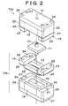
- FIG. 2 is an exploded perspective view which shows an interior structure of an electromagnetic actuator 7.
- the core assemblies 12a and 12b are arranged symmetrically from the armature 11.
- the two core assemblies 12a and 12b are identical except for their arrangement and working timing such that only the core assembly 12b is referred to hereafter.
- the core assembly 12b includes a core plate 21 with which the core 18 contacts, and a pair of core blocks 22.
- the pair of core blocks 22 contact the core plate 21 and is provided in a way such that the core 18 is located between the core blocks 22.
- the coil unit 19 having an annular shape includes a coil part 23 into which the coil 20 (e.g., shown in FIG. 1) is embedded, and a pair of spacers 24 which is formed integrally with the coil part 23 at the outer margins of and on top of the coil part 23 (e.g., as shown in FIG. 2).
- the coil part 23 is molded out of a thermoplastic resin to be integral with the coil 20.
- the spacers 24 are also molded out of thermoplastic to be integral with the coil 20.
- the coil unit 19 On a side opposite to the armature 11 (the under-side of the coil part 23 and the spacers 24, e.g., as shown in FIG. 2), the coil unit 19 has a noise absorbing material 25 attached, which is a sheet-shape and contains a foam metal such as a foam cast iron.
- a retaining groove 26 with an annular shape, which houses the coil part 23, is formed in the core 18 and the core blocks 22.
- the coil unit 19 is matingly fixed on the core 18 and the core blocks 22 by inserting the coil part 23 into the retaining groove 26.
- the spacers 24 are located above the core blocks 22 as shown in FIG. 2.
- the noise absorbing material 25 attached on the coil unit 19 is located between two groups. One group comprises the coil part 23 and the spacers 24. The other group comprises the core 18 and the core blocks 22.
- Pin holes 27, through which pins 15 penetrate, and bolt holes 28 into which bolts 16 are screwed, are formed in the spacers 24, core blocks 22, and the core plate 21.
- the pins 15 and the bolts 16 are shown in FIG. 1.
- the core assemblies 12a and 12b are fixed to meet at least the following two requirements. The first requirement is that the armature 11 is arranged between the core assemblies 12a and 12b. The second requirement is that the spacers 24 on both sides of the core assembly 12a and 12b are contacted together. This arrangement is fixed by tightening the bolts 16 screwed into the bolt holes 28 after inserting the pins 15 into the pin holes 27.
- the spacers 24 are located on both sides of the armature 11 (along the moving path of the armature shaft 10) and between the electromagnet 30a of the core assembly 12a and the electromagnet 30b of the core assembly 12b.
- the relative position of the electromagnets 30a and 30b to the neutral position of the armature 11 is determined by the spacers 24.
- a space 11a for the armature 11 to reciprocate between the core assemblies 12a and 12b is secured.
- Maximum displacement of the armature 11 is determined in proportion to the length of moving direction of the armature 11 in the space 11a.
- the spacers 24, for determining the relative positions of the electromagnets 30a and 30b to the neutral position of the armature 11, are located between the electromagnets 30a and 30b. Therefore, the spacers 24 do not deviate in the reciprocating direction of the armature 11 (e.g., in the direction of the axis of the armature shaft 10).
- the spacers 24 are formed by molding to be integral with the coils 20 as the coil unit 19. Therefore, the number of components of the electromagnetic actuator 7 are few and is not increased. Furthermore, deviation of the relative position of the electromagnets 30a and 30b from the neutral position of the armature 11 from an appropriate position can be prevented. Change in the maximum displacement of the armature 11 accompanied by the above-mentioned deviation can also be prevented.
- the spacers 24 are located on opposite sides of the armature 11 as viewed in a direction perpendicular to the moving direction of the armature 11. Because of the above-described relation of the positions among the spacers 24 and the armature 11, the spacers 24 are located between the electromagnets 30a and 30b. Both electromagnets 30a and 30b are located along the axis of the armature shaft 10. Therefore, the position of the electromagnets 30a and 30b relative to the neutral position of the armature 11 can be determined by the spacers 24 appropriately and the maximum displacement of the armature 11 can be maintained within an appropriate value with greater certainty.
- the level of contact noise caused by contacting the armature 11 with the core assemblies 12a and 12b, as the armature 11 reciprocates, can be lowered by the noise absorbing materials 25 located between the two groups of components.
- one group comprises the coil part 23 and the spacers 24.
- the other group comprises the core 18 and the core blocks 22.
- the exemplary embodiment may be modified as follows.
- each spacer 24 may be provided at each coil unit 19.
- the two coil units 19 may be installed in the electromagnetic actuator in the way that spacers 24 of coil units 19 are located on opposite sides of the armature 11 as viewed in a direction perpendicular to the moving direction of the armature 11.
- the noise absorbing material 25 is attached to the coil part 23 and the spacers 24 on the side opposite to the armature 11 (e.g., the under-side of the coil part 23 and the spacers 24 as shown in FIG. 2).
- the noise absorbing material 25 may be attached either on the coil part 23 or the spacers 24.
- the noise absorbing material 25 is optional and can be omitted to reduce the number of components.
- the electromagnetic actuator 7 may be applied to structures other than an engine valve.
- An electromagnetic actuator (7) includes a pair of core assemblies (12a, 12b) and a spacer (24).
- the armature (11) is provided between the pair of core assemblies (12a, 12b).
- the spacer (24) is formed by molding to be integral with a coil (20) provided in electromagnets (30a, 30b) of the core assemblies (12a, 12b) and is located between the electromagnets (30a, 30b). And relative positions of the pair of electromagnets (30a and 30b) to each other are determined by the spacer (24).
- a space to allow the armature to reciprocate is secured between the core assemblies (12a, 12b) by the spacer (24).
Landscapes
- Physics & Mathematics (AREA)
- Electromagnetism (AREA)
- Engineering & Computer Science (AREA)
- Power Engineering (AREA)
- Mechanical Engineering (AREA)
- General Engineering & Computer Science (AREA)
- Valve Device For Special Equipments (AREA)
- Magnetically Actuated Valves (AREA)
- Electromagnets (AREA)
Abstract
Description
Selected Figure: FIG. 2
Claims (9)
- An electromagnetic actuator including a pair of electromagnets (30a, 30b) being provided on opposite sides of the armature (11) reciprocating between the pair of electromagnets (30a, 30b) by electromagnetic attraction with a coil (20) being provided inside each the electromagnet (30a, 30b), characterized in that a spacer (24), that secures a space for the armature (11) to reciprocate, is formed by molding to be integral with the coil (20) and is located between the pair of electromagnets (30a, 30b).
- The electromagnetic actuator according to claim 1, wherein the electromagnetic actuator has at least two of the spacers (24).
- The electromagnetic actuator according to claim 2, wherein the spacers (24) are located on opposite sides of the armature (11) as viewed in a direction perpendicular to the moving direction of the armature (11).
- The electromagnetic actuator according any one of claims 1 to 3, wherein a noise absorbing material (25) is provided between a first surface defined by at least one of the spacer (24) and the coil (20) opposite to a side adjacent to the armature (34) and a second surface defined matingly opposite to the first surface.
- The electromagnetic actuator according claim 4, wherein the noise absorbing material (25) is provided on at least one of the spacer (24) and the coil (20).
- The electromagnetic actuator according to claim 4 or claim 5, wherein the noise absorbing material (25) comprises a foam metal.
- The electromagnetic actuator according to any one of claims 1 to 6, wherein a surface of the armature (11) is hardened by a surface-hardening treatment.
- The electromagnetic actuator according any one of claims 1 to 7, wherein the electromagnetic actuator is provided in an internal combustion engine to drive a valve body of an intake valve.
- The electromagnetic actuator according any one of claims 1 to 7, wherein the electromagnetic actuator is provided in an internal combustion engine to drive a valve body (4) of an exhaust valve.
Applications Claiming Priority (2)
| Application Number | Priority Date | Filing Date | Title |
|---|---|---|---|
| JP2001150651 | 2001-05-21 | ||
| JP2001150651A JP2002343631A (en) | 2001-05-21 | 2001-05-21 | Electromagnetic actuator |
Publications (2)
| Publication Number | Publication Date |
|---|---|
| EP1260997A2 true EP1260997A2 (en) | 2002-11-27 |
| EP1260997A3 EP1260997A3 (en) | 2003-01-29 |
Family
ID=18995635
Family Applications (1)
| Application Number | Title | Priority Date | Filing Date |
|---|---|---|---|
| EP02010452A Withdrawn EP1260997A3 (en) | 2001-05-21 | 2002-05-08 | Electromagnetic actuator |
Country Status (3)
| Country | Link |
|---|---|
| US (1) | US20020170512A1 (en) |
| EP (1) | EP1260997A3 (en) |
| JP (1) | JP2002343631A (en) |
Cited By (1)
| Publication number | Priority date | Publication date | Assignee | Title |
|---|---|---|---|---|
| FR2870630A1 (en) * | 2004-05-24 | 2005-11-25 | Johnson Contr Automotive Elect | ELECTROMAGNETIC ACTUATOR COMPRISING AN ELECTROAIMANT WITH A COIL FREE FROM THE CORE |
Families Citing this family (3)
| Publication number | Priority date | Publication date | Assignee | Title |
|---|---|---|---|---|
| JP2004360626A (en) * | 2003-06-06 | 2004-12-24 | Hitachi Unisia Automotive Ltd | Fuel injection valve |
| JP4840145B2 (en) * | 2006-01-17 | 2011-12-21 | 株式会社デンソー | Solenoid valve device |
| EP3256727B1 (en) * | 2015-02-11 | 2018-12-12 | Dott. Ing. Mario Cozzani S.r.l. | Flow control actuator for reciprocating compressors |
Family Cites Families (4)
| Publication number | Priority date | Publication date | Assignee | Title |
|---|---|---|---|---|
| DE29700096U1 (en) * | 1997-01-04 | 1998-04-30 | FEV Motorentechnik GmbH & Co. KG, 52078 Aachen | Electromagnetic actuator for actuating a gas exchange valve with damping means to reduce the transmission of structure-borne noise |
| US6094118A (en) * | 1997-12-09 | 2000-07-25 | Siemens Automotive Corporation | Electromagnetic actuator with stamped steel housing |
| DE19914591B4 (en) * | 1999-03-31 | 2004-04-15 | Conti Temic Microelectronic Gmbh | Process for the production of electromagnets |
| DE19924812A1 (en) * | 1999-05-29 | 2000-12-07 | Daimler Chrysler Ag | Process for the production of actuators for electromagnetic valve control |
-
2001
- 2001-05-21 JP JP2001150651A patent/JP2002343631A/en active Pending
-
2002
- 2002-04-26 US US10/132,146 patent/US20020170512A1/en not_active Abandoned
- 2002-05-08 EP EP02010452A patent/EP1260997A3/en not_active Withdrawn
Cited By (2)
| Publication number | Priority date | Publication date | Assignee | Title |
|---|---|---|---|---|
| FR2870630A1 (en) * | 2004-05-24 | 2005-11-25 | Johnson Contr Automotive Elect | ELECTROMAGNETIC ACTUATOR COMPRISING AN ELECTROAIMANT WITH A COIL FREE FROM THE CORE |
| WO2005119708A3 (en) * | 2004-05-24 | 2007-04-26 | Valeo Sys Controle Moteur Sas | Electromagnetic actuator comprising two electromagnets provided with coils which are free in relation to the cores |
Also Published As
| Publication number | Publication date |
|---|---|
| EP1260997A3 (en) | 2003-01-29 |
| JP2002343631A (en) | 2002-11-29 |
| US20020170512A1 (en) | 2002-11-21 |
Similar Documents
| Publication | Publication Date | Title |
|---|---|---|
| US7766303B2 (en) | Electromagnetic valve apparatus | |
| JP3151793B2 (en) | Solenoid operated flow control valve assembly | |
| US6049264A (en) | Electromagnetic actuator with composite core assembly | |
| JP3111062B2 (en) | Solenoid actuator assembly | |
| US6526928B2 (en) | Electromagnetic multiple actuator | |
| US5903070A (en) | Electromagnetic actuator having a slender structure | |
| EP1260997A2 (en) | Electromagnetic actuator | |
| EP0834013B1 (en) | Fuel pump | |
| US7418932B2 (en) | Electromagnetically driven valve | |
| US20040149944A1 (en) | Electromechanical valve actuator | |
| JP2005176595A (en) | Electromagnetic valve actuator system | |
| US20050076866A1 (en) | Electromechanical valve actuator | |
| CN116753088B (en) | Solenoid valve gas fuel injector | |
| US20010032603A1 (en) | Engine valve operating system for internal combustion engine | |
| US7353787B2 (en) | Electromagnetically driven valve | |
| US6787946B2 (en) | Actuator having a permanent magnet | |
| JP2000027616A (en) | Valve train for internal combustion engine | |
| US7430996B2 (en) | Electromagnetically driven valve | |
| KR102333981B1 (en) | Electromagnetically actuated gas injection valve | |
| EP1093543B1 (en) | Flexible armature for fuel injection system control valve | |
| US20070290156A1 (en) | Electromagnetically Driven Valve | |
| US7305942B2 (en) | Electromechanical valve actuator | |
| US7387094B2 (en) | Electromagnetically driven valve | |
| US7305943B2 (en) | Electromagnet assembly for electromechanical valve actuators | |
| JP4174822B2 (en) | Electromagnetically driven valve device |
Legal Events
| Date | Code | Title | Description |
|---|---|---|---|
| PUAI | Public reference made under article 153(3) epc to a published international application that has entered the european phase |
Free format text: ORIGINAL CODE: 0009012 |
|
| 17P | Request for examination filed |
Effective date: 20020508 |
|
| AK | Designated contracting states |
Kind code of ref document: A2 Designated state(s): AT BE CH CY DE DK ES FI FR GB GR IE IT LI LU MC NL PT SE TR |
|
| AX | Request for extension of the european patent |
Free format text: AL;LT;LV;MK;RO;SI |
|
| PUAL | Search report despatched |
Free format text: ORIGINAL CODE: 0009013 |
|
| RIC1 | Information provided on ipc code assigned before grant |
Free format text: 7H 01F 7/16 A, 7F 01L 9/04 B |
|
| AK | Designated contracting states |
Designated state(s): AT BE CH CY DE DK ES FI FR GB GR IE IT LI LU MC NL PT SE TR |
|
| AX | Request for extension of the european patent |
Extension state: AL LT LV MK RO SI |
|
| 17Q | First examination report despatched |
Effective date: 20030319 |
|
| AKX | Designation fees paid |
Designated state(s): DE FR GB IT |
|
| STAA | Information on the status of an ep patent application or granted ep patent |
Free format text: STATUS: THE APPLICATION IS DEEMED TO BE WITHDRAWN |
|
| 18D | Application deemed to be withdrawn |
Effective date: 20030730 |