BACKGROUND OF THE INVENTION
Field of the Invention
This invention relates to a process cartridge, an
electrophotographic apparatus and an image-forming
method.
Related Background Art
Image-forming apparatus making use of an
intermediate transfer belt are effective as full-color
or multi-color image-forming electrophotographic
apparatus in which a plurality of component-color toner
images corresponding to full-color image information or
multi-color image information are sequentially
transferred to and superimposed on a transfer medium to
output an image-formed material on which a full-color
image or multi-color image has synthetically been
reproduced.
Compared with conventional-technique full-color
electrophotographic apparatus having an image-forming
system in which toner images are transferred from a
first image-bearing member electrophotographic
photosensitive member to a second image-bearing member
transfer medium fastened or attracted onto a transfer
drum (e.g., the transfer system disclosed in Japanese
Patent Application Laid-Open No. 63-301960), the
full-color electrophotographic apparatus having an
intermediate transfer belt have such an advantage that
a great variety of second image-bearing members
(transfer mediums) can be selected without regard to
their width and length, including thin paper (40 g/m2
paper) and even thick paper (200 g/m2 paper) such as
envelopes, post cards and labels. This is because the
use of the intermediate transfer belt makes any
processing or control (e.g., the transfer medium is
held with a gripper, attracted, and made to have a
curvature) unnecessary for the transfer medium.
In addition, the intermediate transfer member made
in the shape of a belt enables effective utilization of
space to make the apparatus main body compact and
achieve cost reduction, because placement freedom in
the image-forming apparatus can be greater than a case
in which a rigid cylinder such as an intermediate
transfer drum is used.
However, the intermediate transfer belt has a
shorter lifetime than the electrophotographic-apparatus
main body, and hence, under the existing conditions, it
is indispensable to replace the belt in the middle of
the use of apparatus. At the same time, it is
necessary to install a waste-toner container in which
the toner having remained on the intermediate transfer
belt is to be collected, and to dispose of the toner
thus collected.
In addition to these, it is necessary to replace
many component parts such as an electrophotographic
photosensitive member and a developing assembly, and
the toner.
As a method of making these replacement parts into
a unit or units (process cartridge) so as to be
attached to or detached from the main body with ease,
Japanese Patent Application Laid-Open No. 8-137181
discloses a technique in which the intermediate
transfer belt and the electrophotographic
photosensitive member are made into units independent
of each other and are so placed as to be attached to or
detached from the main body with ease.
However, such a means requires replacement units
in a large number and makes user's operation
troublesome. Also, since the units are designed and
placed independently of each other, a problem may arise
such that the apparatus must be made large-sized and
may involve a high cost.
As a means for solving such a problem, a technique
is proposed in which the intermediate transfer belt and
the electrophotographic photosensitive member as
replacement parts are made into one unit (process
cartridge) so as to be simultaneously attached to or
detached from the main body and replaced. Such a
technique is disclosed in, e.g., Japanese Patent
Applications Laid-Open No. 6-110261, No. 10-177329 and
No. 11-30944.
However, differently from a case in which the
intermediate transfer belt is set at the time the
apparatus main body is installed, such a technique in
which the intermediate transfer belt and the
electrophotographic photosensitive member are set up as
one unit to provide a process cartridge which can be
attached to or detached from the main body with ease,
namely, the intermediate transfer belt and the
electrophotographic photosensitive member are
integrally set as a process cartridge, tends to cause
some problems ascribable to the intermediate transfer
belt.
One of such problems is a lowering of belt
strength which is caused by a tension applied to the
intermediate transfer belt.
Usually, in order for the intermediate transfer
belt to be surely driven without slipping, a tension
must be applied thereto, where the process cartridge in
which the intermediate transfer belt and the
electrophotographic photosensitive member are
integrally supported stands stationary as the tension
is kept applied for a long time until it is actually
put into use. As a result, the intermediate transfer
belt may cause a creep to increase in peripheral
length.
The peripheral length having increased is absorbed
to a certain extent by a tension roller having a
stroke. However, the belt has already come to have a
lower modulus of elasticity than an initial preset
value, and may cause serious color misregistration when
used actually, resulting in a lowering of image quality
level.
An intermediate transfer belt having a small
elongation may also have such a great problem that it
is cracked because of such tension and vibration at the
time of distribution in the market.
The phenomenon of creep is known to be more
accelerated in a high-temperature environment, and the
process cartridge in which the intermediate transfer
belt and the electrophotographic photosensitive member
are integrally supported must be designed also taking
account of such a high-temperature environment the
process cartridge may have during its distribution.
In particular, with the progress of technique for
image-forming apparatus in recent years, it has become
possible for digital-development type printers and
copying machines to develop minute and accurate latent
images with a resolution of 600 dpi or more as exposure
spots have been made smaller in size and more highly
dense, and to obtain images with a high quality on
account of, e.g., precise control of electric fields.
As a result, a change in modulus of elasticity and
surface roughness of the intermediate transfer belt,
which have not come into question in the past, may
greatly affect image quality, and it is an important
subject to solve this problem.
In the above conventional techniques, however, any
measure is not taken against difficulties the process
cartridge in which the intermediate transfer belt and
the electrophotographic photosensitive member are
integrally supported may have when, e.g., left for a
long time during transportation and storage, and it can
not be said that any process cartridges have been
designed taking such distribution channels into
account. Hence, in the conventional process cartridge
in which the intermediate transfer belt and the
electrophotographic photosensitive member are
integrally supported, there are problems such that a
high management cost may result because of, e.g.,
strict safekeeping and restriction on a period of
service, and that complaints from users may increase.
In addition, it is also an important subject to
reduce running cost, and much more cost reduction must
be achieved on the process cartridge in which the
intermediate transfer belt and the electrophotographic
photosensitive member are integrally supported and
which come to be a replacement part. Also, in order to
make handling easy, the miniaturization and the
disposal of waste toner should fully be taken into
consideration.
Thus, any process cartridge having perfectly
solved the technical problems peculiar to the process
cartridge in which the intermediate transfer belt and
the electrophotographic photosensitive member are
integrally supported and any electrophotographic
photosensitive member having such a process cartridge
have not been made available.
SUMMARY OF THE INVENTION
An object of the present invention is to provide a
process cartridge which is easy of maintenance, enables
miniaturization and cost reduction of apparatus, and
affords good images even when having transported or
left over a long period of time; an electrophotographic
apparatus having such a process cartridge; an
image-forming method making use of the
electrophotographic apparatus; and an intermediate
transfer belt for the process cartridge.
The present inventors have made extensive studies
on the achievement of simple maintenance,
miniaturization and cost reduction of process
cartridges and improvement in image quality. As a
result, they have discovered that the intended object
can be achieved by employing a process cartridge in
which the intermediate transfer belt and the
electrophotographic photosensitive member are
integrally supported, further in combination with some
measures.
More specifically, the present invention is a
process cartridge which is detachably mountable to the
main body of an electrophotographic apparatus; the
process cartridge integrally comprising:
The present invention is also an
electrophotographic apparatus comprising:
The present invention is still also an
image-forming method comprising the steps of:
BRIEF DESCRIPTION OF THE DRAWINGS
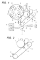
Fig. 1 is a schematic sectional view showing an
example of an electrophotographic apparatus making use
of the intermediate transfer belt/electrophotographic
photosensitive member integral cartridge of the present
invention.
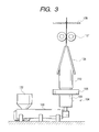
Fig. 2 is a schematic sectional view showing the
construction of the process cartridge of the present
invention.
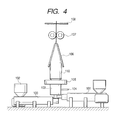
Fig. 3 is a view showing an example of a
production apparatus for producing an intermediate
transfer belt (single layer).
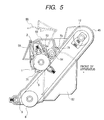
Fig. 4 is a view showing an example of a
production apparatus for producing an intermediate
transfer belt (double layer).
Fig. 5 is a schematic view showing the
construction of a process cartridge comprising an
electrophotographic photosensitive member unit and an
intermediate transfer belt unit which are joined to
each other, used in Examples and Comparative Examples.
Fig. 6 is a schematic view showing the
construction of the intermediate transfer belt unit.
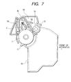
Fig. 7 is a schematic view showing the
construction of the electrophotographic photosensitive
member unit.
Fig. 8 is a view showing how the process cartridge
of the present invention is attached to or detached
from the electrophotographic apparatus.
DETAILED DESCRIPTION OF THE INVENTION
Embodiments of the present invention are described
below in detail.
The process cartridge of the present invention is
a process cartridge in which an intermediate transfer
belt and an electrophotographic photosensitive member
are integrally supported (herein also "intermediate
transfer belt/electrophotographic photosensitive member
integral cartridge").
In the present invention, for the purpose of
miniaturization and cost reduction of process
cartridges, a cleaning mechanism for the intermediate
transfer belt employs the so-called
cleaning-at-primary-transfer method (also called "bias
cleaning method"), in which the transfer residual toner
is charged to a reverse polarity and is returned from
the intermediate transfer belt to the
electrophotographic photosensitive member
simultaneously with primary transfer.
Stated specifically, it is a method in which
electric charges with a polarity reverse to that at the
time of primary transfer are imparted to the toner
having remained on the intermediate transfer belt at
the time of secondary transfer, by applying a voltage
to a charge-providing member disposed separably on the
intermediate transfer belt, and the toner is returned
to the electrophotographic photosensitive member by the
aid of a primary-transfer electric field at the
subsequent primary-transfer zone.
The toner having been returned from the surface of
the intermediate transfer belt to the
electrophotographic photosensitive member is removed by
a cleaning means for the electrophotographic
photosensitive member, such as a cleaning blade.
This method is greatly effective to make the
cartridge compact and low-cost, compared with a method
in which cleaning blades or the like are provided for
both the electrophotographic photosensitive member and
the intermediate transfer belt and a feed mechanism for
waste toner and a container therefor are installed.
In addition, in the present invention, the process
cartridge is designed for strength, considering that a
tension is applied to the intermediate transfer belt
for a long time and also the environment may change to
cause the phenomenon of creep. Hence, even an
intermediate transfer belt cartridge which has been
manufactured for a long time can form good images
without causing any problems.
Stated specifically, the intermediate transfer
belt has a modulus of elasticity of 500 MPa to 4,000
MPa at elongation from 0.5% to 0.6% in the peripheral
direction. As long as it has a modulus of elasticity
of 500 MPa or more, color misregistration may be
reduced when images are formed. On the other hand, if
it has a modulus of elasticity of more than 4,000 MPa,
the intermediate transfer belt may have so high a
rigidity as to hinder its smooth rotation.
The intermediate transfer belt also has a breaking
extension of from 5% to 850% in the peripheral
direction. If it has a breaking extension of less than
5%, it may be brittle as a belt to cause a break upon a
little elongation. Hence, in the case of the process
cartridge expected to be stored for a long term as a
tension is kept applied until it is put to use, there
may occur such a problem that the intermediate transfer
belt has a short lifetime. On the other hand, if it
has a breaking extension of more than 850%, the
intermediate transfer belt may elongate so greatly that
it may undergo expansion and contraction at the time of
its rotation to cause color misregistration.
As to the intermediate transfer belt, its surface
roughness must also be taken into account. It may have
a surface roughness Ra of 1 µm or less. If it has a
surface roughness Ra of more than 1 µm, the transfer
performance may be affected to cause coarse halftone
images or a lowering of fine-line reproducibility.
Also, the electric charges imparted to the
secondary-transfer residual toner may become
non-uniform, or intermediate transfer belt faulty
cleaning may occur in which the secondary-transfer
residual toners are not sufficiently returned to the
electrophotographic photosensitive member to cause such
a trouble that previously printed images remain on
subsequently printed images at the time of continuous
printing.
In particular, these problems concerning images
may remarkably occur in electrophotographic apparatus
having a digital exposure means which forms
electrostatic latent images on the surface of the
electrophotographic photosensitive member by a digital
method with a resolution of 600 dpi or more.
Meanwhile, in order to make the intermediate
transfer belt/electrophotographic photosensitive member
integral cartridge have a smaller size and lower price,
it is also important to select the shape of the
electrophotographic photosensitive member to be
incorporated in the cartridge. Accordingly, the
electrophotographic photosensitive member may
preferably be a small-diameter, drum-shaped
electrophotographic photosensitive member
(photosensitive drum) formed of a rigid body having a
diameter of 60 mm or less, which may require a simple
drive mechanism and can be made compact with ease.
For the same purpose as the above, the
intermediate transfer belt may be one which is placed
over and around two rollers consisting of, e.g., a
drive roller and a tension roller. This is more
preferable because the number of component parts can be
cut down and the cartridge can be made more compact.
The tension roller, which applies tension to the
intermediate transfer belt, must slide by at least 1 mm
with respect to the direction of elongation of the
intermediate transfer belt, in order to deal with any
elongation of the intermediate transfer belt. In order
for the intermediate transfer belt to be surely driven
without slipping, the intermediate transfer belt may
preferably be fitted over and around the two rollers at
a force of 5 N or more.
As to the intermediate transfer belt, its
resistivity must also be regulated. The intermediate
transfer belt may have a volume resistivity of from 1 ×
106 Ω·cm to 8 × 10¹³ Ω·cm, within the range of which
good images are obtainable. If it has a volume
resistivity lower than 1 × 10⁶ Ω·cm, no sufficient
transfer electric field may be provided, tending to
cause blank areas in images or coarse images. If on
the other hand it has a volume resistivity higher than
8 × 10¹³ Ω·cm, the transfer voltage must also be made
higher, requiring a power source to be in a large size
or resulting in a higher cost.
The intermediate transfer belt may also have a
wall thickness in the range of from 40 µm to 300 µm.
If it has a thickness smaller than 40 µm, it may lack
in forming stability, tends to cause uneven thickness
and may have insufficient durability and strength,
where the belt may break or crack. If on the other
hand it has a thickness larger than 300 µm, materials
must be used in a large quantity, resulting in a high
cost. Moreover, the intermediate transfer belt may
have a large difference in peripheral speed between the
inner surface and the outer surface of the belt at its
part where it is put over the shaft of a printer or the
like, tending to cause problems of, e.g., spots around
line images due to the expansion and contraction of the
outer surface. The belt may have a low flex durability
or have so high a rigidity as to make the drive torque
greater, requiring the main body to be in a large size
or resulting in a higher cost. Such a problem also
tends to occur.
In the present invention, the intermediate
transfer belt and the electrophotographic
photosensitive member are integrally supported to make
up a cartridge, and it is sufficient for them to be
combined when used by users. Taking into account
readiness of handling in the course of manufacture and
readiness of disassembly after recovery, it is
preferred that they are so designed as to be divided
into some smaller units, e.g., an intermediate transfer
belt unit and an elecrophotographic photosensitive
member unit.
There are no particular limitations on means by
which the modulus of elasticity specified in the
present invention is attained. Any resins used as a
raw material for the intermediate transfer belt and
various additives thereto may be selected so that the
breaking extension and the modulus of elasticity at
elongation from 0.5% to 06% may be regulated within the
ranges of numerical values specified in the present
invention.
For example, a filler such as inorganic particles
may be mixed, whereby a reinforcing effect can be
obtained and the modulus of elasticity can be enhanced.
Here, the material and amount of the filler and a
resin(s) may be so selected as to regulate the modulus
of elasticity within the range specified in the present
invention. Also, the filler may have a fibrous or
plate-like shape, where a high reinforcing effect can
be obtained even if the belt has elongated.
The intermediate transfer belt may also be
produced by blending two or more kinds of resins having
different breaking extensions and being not compatible
with each other. Such a method is also effective.
Where the intermediate transfer belt is produced using
such materials, the respective resins are finely
separated and present in the belt in a laminar or
fibrous form. With the intermediate transfer belt thus
produced, its strength is, at the initial stage,
undertaken by the resin having a small breaking
extension. However, when creep is brought about over
time and the resin having a small breaking extension
exceeds its yield point, the resin having a large
breaking extension instead undertakes the strength.
Thus, the modulus of elasticity can be prevented from
abruptly lowering.
There are no particular limitations on means by
which the surface roughness of the intermediate
transfer belt is regulated.
For example, a method is available in which
regulation is effected in such a way that, when
extrusion is carried out, resin materials are selected
for melt properties and temperature conditions and
cooling conditions at the time of extrusion are
adjusted so that more smooth surface can be attained
when an extruded product, melt-extruded into a film, is
solidified from a molten state.
Other available methods include a method in which
a product extruded into a belt is heated applying a
smooth form (for shaping) so as to have the same
surface state as the form, and a method in which the
surface of a belt is polished.
The process for producing the intermediate
transfer belt may preferably be a production process
which can produce a seamless belt and has a high
production efficiency to enable cost saving. As a
means therefor, a method is available in which an
extrusion material is continuously melt extruded from a
circular die and thereafter the product thus extruded
is cut in a necessary length to produce a belt. Stated
specifically, an intermediate transfer belt production
process (called blown-film extrusion, or inflation) is
preferred which has the steps of:
The tubular film having been formed through the
tubular-film forming step may also preferably have a
wall thickness which is 1/3 or less, and more
preferably 1/5 or less, with respect to the slit width
of the circular die. This value represents the
stretched state of the material. If the tubular film
has a wall thickness which is larger than 1/3 with
respect to the slit width of the circular die, the
material may insufficiently stretch and may cause
troubles such as low strength, uneven resistance and
uneven thickness.
The tubular film having been formed through the
tubular-film forming step may also preferably have a
diameter (outer diameter of the tubular film) which is
from 50% to 400%, and more preferably from 101% to
300%, with respect to the diameter of the circular die
(outer diameter of the slit of the circular die). If
it is more than 400%, the film has been stretched in
excess in the peripheral direction, and if it is less
than 50%, the film has been stretched almost in the
flow direction (extrusion direction), resulting in low
extrusion stability or making it difficult to ensure
the thickness and strength necessary for obtaining the
effect of the present invention.
An example of the process for producing the
intermediate transfer belt used for the process
cartridge of the present invention is described below.
It should be noted that the present invention is by no
means limited to this example.
Fig. 3 shows an example of an appratus for
producing the intermediate transfer belt used in the
process cartridge of the present invention. This
production apparatus consists chiefly of an extruder
100, an extruder die 103, and a gas blowing unit having
a gas inlet passage 104.
First, an extrusion resin, a conducting agent and
additives are premixed under the desired formulation
and thereafter kneaded and dispersed to prepare an
extrusion material, which is then put into a hopper 102
installed in the extruder 100.
The extruder 100 has a preset temperature,
extruder screw construction and so forth which have
been so selected that the extrusion material may have a
melt viscosity necessary for the extrusion into a belt
in the subsequent step and the materials can be
dispersed uniformly one another. The extrusion
material is melt-kneaded in the extruder 100 into a
melt, which then enters a circular die 103.
The circular die 103 is provided with a gas inlet
passage 104. Through the gas inlet passage 104, a gas
is blown into the circular die 103, whereupon the melt
having passed through the circular die 103 in a tubular
form inflates while scaling up in the diametrical
direction.
The gas to be blown here may be air, and besides,
may be selected from nitrogen, carbon dioxide and
argon.
The extruded product having thus inflated is drawn
upward while being cooled by an outside-cooling ring
105, and formed into a tubular film 110. Usually, in
such a blown-film extrusion apparatus, a method is
employed in which the tubular film 110 is pressed
forcibly from the right and the left by means of
stabilizing plates 106 to fold it into a sheet, and
then drawn off at a constant speed while being so
sandwiched with pinch rollers 107 that the air in the
interior does not escape. Then, the film 110 thus
drawn off is cut with a cutter 108 to obtain a tubular
film with the desired size.
Next, this tubular film is worked using a form
(for shaping) in order to regulate its surface
smoothness and size and to remove any folds made in the
film at the time of draw-off.
Stated specifically, a method is usable which
makes use of a pair of cylindrical forms which are made
of materials which are different from each other in
coefficient of thermal expansion and diameter.
In this method, a small-diameter cylindrical form
(inner form) is so made as to have a coefficient of
thermal expansion larger than the coefficient of
thermal expansion of a large-diameter cylindrical form
(inner form). A tubular film obtained by extrusion is
placed over this inner form. Thereafter, the inner
form with film is inserted into the outer form so that
the tubular film is held between the inner form and the
outer form. A gap between the inner form and the outer
form may be determined by calculation on the bases of
heating temperature, difference in coefficient of
thermal expansion between the inner form and the outer
form, and pressure required.
The form set having in this order the inner form,
the tubular film and the outer form is heated to the
vicinity of the softening point temperature of resin.
As a result of the heating, the inner form, having a
larger coefficient of thermal expansion, expands more
than the outer form and a uniform pressure is applied
to the whole tubular film (resin film). Here, the
surface of the resin film having reached the vicinity
of its softening point is pressed against the inner
surface of the outer form having been worked smoothly,
so that the smoothness of the surface of the resin film
is improved. Thereafter, these are cooled and the film
is removed from the forms, thus smooth surface
characteristics can be attained.
Thereafter, this tubular film is optionally fitted
with a reinforcing member, a guide member and a
position detection member, and is precisely cut to
produce the intermediate transfer belt.
The foregoing description relates to a
single-layer belt. In the case of a belt of
double-layer construction, an extruder 101 is
additionally provided as shown in Fig. 4.
Simultaneously with the kneaded melt held in the
extruder 100, a kneaded melt in the extruder 101 is
sent to a double-layer circular die 103, and the two
layers are scale-up inflated simultaneously, thus a
double-layer belt can be obtained.
In the case of triple- or more layer construction,
the extruder may of course be provided in the number
corresponding to the number of layers.
Thus, the above intermediate transfer belt
production process makes it possible to extrude not
only intermediate transfer belts of single-layer
construction but also those of multi-layer construction
in a good dimensional precision through a series of
steps and in a short time. That the etrusion can be
made in a short time means that mass production and
low-cost production can be made.
The resin which is a chief material among
extrusion materials used in the intermediate transfer
belt for the process cartridge of the present invention
may be any of those which can satisfy the intermediate
transfer belt characteristics according to the present
invention, without any particular limitation. It is
preferable to use at least one of, e.g., olefin resins
such as polyethylene and polypropylene, polystyrene
resins, acrylic resins, polyester resins,
polycarbonate, sulfur-containing resins such as
polysulfone, polyether sulfone and polyphenylene
sulfide, fluorine-containing resins such as
polyvinylidene fluoride and a
polyethylene-tetrafluoroethylene copolymer,
polyurethane resins, silicone resins, ketone resins,
polyvinylidene chloride, thermoplastic polyimide
resins, polyamide resins, modified polyphenylene oxide
resins, and various modified resins or copolymers of
any of these. However, examples are by no means
limited to the above materials.
Then, there are no particular limitations on the
additives which may be mixed in order to regulate the
electrical resistance value of the intermediate
transfer belt for the process cartridge of the present
invention. As a conductive filler for regulating the
resistance, it includes carbon black and various
conductive metal oxides. As a non-filler type
resistance regulator, it includes low-molecular weight
ion conducting materials such as various metal salts
and glycols, antistatic resins containing an ether
linkage or a hydroxyl group in the molecule, and
organic polymeric compounds showing
electroconductivity.
What is required here is the dispersion state of
the components of the intermediate transfer belt, such
as the various additives and the resin. If
agglomeration of particles or extreme separation of
some components occurs, it is difficult to obtain the
effect of the present invention. It is important to
select materials and dispersion means.
Then, an example of an electrophotographic
apparatus making use of the intermediate transfer
belt/electrophotographic photosensitive member integral
cartridge of the present invention is shown in Fig. 1.
The apparatus shown in Fig. 1 is a color
electrophotographic apparatus such as a color copying
machine or a color laser beam printer.
Reference numeral 1 denotes a rotating-drum type
electrophotographic photosensitive member
(photosensitive drum) serving as a first image-bearing
member, which is rotatively driven at a prescribed
peripheral speed (process speed) in the clockwise
direction shown by an arrow.
The electrophotographic photosensitive member 1
is, in the course of its rotation, uniformly
electrostatically charged to prescribed polarity and
potential by means of a primary-charging means
(charging roller) 2. Reference numeral 32 denotes a
power source of the primary-charging means 2. Here, a
voltage formed by superimposing an AC voltage on a DC
voltage is applied. Alternatively, only an AC voltage
may be applied.
Then, the electrophotographic photosensitive
member is exposed to light 3 by a exposure means (not
shown; e.g., a color-original image
color-separating/image-forming optical system, or a
scanning exposure system comprising a laser scanner
that outputs laser beams modulated in accordance with
time-sequential electrical digital pixel signals of
image information). Thus, an electrostatic latent
image is formed which corresponds to a first color
component image (e.g., a yellow color component image)
of the intended color image.
Next, the electrostatic latent image is developed
with a first-color yellow toner Y by means of a first
developing means (yellow color developing assembly 41).
At this stage, second to fourth developing means
(magenta color developing assembly 42, cyan color
developing assembly 43 and black color developing
assembly 44) each stand unoperated and do not act on
the electrophotographic photosensitive member 1, and
hence the first-color yellow toner image is not
affected by the second to fourth developing assemblies.
An intermediate transfer belt 5 is rotatively
driven in the clockwise direction at the same
peripheral speed as that of the electrophotographic
photosensitive member 1.
While the first-color yellow toner image formed
and held on the electrophotographic photosensitive
member 1 passes through a nip formed between the
electrophotographic photosensitive member 1 and the
intermediate transfer belt 5, it is successively
primarily transferred to the periphery of the
intermediate transfer belt 5 by the aid of an electric
field formed by a primary-transfer bias applied to the
intermediate transfer belt 5 through a roller-shaped
primary-transfer means (primary-transfer roller) 6.
The electrophotographic photosensitive member 1
surface from which the first-color yellow toner image
has been transferred is cleaned by a cleaning means 13.
Subsequently, the second-color magenta toner
image, the third-color cyan toner image and the
fourth-color black toner image are sequentially
similarly transferred and superimposed onto the
intermediate transfer belt 5. Thus, the intended
synthesized color toner image is formed.
Reference numeral 7 denotes a secondary-transfer
means (secondary-transfer roller), which is provided in
such a way that it is axially supported in parallel to
a drive roller 8 and stands separable from the bottom
surface of the intermediate transfer belt 5.
The primary-transfer bias for sequentially
superimposition-transferring the first- to fourth-color
toner images from the electrophotographic
photosensitive member 1 to the intermediate transfer
belt 5 is applied from a bias source 30 in a polarity
(+) reverse to that of each toner. The voltage thus
applied is, e.g., in the range of from +100 V to +2 kV.
In the step of primary transfer of the first- to
third-color toner images from the electrophotographic
photosensitive member 1 to the intermediate transfer
belt 5, the secondary-transfer means 7 may also be set
separable from the intermediate transfer belt 5.
The synthesized color toner images transferred
onto the intermediate transfer belt 5 are transferred
to a second image-bearing member, transfer medium P, in
the following way: The secondary-transfer means 7 is
brought into contact with the intermediate transfer
belt 5 and simultaneously the transfer medium P is fed
at a prescribed timing from a paper feed roller 11
through a transfer medium guide 10 until it reaches a
contact zone formed between the intermediate transfer
belt 5 and the secondary-transfer means 7, where a
secondary-transfer bias is applied to the
secondary-transfer means 7 from a bias power source 31.
By the aid of this secondary-transfer bias, the
synthesized color toner images are secondarily
transferred from the intermediate transfer belt 5 onto
the second image-bearing member, transfer medium P.
The transfer medium P to which the toner images have
been transferred is guided into a fixing means 15 and
heat-fixed.
After the toner images have been transferred to
the transfer medium P, a charge-providing means 9
placed in a touchable and separable state is brought
into contact with the intermediate transfer belt 5, and
a bias with a polarity reverse to that of the
electrophotographic photosensitive member 1 is applied,
whereupon electric charges with a polarity reverse to
that at the time of primary transfer are imparted to
toners not transferred to the transfer medium P and
remaining on the intermediate transfer belt 5 (i.e.,
transfer residual toners). Reference numeral 33
denotes a bias power source. Here, a voltage formed by
superimposing an AC voltage on a DC voltage is applied.
The transfer residual toners charged to a polarity
reverse to that at the time of primary transfer are
electrostatically transferred to the
electrophotographic photosensitive member 1 at the zone
coming into contact with the electrophotographic
photosensitive member 1 and the vicinity thereof.
Thus, the intermediate transfer belt 5 is cleaned.
This step can be carried out simultaneously with the
primary transfer, and hence does not cause any lowering
of throughput.
Subsequently, the intermediate transfer
belt/electrophotographic photosensitive member integral
cartridge of the present invention is described.
The process cartridge of the present invention is,
as shown in Fig. 2, so constructed that at least an
electrophotographic photosensitive member 1, an
intermediate transfer belt 5, a primary-transfer means
6 and a charge-providing means 9 are integrally
supported so that it is detachably mountable to the
main body of the electrophotographic apparatus.
The process cartridge may also be so constructed
that at least one means among means the
electrophotographic apparatus has, such as an
electrophotographic-photosensitive-member cleaning
means, a primary-charging means and a waste-toner
container, can further be incorporated in the
intermediate transfer belt/electrophotographic
photosensitive member integral cartridge, or that the
electrophotographic apparatus can be provided with such
means as the electrophotographic-photosensitive-member
cleaning means, the primary-charging means and the
waste-toner container when such a process cartridge is
mounted on the electrophotographic apparatus.
The cleaning mechanism for the intermediate
transfer belt in the present invention is, as described
previously, necessary for the transfer residual toners
to be charged to a polarity reverse to that at the time
of primary transfer and thereby returned to the
electrophotographic photosensitive member at the
primary-transfer zone. In the cartridge shown in Fig.
2, a charge-providing means (intermediate-transfer-belt
cleaning roller) 9 comprised of a medium-resistance
elastic body is provided for the cleaning mechanism.
As for the cleaning of the electrophotographic
photosensitive member, it may preferably be blade
cleaning making use of an elastic blade. In the
process cartridge shown in Fig. 2, a waste-toner
container (not shown) is also integrally provided so
that the transfer residual toners on both the
intermediate transfer belt and the electrophotographic
photosensitive member may simultaneously be discarded
when the cartridge A is replaced. Thus, it contributes
to an improvement in maintenance performance.
The intermediate transfer belt is also placed over
and around two rollers, a drive roller 8 and a tension
roller 12, so that the number of component parts can be
made small and the cartridge can be made compact.
Here, the roller 8 is a drive roller and at the same
time an opposing roller of the charge-providing means
(intermediate-transfer-belt cleaning roller).
The tension roller 12, which rotates following the
intermediate transfer belt, has a sliding mechanism,
and is brought into pressure contact with the inside of
the belt in the direction of an arrow by the action of
a compression spring to impart a tension to the
intermediate transfer belt. It may be slidable in a
slide width of from 1 mm to 5 mm, and may apply a
spring pressure of from 5 N to 200 N in total.
The electrophotographic photosensitive member 1
and the drive roller 8 may also have a coupling (not
shown) so that the rotational drive force may be
transmitted from the main body.
Methods of measuring various physical properties
concerning the present invention are shown below.
- Measurement of modulus of elasticity and
breaking extension:
A measuring sample is prepared in a size of 20 mm
wide and 100 mm long, which is cut from the
intermediate transfer belt in the peripheral direction.
Its thickness is measured and thereafter the sample is
set on a tensile tester (TENSILON RTC-1250A,
manufactured by Orientec Co.). The thickness is
measured as an average at five spots. A tensile test
is made at a measurement distance of 50 mm and a
tensile speed of 5 mm/min, and elongation and stress
are recoded in a recorder, where stress at elongation
of 0.5% and 0.6% each is read. Modulus in tension is
calculated according to the following equation.
This measurement is made five times, and the value
of an average therefrom is the modulus of elasticity
referred to in the present invention.
Modulus of elasticity (MPa) =
(f2 - f1)/(20 × t) × 1,000.
In the equation, f1 represents stress at 0.5%
elongation (N); f2, stress at 0.6% elongation (N); and
t, thickness (mm) of the sample.
To measure the breaking extension, a test piece
having the same form is pulled by using the same tester
as in the above measurement of modulus of elasticity,
except that the tensile speed is changed to 50 mm/min.
Displacement L (mm) from the start of measurement at
the breaking point is recorded, and is calculated
according to the following equation.
This measurement is made five times, and the value
of an average therefrom is the breaking extension
referred to in the present invention.
Breaking extension (%) = L/50 × 100.
- Measurement of surface roughness:
This measurement is made according to JIS B0601.
- Measurement of volume resistivity:
As to measuring instruments, an ultra-high
resistance meter R8340A (manufactured by Advantest Co.)
is used as a resistance meter, and Sample Box TR42 for
ultra-high resistance measurement (manufactured by
Advantest Co.) as a sample box. The main electrode is
25 mm in diameter, and the guard-ring electrode is 41
mm in inner diameter and 49 mm in outer diameter.
A sample is prepared in the following way.
First, the intermediate transfer belt is cut in a
circular form of 56 mm in diameter by means of a
punching machine or a sharp knife. The circular cut
piece obtained is fitted, on its one side, with an
electrode over the whole surface by forming a Pt-Pd
deposited film and, on the other side, fitted with a
main electrode of 25 mm in diameter and a guard
electrode of 38 mm in inner diameter and 50 mm in outer
diameter by forming Pt-Pd deposited films. The Pt-Pd
deposited films are formed by carrying out vacuum
deposition for 2 minutes using Mild Sputter E1030
(manufactured by Hitachi Ltd.). The one on which the
vacuum deposition has been completed is used as a
measuring sample.
Measurement is conducted in a measurement
atmosphere of 23°C/55%RH. The measuring sample is
previously left standing in the like atmosphere for 12
hours or longer. Measurement is made under a mode of
discharge for 10 seconds, charge for 30 seconds and
measurement for 30 seconds and at an applied voltage of
1,000 V.
- Measurement of thickness:
Thickness unevenness of the intermediate transfer
belt of the present invention is measured with a dial
gauge measurable by 1 µm as minimum value, over the
whole periphery of the belt at points 50 mm apart from
both ends and, in respect of the middle, at four points
at equal intervals in the peripheral direction.
Measurements at 12 points in total for each
intermediate transfer belt are averaged.
The present invention is described below in
greater detail by giving specific Examples. In the
following Examples, "part(s)" means "part(s) by
weight".
In the first place, a process cartridge used in
Examples and Comparative Examples is described.
Fig. 5 schematically illustrates the construction
of a process cartridge comprising an
electrophotographic photosensitive member unit having
an electrophotographic photosensitive member and an
intermediate transfer belt unit having an intermediate
transfer belt which are joined together.
Figs. 6 and 7 schematically illustrate the
construction of the intermediate transfer belt unit and
the electrophotographic photosensitive member unit,
respectively.
Frame construction of the process cartridge is
roughly divided into two parts: an electrophotographic
photosensitive member frame 59 constructed integrally
with a waste-toner container 52, shown in Figs. 5 and
7, and an intermediate transfer belt frame 45 shown in
Figs. 5 and 6. The former comprises an
electrophotographic photosensitive member unit
constituted of an electrophotographic photosensitive
member 1, a charging roller 2, a cleaning blade 53, a
screw 54 and a drum shutter 55 as chief component
parts. The latter comprises an intermediate transfer
belt unit 51 having i) an intermediate transfer belt 5
which is put over and around a drive roller 8 and a
follower roller (tension roller) 12, ii) a
primary-transfer roller 58 provided on the inside of
the intermediate transfer belt at its part facing the
electrophotographic photosensitive member 1 and iii) a
charge-providing means (intermediate-transfer-belt
cleaning roller) 9 provided at the drive roller 8.
These two units are joined in such a way that
projections 71 provided at both ends of the
electrophotographic photosensitive member frame 59 are
respectively inserted to registration holes 72 provided
in the intermediate transfer belt frame 45 and that a
hook 73 at a snap-fitting hooking part provided at the
middle in the width direction of the
electrophotographic photosensitive member frame 59 is
fitted into a lock hole 74 of the intermediate transfer
belt frame 45.
Here, the registration holes 72 and the lock hole
74 provided in the intermediate transfer belt frame 45
are made a little larger by a certain extent than the
projections 71 and hook 73 provided on the
electrophotographic photosensitive member frame 59, and
the electrophotographic photosensitive member unit 50
and the intermediate transfer belt unit 51 are so
constructed that relative positional movement to a
certain extent is allowable between them.
The registration holes 72 are each provided with a
taper 72a so that the unit can be attached or detached
with ease.
In the process cartridge shown in Fig. 5, the hook
73 of the electrophotographic photosensitive member
unit 50 may be pushed to be unhooked from the lock hole
74 of the intermediate transfer belt unit 51, and the
electrophotographic photosensitive member unit 50 may
be turned around. Thus, the process cartridge can be
divided into the electrophotographic photosensitive
member unit and the intermediate transfer belt unit as
shown in Figs. 6 and 7.
When joined, contrary to the foregoing, the
projections 71 of the electrophotographic
photosensitive member unit 50 can be inserted into the
registration holes 72 of the intermediate transfer belt
unit 51, and the electrophotographic photosensitive
member unit 50 can be turned around in the direction
opposite to that at the time of detachment to push the
hook 73 into the lock hole 74, thereby joining the two
units.
Fig. 8 illustrates how the process cartridge of
the present invention is attached to or detached from
the electrophotographic apparatus.
Only a top cover 60 of the electrophotographic
apparatus main body can be opened to attach or detach
the process cartridge simply as in conventional
black-and-white laser beam printers. Thus, maintenance
operation such as the handling of paper jamming and
replacement of the process cartridge can be performed
with ease.
Example 1
| Production of intermediate transfer belt: |
| PVDF (polyvinylidene fluoride resin) |
100 parts |
| Polyether-containing antistatic resin |
14 parts |
In the above formulation, the antistatic resin was
so selected as to have a larger elongation than the
PVDF and not to be completely compatible with the PVDF.
These materials were melt-kneaded at 210°C by means of
a twin-screw extruder to be mixed with each other, and
the mixture obtained was extruded in the shape of a
strand of about 2 mm in diameter, followed by cutting
into pellets. This is used as an extrusion material.
Next, in the extrusion apparatus shown in Fig. 3,
the extruder die 103 was set as a single-layer circular
die, and one having a die slit outer diameter of 100 mm
was used. The slit of the circular die was 0.8 mm in
width.
The above extrusion material, having been
sufficiently dried by heating, was put into the hopper
102 of this extrusion apparatus, and heated and melted.
The molten product was extruded at 210°C from the
circular die 103. The outside-cooling ring 105 was
provided around the circular die 103, and air was blown
from the circumference to the film extruded in a
tubular form to effect cooling.
Air is also blown to the interior of the extruded
tubular film through the gas inlet passage 104 to cause
the film to inflate while scaling up to a diameter of
140 mm. Thereafter, the film was continuously drawn
off at a constant speed by means of the draw-off unit.
Here, the air was stopped being fed at the time the
diameter became the desired value.
Subsequently to the draw-off through the pinch
rollers, the tubular film was cut with the cutter 108.
The film was cut in a length of 310 mm after its
thickness became stable to form six tubular films.
For these tubular films, their size and surface
smoothness were regulated and folds were removed, using
the pair of cylindrical forms made of metals which are
different from each other in coefficient of thermal
expansion.
The tubular film were placed over the inner form,
having a higher coefficient of thermal expansion, and
this inner form with the film was inserted into the
outer form having been worked to have a smooth inner
surface, followed by heating at 170°C for 20 minutes.
After cooling, the tubular films were removed from
these cylindrical forms, and their ends were cut away,
thus six intermediate transfer belts of 140 mm in outer
diameter were produced. One of these was fitted with a
meandering preventive member so as to be used for image
examination.
Measurement of physical properties:
Five belts among these intermediate transfer belts
were left standing for 3 days in an environment of 23°C
and 55%RH, and their physical properties were measured.
First, a sample for measuring the modulus of
elasticity was one by one cut from each intermediate
transfer belt, and the modulus of elasticity was
measured by the measuring method described previously,
where the values obtained from the five belts were
averaged. As a result, the modulus of elasticity at
elongation from 0.5% to 0.6% of this intermediate
transfer belt was found to be 815 MPa.
Samples were prepared in the same way to measure
other properties to find that this belt had a breaking
extension of 20%, a surface roughness Ra of 0.03 µm, a
thickness of 102 µm and a volume resistivity of 7.8 ×
1010 Ω·cm.
Image evaluation:
The remaining one belt, not used for the
measurement of physical properties, among the six
intermediate transfer belts produced as described above
was incorporated in the intermediate transfer
belt/electrophotographic photosensitive member integral
cartridge constructed as described above. Here, the
spring pressure of the tension roller was 20 N in total
for the right and the left in an extent of slide of 2.5
mm. The tension roller and the drive roller were each
in a diameter of 28 mm. As the electrophotographic
photosensitive member, a photosensitive drum comprising
an aluminum cylinder of 47 mm in diameter and a
photosensitive layer formed thereon was used.
Subsequently, for an acceleration test, this
process cartridge was left standing in a
high-temperature environment of 40°C for 14 days.
Thereafter, this cartridge was allowed to stand still
in an environment of 23°C and 55%RH for 12 hours, and
then set in the electrophotographic apparatus
constructed as shown in Fig. 1, to test full-color
image reproduction on 80 g/m2 paper in the same
environment.
The exposure means used here was a digital
exposure means by which electrostatic latent images
were formed on the surface of the electrophotographic
photosensitive member by a digital (laser) system with
a resolution of 600 dpi.
Images obtained were visually evaluated, where
good full-color images free of any problems such as
color misregistration, uneven density and blank areas
caused by poor transfer were obtained.
Subsequently, a continuous 5,000-sheet printing
test was made at a printing speed of 4 sheets per
minute, where the same good images as those at the
initial stage were obtained. Thus, it was ascertained
that the process cartridge in which the intermediate
transfer belt and the electrophotographic
photosensitive member were integrally supported,
produced as described above, had good performance.
The results of measurement and evaluation are
shown in Table 1.
Example 2
Six intermediate transfer belts were produced in
the same manner as in Example 1 except that the mixing
materials were changed as shown below.
| PVDF | 100 parts |
| Polyether-containing antistatic resin | 8 parts |
| Sulfonate type surface-active agent | 4 parts |
For the resultant intermediate transfer belts,
physical properties were measured in the same manner as
in Example 1. As a result, the modulus of elasticity
at elongation from 0.5% to 0.6% of this intermediate
transfer belt was found to be 585 MPa; the breaking
extension, 680%; the surface roughness Ra, 0.04 µm; the
thickness, 100 µm; and the volume resistivity, 8.3 × 10⁹
Ω·cm.
Using this process cartridge in which the
intermediate transfer belt and the electrophotographic
photosensitive member were integrally supported, image
printing was also tested in the same manner as in
Example 1 to obtain results as good as those in Example
1.
The results of measurement and evaluation are
shown in Table 1.
Example 3
Six intermediate transfer belts were produced in
the same manner as in Example 1 except that the mixing
materials were changed as shown below and kneading
temperature, extrusion temperature and form-heating
temperature were each raised to 260°C in conformity
with the resin.
| Polycarbonate resin | 100 parts |
| Inorganic metal salt | 1.5 parts |
For the resultant intermediate transfer belts,
physical properties were measured in the same manner as
in Example 1. As a result, the modulus of elasticity
at elongation from 0.5% to 0.6% of this intermediate
transfer belt was found to be 2,300 MPa; the breaking
extension, 56%; the surface roughness Ra, 0.08 µm; the
thickness, 100 µm; and the volume resistivity, 2.2 × 10⁹
Ω·cm.
Using this process cartridge in which the
intermediate transfer belt and the electrophotographic
photosensitive member were integrally supported, image
printing was also tested in the same manner as in
Example 1 to obtain results as good as those in Example
1.
The results of measurement and evaluation are
shown in Table 1.
Example 4
Six intermediate transfer belts were produced in
the same manner as in Example 1 except that the mixing
materials were changed as shown below, kneading
temperature, extrusion temperature and form-heating
temperature were each raised to 260°C in conformity
with the resin and, in the finishing making use of
forms, the outer form was so changed as to have a
little greater inner-surface roughness.
| Polycarbonate resin | 100 parts |
| Conductive carbon black | 25 parts |
For the resultant intermediate transfer belts,
physical properties were measured in the same manner as
in Example 1. As a result, the modulus of elasticity
at elongation from 0.5% to 0.6% of this intermediate
transfer belt was found to be 2,500 MPa; the breaking
extension, 38%; the surface roughness Ra, 0.5 µm; the
thickness, 108 µm; and the volume resistivity, 2.5 × 10⁸
Ω·cm.
Using this process cartridge in which the
intermediate transfer belt and the electrophotographic
photosensitive member were integrally supported, image
printing was also tested in the same manner as in
Example 1 to obtain results judged to be, though
slightly coarse images were seen, permissible in
practical use.
The results of measurement and evaluation are
shown in Table 1.
Comparative Example 1
Six intermediate transfer belts were produced in
the same manner as in Example 1 except that the mixing
materials were changed as shown below.
| PVDF | 100 parts |
| Polyether-containing antistatic resin | 30 parts |
| Fluorine type surface-active agent | 4 parts |
For the resultant intermediate transfer belts,
physical properties were measured in the same manner as
in Example 1. As a result, the modulus of elasticity
at elongation from 0.5% to 0.6% of this intermediate
transfer belt was found to be 450 MPa; the breaking
extension, 880%; the surface roughness Ra, 0.04 µm; the
thickness, 99 µm; and the volume resistivity, 3.1 × 10⁹
Ω·cm.
Using this process cartridge in which the
intermediate transfer belt and the electrophotographic
photosensitive member were integrally supported, image
printing was also tested in the same manner as in
Example 1, where color misregistration was seen from
the beginning, and became more conspicuous with the
progress of image printing. Thus, this intermediate
transfer belt was found to be not suited for practical
use.
The results of measurement and evaluation are
shown in Table 1.
Comparative Example 2
Six intermediate transfer belts were produced in
the same manner as in Example 1 except that the mixing
materials were changed as shown below and the finishing
making use of forms was not carried out.
| PVDF | 100 parts |
| Conductive carbon black | 18 parts |
| Metal oxide particles | 50 parts |
For the resultant intermediate transfer belts,
physical properties were measured in the same manner as
in Example 1. As a result, the modulus of elasticity
at elongation from 0.5% to 0.6% of this intermediate
transfer belt was found to be 1,500 MPa; the breaking
extension, 2.5%; the surface roughness Ra, 1.1 µm; the
thickness, 108 µm; and the volume resistivity, 1.2 × 10⁸
Ω·cm.
Using this process cartridge in which the
intermediate transfer belt and the electrophotographic
photosensitive member were integrally supported, image
printing was also tested in the same manner as in
Example 1. As a result, coarse images were seen from
the beginning, and faulty cleaning of the intermediate
transfer belt was also seen to have occurred.
In addition, extensive printing (running) test was
also made, where the belt cracked at its edges upon
printing about 3,600th sheet and this belt was judged
to be impermissible for practical use.
The results of measurement and evaluation are
shown in Table 1.
As having been described above, the present
invention has made it possible to provide the process
cartridge which is easy of maintenance, can realize
miniaturization and cost reduction of apparatus, and
affords good images even when they are transported or
left over a long period of time; the intermediate
transfer belt for the process cartridge; and the
electrophotographic apparatus having such a process
cartridge.
A process cartridge is disclosed integrally
supporting an electrophotographic photosensitive
member, an intermediate transfer belt, a
primary-transfer means for transferring a toner image
primarily from the electrophotographic photosensitive
member to the intermediate transfer belt and a
charge-providing means for providing the toner on the
intermediate transfer belt with electric charges having
a polarity reverse to the polarity the toner has at the
time of the primary transfer and returning the toner on
the intermediate transfer belt to the
electrophotographic photosensitive member at the
contact zone to clean the intermediate transfer belt.
The intermediate transfer belt has a modulus of
elasticity of from 500 MPa to 4,000 MPa at elongation
from 0.5% to 0.6% in the peripheral direction, a
breaking extension of from 5% to 850% in the peripheral
direction and a surface roughness Ra of 1 µm or less.
Also disclosed are an electrophotographic apparatus
having this process cartridge, and an image-forming
method making use of the electrophotographic apparatus.