EP1260801A1 - System and method for measuring the quality of an illumination field from a laser line illumination system - Google Patents
System and method for measuring the quality of an illumination field from a laser line illumination system Download PDFInfo
- Publication number
- EP1260801A1 EP1260801A1 EP02100493A EP02100493A EP1260801A1 EP 1260801 A1 EP1260801 A1 EP 1260801A1 EP 02100493 A EP02100493 A EP 02100493A EP 02100493 A EP02100493 A EP 02100493A EP 1260801 A1 EP1260801 A1 EP 1260801A1
- Authority
- EP
- European Patent Office
- Prior art keywords
- illumination
- illumination field
- line
- movable unit
- unit
- Prior art date
- Legal status (The legal status is an assumption and is not a legal conclusion. Google has not performed a legal analysis and makes no representation as to the accuracy of the status listed.)
- Ceased
Links
- 238000005286 illumination Methods 0.000 title claims abstract description 126
- 238000000034 method Methods 0.000 title description 17
- 238000003384 imaging method Methods 0.000 description 3
- 230000000903 blocking effect Effects 0.000 description 2
- 239000002131 composite material Substances 0.000 description 2
- 239000000835 fiber Substances 0.000 description 2
- 230000003287 optical effect Effects 0.000 description 2
- 238000005259 measurement Methods 0.000 description 1
- 238000012986 modification Methods 0.000 description 1
- 230000004048 modification Effects 0.000 description 1
Images





Classifications
-
- G—PHYSICS
- G01—MEASURING; TESTING
- G01J—MEASUREMENT OF INTENSITY, VELOCITY, SPECTRAL CONTENT, POLARISATION, PHASE OR PULSE CHARACTERISTICS OF INFRARED, VISIBLE OR ULTRAVIOLET LIGHT; COLORIMETRY; RADIATION PYROMETRY
- G01J1/00—Photometry, e.g. photographic exposure meter
- G01J1/42—Photometry, e.g. photographic exposure meter using electric radiation detectors
- G01J1/4257—Photometry, e.g. photographic exposure meter using electric radiation detectors applied to monitoring the characteristics of a beam, e.g. laser beam, headlamp beam
Definitions
- the present invention relates to the field of laser line illuminators, and specifically relates to systems and methods for measuring the quality of an illumination field from a laser line illumination system.
- Laser line illumination systems generally employ an array of light sources, such as light emitting diodes, coupled with optics that produce a laser illumination field in the shape of a line.
- the optics may include a variety of optical elements including, for example, lenses, micro-lenses, and mirrors, as well as fiber optic cables.
- Such systems may be used for numerous applications, such as in imaging systems in which the laser line illumination field is directed toward a light modulator that modulates the illumination field by either selectively reflecting or transmitting specific portions of the illumination field. The modulated illumination field is then directed toward an imaging surface in which a portion of imageable media is selectively imaged.
- Non-uniformities in the illumination field of a laser line illumination system may result in significant imaging inconsistencies that may be difficult to detect or correct. It is desirable that such laser line illumination systems produce an illumination field that has a uniform width throughout the length of the illumination line. It is also desirable that such systems produce an illumination field that has a uniform peak power throughout the illumination line. It is further desirable that such systems produce an illumination field that has a uniform power distribution throughout the length of the illumination line. It is further desirable that such systems produce an illumination field that has a uniform spot size throughout the length of the illumination line. There is a need therefore, for a system and method of measuring the output characteristics of a laser line illumination system.
- the invention provides a system for analyzing an illumination field of a line of laser illumination.
- the system includes a first movable unit, a second movable unit, and a sensor unit.
- the first movable unit includes a first opening through which at least a portion of the illumination field may pass.
- the first movable unit is adapted for movement in a first direction.
- the sensor unit is adapted to receive illumination and to produce a sensor output signal representative for a characteristic of the illumination field.
- the second movable unit includes a second opening through which at least a portion of the illumination field may pass.
- the second movable unit is positioned between the first movable unit and the sensor unit and is adapted for movement between at least a first position in which very little or no light from the illumination field may reach the sensor unit, and a second position in which a relatively high amount of light from the illumination field may reach the sensor unit.
- a system in accordance with an embodiment of the invention may be used with laser system 10 that produces a line of laser illumination 12.
- the laser system 10 may include a variety of optical devices such as micro-lenses and fiber optic cables.
- the line of laser illumination 12 is then transmitted through a filter 14 such as a mirror, e.g., a 99% reflecting mirror, to reduce the amount of light that is received by the sensor unit 16.
- the filtered line of laser illumination 18 is then passed through an aperture 20 in an aperture unit 22.
- a portion 24 of the illumination is then received by a rotating slit unit 26 that includes a slit opening 28 is its outer wall.
- the rotating slit unit 26 is adapted to rotate as indicated at "A", and the combined assembly 30 of the aperture unit 22 and the rotating slit unit 26 is adapted to travel up and down with respect to the laser illumination system as indicated at "B".
- the laser line of illumination may, for example, be 75 microns by 18 mm.
- the aperture 20 may have a width of 150 ⁇ m (microns) and a length of 3 mm.
- the slit 28 may have a width of 1 micron and a length of 3 mm.
- the aperture 20 is oriented orthogonal to the orientation of the illumination line and is positioned to be at or near the focal plane of the illumination line.
- the slit 28 is positioned to be orthogonal to the aperture 20 and parallel with the orientation of the illumination line.
- the combined assembly 30 is moved so that the aperture 20 of the aperture unit 22 is positioned at the top of the filtered illumination field 18.
- the rotating slit unit 26 is then rotated so that the slit 28 passes in front of the portion 24 of the illumination field that is transmitted from the aperture unit 22 as shown in Figures 4 and 5.
- the rotating slit unit then continues rotating as shown in Figure 6 until it completes a full circle.
- the sensor unit 16 does not rotate with the slit unit 26, but rather remains in place so that illumination that passes through the slit 28 is received by the sensor unit 16.
- the assembly 30 is then moved downward by an incremental step (of for example, 100 microns), and the rotating slit unit is then again rotated through a complete cycle. In this fashion, a complete scan of each portion of the line illumination field is recorded.
- the process of recording illumination data begins by moving the aperture unit to the top of the illumination field (step 802).
- the slit unit is then rotated through a complete revolution (step 804).
- the total energy across the width of the line segment is then recorded (step 806), and the peak energy across the width of the line segment is then recorded (step 808).
- the aperture unit is then moved down by an incremental step (step 810). If the aperture in the aperture unit is at the bottom of the line illumination field (step 812), then the process ends (step 814), otherwise the process returns to step 804 and a new set of data is recorded for the current line segment.
- the method of analyzing the data begins (step 900) by setting the line segment variable n equal to one (step 902).
- the Gaussian profile for the n th line segment is then retrieved (step 904), and the peak and distribution for that line segment are recorded (step 906).
- the beam width is also calculated and recorded (step 908).
- the above steps 904 - 908 then repeat for each line segment until each segment of the laser line is processed. In particular, if there are more line segments to be processed (step 910), then the variable n is set to be increased by one (step 912), and the process returns to step 904.
- step 910 After all n line segments have been processed, then the process continues from step 910, and the peaks are normalized (step 914).
- the power uniformity is then calculated (step 916), the width uniformity is then calculated (step 918), and the line length is then calculated (step 920).
- the process then ends (step 922).
- the system may then display any of a wide variety of information regarding the illumination field, such as vertical and horizontal profiles, and beam widths and uniformity.
- the composite horizontal profile shows an illustrative graph 100 of the illumination field in which the x-axis is in microns and the y-axis is adjusted to apply the peak energy to a unitary value.
- the vertical profile shows an illustrative graph 110 of the total energy along the illumination line, and shows an illustrative graph 120 of the peak energy along the illumination line.
- the x-axis of Figure 11 is shown in mm, and the y-axis is unitary as shown in Figure 10.
- the difference between the total and peak energy is relatively small, but the uniformity of both the peak and total energies is not less than desirable.
- the uniformity error in fact is 20.5% for this sample.
- the line length is 19.8 mm, and the power within the line is 37 Watts.
- the fast axis beam width may be determined based on a limit of 1/e 2 (or 13.5%) as shown at 130, or may be determined based on full-width-half-max (or FWHM) as shown at 140.
- the x-axis is shown in mm and the y-axis is shown in ⁇ m.
- the beam width is 78.2 ⁇ m, and the variation is 4.15%.
- the beam width is 53.3 ⁇ m, and the variation is 14.8%.
- a composite illustration of the illumination line may be displayed in which the areas of highest energy are shown in area 150, areas of less energy are shown in area 160. Areas of further less energy are shown in area 170, and area 180 has the least amount of energy as determined by setting threshold values at, for example, 13.5, 25, 50, 75 and 90%.
- the invention relates to a system for analyzing an illumination field (18) of a line of laser illumination (12), said system comprising:
- said first means (22) may include a first elongated opening (20) that is orthogonal to the orientation of the line of laser illumination (12).
- said first opening (20) may be moved in a direction (B) that is parallel to the orientation of the line of laser illumination (12).
- Said second means (26) may include a second elongated opening (28) that is parallel to the orientation of the line of laser illumination (12).
- Said second opening (28) may be moved across the path of the field of laser illumination (18) in a direction that is orthogonal to the orientation of the line of laser illumination (12).
- Said first means (22) may include a first elongated opening (20) and said second means (26) may include a second elongated opening (28) that is orthogonal to the orientation of said first elongated opening (20).
- the invention also relates to a system for analyzing an illumination field (18) of a line of laser illumination (12) that is oriented in a first direction and travels along an illumination path in a second direction, said system comprising:
- the invention also relates to a method of analyzing an illumination field (18) of a line of laser illumination (12), said method comprising the steps of:
- the method may further comprise the step of moving the first opening (20) so that a different portion (24) of the illumination field (18) is permitted to pass through the first opening (20).
- the method may further comprise the step of sensing the total and peak energy of at least a portion (24) of the illumination field (18).
- the method may further comprise the step of rotating said second opening (28) with respect to a sensor (16).
- the system may be used to identify numerous qualities of the line of laser illumination, including uniformity of total and peak energy, uniformity in spot size, uniformity in focal points, uniformity at threshold levels, and the length and width of the illumination line.
Landscapes
- Physics & Mathematics (AREA)
- Optics & Photonics (AREA)
- General Physics & Mathematics (AREA)
- Spectroscopy & Molecular Physics (AREA)
- Photometry And Measurement Of Optical Pulse Characteristics (AREA)
- Semiconductor Lasers (AREA)
- Investigating Or Analysing Materials By Optical Means (AREA)
Abstract
A system is disclosed for analyzing an illumination field (18)
of a line of laser illumination (12). The system includes a first
movable unit (22), a second movable unit (26), and a sensor unit
(16). The first movable unit (22) includes a first opening (20)
through which at least a portion (24) of the illumination field (18)
may pass. The first movable unit (22) is adapted for movement in a
first direction (B). The sensor unit (16) is adapted to receive
illumination (24) and to produce a sensor output signal
representative a characteristic of the illumination field (18). The
second movable unit (26) includes a second opening (28) through
which at least a portion (24) of the illumination field (18) may
pass. The second movable unit (26) is positioned between the first
movable unit (22) and the sensor unit (16) and is adapted for
movement (A) between at least a first position in which very little
or no light from the illumination field (18) may reach the sensor
unit (16), and a second position in which a relatively high amount
of light from the illumination field (18) may reach the sensor unit
(16).
Description
- The present invention relates to the field of laser line illuminators, and specifically relates to systems and methods for measuring the quality of an illumination field from a laser line illumination system.
- Laser line illumination systems generally employ an array of light sources, such as light emitting diodes, coupled with optics that produce a laser illumination field in the shape of a line. The optics may include a variety of optical elements including, for example, lenses, micro-lenses, and mirrors, as well as fiber optic cables.
Such systems may be used for numerous applications, such as in imaging systems in which the laser line illumination field is directed toward a light modulator that modulates the illumination field by either selectively reflecting or transmitting specific portions of the illumination field. The modulated illumination field is then directed toward an imaging surface in which a portion of imageable media is selectively imaged. Either the illumination field or the imageable surface (such as a drum) is then moved with respect to each other so that further portions of the imageable media may then be successively imaged.
Non-uniformities in the illumination field of a laser line illumination system may result in significant imaging inconsistencies that may be difficult to detect or correct. It is desirable that such laser line illumination systems produce an illumination field that has a uniform width throughout the length of the illumination line. It is also desirable that such systems produce an illumination field that has a uniform peak power throughout the illumination line. It is further desirable that such systems produce an illumination field that has a uniform power distribution throughout the length of the illumination line. It is further desirable that such systems produce an illumination field that has a uniform spot size throughout the length of the illumination line.
There is a need therefore, for a system and method of measuring the output characteristics of a laser line illumination system. - The invention provides a system for analyzing an illumination field of a line of laser illumination. The system includes a first movable unit, a second movable unit, and a sensor unit. The first movable unit includes a first opening through which at least a portion of the illumination field may pass. The first movable unit is adapted for movement in a first direction. The sensor unit is adapted to receive illumination and to produce a sensor output signal representative for a characteristic of the illumination field. The second movable unit includes a second opening through which at least a portion of the illumination field may pass. The second movable unit is positioned between the first movable unit and the sensor unit and is adapted for movement between at least a first position in which very little or no light from the illumination field may reach the sensor unit, and a second position in which a relatively high amount of light from the illumination field may reach the sensor unit.
- The following description may be further understood with reference to the accompanying drawings in which:
- Figure 1 shows an illustrative view of an illumination field measurement system in accordance with an embodiment of the invention;
- Figure 2 shows an illustrative top view of the system of Figure 1;
- Figure 3 shows an illustrative side view of the system of Figure 1;
- Figure 4 shows an illustrative top view of the system of Figure 1 with the slit unit rotated such that the slit is aligned with the illumination field;
- Figure 5 shows an illustrative side view of the system shown in Figure 4;
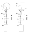
- Figure 6 shows an illustrative top view of the system of Figure 1 with the slit unit further rotated;
- Figure 7 shows an illustrative side view of the system of Figure 1 with the aperture unit and slit unit moved downward;
- Figure 8 shows an illustrative flowchart of a method recording data representative of the illumination field of a line of laser illumination in accordance with an embodiment of the invention;
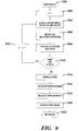
- Figure 9 shows an illustrative flowchart of a method of processing recorded data in accordance with an embodiment of the invention;
- Figure 10 shows a graphical representation of a horizontal profile of an illumination field that was recorded in accordance with an embodiment of the invention;
- Figure 11 shows a graphical representation of a vertical profile of the peak energy and total energy of an illumination field that was recorded in accordance with an embodiment of the invention;
- Figure 12 shows a graphical representation of the fast axis beam width as determined based on each of 1/e2 and full-width-half-max for an illumination field that was recorded in accordance with an embodiment of the invention; and
- Figure 13 shows a graphical representation of a profile with energy thresholds of an illumination field that was recorded in accordance with an embodiment of the invention.
- The drawings are shown for illustrative purposes only, and are not to scale.
- As shown in Figures 1, 2 and 3, a system in accordance with an embodiment of the invention may be used with
laser system 10 that produces a line oflaser illumination 12. In various embodiments, thelaser system 10 may include a variety of optical devices such as micro-lenses and fiber optic cables. The line oflaser illumination 12 is then transmitted through afilter 14 such as a mirror, e.g., a 99% reflecting mirror, to reduce the amount of light that is received by thesensor unit 16. The filtered line oflaser illumination 18 is then passed through anaperture 20 in anaperture unit 22. Aportion 24 of the illumination is then received by a rotatingslit unit 26 that includes a slit opening 28 is its outer wall.
The rotatingslit unit 26 is adapted to rotate as indicated at "A", and the combinedassembly 30 of theaperture unit 22 and the rotatingslit unit 26 is adapted to travel up and down with respect to the laser illumination system as indicated at "B". The laser line of illumination may, for example, be 75 microns by 18 mm. Theaperture 20 may have a width of 150 µm (microns) and a length of 3 mm.
Theslit 28 may have a width of 1 micron and a length of 3 mm. In an embodiment, theaperture 20 is oriented orthogonal to the orientation of the illumination line and is positioned to be at or near the focal plane of the illumination line. Theslit 28 is positioned to be orthogonal to theaperture 20 and parallel with the orientation of the illumination line.
During use, the combinedassembly 30 is moved so that theaperture 20 of theaperture unit 22 is positioned at the top of the filteredillumination field 18. The rotatingslit unit 26 is then rotated so that theslit 28 passes in front of theportion 24 of the illumination field that is transmitted from theaperture unit 22 as shown in Figures 4 and 5. The rotating slit unit then continues rotating as shown in Figure 6 until it completes a full circle. Thesensor unit 16 does not rotate with theslit unit 26, but rather remains in place so that illumination that passes through theslit 28 is received by thesensor unit 16. - As shown in Figure 7, the
assembly 30 is then moved downward by an incremental step (of for example, 100 microns), and the rotating slit unit is then again rotated through a complete cycle. In this fashion, a complete scan of each portion of the line illumination field is recorded.
Specifically, and with reference to Figure 8, the process of recording illumination data (step 800) begins by moving the aperture unit to the top of the illumination field (step 802). The slit unit is then rotated through a complete revolution (step 804). The total energy across the width of the line segment is then recorded (step 806), and the peak energy across the width of the line segment is then recorded (step 808). The aperture unit is then moved down by an incremental step (step 810). If the aperture in the aperture unit is at the bottom of the line illumination field (step 812), then the process ends (step 814), otherwise the process returns tostep 804 and a new set of data is recorded for the current line segment. - As shown in Figure 9, once the data is recorded for the entire line illumination field, the method of analyzing the data begins (step 900) by setting the line segment variable n equal to one (step 902). The Gaussian profile for the nth line segment is then retrieved (step 904), and the peak and distribution for that line segment are recorded (step 906). The beam width is also calculated and recorded (step 908). The above steps 904 - 908 then repeat for each line segment until each segment of the laser line is processed. In particular, if there are more line segments to be processed (step 910), then the variable n is set to be increased by one (step 912), and the process returns to step 904.
After all n line segments have been processed, then the process continues fromstep 910, and the peaks are normalized (step 914). The power uniformity is then calculated (step 916), the width uniformity is then calculated (step 918), and the line length is then calculated (step 920). The process then ends (step 922). The system may then display any of a wide variety of information regarding the illumination field, such as vertical and horizontal profiles, and beam widths and uniformity. - As shown in Figure 10, the composite horizontal profile shows an
illustrative graph 100 of the illumination field in which the x-axis is in microns and the y-axis is adjusted to apply the peak energy to a unitary value. As shown in Figure 11, the vertical profile shows anillustrative graph 110 of the total energy along the illumination line, and shows anillustrative graph 120 of the peak energy along the illumination line. The x-axis of Figure 11 is shown in mm, and the y-axis is unitary as shown in Figure 10. As shown in Figure 11, the difference between the total and peak energy is relatively small, but the uniformity of both the peak and total energies is not less than desirable. The uniformity error, in fact is 20.5% for this sample. The line length is 19.8 mm, and the power within the line is 37 Watts. As shown in Figure 12, the fast axis beam width may be determined based on a limit of 1/e2 (or 13.5%) as shown at 130, or may be determined based on full-width-half-max (or FWHM) as shown at 140. The x-axis is shown in mm and the y-axis is shown in µm. In the 1/e2 graph at 130, the beam width is 78.2 µm, and the variation is 4.15%. In theFWHM graph 140, the beam width is 53.3 µm, and the variation is 14.8%. As shown at Figure 13, a composite illustration of the illumination line may be displayed in which the areas of highest energy are shown inarea 150, areas of less energy are shown inarea 160. Areas of further less energy are shown inarea 170, andarea 180 has the least amount of energy as determined by setting threshold values at, for example, 13.5, 25, 50, 75 and 90%.
Generally the invention relates to a system for analyzing an illumination field (18) of a line of laser illumination (12), said system comprising: - first means (22) for receiving said illumination field (18) and for blocking a first portion of the illumination field (18) and for permitting a second portion (24) of the illumination field (18) to be transmitted through said first means (22), said first means (22) being movable between a first position in which said second portion (24) of the illumination field (18) may be selected to be one end of the illumination field line (18), and a second position in which said second portion (24) of the illumination field (18) may be selected to be the other end of the illumination field line (18);
- sensor means (16) for receiving the second portion (24) of the illumination field (18); and
- second means (26) disposed between said first means (22) and said sensor means (16), said second means (26) for receiving the second portion (24) of the illumination field (18), and for selectively blocking the second portion (24) of the illumination field (18) from reaching said sensor means (16) or permitting the second portion (24) of the illumination field (18) to reach said sensor means (16).
- In the system said first means (22) may include a first elongated opening (20) that is orthogonal to the orientation of the line of laser illumination (12). In the system, said first opening (20) may be moved in a direction (B) that is parallel to the orientation of the line of laser illumination (12).
Said second means (26) may include a second elongated opening (28) that is parallel to the orientation of the line of laser illumination (12).
Said second opening (28) may be moved across the path of the field of laser illumination (18) in a direction that is orthogonal to the orientation of the line of laser illumination (12). - Said first means (22) may include a first elongated opening (20) and said second means (26) may include a second elongated opening (28) that is orthogonal to the orientation of said first elongated opening (20).
- The invention also relates to a system for analyzing an illumination field (18) of a line of laser illumination (12) that is oriented in a first direction and travels along an illumination path in a second direction, said system comprising:
- a first movable unit (22) that includes a first elongated opening (20) through which at least a portion of the illumination field (18) may pass, said first elongated opening (20) being orthogonal to the first direction, and said first movable unit (22) being adapted for movement in a direction (B) that crosses the illumination path and is parallel to the first direction;
- a sensor unit (16) that is adapted to receive illumination (24) and to produce a sensor output signal representative a characteristic of the illumination field (18); and
- a second movable unit (26) that includes a second elongated opening (28) through which at least a portion (24) of the illumination field (18) may pass, said second elongated opening (28) being parallel to the first direction, and said second movable unit (26) being positioned between said first movable unit (22) and said sensor unit (16) and being adapted for movement in a direction (A) that crosses the illumination path in a direction that is orthogonal to the first direction.
- The invention also relates to a method of analyzing an illumination field (18) of a line of laser illumination (12), said method comprising the steps of:
- receiving the illumination field (18) at a first opening (20);
- permitting a portion (24) only of the illumination field (18) to pass through the first opening (20);
- receiving the portion (24) of the illumination field (18) from the first opening (20) at a second opening (28);
- permitting the portion (24) of the illumination field (18) to pass through the second opening (28); and
- moving the second opening (28) such that the portion (24) of the illumination field (18) may not pass through the second opening (28).
- The method may further comprise the step of moving the first opening (20) so that a different portion (24) of the illumination field (18) is permitted to pass through the first opening (20).
The method may further comprise the step of sensing the total and peak energy of at least a portion (24) of the illumination field (18).
The method may further comprise the step of rotating said second opening (28) with respect to a sensor (16). - The system, therefore, may be used to identify numerous qualities of the line of laser illumination, including uniformity of total and peak energy, uniformity in spot size, uniformity in focal points, uniformity at threshold levels, and the length and width of the illumination line.
- Those skilled in the art will appreciate that numerous modifications and variations may be made to the above disclosed embodiments without departing from the scope of the present invention.
Claims (10)
- A system for analyzing an illumination field (18) of a line of laser illumination (12), said system comprising:a first movable unit (22) that includes a first opening (20) through which at least a portion (24) of the illumination field (18) may pass, said first movable unit (22) being adapted for movement in a first direction (B);a sensor unit (16) that is adapted to receive illumination (24) and to produce a sensor output signal representative a characteristic of the illumination field (18); anda second movable unit (26) that includes a second opening (28) through which at least a portion (24) of the illumination field may pass, said second movable unit (26) being positioned between said first movable unit (22) and said sensor unit (16) and being adapted for movement (A) between at least a first position in which very little or no light from said illumination field (18) may reach said sensor unit (16), and a second position in which a relatively high amount of light from said illumination field (18) may reach said sensor unit (16).
- The system according to claim 1, wherein said first opening (20) is elongated in shape and is oriented to be orthogonal to the orientation of the line of laser illumination (12).
- The system according to claims 1 or 2, wherein said second opening (28) is elongated in shape and is oriented to be parallel to the orientation of the line of laser illumination (12).
- The system according to any one of the previous claims, wherein said first movable unit (22) is adapted to move in a direction that is parallel to the orientation of the line of laser illumination (12).
- The system according to any one of the previous claims, wherein said second movable unit (26) is adapted to move the second opening (28) across the path of the illumination field (18) in a second direction that is orthogonal to the orientation of the line of laser illumination (12).
- The system according to any one of the previous claims, wherein said second movable unit (26) is adapted to rotate about a line that is parallel with the line of laser illumination (12) and that crosses the path of the direction of travel of the illumination field (18).
- The system according to any one of the previous claims, wherein said system also includes a filter (14) for reducing the amount of illumination that reaches said first movable unit (22).
- The system according to any one of the previous claims, wherein each of said first (20) and second (28) openings is elongated in shape and orthogonally disposed to one another when aligned with the direction of travel of the illumination field (18).
- The system according to any one of the previous claims, wherein said system is adapted to monitor the peak and total energy of a plurality of segments of the line of laser illumination (12).
- The system according to any one of the previous claims, wherein said first opening (20) is positioned at the focal plane of the illumination field (18).
Applications Claiming Priority (2)
| Application Number | Priority Date | Filing Date | Title |
|---|---|---|---|
| US09/854,612 US6618131B1 (en) | 2001-05-14 | 2001-05-14 | System and method for measuring the quality of an illumination field from a laser line illumination system |
| US854612 | 2001-05-14 |
Publications (1)
| Publication Number | Publication Date |
|---|---|
| EP1260801A1 true EP1260801A1 (en) | 2002-11-27 |
Family
ID=25319160
Family Applications (1)
| Application Number | Title | Priority Date | Filing Date |
|---|---|---|---|
| EP02100493A Ceased EP1260801A1 (en) | 2001-05-14 | 2002-05-14 | System and method for measuring the quality of an illumination field from a laser line illumination system |
Country Status (3)
| Country | Link |
|---|---|
| US (2) | US6618131B1 (en) |
| EP (1) | EP1260801A1 (en) |
| JP (1) | JP2003046176A (en) |
Families Citing this family (3)
| Publication number | Priority date | Publication date | Assignee | Title |
|---|---|---|---|---|
| US20080055590A1 (en) * | 2006-08-31 | 2008-03-06 | Texas Instruments Incorporated | System and method for analyzing a light beam of an exposure tool or a reticle inspection tool |
| US20110317153A1 (en) * | 2010-06-24 | 2011-12-29 | Apple Inc. | Laser peak energy point calibration method and apparatus |
| US8786855B2 (en) * | 2011-01-25 | 2014-07-22 | Ocean Optics, Inc. | Shaped input apertures to improve resolution in grating spectrometers |
Citations (5)
| Publication number | Priority date | Publication date | Assignee | Title |
|---|---|---|---|---|
| FR811143A (en) * | 1935-12-26 | 1937-04-07 | New image exploration system that can be used in television, transmission and reception | |
| EP0319345A2 (en) * | 1987-12-03 | 1989-06-07 | Westinghouse Electric Corporation | High power laser beam intensity mapping apparatus |
| DD268773A1 (en) * | 1988-02-11 | 1989-06-07 | Akad Wissenschaften Ddr | LASER BEAM MEASURING DEVICE FOR HIGH PERFORMANCE LASER |
| FR2663738A1 (en) * | 1990-06-21 | 1991-12-27 | France Etat Armement | Device for analysis of the light intensity within a beam |
| US5459565A (en) * | 1993-08-20 | 1995-10-17 | Duma Optronics, Ltd. | Laser beam analyzer |
Family Cites Families (2)
| Publication number | Priority date | Publication date | Assignee | Title |
|---|---|---|---|---|
| US5078491A (en) * | 1990-04-26 | 1992-01-07 | Coherent, Inc. | Apparatus for measuring the mode quality of a laser beam |
| US5914777A (en) * | 1997-01-20 | 1999-06-22 | Minolta Co., Ltd. | Apparatus for and method of measuring a distribution of luminous intensity of light source |
-
2001
- 2001-05-14 US US09/854,612 patent/US6618131B1/en not_active Expired - Fee Related
-
2002
- 2002-05-08 JP JP2002132619A patent/JP2003046176A/en active Pending
- 2002-05-14 EP EP02100493A patent/EP1260801A1/en not_active Ceased
-
2003
- 2003-04-28 US US10/424,026 patent/US6765660B2/en not_active Expired - Lifetime
Patent Citations (5)
| Publication number | Priority date | Publication date | Assignee | Title |
|---|---|---|---|---|
| FR811143A (en) * | 1935-12-26 | 1937-04-07 | New image exploration system that can be used in television, transmission and reception | |
| EP0319345A2 (en) * | 1987-12-03 | 1989-06-07 | Westinghouse Electric Corporation | High power laser beam intensity mapping apparatus |
| DD268773A1 (en) * | 1988-02-11 | 1989-06-07 | Akad Wissenschaften Ddr | LASER BEAM MEASURING DEVICE FOR HIGH PERFORMANCE LASER |
| FR2663738A1 (en) * | 1990-06-21 | 1991-12-27 | France Etat Armement | Device for analysis of the light intensity within a beam |
| US5459565A (en) * | 1993-08-20 | 1995-10-17 | Duma Optronics, Ltd. | Laser beam analyzer |
Also Published As
| Publication number | Publication date |
|---|---|
| US20030202173A1 (en) | 2003-10-30 |
| US6618131B1 (en) | 2003-09-09 |
| JP2003046176A (en) | 2003-02-14 |
| US6765660B2 (en) | 2004-07-20 |
Similar Documents
| Publication | Publication Date | Title |
|---|---|---|
| JPH08233750A (en) | Infrared-ray light source device for illuminating sensitizing medium | |
| US20100314533A1 (en) | Scanning microscope and method of imaging a sample | |
| CN210220974U (en) | An automatic detection and positioning device for laser spot focus | |
| US7366382B2 (en) | Optical beam diagnostic device and method | |
| EP1301771B1 (en) | Determining optical fiber types | |
| JP2700454B2 (en) | Method and apparatus for characterizing the performance of an optical lens | |
| JP2003344696A (en) | Method, apparatus and system for aligning an end of an optical fiber with an optical waveguide | |
| US20200025609A1 (en) | Rapid Beam Measuring in Several Planes | |
| JP2842310B2 (en) | Optical module optical axis adjusting apparatus and method | |
| US6765660B2 (en) | System and method for measuring the quality of an illumination field from a laser line illumination system | |
| DE19749926A1 (en) | Recording device with laser scanning | |
| JP3162364B2 (en) | Optical sensor device | |
| US4871910A (en) | Method and apparatus for measuring the size of wire rod with laser beam and reference rod | |
| JPS6239365B2 (en) | ||
| DE19703608A1 (en) | Optical waveguide holder for scanning device | |
| JP2008139062A (en) | Spectrometer and method | |
| GB2406905A (en) | An optical beam profile characteriser device using fiber optic bundles | |
| KR102694094B1 (en) | Apparatus for Controlling Camera Interchangeable Lens and Camera Including the Same | |
| JP3243784B2 (en) | Work table positioning device | |
| JP2661430B2 (en) | Optical symbol reader | |
| JPS6288906A (en) | Measuring method for solid shape | |
| JP3602437B2 (en) | Method for determining laser beam focal point position, laser beam focal point position determining device, and hologram laser assembling device | |
| JP2002022427A (en) | 3D image input device | |
| US6882457B1 (en) | System and method for determining the modulation quality of an illumination modulator in an imaging system | |
| JPH07249235A (en) | Astigmatism correction method for semiconductor laser optical system |
Legal Events
| Date | Code | Title | Description |
|---|---|---|---|
| PUAI | Public reference made under article 153(3) epc to a published international application that has entered the european phase |
Free format text: ORIGINAL CODE: 0009012 |
|
| AK | Designated contracting states |
Kind code of ref document: A1 Designated state(s): AT BE CH CY DE DK ES FI FR GB GR IE IT LI LU MC NL PT SE TR |
|
| AX | Request for extension of the european patent |
Free format text: AL;LT;LV;MK;RO;SI |
|
| 17P | Request for examination filed |
Effective date: 20030527 |
|
| 17Q | First examination report despatched |
Effective date: 20030701 |
|
| AKX | Designation fees paid |
Designated state(s): DE FR GB |
|
| STAA | Information on the status of an ep patent application or granted ep patent |
Free format text: STATUS: THE APPLICATION HAS BEEN REFUSED |
|
| 18R | Application refused |
Effective date: 20050314 |