EP1260711A2 - Compressor provided with sliding bearing - Google Patents
Compressor provided with sliding bearing Download PDFInfo
- Publication number
- EP1260711A2 EP1260711A2 EP02011377A EP02011377A EP1260711A2 EP 1260711 A2 EP1260711 A2 EP 1260711A2 EP 02011377 A EP02011377 A EP 02011377A EP 02011377 A EP02011377 A EP 02011377A EP 1260711 A2 EP1260711 A2 EP 1260711A2
- Authority
- EP
- European Patent Office
- Prior art keywords
- sliding bearing
- rotary unit
- housing
- radial sliding
- compressor according
- Prior art date
- Legal status (The legal status is an assumption and is not a legal conclusion. Google has not performed a legal analysis and makes no representation as to the accuracy of the status listed.)
- Withdrawn
Links
Images



Classifications
-
- F—MECHANICAL ENGINEERING; LIGHTING; HEATING; WEAPONS; BLASTING
- F04—POSITIVE - DISPLACEMENT MACHINES FOR LIQUIDS; PUMPS FOR LIQUIDS OR ELASTIC FLUIDS
- F04B—POSITIVE-DISPLACEMENT MACHINES FOR LIQUIDS; PUMPS
- F04B39/00—Component parts, details, or accessories, of pumps or pumping systems specially adapted for elastic fluids, not otherwise provided for in, or of interest apart from, groups F04B25/00 - F04B37/00
-
- F—MECHANICAL ENGINEERING; LIGHTING; HEATING; WEAPONS; BLASTING
- F04—POSITIVE - DISPLACEMENT MACHINES FOR LIQUIDS; PUMPS FOR LIQUIDS OR ELASTIC FLUIDS
- F04B—POSITIVE-DISPLACEMENT MACHINES FOR LIQUIDS; PUMPS
- F04B27/00—Multi-cylinder pumps specially adapted for elastic fluids and characterised by number or arrangement of cylinders
- F04B27/08—Multi-cylinder pumps specially adapted for elastic fluids and characterised by number or arrangement of cylinders having cylinders coaxial with, or parallel or inclined to, main shaft axis
- F04B27/10—Multi-cylinder pumps specially adapted for elastic fluids and characterised by number or arrangement of cylinders having cylinders coaxial with, or parallel or inclined to, main shaft axis having stationary cylinders
- F04B27/1036—Component parts, details, e.g. sealings, lubrication
- F04B27/1054—Actuating elements
- F04B27/1063—Actuating-element bearing means or driving-axis bearing means
-
- F—MECHANICAL ENGINEERING; LIGHTING; HEATING; WEAPONS; BLASTING
- F16—ENGINEERING ELEMENTS AND UNITS; GENERAL MEASURES FOR PRODUCING AND MAINTAINING EFFECTIVE FUNCTIONING OF MACHINES OR INSTALLATIONS; THERMAL INSULATION IN GENERAL
- F16C—SHAFTS; FLEXIBLE SHAFTS; ELEMENTS OR CRANKSHAFT MECHANISMS; ROTARY BODIES OTHER THAN GEARING ELEMENTS; BEARINGS
- F16C2360/00—Engines or pumps
- F16C2360/42—Pumps with cylinders or pistons
Definitions
- the present invention relates to a compressor provided with a sliding bearing which rotatably supports a rotary unit o drive a compression mechanism.
- Japanese Unexamined Patent Publication No. 4-81586 discloses this type of sliding bearing.
- a main shaft functioning as a rotary unit, which transmits rotary force to a pump mechanism of a refrigerant pump is rotatably supported by a bearing bushing functioning as a sliding bearing.
- the bearing bushing is used to rotatably support the main shaft. Manufacturing cost of the bearing bushing is reduced more than that of a rolling bearing. Note that in the prior art the bearing bushing is made of porous ceramic.
- the bearing bushing made of porous ceramic does not have solid lubricating performance.
- the clearance between the bearing bushing and the main shaft is predetermined to be small such that the main shaft is supported by the bearing bushing without rattle, lubricating oil contained in refrigerant scarcely reaches a sliding portion between the bearing bushing and the main shaft. That is, the sliding portion between the bearing bushing and the main shaft tends to be worn. Therefore, lifetime of the bearing bushing is shortened.
- the present invention addresses a compressor with long life which is manufactured at low cost.
- a compressor includes a housing, a compression mechanism, a rotary unit and a sliding bearing.
- the compression mechanism compresses refrigerant in the housing.
- the rotary unit drives the compression mechanism.
- the sliding bearing is supported in the housing while rotatably supporting the rotary unit.
- the sliding bearing has a base member, porous metal layer and fluoro resin layer. The surface of the base member is coated with the porous metal layer having solid lubricating performance. The surface is coated with the fluoro resin layer through the porous metal layer.
- a sliding bearing for rotatably supporting a rotary unit includes a base member, porous metal layer and fluoro resin layer.
- the porous metal layer coats a surface of the base member.
- the porous metal layer has solid lubricating performance.
- the fluoro resin layer coats the surface through the porous metal layer.
- FIG. 1 A single-headed piston type compressor in a vehicle air conditioner according to a first preferred embodiment of the present invention will be described with reference to FIGs. 1 through 3.
- a left side of the drawing is front and a right side of the drawing is rear.
- a cylinder block 11, a front housing 12, a valve plate assembly 13 and a rear housing 14 constitute a housing of a compressor C as a whole or a compressor housing.
- the front housing 12 is secured to the front end of the cylinder block 11.
- the rear housing 14 is secured to the rear end of the cylinder block 11 through the valve plate assembly 13.
- the cylinder block 11 and the front housing 12 define a crank chamber 15.
- a drive shaft 16 is rotatably supported in the compressor housing and extends through the crank chamber 15.
- the front end of the drive shaft 16 is supported in the front housing 12 by a radial sliding bearing 17.
- the radial sliding bearing 17 is fitted into a through hole 12B formed in the front wall 12A of the front housing 12.
- the rear end of the drive shaft 16 is supported in the cylinder block 11 by a radi I sliding bearing 18.
- the radial sliding bearing 18 is fitted into a through hole 11A formed in the cylinder block 11.
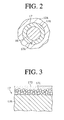
- the radial sliding bearing 17 is formed by bending a flat material in a cylindrical shape such that one end and the other end of the flat material meet with each other at a joint 17A.
- the radial sliding bearing 17 is inserted in the through hole 12B formed in the front wall 12A while supporting the drive shaft 16. In this state, the clearance between the outer circumferential surface of the drive shaft 16 and the inner circumferential surface of the radial sliding bearing 17 is minimized to such an extent that the drive shaft 16 is rotatably supported by the radial sliding bearing 17.
- the clearance between the outer circumferential surface of the radial sliding bearing 17 and the inner circumferential surface of the through hole 12B is designed such that the outer circumferential surface of the radial sliding bearing 17 adheres to the inner circumferential surface of the through hole 12B as much as possible.
- the gap at the joint 17A between the ends of the radial sliding bearing 17 is designed to be as small as possible.
- the base member 17B is made of iron such as SPCC.
- the surface of the base member 17B which is in a flat state is coated with the sintered bronze layer 17C, and then the sintered bronze layer 17C is coated with the fluoro resin layer 17D such that some amount of the fluoro resin layer 17D occupies porosity formed in the sintered bronze layer 17C.
- the thickness of the surface of the fluoro resin layer 17D which has not occupied the porosity and the thickness of the sintered bronze layer 17C are respectively predetermined to be approximately 30 ⁇ m and 220 ⁇ m.
- the radial sliding bearing 18 is constituted in a similar manner other than having small dimensional differential in radial and axial directions from the radial sliding bearing 17. Also, the radial sliding bearing 18 is manufactured in a similar manner.
- the front end of the drive shaft 16 extends outside of the compressor housing through the through hole 12B.
- the front end of the drive shaft 16 directly connects with a vehicle engine E functioning as an external drive source through a power transmission mechanism PT.
- a lip type seal 12C is arranged, thereby preventing the refrigerant in the compressor housing from leaking out of the compressor housing through the through hole 12B.
- a lug plate 19 made of iron is fixedly placed on the drive shaft 16 to integrally rotate with.
- the drive shaft 16 and the lug plate 19 constitute a rotary unit.
- a swash plate 20 functioning as a cam plate is accommodated in the crank chamber 15.
- the swash plate 20 is slidably and inclinably supported on the drive shaft 16 while operatively connects with the lug plate 19 through a hinge mechanism 21. Therefore, the swash plate 20 rotates synchronously with the lug plate 19 and the drive shaft 16, and is slidable along the axis of the drive shaft 16 and is inclinable with respect to the axis.
- a circular clip 22 engages with the drive shaft 16.
- a spring 23 is arranged between the swash plate 20 and the circular clip 22. The spring 23 regulates inclination angle of the swash plate 20 with respect to the perpendicular plane to the drive shaft 16. That is, the spring 23 regulates the minimum inclination angle of the swash plate 20.
- a plurality of cylinder bores 24 is formed through the cylinder block 11 to surround the drive shaft 16, although only one cylinder bore 24 is illustrated in FIG. 1.
- a single-headed piston 25 is accommodated in each of the cylinder bores 24 to be reciprocated.
- a compression chamber as a compression region is defined between the piston 25 and the valve plate assembly 13.
- Front side of the piston 25 engages with the outer circumference of the swash plate 20 through a pair of shoes 26. Accordingly, as the drive shaft 16 is rotated, the movement in the direction of the axis at the distal end of the swash plate 20 is transmitted to the piston 25 through the shoes 26. Consequently, the piston 25 is reciprocated in each of the cylinder bores 24.
- the piston 25, the shoes 26, the swash plate 20, the hinge mechanism 21 and the lug plate 19 constitute a crank mechanism.
- the crank mechanism, the cylinder block 11 including the cylinder bores 24, and the drive shaft 16 constitute a compression mechanism.
- a thrust rolling bearing 27A is placed between the lug plate 19 and the front wall 12A of the front housing 12.
- the thrust rolling bearing 27A supports the rotary unit in a thrust direction, thereby receiving the compression reactive force acting on the lug plate 19.
- a thrust rolling bearing 27B is accommodated in the through hole 11A.
- a second circular clip 22A engages with the cylinder block 11.
- a second spring 23A is interposed between the thrust rolling bearing 27B and the second circular clip 22A.
- the cylinder block 11 supports the rear end of the drive shaft 16 through the thrust rolling bearing 27B, the second spring 23A and the second circular clip 22A, thereby restraining the rear end of the drive shaft 16 from moving rearward.
- a suction chamber 28 and a discharge chamber 29 are defined between the valve plate assembly 13 and the rear housing 14.
- Refrigerant in the suction chamber 28 is drawn into the cylinder bore 24 through a suction port 13A formed on the valve plate assembly 13 by pushing away a suction valve 13B formed on the valve plate assembly 13 while the piston 25 moves from a top dead center to a bottom dead center.
- the refrigerant drawn into the cylinder bore 24 is compressed to a predetermined pressure level while the piston 25 moves from the bottom dead center to the top dead center.
- the compressed refrigerant is introduced into the discharge chamber 29 through a discharge port 13C formed on the valve plate assembly 13 by pushing away a discharge valve 13E formed on the valve plate assembly 13.
- the suction chamber 28 connects with the discharge chamber 29 through an external refrigerant circuit 30.
- the external refrigerant circuit 30 mainly includes a condenser 31, a thermal expansion valve 32 as a decompression device, and an evaporator 33.
- the opening degree of the thermal expansion valve 32 is controlled based on the temperature and pressure detected in a temperature reacting pipe 34 attached toward the outlet or downstream of the evaporator 33.
- the thermal expansion valve 32 supplies the liquid refrigerant of which amount corresponds to cooling load, to the evaporator 33, thereby adjusting the amount of refrigerant circulated in the external refrigerant circuit 30.
- the outlet of the evaporator 33 connects with the suction chamber 28 in the compressor C through a first circulation pipe 35.
- the discharge chamber 29 in the compressor C connects with an inlet of the condenser 31 through a second circulation pipe 36.
- the refrigerant in the discharge chamber 29 is introduced into the external refrigerant circuit 30.
- heat exchange is performed by utilizing the refrigerant.
- the refrigerant in the external refrigerant circuit 30 is introduced into the suction chamber 28 and drawn into the compression chamber in the cylinder bore 24 and compressed therein and discharged into the discharge chamber 29. This cycle is repeated.
- a bleed passage 37 is formed to connect the crank chamber 15 to the suction chamber 28.
- a supply passage 38 is formed to connect the discharge chamber 29 to the crank chamber 15.
- a control valve 39 is arranged in the supply passage 38, thereby adjusting the opening degree of the supply passage 38.
- crank chamber 15 The refrigerant in the discharge chamber 29 tends to flow into the crank chamber 15 through the supply passage 38. At the same time, the refrigerant in the crank chamber 15 tends to flow into the suction chamber 28 through the bleed passage 37.
- Pressure Pc in the crank chamber 15 or crank pressure Pc is determined by adjusting the opening degree of the control valve 39.
- the pressure differential between the crank pressure Pc and the pressure in the compression chamber, which applied to the piston 25, is varied in accordance with the crank pressure Pc.
- inclination angle of the swash plate 20 is varied and an amount of stroke of the piston 25 is also varied. Accordingly, displacement is adjusted.
- the suction chamber 28, the suction port 13A, the cylinder bore 24, the discharge port 13C and the discharge chamber 29 constitute a refrigerant route in the compressor housing.
- the drive shaft 16 slides with respect to the fluoro resin layer 17D of the radial sliding bearing 17, which has solid lubricating performance. Therefore, the drive shaft 16 is scarcely worn. Even if the fluoro resin layer 17D is worn, the radial sliding bearing 17 exposes the sintered bronze layer 17C, which also has solid lubricating performance. Therefore, the drive shaft 16 slides with respect to the sintered bronze layer 17C of the radial sliding bearing 17. Accordingly, the drive shaft 16 slides with respect to the radial sliding bearing 17, thereby being maintained so as not to be worn. In a similar manner, the drive shaft 16 slides with respect to the radial bearing 18, thereby being maintained so as not to be worn.
- the first plate 42 may be fixed to the front wall 12A so as to directly slidably contact with the lug plate 19.
- the second plate 43 may be omitted. Therefore, the manufacturing cost may be reduced more.
- a thrust sliding bearing may be arranged in place of the thrust rolling bearing 27B so as to restrain the drive shaft 16 from moving rearward.
- the radial sliding bearings 17,18 and the thrust sliding bearing 41 are employed as a sliding bearing.
- the thrust sliding bearing 41 alone may be employed as a sliding bearing.
- a thrust sliding bearing which has a similar constitution to the thrust sliding bearing 41 of the second embodiment, may be employed in place of the thrust rolling bearing 62 so as to regulate the drive shaft 57 and the swash plate 60 in the thrust direction. In this case, the manufacturing cost is reduced more.
- the radial sliding bearings 17 and 18 are employed as a sliding bearing.
- the thrust sliding bearing 41 of the second embodiment which is used in place of the thrust rolling bearing 62 alone may be employed as a sliding bearing.
- the clearances between the outer circumferential surfaces of the drive shafts 16, 57 and the inner circumferential surfaces of the radial sliding bearings 17, 18 are not required to be minimized to such an extent that the drive shafts 16, 57 are rotatably supported by the radial sliding bearings 17, 18.
- the clearances may be predetermined to become large to such an extent that the drive shafts 16, 57 are rotatably supported by the radial sliding bearings 17, 18.
- the clearance between the outer circumferential surface of the radial sliding bearing 17 and the inner circumferential surfaces of the through hole 12B and the support hole 51A are designed such that the outer circumferential surface of the radial sliding bearing 17 adheres to the inner circumferential surfaces of the through hole 12B and the support hole 51 A as much as possible.
- the gap between the ends of the radial sliding bearing 17 is designed to be as small as possible.
- the outer circumferential surface of the radial sliding bearing 17 is not required to adhere to the inner circumferential surfaces of the through hole 12B and the support hole 51 A.
- the gap between the ends of the radial sliding bearing 17 may be designed to become large to such an extent that the drive shafts 16, 57 are rotatably supported by the radial sliding bearing 17.
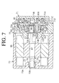
- a clearance between the boss 80C and the bushing 82, a clearance between the bushing 82 and the radial sliding bearing 81, and a clearance between the radial sliding bearing 81 and the crankshaft 74A may be formed to allow the refrigerant to flow between the discharge chamber 89 and the space 91.
- the clearance between the through hole 72E and the radial sliding bearing 75 and the clearance between the radial sliding bearing 75 and the shaft 74 may be formed to allow the refrigerant to flow between the motor chamber 78 and the space 91.
- the radial sliding bearings 75, 76 and 81 are employed as a sliding bearing.
- either the radial sliding bearings 75 and 76 or the radial sliding bearing 81 may be employed as a sliding bearing.
- fluoro resin layer may be employed other than PTFE.
- porous metal layer such as lead which has solid lubricating performance may be employed other than bronze.
- lead In view of environment, lead should be restrained from being employed as much as possible.
- an iron plate for use in a base member of the radial sliding bearings 17, 18, 75, 76 and 81 are employed other than SPCC.
- the radial sliding bearings 17, 18, 75, 76 and 81 are formed by bending an iron plate.
- method for forming the radial sliding bearings 17, 18, 75, 76 and 81 is not limited to the above method.
- a base member may be formed in a cylindrical shape by casting and then the inner circumferential surface of the cylindrical base member may be coated with fluoro resin layer through porous metal layer.
- a compressor includes a housing, a compression mechanism, a rotary unit and a sliding bearing.
- the compression mechanism compresses refrigerant in the housing.
- the rotary unit drives the compression mechanism.
- the sliding bearing is supported in the housing while rotatably supporting the rotary unit.
- the sliding bearing has a base member, porous metal layer and fluoro resin layer. The surface of the base member is coated with the porous metal layer having solid lubricating performance. The surface is coated with the fluoro resin layer through the porous metal layer.
Landscapes
- Engineering & Computer Science (AREA)
- Mechanical Engineering (AREA)
- General Engineering & Computer Science (AREA)
- Compressor (AREA)
- Sliding-Contact Bearings (AREA)
- Compressors, Vaccum Pumps And Other Relevant Systems (AREA)
- Applications Or Details Of Rotary Compressors (AREA)
Abstract
Description
Claims (24)
- A compressor comprising:a housing;a compression mechanism in the housing for compressing refrigerant;a rotary unit for driving the compression mechanism; anda sliding bearing supported in the housing, the sliding bearing rotatably supporting the rotary unit, the sliding bearing including;a base member,porous metal layer for coating a surface of the base member, the porous metal layer having solid lubricating performance, andfluoro resin layer for coating the surface through the porous metallayer.
- The compressor according to claim 1 wherein the sliding bearing is a radial sliding bearing which supports the rotary unit in a radial direction.
- The compressor according to claim 1 wherein the sliding bearing is a thrust sliding bearing which supports the rotary unit in a thrust direction, and wherein the thrust sliding bearing is arranged so as to receive compression reactive force generated by the compression mechanism through the rotary unit.
- The compressor according to claim 1 wherein the sliding bearing separates inside of the housing in pressure.
- The compressor according to claim 1 wherein the porous metal layer is made of bronze.
- The compressor according to claim 1 wherein the fluoro resin layer is PTFE.
- The compressor according to claim 1 wherein the porous metal layer is sintered bronze layer and the fluoro resin layer is PTFE and wherein the thickness of the surface of the PTFE which has not occupied porosity formed in the sintered bronze layer and the thickness of the sintered bronze layer are respectively predetermined to be approximately 30 µm and 220 µm.
- The compressor according to claim 1 wherein the rotary unit is made of iron.
- The compressor according to claim 1 wherein the base member is made of iron.
- The compressor according to claim 1 wherein the compression mechanism includes a plurality of cylinder bores, a piston accommodated in each of the cylinder bores, and a crank mechanism for reciprocating the piston in each of the cylinder bores based on rotation of the rotary unit, the housing including a crank chamber for accommodating the crank mechanism and the sliding bearing, the refrigerant compressed by the compression mechanism being introduced into the crank chamber, a stroke amount of the piston being varied by adjusting pressure in the crank chamber.
- The compressor according to claim 10 wherein the piston is a single-headed piston, the crank mechanism including a hinge mechanism, rotation of the rotary unit being transmitted to the single-headed piston through the hinge mechanism by the crank mechanism.
- The compressor according to claim 1 wherein the compression mechanism includes a plurality of cylinder bores, a piston accommodated in each of the cylinder bores, and a crank mechanism for reciprocating the piston in each of the cylinder bores based on rotation of the rotary unit, the housing including a crank chamber for accommodating the crank mechanism and the sliding bearing, the crank chamber constituting a refrigerant route in the housing.
- The compressor according to claim 12 wherein the piston is a double-headed piston for compressing the refrigerant at both ends of the piston, the crank mechanism being arranged between the ends.
- The compressor according to claim 1 wherein the compression mechanism is a scroll type compression mechanism.
- The compressor according to claim 14 further comprising an electric motor for driving the scroll type compression mechanism.
- The compressor according to claim 1 wherein the rotary unit includes at least one of a drive shaft, a lug plate and a swash plate.
- A sliding bearing for rotatably supporting a rotary unit comprising;a base member,porous metal layer for coating a surface of the base member, the porous metal layer having solid lubricating performance, andfluoro resin layer for coating the surface through the porous metal layer.
- The sliding bearing according to claim 17 wherein the sliding bearing is a radial sliding bearing which supports the rotary unit in a radial direction.
- The sliding bearing according to claim 17 wherein the sliding bearing is a thrust sliding bearing which supports the rotary unit in a thrust direction.
- The sliding bearing according to claim 17 wherein the porous metal layer is made of bronze.
- The sliding bearing according to claim 17 wherein the fluoro resin layer is PTFE.
- The sliding bearing according to claim 17 wherein the porous metal layer is sintered bronze layer and the fluoro resin layer is PTFE.
- The sliding bearing according to claim 17 wherein the rotary unit is made of iron.
- The sliding bearing according to claim 17 wherein the base member is made of iron.
Applications Claiming Priority (2)
| Application Number | Priority Date | Filing Date | Title |
|---|---|---|---|
| JP2001155601A JP2002349437A (en) | 2001-05-24 | 2001-05-24 | Compressor |
| JP2001155601 | 2001-05-24 |
Publications (2)
| Publication Number | Publication Date |
|---|---|
| EP1260711A2 true EP1260711A2 (en) | 2002-11-27 |
| EP1260711A3 EP1260711A3 (en) | 2004-04-28 |
Family
ID=18999759
Family Applications (1)
| Application Number | Title | Priority Date | Filing Date |
|---|---|---|---|
| EP02011377A Withdrawn EP1260711A3 (en) | 2001-05-24 | 2002-05-23 | Compressor provided with sliding bearing |
Country Status (6)
| Country | Link |
|---|---|
| US (1) | US20020176785A1 (en) |
| EP (1) | EP1260711A3 (en) |
| JP (1) | JP2002349437A (en) |
| KR (1) | KR20020090108A (en) |
| CN (1) | CN1388319A (en) |
| BR (1) | BR0201920A (en) |
Cited By (2)
| Publication number | Priority date | Publication date | Assignee | Title |
|---|---|---|---|---|
| EP2071202A4 (en) * | 2006-09-28 | 2012-12-05 | Daikin Ind Ltd | SLIDING ELEMENT AND FLUID MACHINE THEREWITH |
| CN114109431A (en) * | 2021-11-30 | 2022-03-01 | 中国煤炭科工集团太原研究院有限公司 | Flexible connection structure of outer telescopic mechanism for whole-rock tunneling machine |
Families Citing this family (13)
| Publication number | Priority date | Publication date | Assignee | Title |
|---|---|---|---|---|
| WO2006135112A1 (en) * | 2005-06-17 | 2006-12-21 | Showa Denko K.K. | Upsetting method and upsetting apparatus |
| JP2007276764A (en) * | 2006-03-13 | 2007-10-25 | Ntn Corp | Bearing device for drive wheel |
| US20080226471A1 (en) * | 2007-03-12 | 2008-09-18 | Kabushiki Kaisha Toyota Jidoshokki | Variable displacement compressor |
| EP1975424A1 (en) | 2007-03-29 | 2008-10-01 | Saint-Gobain Performance Plastics Pampus Gmbh | Sliding bearing material which can be calibrated |
| JP2009133329A (en) * | 2007-11-28 | 2009-06-18 | Daikin Ind Ltd | Bearing member and compressor |
| JP2012193926A (en) * | 2011-03-17 | 2012-10-11 | Sumitomo Heavy Ind Ltd | Cryogenic refrigerator |
| JP5938217B2 (en) * | 2012-01-16 | 2016-06-22 | Ntn株式会社 | Compressor plain bearings and compressors |
| WO2013022094A1 (en) * | 2011-08-11 | 2013-02-14 | Ntn株式会社 | Sliding nut, sliding bearing for compressor, and cradle guide |
| JP2014230570A (en) * | 2013-05-28 | 2014-12-11 | 室本鉄工株式会社 | Cutting tool and method for production thereof |
| KR102118595B1 (en) * | 2015-04-24 | 2020-06-04 | 한온시스템 주식회사 | Method for manufacturing cylinder block and Double-headed swash plate type compressor |
| JPWO2019176724A1 (en) * | 2018-03-14 | 2021-02-25 | 株式会社ヴァレオジャパン | Slanted plate compressor |
| US10753392B2 (en) | 2018-06-11 | 2020-08-25 | Trane International Inc. | Porous gas bearing |
| US10774873B2 (en) | 2018-06-11 | 2020-09-15 | Trane International Inc. | Porous gas bearing |
Family Cites Families (6)
| Publication number | Priority date | Publication date | Assignee | Title |
|---|---|---|---|---|
| JP2512150B2 (en) * | 1989-05-31 | 1996-07-03 | 松下電器産業株式会社 | Refrigeration air conditioning scroll compressor |
| JPH0653932B2 (en) * | 1989-07-28 | 1994-07-20 | トヨタ自動車株式会社 | Sliding member |
| JPH0735513B2 (en) * | 1990-02-27 | 1995-04-19 | 大同メタル工業株式会社 | Sliding member and manufacturing method thereof |
| JP2868296B2 (en) * | 1990-07-20 | 1999-03-10 | 松下電器産業株式会社 | Refrigerant pump |
| JPH0960586A (en) * | 1995-08-21 | 1997-03-04 | Toyota Autom Loom Works Ltd | Cam plate-type double ended compressor |
| JP3627467B2 (en) * | 1997-09-11 | 2005-03-09 | 株式会社日立製作所 | Refrigerant compressor and refrigeration system |
-
2001
- 2001-05-24 JP JP2001155601A patent/JP2002349437A/en active Pending
-
2002
- 2002-03-18 KR KR1020020014524A patent/KR20020090108A/en not_active Ceased
- 2002-05-23 EP EP02011377A patent/EP1260711A3/en not_active Withdrawn
- 2002-05-23 CN CN02120495A patent/CN1388319A/en active Pending
- 2002-05-23 BR BR0201920-5A patent/BR0201920A/en not_active IP Right Cessation
- 2002-05-23 US US10/154,288 patent/US20020176785A1/en not_active Abandoned
Cited By (3)
| Publication number | Priority date | Publication date | Assignee | Title |
|---|---|---|---|---|
| EP2071202A4 (en) * | 2006-09-28 | 2012-12-05 | Daikin Ind Ltd | SLIDING ELEMENT AND FLUID MACHINE THEREWITH |
| CN114109431A (en) * | 2021-11-30 | 2022-03-01 | 中国煤炭科工集团太原研究院有限公司 | Flexible connection structure of outer telescopic mechanism for whole-rock tunneling machine |
| CN114109431B (en) * | 2021-11-30 | 2023-07-25 | 中国煤炭科工集团太原研究院有限公司 | Flexible connection structure of external extension mechanism for all-rock development machine |
Also Published As
| Publication number | Publication date |
|---|---|
| BR0201920A (en) | 2003-04-22 |
| JP2002349437A (en) | 2002-12-04 |
| KR20020090108A (en) | 2002-11-30 |
| CN1388319A (en) | 2003-01-01 |
| US20020176785A1 (en) | 2002-11-28 |
| EP1260711A3 (en) | 2004-04-28 |
Similar Documents
| Publication | Publication Date | Title |
|---|---|---|
| EP2131040B1 (en) | Motor-driven scroll type compressor | |
| US7556483B2 (en) | Electronic compressor having a reservoir chamber and an oil return passage for connecting the reservoir chamber with a suction chamber | |
| US6565329B2 (en) | Electric type swash plate compressor | |
| US7264453B2 (en) | Horizontal scroll compressor having a connecting passage on the opposite side of a suction port for connecting a motor accommodating chamber with a suction chamber | |
| US5823294A (en) | Lubrication mechanism in compressor | |
| US20020176785A1 (en) | Compressor provided with sliding bearing | |
| JP3282457B2 (en) | Single-head piston type compressor | |
| KR102913725B1 (en) | Low pressure chamber rotary compressor and air conditioner | |
| JP2004138059A (en) | Horizontal type two-stage rotary compressor | |
| US6862975B2 (en) | Apparatus for lubricating piston type compressor | |
| US6589022B2 (en) | Compressor having a seal cooling structure in which all refrigerant fluid supplied to the compressor is used to cool compressor shaft seals | |
| US20040265144A1 (en) | Hybrid compressor | |
| US20020079647A1 (en) | Mechanical seal with embedded lubrication | |
| EP1167763A2 (en) | Variable displacement swash plate compressor | |
| CN111656012A (en) | Variable capacity swash plate compressor | |
| JPH0979153A (en) | High pressure dome compressor | |
| JP2005016379A (en) | Scroll type fluid machinery | |
| JP3735996B2 (en) | Swash plate compressor | |
| KR100748140B1 (en) | Thrust Bearing Support Structure for Drive Shaft of Variable Capacity Swash Plate Compressor | |
| EP1772627B1 (en) | A sealing system for a compressor | |
| US11994119B2 (en) | Compressor | |
| JP3666170B2 (en) | Swash plate compressor | |
| JP2017150315A (en) | Variable displacement swash plate compressor | |
| JP2587484Y2 (en) | Swash plate compressor | |
| JP2587488Y2 (en) | Swash plate compressor |
Legal Events
| Date | Code | Title | Description |
|---|---|---|---|
| PUAI | Public reference made under article 153(3) epc to a published international application that has entered the european phase |
Free format text: ORIGINAL CODE: 0009012 |
|
| 17P | Request for examination filed |
Effective date: 20020523 |
|
| AK | Designated contracting states |
Kind code of ref document: A2 Designated state(s): AT BE CH CY DE DK ES FI FR GB GR IE IT LI LU MC NL PT SE TR |
|
| AX | Request for extension of the european patent |
Free format text: AL;LT;LV;MK;RO;SI |
|
| PUAL | Search report despatched |
Free format text: ORIGINAL CODE: 0009013 |
|
| AK | Designated contracting states |
Kind code of ref document: A3 Designated state(s): AT BE CH CY DE DK ES FI FR GB GR IE IT LI LU MC NL PT SE TR |
|
| AX | Request for extension of the european patent |
Extension state: AL LT LV MK RO SI |
|
| RIC1 | Information provided on ipc code assigned before grant |
Ipc: 7B 32B 15/20 B Ipc: 7B 32B 15/18 B Ipc: 7B 32B 27/00 B Ipc: 7F 04C 29/00 B Ipc: 7F 04C 18/02 B Ipc: 7F 04B 27/10 A |
|
| AKX | Designation fees paid |
Designated state(s): DE FR IT |
|
| STAA | Information on the status of an ep patent application or granted ep patent |
Free format text: STATUS: THE APPLICATION IS DEEMED TO BE WITHDRAWN |
|
| 18D | Application deemed to be withdrawn |
Effective date: 20041201 |