EP1260690B1 - System and method for monitoring gas turbine engine starting systems - Google Patents
System and method for monitoring gas turbine engine starting systems Download PDFInfo
- Publication number
- EP1260690B1 EP1260690B1 EP02253389A EP02253389A EP1260690B1 EP 1260690 B1 EP1260690 B1 EP 1260690B1 EP 02253389 A EP02253389 A EP 02253389A EP 02253389 A EP02253389 A EP 02253389A EP 1260690 B1 EP1260690 B1 EP 1260690B1
- Authority
- EP
- European Patent Office
- Prior art keywords
- data
- engine
- gas turbine
- starting system
- engine starting
- Prior art date
- Legal status (The legal status is an assumption and is not a legal conclusion. Google has not performed a legal analysis and makes no representation as to the accuracy of the status listed.)
- Expired - Lifetime
Links
- 238000012544 monitoring process Methods 0.000 title claims description 28
- 238000000034 method Methods 0.000 title claims description 16
- 239000000446 fuel Substances 0.000 claims description 15
- 238000005070 sampling Methods 0.000 claims description 13
- 239000007858 starting material Substances 0.000 claims description 10
- 230000000977 initiatory effect Effects 0.000 claims description 6
- 239000007789 gas Substances 0.000 description 18
- 238000012423 maintenance Methods 0.000 description 5
- 238000012545 processing Methods 0.000 description 3
- 238000013459 approach Methods 0.000 description 2
- 238000013480 data collection Methods 0.000 description 2
- 238000013500 data storage Methods 0.000 description 2
- 238000013154 diagnostic monitoring Methods 0.000 description 2
- 238000010586 diagram Methods 0.000 description 2
- 239000000284 extract Substances 0.000 description 2
- 230000015556 catabolic process Effects 0.000 description 1
- 239000000567 combustion gas Substances 0.000 description 1
- 238000004891 communication Methods 0.000 description 1
- 238000006731 degradation reaction Methods 0.000 description 1
- 239000000203 mixture Substances 0.000 description 1
- 230000003287 optical effect Effects 0.000 description 1
- 238000012216 screening Methods 0.000 description 1
- 238000012546 transfer Methods 0.000 description 1
Images

Classifications
-
- F—MECHANICAL ENGINEERING; LIGHTING; HEATING; WEAPONS; BLASTING
- F02—COMBUSTION ENGINES; HOT-GAS OR COMBUSTION-PRODUCT ENGINE PLANTS
- F02C—GAS-TURBINE PLANTS; AIR INTAKES FOR JET-PROPULSION PLANTS; CONTROLLING FUEL SUPPLY IN AIR-BREATHING JET-PROPULSION PLANTS
- F02C7/00—Features, components parts, details or accessories, not provided for in, or of interest apart form groups F02C1/00 - F02C6/00; Air intakes for jet-propulsion plants
- F02C7/26—Starting; Ignition
-
- F—MECHANICAL ENGINEERING; LIGHTING; HEATING; WEAPONS; BLASTING
- F02—COMBUSTION ENGINES; HOT-GAS OR COMBUSTION-PRODUCT ENGINE PLANTS
- F02N—STARTING OF COMBUSTION ENGINES; STARTING AIDS FOR SUCH ENGINES, NOT OTHERWISE PROVIDED FOR
- F02N11/00—Starting of engines by means of electric motors
-
- F—MECHANICAL ENGINEERING; LIGHTING; HEATING; WEAPONS; BLASTING
- F05—INDEXING SCHEMES RELATING TO ENGINES OR PUMPS IN VARIOUS SUBCLASSES OF CLASSES F01-F04
- F05D—INDEXING SCHEME FOR ASPECTS RELATING TO NON-POSITIVE-DISPLACEMENT MACHINES OR ENGINES, GAS-TURBINES OR JET-PROPULSION PLANTS
- F05D2220/00—Application
- F05D2220/50—Application for auxiliary power units (APU's)
Definitions
- This invention relates generally to gas turbine engines and more particularly to monitoring engine starting system performance in such engines.
- Gas turbine engines are used for a wide variety of aeronautical, marine and industrial applications.
- a gas turbine engine includes a compressor that provides pressurized air to a combustor, wherein the air is mixed with fuel and the mixture is ignited for generating hot combustion gases. These gases flow downstream to a turbine section that extracts energy therefrom to drive the compressor and provide useful work.
- gas turbine engines are routinely subject to various maintenance procedures as part of their normal operation.
- monitoring systems are often employed to provide diagnostic monitoring of the gas turbine engine. These systems commonly include performance monitoring equipment that collects relevant trend and fault data used for diagnostic trending.
- process data such as exhaust gas temperature, fuel flow, rotor speed and the like
- process data that are indicative of overall engine performance and/or condition are compared to -a parametric baseline for the gas turbine engine. Any divergence of the raw trend data from the parametric baseline may be indicative of a present or future condition that requires maintenance.
- modern aircraft currently operated by commercial airlines typically employ an onboard data acquisition system for collecting digital flight data to use in diagnostic monitoring.
- a number of sensors distributed throughout the aircraft and engines provide data signals representative of the performance of the aircraft and its engines.
- Such data can be recorded onboard and accessed later by ground maintenance personnel or, alternatively, can be remotely transmitted to ground locations during flight operations for real-time processing.
- Engine condition monitoring techniques typically use a screening process to identify various phases of operation and then extract specific data during the flight phases of interest.
- data collection is conducted during flight phases such as take off, climb and steady cruise, because these are the phases during which engine anomalies are most likely to be detected. While these approaches work quite well in detecting anomalies in the primary engine components, they are not as effective in monitoring the condition of the engine starting system components. Being able to predict maintenance needs in engine starting systems will greatly enhance reliability and dispatchability.
- US-A-5 748 500 discloses an engine monitoring system and method with the preamble of claims 1 and 7.
- the present invention provides a method and system for monitoring engine starting system performance in a gas turbine engine in which a plurality of sensors used to sense data related to the operation and performance of the gas turbine engine. Selected data parameters from the sensed data are continuously sampled during an engine start sequence. The data parameters are then evaluated to determine whether predetermined sets of criteria have been met, and selected engine starting system performance data are captured when each of the sets of criteria are met. The captured engine starting system performance data are normalized and then compared to a parametric baseline for the gas turbine engine.
- Figure 1 shows a block diagram of system 10 for monitoring the condition of the engine starting system in a gas turbine engine 12 mounted on an aircraft 14.
- a gas turbine engine 12 mounted on an aircraft 14.
- the aircraft 14 could have additional engines mounted thereon.
- data collection for such additional engines would be accomplished in a manner identical to that for engine 12. Therefore, only the engine 12 and its associated equipment will be described herein.
- the engine 12 is described in connection with an aircraft only by way of example.
- the present invention is applicable to other applications of gas turbine engines, including marine and industrial applications.
- the system 10 includes an electronic control unit (ECU) 16, such as a full authority digital engine control (FADEC) although other controllers can be used and an onboard aircraft data box 18.
- ECU electronice control unit
- FADEC full authority digital engine control
- a set of conventional engine data sensors 20 and aircraft data sensors 21 is distributed throughout the engine 12 and aircraft 14 to sense selected data parameters related to the operation and performance of the engine 12 and/or the aircraft 14.
- the engine data sensors 20 and aircraft data sensors 21 can comprise any group of sensors that monitor data parameters of interest.
- engine parameters would typically include exhaust gas temperature, engine fuel flow, core speed, compressor discharge pressure, turbine exhaust pressure, fan speed, and the like.
- the ECU 16 receives signals from the engine data sensors 20 and aircraft data sensors 21 as is known in the art.
- the ECU 16 also receives a thrust request signal from a throttle 22 controlled by the aircraft's pilot.
- the ECU 16 generates command signals to operate engine actuators, such as a hydromechanical unit (HMU) 24 that meters the flow of fuel to the engine 12.
- the HMU 24 is a unit that is well known to those skilled in the art.
- the ECU 16 also outputs data signals to the aircraft data box 18.
- the aircraft data box 18 also receives signals from the aircraft data sensors 21.
- the engine 12 includes an engine starting system having an engine turbine starter that is mounted on the engine's gearbox.
- an engine turbine starter that is mounted on the engine's gearbox.
- high pressure auxiliary air is delivered to the starter, which causes the engine core to rotate via the gearbox.
- the ECU 16 schedules fuel delivery and variable geometry adjustments to complete the engine start sequence and bring the engine 12 to idle operating condition.
- the source of auxiliary air is an auxiliary power unit (APU) which is usually located in the tail of an aircraft 14, a ground cart, or cross bleed from another engine.
- APU auxiliary power unit
- the system 10 includes an algorithm that processes the data signals to monitor engine starting system performance characteristics.
- the monitoring algorithm can be implemented in a number of ways.
- the monitoring algorithm could be implemented on the ECU 16 wherein the data signals are processed as they are received by the ECU 16.
- the monitoring algorithm could be implemented on the aircraft data box 18. In this case, the data signals would be processed after being transferred to the aircraft data box 18.
- a ground station computer 26 such as personal or workstation computer. The data signals stored in the aircraft data box 18 during a flight are downloaded to the ground station computer for processing.
- This transfer can be accomplished after the flight via any sort of link 28 including use of a removable computer-readable medium, such as a floppy disk, CD-ROM or other optical medium, magnetic tape or the like, or a wireless communication link. It is also possible to remotely transmit the data signals directly to the ground station computer 26 during flight operations for real-time processing.
- the monitoring algorithm can be stored on the unit (be it the ECU, aircraft data box or ground station computer) and accessed from there, or alternatively, it could be accessed from a removable computer-readable medium inserted into the appropriate drive of the unit. The monitoring algorithm could also be accessed via the Internet or another computer network.
- the term "computer-readable medium” refers generally to any medium from which stored data can be read by a computer or similar unit. This includes not only removable media such as the aforementioned floppy disk and CD-ROM, but also non-removable media such as a hard disk or integrated circuit memory device in the ECU 16, aircraft data box 18 or ground station computer 26.
- the algorithm is initiated whenever an engine start sequence is begun.
- the first step shown at block 100, is to continuously monitor the output of the engine data sensors 20 and aircraft data sensors 21.
- selected data parameters sensed by the engine data sensors 20 and aircraft data sensors 21 are continuously sampled.
- the data parameters are sampled at a high frequency, such as every 30-60 milliseconds, to collect a large volume of data points.
- Which data parameters are sampled can vary depending on a number of factors.
- the monitoring algorithm will be described herein with core speed, fuel flow, exhaust gas temperature (EGT) jump, compressor discharge pressure (PS3) jump, and peak exhaust gas temperature as the selected data parameters.
- EHT exhaust gas temperature
- PS3 compressor discharge pressure
- peak exhaust gas temperature peak exhaust gas temperature
- each selected data parameter is evaluated to determine whether specific criteria have been met, as denoted at blocks 104-110.
- the purpose of this portion of the monitoring algorithm is to identify certain phases or times in the engine start sequence for monitoring engine starting system performance characteristics. In each instance, if the criteria are met at any of blocks 104-110, then the monitoring algorithm proceeds to block 112 where selected engine starting performance data and time when the criteria are met are captured and stored. That is, as each particular set of decision criteria is met, current engine and aircraft data are captured and stored with the corresponding data sampling time. If the criteria are not met at any of blocks 104-110, then the monitoring algorithm returns to block 102 so that the data parameters are continually sampled until the criteria for each of the blocks 104-110 have been met.
- each decision block 104-110 captures data at a different phase or time of the engine start sequence. More specifically, the initiation decision criteria of block 104 are such that data are captured when the engine start sequence is first initiated. For example, the initiation decision criteria could be: 1) the starter valve is open. If this sole criterion is met (indicating that the engine start sequence has begun), then the pertinent engine and aircraft data at that specific time are captured and stored at block 112.
- the start rotation decision criteria of block 105 are such that data are captured during an early phase of the engine start sequence where the engine core has achieved a relatively low rotation speed.
- the start rotation decision criteria could be: 1) the starter valve is open and 2) the core speed is greater than or equal to 22% of the maximum core speed. If both of these criteria are met, then the pertinent engine and aircraft data at that specific time are captured and stored at block 112.
- the fuel on decision criteria of block 106 relate to when the engine fuel flow has reached a predetermined level.
- the fuel on decision criteria could be: 1) the starter valve is open, 2) the core speed is greater than or equal to 25% of the maximum core speed, and 3) the fuel flow is greater than or equal to 113.4 kg/hour (250 pounds/hour). If all of these criteria are met, then the pertinent engine and aircraft data at that specific time are captured and stored at block 112.
- the EGT jump decision criteria of block 107 relate to whether the EGT is changing at a given rate during a certain stage of the engine start sequence.
- the PS3 jump decision criteria of block 108 relate to whether the PS3 is changing at a given rate during a certain stage of the engine start sequence.
- the EGT jump decision criteria could be: 1) the starter valve is open, 2) the core speed is less than or equal to 59% of the maximum core speed, 3) the fuel flow is greater than or equal to 113.4 kg/hour (250 pounds/hour), and 4) the EGT rate of change is greater than or equal to 10 °C/second.
- the PS3 jump decision criteria could be: 1) the starter valve is open, 2) the core speed is less than or equal to 59% of the maximum core speed, 3) the fuel flow is greater than or equal to 113.4 kg/hour (250 pounds/hour), and 4) the PS3 rate of change is greater than or equal to 34.5 kPa/hour (5 psi/second). In either case, if all of the criteria are met, then the pertinent engine and aircraft data at that specific time are captured and stored at block 112.
- the peak EGT decision criteria of block 109 relate to when the EGT has peaked. This could be determined for any given sampling time, t, by comparing the EGT value with the EGT value of the two previous sampling times, t-1 and t-2. Thus, the two criteria would be 1) the EGT at sampling time t is less than the EGT at sampling time t-1 and 2) the EGT at sampling time t-1 is greater than the EGT at sampling time t-2. If both of these criteria are met, then it is assumed that the EGT peaked at sampling time t-1 and the pertinent engine and aircraft data at that specific time are captured and stored at block 112.
- the engine idle decision criteria of block 110 relate to when the engine has reached idle, signifying the end of the engine start sequence. For example, the engine idle decision criteria could be: 1 the core speed is greater than or equal to 59% of the maximum core speed. If this sole criterion is met, then the pertinent engine starting performance data at that specific time are captured and stored at block 112.
- the data parameters that are captured at block 112 are not necessarily the same as the data parameters sampled at block 102, although one or more of the same data parameters can be used at both steps.
- the reason that the data parameter sets can differ is that the data are used for different reasons.
- the purpose for sampling data at block 102 is to identify phases in the engine start sequence at which data are collected for trending, while at block 112, the goal is to capture the data to be used in a diagnostic trending analysis for monitoring engine starting system performance.
- the data parameters captured at block 112 will be related to engine starting system performance.
- Examples of preferred data parameters captured at block 112 include engine data such as fan speed, core speed, EGT, fuel flow and starter air pressure, and aircraft data such as altitude, ambient pressure and ambient temperature. It should be pointed out that the present invention is not limited to these data parameters, which are given only by way of example.
- the data parameters captured at block 112 are not necessarily the same for each phase of the engine start sequence. Generally the data parameters collected at each phase will depend on the reason for capturing data at that particular phase. For example, the purpose for capturing data at the initiation of the engine start sequence is to establish a time baseline for the subsequent trending analysis. Thus, one possible approach is to capture all the selected engine and aircraft data parameters in response to the initiation criteria being met in block 104. Then, various subsets of these data parameters (particularly the engine-related data) can be captured in response to the specific decision criteria for blocks 105-110 being met.
- the captured data for each data parameter is then normalized and trended against reference data, as indicated at block 114, to determine the engine starting system performance.
- the captured data is first normalized so that the data can be compared to the reference data that may have been collected at different ambient conditions (e.g., different altitudes, temperatures, auxiliary air pressures, etc.).
- the normalized data is compared to similar data from prior start sequences. Deviation of the current normalized data from the historical values indicates degradation in engine starting system effectiveness.
Landscapes
- Engineering & Computer Science (AREA)
- Chemical & Material Sciences (AREA)
- Combustion & Propulsion (AREA)
- Mechanical Engineering (AREA)
- General Engineering & Computer Science (AREA)
- Control Of Turbines (AREA)
- Testing Of Engines (AREA)
Description
- This invention relates generally to gas turbine engines and more particularly to monitoring engine starting system performance in such engines.
- Gas turbine engines are used for a wide variety of aeronautical, marine and industrial applications. Generally, a gas turbine engine includes a compressor that provides pressurized air to a combustor, wherein the air is mixed with fuel and the mixture is ignited for generating hot combustion gases. These gases flow downstream to a turbine section that extracts energy therefrom to drive the compressor and provide useful work. In many applications, gas turbine engines are routinely subject to various maintenance procedures as part of their normal operation. To aid in the provision of such maintenance services, monitoring systems are often employed to provide diagnostic monitoring of the gas turbine engine. These systems commonly include performance monitoring equipment that collects relevant trend and fault data used for diagnostic trending. In diagnostic trend analysis, certain process data (such as exhaust gas temperature, fuel flow, rotor speed and the like) that are indicative of overall engine performance and/or condition are compared to -a parametric baseline for the gas turbine engine. Any divergence of the raw trend data from the parametric baseline may be indicative of a present or future condition that requires maintenance.
- For example, modern aircraft currently operated by commercial airlines typically employ an onboard data acquisition system for collecting digital flight data to use in diagnostic monitoring. In such systems, a number of sensors distributed throughout the aircraft and engines provide data signals representative of the performance of the aircraft and its engines. Such data can be recorded onboard and accessed later by ground maintenance personnel or, alternatively, can be remotely transmitted to ground locations during flight operations for real-time processing. Engine condition monitoring techniques typically use a screening process to identify various phases of operation and then extract specific data during the flight phases of interest. Currently, data collection is conducted during flight phases such as take off, climb and steady cruise, because these are the phases during which engine anomalies are most likely to be detected. While these approaches work quite well in detecting anomalies in the primary engine components, they are not as effective in monitoring the condition of the engine starting system components. Being able to predict maintenance needs in engine starting systems will greatly enhance reliability and dispatchability.
- Examples of known engine monitoring systems are described in
US-A-4,215,412 andUS-A-5,748,500 .US-A-5 748 500 discloses an engine monitoring system and method with the preamble of claims 1 and 7. - Accordingly, it is desirable to be able to effectively monitor potential poor performing engine starting system components in gas turbine engines.
- The above-mentioned need is met by the present invention, which provides a method and system for monitoring engine starting system performance in a gas turbine engine in which a plurality of sensors used to sense data related to the operation and performance of the gas turbine engine. Selected data parameters from the sensed data are continuously sampled during an engine start sequence. The data parameters are then evaluated to determine whether predetermined sets of criteria have been met, and selected engine starting system performance data are captured when each of the sets of criteria are met. The captured engine starting system performance data are normalized and then compared to a parametric baseline for the gas turbine engine.
- The present invention and its advantages over the prior art will become apparent upon reading the following detailed description and the appended claims with reference to the accompanying drawings, in which:
-
Figure 1 is a schematic diagram of a system for monitoring the condition of the engine starting system in a gas turbine engine. -
Figure 2 is a flow chart illustrating an algorithm for monitoring engine starting system performance characteristics. - Referring to the drawings wherein identical reference numerals denote the same elements throughout the various views,
Figure 1 shows a block diagram ofsystem 10 for monitoring the condition of the engine starting system in agas turbine engine 12 mounted on anaircraft 14. Although only oneengine 12 is shown inFigure 1 , it should be noted that theaircraft 14 could have additional engines mounted thereon. As will be apparent from the following description, data collection for such additional engines would be accomplished in a manner identical to that forengine 12. Therefore, only theengine 12 and its associated equipment will be described herein. Furthermore, it should be noted that theengine 12 is described in connection with an aircraft only by way of example. In addition to aeronautical applications, the present invention is applicable to other applications of gas turbine engines, including marine and industrial applications. - The
system 10 includes an electronic control unit (ECU) 16, such as a full authority digital engine control (FADEC) although other controllers can be used and an onboardaircraft data box 18. A set of conventionalengine data sensors 20 andaircraft data sensors 21 is distributed throughout theengine 12 andaircraft 14 to sense selected data parameters related to the operation and performance of theengine 12 and/or theaircraft 14. Theengine data sensors 20 andaircraft data sensors 21 can comprise any group of sensors that monitor data parameters of interest. In addition to aircraft parameters such as air speed and altitude, engine parameters would typically include exhaust gas temperature, engine fuel flow, core speed, compressor discharge pressure, turbine exhaust pressure, fan speed, and the like. - The ECU 16 receives signals from the
engine data sensors 20 andaircraft data sensors 21 as is known in the art. The ECU 16 also receives a thrust request signal from athrottle 22 controlled by the aircraft's pilot. In response to these inputs, theECU 16 generates command signals to operate engine actuators, such as a hydromechanical unit (HMU) 24 that meters the flow of fuel to theengine 12. The HMU 24 is a unit that is well known to those skilled in the art. The ECU 16 also outputs data signals to theaircraft data box 18. Theaircraft data box 18, which can be any conventional device such as a flight data recorder, quick access recorder, or any other type of in-flight data storage device, has a relatively large data storage capacity for storing the data signals. Theaircraft data box 18 also receives signals from theaircraft data sensors 21. - As is known in the art, the
engine 12 includes an engine starting system having an engine turbine starter that is mounted on the engine's gearbox. During an engine start sequence, high pressure auxiliary air is delivered to the starter, which causes the engine core to rotate via the gearbox. TheECU 16 schedules fuel delivery and variable geometry adjustments to complete the engine start sequence and bring theengine 12 to idle operating condition. Typically, the source of auxiliary air is an auxiliary power unit (APU) which is usually located in the tail of anaircraft 14, a ground cart, or cross bleed from another engine. - The
system 10 includes an algorithm that processes the data signals to monitor engine starting system performance characteristics. The monitoring algorithm can be implemented in a number of ways. For example, the monitoring algorithm could be implemented on theECU 16 wherein the data signals are processed as they are received by theECU 16. Alternatively, the monitoring algorithm could be implemented on theaircraft data box 18. In this case, the data signals would be processed after being transferred to theaircraft data box 18. Another alternative is to implement the monitoring algorithm on aground station computer 26, such as personal or workstation computer. The data signals stored in theaircraft data box 18 during a flight are downloaded to the ground station computer for processing. This transfer can be accomplished after the flight via any sort oflink 28 including use of a removable computer-readable medium, such as a floppy disk, CD-ROM or other optical medium, magnetic tape or the like, or a wireless communication link. It is also possible to remotely transmit the data signals directly to theground station computer 26 during flight operations for real-time processing. With any implementation, the monitoring algorithm can be stored on the unit (be it the ECU, aircraft data box or ground station computer) and accessed from there, or alternatively, it could be accessed from a removable computer-readable medium inserted into the appropriate drive of the unit. The monitoring algorithm could also be accessed via the Internet or another computer network. As used herein, the term "computer-readable medium" refers generally to any medium from which stored data can be read by a computer or similar unit. This includes not only removable media such as the aforementioned floppy disk and CD-ROM, but also non-removable media such as a hard disk or integrated circuit memory device in theECU 16,aircraft data box 18 orground station computer 26. - Referring now to
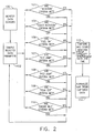
Figure 2 , the monitoring algorithm is described in more detail. The algorithm is initiated whenever an engine start sequence is begun. The first step, shown atblock 100, is to continuously monitor the output of theengine data sensors 20 andaircraft data sensors 21. Next, atblock 102, selected data parameters sensed by theengine data sensors 20 andaircraft data sensors 21 are continuously sampled. Typically, the data parameters are sampled at a high frequency, such as every 30-60 milliseconds, to collect a large volume of data points. Which data parameters are sampled can vary depending on a number of factors. By way of example only, the monitoring algorithm will be described herein with core speed, fuel flow, exhaust gas temperature (EGT) jump, compressor discharge pressure (PS3) jump, and peak exhaust gas temperature as the selected data parameters. However, it should be noted that the present invention is not limited to these particular data parameters and could be used with any suitable set of data parameters. - Next, each selected data parameter is evaluated to determine whether specific criteria have been met, as denoted at blocks 104-110. The purpose of this portion of the monitoring algorithm is to identify certain phases or times in the engine start sequence for monitoring engine starting system performance characteristics. In each instance, if the criteria are met at any of blocks 104-110, then the monitoring algorithm proceeds to block 112 where selected engine starting performance data and time when the criteria are met are captured and stored. That is, as each particular set of decision criteria is met, current engine and aircraft data are captured and stored with the corresponding data sampling time. If the criteria are not met at any of blocks 104-110, then the monitoring algorithm returns to block 102 so that the data parameters are continually sampled until the criteria for each of the blocks 104-110 have been met.
- Again by way of example only, the monitoring algorithm will be described herein by using seven engine start sequence phases wherein the selected data parameters are evaluated against a set of decision criteria. The data parameters are evaluated against "initiation" decision criteria at
block 104, "start rotation" decision criteria atblock 105, "fuel on" decision criteria atblock 106, "EGT jump" decision criteria atblock 107, "PS3 jump" decision criteria atblock 108, "peak EGT" decision criteria atblock 109, and "engine idle" decision criteria atblock 110. Thus, each decision block 104-110 captures data at a different phase or time of the engine start sequence. More specifically, the initiation decision criteria ofblock 104 are such that data are captured when the engine start sequence is first initiated. For example, the initiation decision criteria could be: 1) the starter valve is open. If this sole criterion is met (indicating that the engine start sequence has begun), then the pertinent engine and aircraft data at that specific time are captured and stored atblock 112. - The start rotation decision criteria of
block 105 are such that data are captured during an early phase of the engine start sequence where the engine core has achieved a relatively low rotation speed. For example, the start rotation decision criteria could be: 1) the starter valve is open and 2) the core speed is greater than or equal to 22% of the maximum core speed. If both of these criteria are met, then the pertinent engine and aircraft data at that specific time are captured and stored atblock 112. - The fuel on decision criteria of
block 106 relate to when the engine fuel flow has reached a predetermined level. For example, the fuel on decision criteria could be: 1) the starter valve is open, 2) the core speed is greater than or equal to 25% of the maximum core speed, and 3) the fuel flow is greater than or equal to 113.4 kg/hour (250 pounds/hour). If all of these criteria are met, then the pertinent engine and aircraft data at that specific time are captured and stored atblock 112. The EGT jump decision criteria ofblock 107 relate to whether the EGT is changing at a given rate during a certain stage of the engine start sequence. Similarly, the PS3 jump decision criteria ofblock 108 relate to whether the PS3 is changing at a given rate during a certain stage of the engine start sequence. For example, the EGT jump decision criteria could be: 1) the starter valve is open, 2) the core speed is less than or equal to 59% of the maximum core speed, 3) the fuel flow is greater than or equal to 113.4 kg/hour (250 pounds/hour), and 4) the EGT rate of change is greater than or equal to 10 °C/second. The PS3 jump decision criteria could be: 1) the starter valve is open, 2) the core speed is less than or equal to 59% of the maximum core speed, 3) the fuel flow is greater than or equal to 113.4 kg/hour (250 pounds/hour), and 4) the PS3 rate of change is greater than or equal to 34.5 kPa/hour (5 psi/second). In either case, if all of the criteria are met, then the pertinent engine and aircraft data at that specific time are captured and stored atblock 112. - The peak EGT decision criteria of
block 109 relate to when the EGT has peaked. This could be determined for any given sampling time, t, by comparing the EGT value with the EGT value of the two previous sampling times, t-1 and t-2. Thus, the two criteria would be 1) the EGT at sampling time t is less than the EGT at sampling time t-1 and 2) the EGT at sampling time t-1 is greater than the EGT at sampling time t-2. If both of these criteria are met, then it is assumed that the EGT peaked at sampling time t-1 and the pertinent engine and aircraft data at that specific time are captured and stored atblock 112. The engine idle decision criteria ofblock 110 relate to when the engine has reached idle, signifying the end of the engine start sequence. For example, the engine idle decision criteria could be: 1 the core speed is greater than or equal to 59% of the maximum core speed. If this sole criterion is met, then the pertinent engine starting performance data at that specific time are captured and stored atblock 112. - The data parameters that are captured at
block 112 are not necessarily the same as the data parameters sampled atblock 102, although one or more of the same data parameters can be used at both steps. The reason that the data parameter sets can differ is that the data are used for different reasons. The purpose for sampling data atblock 102 is to identify phases in the engine start sequence at which data are collected for trending, while atblock 112, the goal is to capture the data to be used in a diagnostic trending analysis for monitoring engine starting system performance. Thus, the data parameters captured atblock 112 will be related to engine starting system performance. Examples of preferred data parameters captured atblock 112 include engine data such as fan speed, core speed, EGT, fuel flow and starter air pressure, and aircraft data such as altitude, ambient pressure and ambient temperature. It should be pointed out that the present invention is not limited to these data parameters, which are given only by way of example. - The data parameters captured at
block 112 are not necessarily the same for each phase of the engine start sequence. Generally the data parameters collected at each phase will depend on the reason for capturing data at that particular phase. For example, the purpose for capturing data at the initiation of the engine start sequence is to establish a time baseline for the subsequent trending analysis. Thus, one possible approach is to capture all the selected engine and aircraft data parameters in response to the initiation criteria being met inblock 104. Then, various subsets of these data parameters (particularly the engine-related data) can be captured in response to the specific decision criteria for blocks 105-110 being met. - The captured data for each data parameter is then normalized and trended against reference data, as indicated at
block 114, to determine the engine starting system performance. The captured data is first normalized so that the data can be compared to the reference data that may have been collected at different ambient conditions (e.g., different altitudes, temperatures, auxiliary air pressures, etc.). The normalized data is compared to similar data from prior start sequences. Deviation of the current normalized data from the historical values indicates degradation in engine starting system effectiveness.
Claims (9)
- A method of monitoring engine starting system performance in a gas turbine engine (12), said method comprising:using a plurality of sensors (20,21) to sense data related to the operation and performance of said gas turbine engine (12);initiating an engine start sequence for said gas turbine engine (12);continuously sampling selected data parameters from said sensed data during an engine start sequence; characterized by:evaluating said data parameters to determine whether specific criteria have been met;capturing selected engine starting system performance data when said specific criteria are met;normalizing said captured engine starting system performance data; andtrending said normalized engine starting system performance data by comparing it to a parametric baseline for said gas turbine engine (12).
- The method of claim 1 further comprising capturing data sampling times when capturing said selected engine starting system performance data.
- The method of claim 1 wherein said criteria correspond to predetermined phases of an engine start sequence.
- The method of claim 1 wherein said gas turbine engine (12) includes a starter valve and said criteria include said starter valve being open.
- The method of claim 1 wherein said data parameters include one or more of core speed, fuel flow, exhaust gas temperature and compressor discharge pressure.
- The method of claim 1 wherein one of said sets of criteria pertains to an engine start sequence being initiated.
- A system (10) for monitoring engine starting system performance in a gas turbine engine (12), said system (10) comprising:a plurality of sensors (20,21) for sensing data related to the operation and performance of said gas turbine engine (12);means (16,18,26) for continuously sampling selected data parameters from said data sensors (20,21) during an engine start sequence; characterized by:means (16,18,26) for evaluating said data parameters to determine whether specific criteria have been met;means (16,18,26) for capturing selected engine starting system performance data when said specific criteria are met;means for normalizing said captured engine starting system performance data; andmeans for trending said normalized engine starting system performance data by comparing it to a parametric baseline for said gas turbine engine (12).
- The system (10) of claim 7 further comprising means (16,18,26) for capturing data sampling times when capturing said selected engine starting system performance data.
- A computer-readable medium containing instructions for controlling a computer-based system (10) having a plurality of sensors (20,21) for sensing predetermined parameter values related to the operation and performance of a gas turbine engine (12) to perform the method of claim 1.
Applications Claiming Priority (2)
| Application Number | Priority Date | Filing Date | Title |
|---|---|---|---|
| US861336 | 2001-05-18 | ||
| US09/861,336 US6470258B1 (en) | 2001-05-18 | 2001-05-18 | System and method for monitoring engine starting systems |
Publications (3)
| Publication Number | Publication Date |
|---|---|
| EP1260690A2 EP1260690A2 (en) | 2002-11-27 |
| EP1260690A3 EP1260690A3 (en) | 2004-12-08 |
| EP1260690B1 true EP1260690B1 (en) | 2009-11-11 |
Family
ID=25335523
Family Applications (1)
| Application Number | Title | Priority Date | Filing Date |
|---|---|---|---|
| EP02253389A Expired - Lifetime EP1260690B1 (en) | 2001-05-18 | 2002-05-15 | System and method for monitoring gas turbine engine starting systems |
Country Status (4)
| Country | Link |
|---|---|
| US (1) | US6470258B1 (en) |
| EP (1) | EP1260690B1 (en) |
| JP (1) | JP4171610B2 (en) |
| DE (1) | DE60234287D1 (en) |
Families Citing this family (40)
| Publication number | Priority date | Publication date | Assignee | Title |
|---|---|---|---|---|
| US6498978B2 (en) * | 2001-05-18 | 2002-12-24 | General Electric Company | System and method for monitoring thermal state to normalize engine trending data |
| US6942451B1 (en) | 2003-06-03 | 2005-09-13 | Hamilton Sundstrand Corporation | Damping system for an expendable gas turbine engine |
| US7194866B1 (en) | 2003-06-20 | 2007-03-27 | Hamilton Sundstrand Corporation | Static structure for an expendable gas turbine engine |
| US6943699B2 (en) * | 2003-07-23 | 2005-09-13 | Harris Corporation | Wireless engine monitoring system |
| US8438858B1 (en) | 2003-08-20 | 2013-05-14 | Hamilton Sundstrand Corporation | Rotational system for an expendable gas turbine engine |
| US7072797B2 (en) | 2003-08-29 | 2006-07-04 | Honeywell International, Inc. | Trending system and method using monotonic regression |
| US7231180B2 (en) * | 2004-03-24 | 2007-06-12 | Honeywell International, Inc. | Aircraft engine sensor network using wireless sensor communication modules |
| US7216489B2 (en) * | 2004-05-26 | 2007-05-15 | Honeywell International, Inc. | System and method for lightoff detection in turbine engines |
| US7140240B2 (en) * | 2004-06-21 | 2006-11-28 | Hamilton Sundstrand | Electric engine start system with inspection mode |
| US7254491B2 (en) * | 2004-06-28 | 2007-08-07 | Honeywell International, Inc. | Clustering system and method for blade erosion detection |
| US7506517B2 (en) * | 2004-11-23 | 2009-03-24 | Honeywell International, Inc. | System and method for turbine engine startup profile characterization |
| US20060129301A1 (en) * | 2004-12-14 | 2006-06-15 | General Electric Company | Method and apparatus for assessing gas turbine acceleration capability |
| US7693643B2 (en) * | 2005-02-14 | 2010-04-06 | Honeywell International Inc. | Fault detection system and method for turbine engine fuel systems |
| US7191084B2 (en) * | 2005-04-20 | 2007-03-13 | General Electric Company | Method and apparatus for gas turbine engine ignition systems |
| US7577549B2 (en) * | 2005-07-18 | 2009-08-18 | General Electric Company | System and method for trending exhaust gas temperature in a turbine engine |
| US7369932B2 (en) * | 2006-05-04 | 2008-05-06 | Honeywell International, Inc. | System and method for turbine engine fault detection using discrete event system modeling |
| JP5611942B2 (en) * | 2008-06-26 | 2014-10-22 | ガンブロ・ルンディア・エービーGambro Lundia Ab | Method and device for processing time-dependent measurement signals |
| US9121769B2 (en) * | 2008-08-20 | 2015-09-01 | United Technologies Corporation | Sensor and antenna arrangement |
| US8467949B2 (en) * | 2009-05-29 | 2013-06-18 | Honeywell International Inc. | Methods and systems for turbine line replaceable unit fault detection and isolation during engine startup |
| US8370045B2 (en) * | 2009-08-14 | 2013-02-05 | Lockheed Martin Corporation | Starter control valve failure prediction machine to predict and trend starter control valve failures in gas turbine engines using a starter control valve health prognostic, program product and related methods |
| US9053468B2 (en) * | 2011-04-07 | 2015-06-09 | General Electric Company | Methods and systems for monitoring operation of equipment |
| US20130212210A1 (en) * | 2012-02-10 | 2013-08-15 | General Electric Company | Rule engine manager in memory data transfers |
| FR2998003B1 (en) * | 2012-11-12 | 2014-11-07 | Snecma | METHOD FOR MONITORING AN IGNITION SEQUENCE OF A TURBOMACHINE ENGINE |
| US10309317B2 (en) * | 2013-06-21 | 2019-06-04 | Hamilton Sundstrand Corporation | Air turbine starter pressure monitor system |
| GB201313140D0 (en) * | 2013-07-23 | 2013-09-04 | Rolls Royce Engine Control Systems Ltd | System for performing staging control of a multi-stage combustor |
| CN104343476B (en) * | 2013-07-24 | 2016-06-08 | 中国国际航空股份有限公司 | Airplane auxiliary power unit turbine efficiency monitoring method and apparatus |
| CN105593118B (en) * | 2013-10-07 | 2019-04-16 | 通用电气航空系统有限公司 | Method for being diagnosed to be Auxiliary Power Unit failure |
| FR3018546B1 (en) * | 2014-03-13 | 2022-01-21 | Snecma | METHOD FOR MONITORING THE CONDITION OF AN ENGINE BY MONITORING THE EXHAUST GAS |
| US10553120B2 (en) | 2014-09-15 | 2020-02-04 | L3 Technologies, Inc. | Fail safe aircraft monitoring and tracking |
| US9952612B2 (en) | 2015-03-03 | 2018-04-24 | Caterpillar Inc. | Power system having zone-based load sharing |
| WO2017055975A1 (en) | 2015-09-30 | 2017-04-06 | Bombardier Inc. | Method of and system for presenting an operating status of an aircraft engine |
| US10587307B2 (en) | 2016-06-20 | 2020-03-10 | Ge Aviation Systems, Llc | Transmission of power and communication of signals over fuel and hydraulic lines in a vehicle |
| US10454525B2 (en) | 2016-06-20 | 2019-10-22 | Ge Aviation Systems Llc | Communication of signals over fuel lines in a vehicle |
| US10598095B2 (en) | 2016-10-11 | 2020-03-24 | Unison Industries, Llc | Integrated starter for aerial vehicle |
| US10266278B2 (en) | 2016-10-11 | 2019-04-23 | Unison Industries, Llc | Starter issue detection |
| US20180209295A1 (en) * | 2016-10-11 | 2018-07-26 | General Electric Company | Starter controller |
| US11225915B2 (en) | 2017-11-16 | 2022-01-18 | General Electric Company | Engine core speed reducing method and system |
| CN113291488B (en) * | 2021-04-30 | 2022-01-04 | 浙江长龙航空有限公司 | Method and device for monitoring performance of integral drive generator |
| US12061937B2 (en) * | 2022-06-22 | 2024-08-13 | Allegro Microsystems, Llc | Methods and apparatus for sensor data consistency |
| CN115577575B (en) * | 2022-12-08 | 2023-03-14 | 太仓点石航空动力有限公司 | Compressor performance degradation identification method and system based on pressure ratio index |
Family Cites Families (9)
| Publication number | Priority date | Publication date | Assignee | Title |
|---|---|---|---|---|
| US4215412A (en) * | 1978-07-13 | 1980-07-29 | The Boeing Company | Real time performance monitoring of gas turbine engines |
| GB8729962D0 (en) * | 1987-12-23 | 1988-02-03 | Smiths Industries Plc | Engine monitoring |
| US5107674A (en) * | 1990-03-30 | 1992-04-28 | General Electric Company | Control for a gas turbine engine |
| US5583420A (en) * | 1993-10-01 | 1996-12-10 | Lucas Aerospace Power Equipment Corporation | Microprocessor controller for starter/generator |
| GB2291199A (en) * | 1994-07-09 | 1996-01-17 | Rolls Royce Plc | Steady state sensor |
| US5748500A (en) * | 1995-11-14 | 1998-05-05 | Electric Power Research Institute, Inc. | System to assess the starting performance of a turbine |
| US5845483A (en) * | 1996-04-10 | 1998-12-08 | General Electric Company | Windmill engine starting system with fluid driven motor and pump |
| US6466858B1 (en) * | 2000-11-02 | 2002-10-15 | General Electric Company | Methods and apparatus for monitoring gas turbine engine operation |
| US6498978B2 (en) * | 2001-05-18 | 2002-12-24 | General Electric Company | System and method for monitoring thermal state to normalize engine trending data |
-
2001
- 2001-05-18 US US09/861,336 patent/US6470258B1/en not_active Expired - Lifetime
-
2002
- 2002-05-15 DE DE60234287T patent/DE60234287D1/en not_active Expired - Lifetime
- 2002-05-15 EP EP02253389A patent/EP1260690B1/en not_active Expired - Lifetime
- 2002-05-16 JP JP2002140856A patent/JP4171610B2/en not_active Expired - Fee Related
Also Published As
| Publication number | Publication date |
|---|---|
| EP1260690A3 (en) | 2004-12-08 |
| JP2003090232A (en) | 2003-03-28 |
| DE60234287D1 (en) | 2009-12-24 |
| US6470258B1 (en) | 2002-10-22 |
| EP1260690A2 (en) | 2002-11-27 |
| JP4171610B2 (en) | 2008-10-22 |
Similar Documents
| Publication | Publication Date | Title |
|---|---|---|
| EP1260690B1 (en) | System and method for monitoring gas turbine engine starting systems | |
| EP1258618B1 (en) | System and method for monitoring engine performance in a gas turbine engine | |
| US7197430B2 (en) | Method and apparatus for determining engine part life usage | |
| US6628995B1 (en) | Method and system for variable flight data collection | |
| Eustace et al. | Fault signatures obtained from fault implant tests on an F404 engine | |
| EP1400942B1 (en) | Method and system for uploading and downloading engine control data | |
| EP3705726A1 (en) | Application of machine learning to process high-frequency sensor signals of a turbine engine | |
| US20070250245A1 (en) | Method and apparatus for operating a gas turbine engine | |
| JP2010209916A (en) | Wireless engine monitoring system | |
| EP3992929A1 (en) | System and method for transmission of engine fault data | |
| EP4276296A1 (en) | Monitoring engine operation | |
| EP3712737B1 (en) | Signal response monitoring for turbine engines | |
| US11719170B2 (en) | Method for monitoring engine health of aircraft | |
| EP4318143A1 (en) | System and method for addressing redundant sensor mismatch in an engine control system | |
| EP4332708A1 (en) | Engine control system and method with artificial intelligence sensor training | |
| EP4033420A1 (en) | System and method for tracking engine and aircraft component data | |
| US20220269841A1 (en) | System and method for monitoring and diagnosis of engine health using a snapshot-ceod based approach | |
| US20230230424A1 (en) | Method and system for data transmission from an aircraft engine | |
| Xinlei et al. | Civil Aircraft Engine Start System Health Monitoring Method Based on QAR Data | |
| Eustace et al. | Fault signatures obtained from fault implant tests on an F404 engine |
Legal Events
| Date | Code | Title | Description |
|---|---|---|---|
| PUAI | Public reference made under article 153(3) epc to a published international application that has entered the european phase |
Free format text: ORIGINAL CODE: 0009012 |
|
| AK | Designated contracting states |
Kind code of ref document: A2 Designated state(s): AT BE CH CY DE DK ES FI FR GB GR IE IT LI LU MC NL PT SE TR |
|
| AX | Request for extension of the european patent |
Free format text: AL;LT;LV;MK;RO;SI |
|
| PUAL | Search report despatched |
Free format text: ORIGINAL CODE: 0009013 |
|
| AK | Designated contracting states |
Kind code of ref document: A3 Designated state(s): AT BE CH CY DE DK ES FI FR GB GR IE IT LI LU MC NL PT SE TR |
|
| AX | Request for extension of the european patent |
Extension state: AL LT LV MK RO SI |
|
| RIC1 | Information provided on ipc code assigned before grant |
Ipc: 7F 01D 19/00 B Ipc: 7F 02C 9/00 B Ipc: 7F 02C 7/26 A |
|
| 17P | Request for examination filed |
Effective date: 20050608 |
|
| AKX | Designation fees paid |
Designated state(s): DE FR GB IT |
|
| 17Q | First examination report despatched |
Effective date: 20051107 |
|
| GRAP | Despatch of communication of intention to grant a patent |
Free format text: ORIGINAL CODE: EPIDOSNIGR1 |
|
| GRAS | Grant fee paid |
Free format text: ORIGINAL CODE: EPIDOSNIGR3 |
|
| GRAA | (expected) grant |
Free format text: ORIGINAL CODE: 0009210 |
|
| AK | Designated contracting states |
Kind code of ref document: B1 Designated state(s): DE FR GB IT |
|
| REG | Reference to a national code |
Ref country code: GB Ref legal event code: FG4D |
|
| REF | Corresponds to: |
Ref document number: 60234287 Country of ref document: DE Date of ref document: 20091224 Kind code of ref document: P |
|
| PLBE | No opposition filed within time limit |
Free format text: ORIGINAL CODE: 0009261 |
|
| STAA | Information on the status of an ep patent application or granted ep patent |
Free format text: STATUS: NO OPPOSITION FILED WITHIN TIME LIMIT |
|
| 26N | No opposition filed |
Effective date: 20100812 |
|
| PGFP | Annual fee paid to national office [announced via postgrant information from national office to epo] |
Ref country code: GB Payment date: 20140527 Year of fee payment: 13 |
|
| PGFP | Annual fee paid to national office [announced via postgrant information from national office to epo] |
Ref country code: FR Payment date: 20140519 Year of fee payment: 13 Ref country code: DE Payment date: 20140529 Year of fee payment: 13 Ref country code: IT Payment date: 20140526 Year of fee payment: 13 |
|
| REG | Reference to a national code |
Ref country code: DE Ref legal event code: R119 Ref document number: 60234287 Country of ref document: DE |
|
| GBPC | Gb: european patent ceased through non-payment of renewal fee |
Effective date: 20150515 |
|
| PG25 | Lapsed in a contracting state [announced via postgrant information from national office to epo] |
Ref country code: IT Free format text: LAPSE BECAUSE OF NON-PAYMENT OF DUE FEES Effective date: 20150515 |
|
| REG | Reference to a national code |
Ref country code: FR Ref legal event code: ST Effective date: 20160129 |
|
| PG25 | Lapsed in a contracting state [announced via postgrant information from national office to epo] |
Ref country code: GB Free format text: LAPSE BECAUSE OF NON-PAYMENT OF DUE FEES Effective date: 20150515 Ref country code: DE Free format text: LAPSE BECAUSE OF NON-PAYMENT OF DUE FEES Effective date: 20151201 |
|
| PG25 | Lapsed in a contracting state [announced via postgrant information from national office to epo] |
Ref country code: FR Free format text: LAPSE BECAUSE OF NON-PAYMENT OF DUE FEES Effective date: 20150601 |