EP1258618B1 - System and method for monitoring engine performance in a gas turbine engine - Google Patents
System and method for monitoring engine performance in a gas turbine engine Download PDFInfo
- Publication number
- EP1258618B1 EP1258618B1 EP02253390A EP02253390A EP1258618B1 EP 1258618 B1 EP1258618 B1 EP 1258618B1 EP 02253390 A EP02253390 A EP 02253390A EP 02253390 A EP02253390 A EP 02253390A EP 1258618 B1 EP1258618 B1 EP 1258618B1
- Authority
- EP
- European Patent Office
- Prior art keywords
- engine
- gas turbine
- data parameters
- data
- turbine engine
- Prior art date
- Legal status (The legal status is an assumption and is not a legal conclusion. Google has not performed a legal analysis and makes no representation as to the accuracy of the status listed.)
- Expired - Lifetime
Links
- 238000012544 monitoring process Methods 0.000 title claims description 28
- 238000000034 method Methods 0.000 title claims description 14
- 238000011156 evaluation Methods 0.000 claims description 17
- 239000000446 fuel Substances 0.000 claims description 10
- 239000007858 starting material Substances 0.000 claims description 6
- 238000005070 sampling Methods 0.000 claims description 5
- 230000000977 initiatory effect Effects 0.000 claims 1
- 239000007789 gas Substances 0.000 description 18
- 238000012423 maintenance Methods 0.000 description 6
- 238000012545 processing Methods 0.000 description 4
- 238000013480 data collection Methods 0.000 description 2
- 238000013500 data storage Methods 0.000 description 2
- 238000013154 diagnostic monitoring Methods 0.000 description 2
- 238000010586 diagram Methods 0.000 description 2
- 239000000284 extract Substances 0.000 description 2
- 230000010006 flight Effects 0.000 description 2
- 101100001915 Drosophila melanogaster Hmu gene Proteins 0.000 description 1
- 101100017564 Haloquadratum walsbyi (strain DSM 16790 / HBSQ001) hmu gene Proteins 0.000 description 1
- 230000015556 catabolic process Effects 0.000 description 1
- 239000000567 combustion gas Substances 0.000 description 1
- 238000004891 communication Methods 0.000 description 1
- 238000006731 degradation reaction Methods 0.000 description 1
- 230000000694 effects Effects 0.000 description 1
- 238000005259 measurement Methods 0.000 description 1
- 239000000203 mixture Substances 0.000 description 1
- 238000010606 normalization Methods 0.000 description 1
- 230000003287 optical effect Effects 0.000 description 1
- 238000012216 screening Methods 0.000 description 1
- 238000012546 transfer Methods 0.000 description 1
Images

Classifications
-
- F—MECHANICAL ENGINEERING; LIGHTING; HEATING; WEAPONS; BLASTING
- F02—COMBUSTION ENGINES; HOT-GAS OR COMBUSTION-PRODUCT ENGINE PLANTS
- F02C—GAS-TURBINE PLANTS; AIR INTAKES FOR JET-PROPULSION PLANTS; CONTROLLING FUEL SUPPLY IN AIR-BREATHING JET-PROPULSION PLANTS
- F02C9/00—Controlling gas-turbine plants; Controlling fuel supply in air- breathing jet-propulsion plants
- F02C9/26—Control of fuel supply
- F02C9/28—Regulating systems responsive to plant or ambient parameters, e.g. temperature, pressure, rotor speed
-
- F—MECHANICAL ENGINEERING; LIGHTING; HEATING; WEAPONS; BLASTING
- F05—INDEXING SCHEMES RELATING TO ENGINES OR PUMPS IN VARIOUS SUBCLASSES OF CLASSES F01-F04
- F05D—INDEXING SCHEME FOR ASPECTS RELATING TO NON-POSITIVE-DISPLACEMENT MACHINES OR ENGINES, GAS-TURBINES OR JET-PROPULSION PLANTS
- F05D2220/00—Application
- F05D2220/50—Application for auxiliary power units (APU's)
Definitions
- This invention relates generally to gas turbine engines and more particularly to monitoring the thermal state in such engines.
- Gas turbine engines are used for a wide variety of aeronautical, marine and industrial applications.
- a gas turbine engine includes a compressor that provides pressurized air to a combustor, wherein the air is mixed with fuel and the mixture is ignited for generating hot combustion gases. These gases flow downstream to a turbine section that extracts energy therefrom to drive the compressor and provide useful work.
- gas turbine engines are routinely subject to various maintenance procedures as part of their normal operation.
- monitoring systems are often employed to provide diagnostic monitoring of the gas turbine engine. These systems commonly include performance monitoring equipment that collects relevant trend and fault data used for diagnostic trending.
- process data such as exhaust gas temperature, fuel flow, rotor speed and the like
- process data that are indicative of overall engine performance and/or condition are compared to a parametric baseline for the gas turbine engine. Any divergence of the raw trend data from the parametric baseline may be indicative of a present or future condition that requires maintenance.
- modern aircraft currently operated by commercial airlines typically employ an onboard data acquisition system for collecting digital flight data to use in diagnostic monitoring.
- a number of sensors distributed throughout the aircraft and engines provide data signals representative of the performance of the aircraft and its engines.
- Such data can be recorded onboard and accessed later by ground maintenance personnel or, alternatively, can be remotely transmitted to ground locations during flight operations for real-time processing.
- Engine condition monitoring techniques typically use a screening process to identify various phases of operation and then extract specific data during the flight phases of interest.
- flight phases such as take off, climb and steady cruise, because these are the phases during which engine anomalies are most likely to be detected.
- Data collected during the takeoff phase can be strongly influenced by the engine's thermal state at engine start-up. For example, bearing and rotor clearances are generally more open during a cold rotor start (e.g., the first start of the day) than during a hot start (e.g., a start after a recently concluded flight). This means that rubbing and rotor bow are more likely to occur during hot starts.
- the present invention provides a method and system for monitoring engine performance in a gas turbine engine in which a plurality of sensors are used to sense data related to the operation and performance of the gas turbine engine. Selected data parameters from the sensed data are continuously sampled prior to completion of an engine start sequence. The selected data parameters are then evaluated to determine whether specific criteria have been met, and evaluation data parameters are captured whenever the criteria are met. The evaluation data parameters are used to normalize engine performance data parameters to a particular thermal state of the engine. The normalized engine performance data parameters are then trended by comparing it to a parametric baseline for the gas turbine engine.
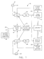
- Figure 1 shows a block diagram of system 10 for monitoring the performance of gas turbine engines 12, 13 mounted on an aircraft 14.
- two engines 12, 13 are shown in Figure 1 , it should be noted that the aircraft 14 could have additional engines mounted thereon.
- data collection for such additional engines would be accomplished in a manner identical to that for engines 12, 13. Therefore, only engines 12, 13 and the associated equipment will be described herein.
- the system 10 is described in connection with an aircraft only by way of example. In addition to aeronautical applications, the present invention is applicable to other applications of gas turbine engines, including marine and industrial applications.
- the system 10 includes an electronic control unit (ECU) 16, such as a full authority digital engine control (FADEC) although other controllers can be used, associated with each engine 12, 13 and an onboard aircraft data box 18.
- ECU electronice control unit
- FADEC full authority digital engine control
- Conventional engine data sensors 20 and aircraft data sensors 21 are provided to sense selected data parameters related to the operation and performance of the engines 12, 13 and/or the aircraft 14.
- the engine data sensors 20 and aircraft data sensors 21 can comprise any group of sensors that monitor data parameters of interest.
- engine parameters would typically include exhaust gas temperature, oil temperature, component temperatures such as high pressure turbine shroud temperature, engine fuel flow, core speed, compressor discharge pressure, turbine exhaust pressure, fan speed, and the like.
- Each ECU 16 receives signals from the corresponding engine data sensors 20 and the aircraft data sensors 21 as is known in the art. Each ECU 16 also receives a thrust request signal from a corresponding throttle 22 controlled by the aircraft's pilot. In response to these inputs, the ECUs 16 generate command signals to operate engine actuators, such as hydromechanical units (HMU) 24 that meter the flow of fuel to the respective engine 12, 13. The HMUs 24 are units that are well known to those skilled in the art. Each ECU 16 also outputs data signals to the aircraft data box 18.
- the aircraft data box 18, which can be any conventional device such as a flight data recorder, quick access recorder, or any other type of in-flight data storage device, has a relatively large data storage capacity for storing the data signals.
- the aircraft data box 18 could also contain processing capability to analyze data in-flight and only send the necessary maintenance messages to an aircraft centralized maintenance computer (not shown).
- the aircraft data box 18 also receives signals from the aircraft data sensors 21.
- each engine 12, 13 includes an engine starting system having an engine turbine starter that is mounted on the engine's gearbox.
- auxiliary air is delivered to the starter, which causes the engine core to rotate via the gearbox.
- the ECUs 16 schedule fuel delivery and variable geometry adjustments to complete the engine start sequence and bring the respective engine 12, 13 to idle operating condition.
- the source of auxiliary air is an auxiliary power unit (APU) which is usually located in the tail of an aircraft 14, a ground cart, or cross bleed from another engine.
- APU auxiliary power unit
- the system 10 includes an algorithm that processes the data signals for monitoring engine performance characteristics.
- the monitoring algorithm can be implemented in a number of ways.
- the monitoring algorithm could be implemented on the ECUs 16 wherein the data signals are processed as they are received by the ECUs 16.
- the monitoring algorithm could be implemented on the aircraft data box 18. In this case, the data signals would be processed after being transferred to the aircraft data box 18.
- a ground station computer 26 such as personal or workstation computer. The data signals stored in the aircraft data box 18 during a flight are downloaded to the ground station computer for processing.
- This transfer can be accomplished after the flight via any sort of link 28 including use of a removable computer-readable medium, such as a floppy disk, CD-ROM or other optical medium, magnetic tape or the like, or a wireless communication link. It is also possible to remotely transmit the data signals directly to the ground station computer 26 during flight operations for real-time processing.
- the monitoring algorithm can be stored on the unit (be it the ECU, aircraft data box or ground station computer) and accessed from there, or alternatively, it could be accessed from a removable computer-readable medium inserted into the appropriate drive of the unit.
- the monitoring. algorithm could also be accessed via the Internet or another computer network.
- computer-readable medium refers generally to any medium from which stored data can be read by a computer or similar unit. This includes not only removable media such as the aforementioned floppy disk and CD-ROM, but also non-removable media such as a hard disk or integrated circuit memory device in each ECU 16, aircraft data box 18 or ground station computer 26.
- the algorithm is initiated whenever an engine start sequence is begun.
- the first step shown at block 100, is to continuously monitor the output of the engine data sensors 20 and aircraft data sensors 21.
- selected data parameters sensed by the data sensors 20 and aircraft data sensors 21 are continuously sampled.
- the data parameters are sampled at a high frequency, such as every 15-60 milliseconds, to collect a large volume of data points.
- Which data parameters are sampled can vary depending on a number of factors.
- the monitoring algorithm will be described herein with core speed and fuel flow as the selected data parameters.
- the present invention is not limited to these particular data parameters and could be used with any suitable set of data parameters.
- each data sample is evaluated to determine whether specific criteria have been met, as denoted at blocks 104 and 106.
- the purpose of this portion of the monitoring algorithm is to identify, for each engine 12, 13, the specific time prior to completion of the engine start sequence at which the engine thermal state is to be determined. In each instance, if the criteria are met at either of blocks 104, 106, then the monitoring algorithm proceeds to block 108 where selected engine and aircraft data and time when the criteria are met are captured and stored. That is, as each particular set of decision criteria is met, current engine and aircraft data, referred to hereinafter as "evaluation data parameters," are captured and stored with the corresponding data sampling time. If the criteria are not met at either of blocks 104, 106, then the monitoring algorithm returns to block 102 so that the data parameters are continually sampled until the criteria for each block 104, 106 have been met.
- the monitoring algorithm will be described herein by using two categories for which the data samples are evaluated against a set of decision criteria.
- the data parameters are evaluated against decision criteria for the first engine 12 at block 104, and against decision criteria for the second engine 13 at block 106.
- the decision criteria of block 104 are such that evaluation data parameters are captured before the engine start sequence for the first engine 12 is completed.
- the decision criteria could be: 1) the starter valve is open, 2) fuel flow is off, and 3) the core speed is greater than or equal to 25% of the maximum core speed. If all of these criteria are met (indicating that the engine start sequence has begun but is not yet completed), then the pertinent engine and aircraft data at that specific time are captured and stored at block 108.
- the decision criteria of block 106 are such that evaluation data parameters are captured before the engine start sequence for the second engine 13 is completed.
- the decision criteria could be: 1) the starter valve is open, 2) fuel flow is off, and 3) the core speed is greater than or equal to 25% of the maximum core speed. If all of these criteria are met (indicating that the engine start sequence has begun but is not yet completed), then the pertinent engine and aircraft data at that specific time are captured and stored at block 108.
- the evaluation data parameters that are captured at block 108 are not necessarily the same as the data parameters sampled at block 102, although one or more of the same data parameters can be used at both steps.
- the reason that the data parameter sets can differ is that the data are used for different reasons.
- the purpose for sampling data at block 102 is to identify when to collect evaluation for subsequent use.
- the goal is to capture evaluation data parameters that will be used for assessing the engine thermal state and normalizing engine performance data.
- examples of preferred evaluation data parameters captured at block 108 include oil temperature, high pressure turbine (HPT) shroud temperature, ambient temperature, exhaust gas temperature (EGT) and core speed. It should be pointed out that the present invention is not limited to these data parameters, which are given only by way of example.
- the algorithm uses the captured data to make an assessment of each engine's thermal state prior to completion of the engine start sequence. This is accomplished by applying a set of logic to the evaluation data parameters. For example, the oil temperature being equal to the ambient temperature indicates that the engine has been shut down for a long time. It is thus determined that the engine had a cold thermal state at start-up. Similarly, the high pressure turbine shroud temperature being equal to ambient temperature indicates that the engine has been shut down for a long period of time. If the oil and high pressure turbine shroud temperatures are greater than ambient, the time since the last engine shut-down can be determined by models of the temperature decay characteristics. A similar strategy can be applied to EGT measurements.
- engine performance data parameters sensed by the data sensors 20 and aircraft data sensors 21 are continuously sampled. These data parameters are also typically sampled at a high frequency, such as every 15-60 milliseconds, to collect a large volume of data points.
- the data parameters sampled at block 112 relate to engine performance and are ultimately used in a diagnostic trending analysis for monitoring engine performance.
- data parameters sampled at block 112 can include data such as fan speed, core speed, EGT, engine fuel flow, altitude, ambient pressure, total temperature, Mach number, compressor inlet and exit temperature, compressor exit pressure, engine pressure ratio, oil temperature, high pressure turbine shroud temperature, active clearance control valve positions, engine customer bleed settings, and all parameters calculated within the ECUs, although this step is not limited to these particular data parameters.
- each data sample collected at block 112 is normalized to a particular thermal state, as shown at block 114.
- the normalization is based on the thermal state assessment for each engine 12, 13 made at block 110.
- the engine performance data parameters are normalized for the corresponding thermal state prior to start-up so that the parameters can be compared to reference data that was collected during a flight in which the engine had a different thermal state prior to start-up. This will thus eliminate the affect that different bearing, rotor clearances, or similar effects during start-up will have on the subsequently collected engine performance data parameters.
- the normalized engine performance data parameters is then trended against reference data, as indicated at block 116, to monitor engine performance.
- the normalized data for each engine 12, 13 are compared to a parametric baseline derived from similar data obtained from prior flights. Because the engine performance data parameters have been normalized, it does not matter if the historical data was obtained from prior flights in which the engines had a different thermal state at start-up. Deviation of the current normalized data from the historical values may be an indication of potential engine performance degradation.
Landscapes
- Engineering & Computer Science (AREA)
- Chemical & Material Sciences (AREA)
- Combustion & Propulsion (AREA)
- Mechanical Engineering (AREA)
- General Engineering & Computer Science (AREA)
- Combined Controls Of Internal Combustion Engines (AREA)
- Control Of Turbines (AREA)
- Testing Of Engines (AREA)
Description
- This invention relates generally to gas turbine engines and more particularly to monitoring the thermal state in such engines.
- Gas turbine engines are used for a wide variety of aeronautical, marine and industrial applications. Generally, a gas turbine engine includes a compressor that provides pressurized air to a combustor, wherein the air is mixed with fuel and the mixture is ignited for generating hot combustion gases. These gases flow downstream to a turbine section that extracts energy therefrom to drive the compressor and provide useful work. In many applications, gas turbine engines are routinely subject to various maintenance procedures as part of their normal operation. To aid in the provision of such maintenance services, monitoring systems are often employed to provide diagnostic monitoring of the gas turbine engine. These systems commonly include performance monitoring equipment that collects relevant trend and fault data used for diagnostic trending. In diagnostic trend analysis, certain process data (such as exhaust gas temperature, fuel flow, rotor speed and the like) that are indicative of overall engine performance and/or condition are compared to a parametric baseline for the gas turbine engine. Any divergence of the raw trend data from the parametric baseline may be indicative of a present or future condition that requires maintenance.
- For example, modern aircraft currently operated by commercial airlines typically employ an onboard data acquisition system for collecting digital flight data to use in diagnostic monitoring. In such systems, a number of sensors distributed throughout the aircraft and engines provide data signals representative of the performance of the aircraft and its engines. Such data can be recorded onboard and accessed later by ground maintenance personnel or, alternatively, can be remotely transmitted to ground locations during flight operations for real-time processing.
- Engine condition monitoring techniques typically use a screening process to identify various phases of operation and then extract specific data during the flight phases of interest. Currently, data collection is conducted during flight phases such as take off, climb and steady cruise, because these are the phases during which engine anomalies are most likely to be detected. Data collected during the takeoff phase can be strongly influenced by the engine's thermal state at engine start-up. For example, bearing and rotor clearances are generally more open during a cold rotor start (e.g., the first start of the day) than during a hot start (e.g., a start after a recently concluded flight). This means that rubbing and rotor bow are more likely to occur during hot starts.
-
US 5,748,500 describes a system to assess the starting performance of a turbine. -
US 4,215,412 describes real time performance monitoring of gas turbine engines. - Accordingly, it is desirable to be able to monitor engine thermal state characteristics in gas turbine engines prior to engine start-up for the purpose of normalizing general engine performance characteristics.
- The above-mentioned need is met by the present invention, which provides a method and system for monitoring engine performance in a gas turbine engine in which a plurality of sensors are used to sense data related to the operation and performance of the gas turbine engine. Selected data parameters from the sensed data are continuously sampled prior to completion of an engine start sequence. The selected data parameters are then evaluated to determine whether specific criteria have been met, and evaluation data parameters are captured whenever the criteria are met. The evaluation data parameters are used to normalize engine performance data parameters to a particular thermal state of the engine. The normalized engine performance data parameters are then trended by comparing it to a parametric baseline for the gas turbine engine.
- The present invention and its advantages over the prior art will become apparent upon reading the following detailed description and the appended claims with reference to the accompanying drawings, in which:
-
Figure 1 is a schematic diagram of a system for monitoring engine performance in gas turbine engines, including an algorithm for monitoring engine thermal state characteristics prior to engine start-up. -
Figure 2 is a flow chart illustrating an algorithm for monitoring engine thermal state characteristics prior to engine start-up. - Referring to the drawings wherein identical reference numerals denote the same elements throughout the various views,
Figure 1 shows a block diagram ofsystem 10 for monitoring the performance ofgas turbine engines aircraft 14. Although twoengines Figure 1 , it should be noted that theaircraft 14 could have additional engines mounted thereon. As will be apparent from the following description, data collection for such additional engines would be accomplished in a manner identical to that forengines engines system 10 is described in connection with an aircraft only by way of example. In addition to aeronautical applications, the present invention is applicable to other applications of gas turbine engines, including marine and industrial applications. - The
system 10 includes an electronic control unit (ECU) 16, such as a full authority digital engine control (FADEC) although other controllers can be used, associated with eachengine aircraft data box 18. Conventionalengine data sensors 20 andaircraft data sensors 21 are provided to sense selected data parameters related to the operation and performance of theengines aircraft 14. Theengine data sensors 20 andaircraft data sensors 21 can comprise any group of sensors that monitor data parameters of interest. In addition to aircraft parameters such as ambient temperature, air speed and altitude, engine parameters would typically include exhaust gas temperature, oil temperature, component temperatures such as high pressure turbine shroud temperature, engine fuel flow, core speed, compressor discharge pressure, turbine exhaust pressure, fan speed, and the like. - Each
ECU 16 receives signals from the correspondingengine data sensors 20 and theaircraft data sensors 21 as is known in the art. Each ECU 16 also receives a thrust request signal from acorresponding throttle 22 controlled by the aircraft's pilot. In response to these inputs, theECUs 16 generate command signals to operate engine actuators, such as hydromechanical units (HMU) 24 that meter the flow of fuel to therespective engine ECU 16 also outputs data signals to theaircraft data box 18. Theaircraft data box 18, which can be any conventional device such as a flight data recorder, quick access recorder, or any other type of in-flight data storage device, has a relatively large data storage capacity for storing the data signals. Theaircraft data box 18 could also contain processing capability to analyze data in-flight and only send the necessary maintenance messages to an aircraft centralized maintenance computer (not shown). Theaircraft data box 18 also receives signals from theaircraft data sensors 21. - As is known in the art, each
engine ECUs 16 schedule fuel delivery and variable geometry adjustments to complete the engine start sequence and bring therespective engine aircraft 14, a ground cart, or cross bleed from another engine. - The
system 10 includes an algorithm that processes the data signals for monitoring engine performance characteristics. The monitoring algorithm can be implemented in a number of ways. For example, the monitoring algorithm could be implemented on theECUs 16 wherein the data signals are processed as they are received by theECUs 16. Alternatively, the monitoring algorithm could be implemented on theaircraft data box 18. In this case, the data signals would be processed after being transferred to theaircraft data box 18. Another alternative is to implement the monitoring algorithm on aground station computer 26, such as personal or workstation computer. The data signals stored in theaircraft data box 18 during a flight are downloaded to the ground station computer for processing. This transfer can be accomplished after the flight via any sort oflink 28 including use of a removable computer-readable medium, such as a floppy disk, CD-ROM or other optical medium, magnetic tape or the like, or a wireless communication link. It is also possible to remotely transmit the data signals directly to theground station computer 26 during flight operations for real-time processing. With any implementation, the monitoring algorithm can be stored on the unit (be it the ECU, aircraft data box or ground station computer) and accessed from there, or alternatively, it could be accessed from a removable computer-readable medium inserted into the appropriate drive of the unit. The monitoring. algorithm could also be accessed via the Internet or another computer network. As used herein, the term "computer-readable medium" refers generally to any medium from which stored data can be read by a computer or similar unit. This includes not only removable media such as the aforementioned floppy disk and CD-ROM, but also non-removable media such as a hard disk or integrated circuit memory device in eachECU 16,aircraft data box 18 orground station computer 26. - Referring now to
Figure 2 , the monitoring algorithm is described in more detail. The algorithm is initiated whenever an engine start sequence is begun. The first step, shown atblock 100, is to continuously monitor the output of theengine data sensors 20 andaircraft data sensors 21. Next, atblock 102, selected data parameters sensed by thedata sensors 20 andaircraft data sensors 21 are continuously sampled. Typically, the data parameters are sampled at a high frequency, such as every 15-60 milliseconds, to collect a large volume of data points. Which data parameters are sampled can vary depending on a number of factors. By way of example only, the monitoring algorithm will be described herein with core speed and fuel flow as the selected data parameters. However, it should be noted that the present invention is not limited to these particular data parameters and could be used with any suitable set of data parameters. - Next, each data sample is evaluated to determine whether specific criteria have been met, as denoted at
blocks engine blocks blocks block - Again by way of example only, the monitoring algorithm will be described herein by using two categories for which the data samples are evaluated against a set of decision criteria. The data parameters are evaluated against decision criteria for the
first engine 12 atblock 104, and against decision criteria for thesecond engine 13 atblock 106. - More specifically, the decision criteria of
block 104 are such that evaluation data parameters are captured before the engine start sequence for thefirst engine 12 is completed. For example, the decision criteria could be: 1) the starter valve is open, 2) fuel flow is off, and 3) the core speed is greater than or equal to 25% of the maximum core speed. If all of these criteria are met (indicating that the engine start sequence has begun but is not yet completed), then the pertinent engine and aircraft data at that specific time are captured and stored atblock 108. - Similarly, the decision criteria of
block 106 are such that evaluation data parameters are captured before the engine start sequence for thesecond engine 13 is completed. For example, the decision criteria could be: 1) the starter valve is open, 2) fuel flow is off, and 3) the core speed is greater than or equal to 25% of the maximum core speed. If all of these criteria are met (indicating that the engine start sequence has begun but is not yet completed), then the pertinent engine and aircraft data at that specific time are captured and stored atblock 108. - The evaluation data parameters that are captured at
block 108 are not necessarily the same as the data parameters sampled atblock 102, although one or more of the same data parameters can be used at both steps. The reason that the data parameter sets can differ is that the data are used for different reasons. The purpose for sampling data atblock 102 is to identify when to collect evaluation for subsequent use. Atblock 108, the goal is to capture evaluation data parameters that will be used for assessing the engine thermal state and normalizing engine performance data. Thus, examples of preferred evaluation data parameters captured atblock 108 include oil temperature, high pressure turbine (HPT) shroud temperature, ambient temperature, exhaust gas temperature (EGT) and core speed. It should be pointed out that the present invention is not limited to these data parameters, which are given only by way of example. - At
block 110, the algorithm uses the captured data to make an assessment of each engine's thermal state prior to completion of the engine start sequence. This is accomplished by applying a set of logic to the evaluation data parameters. For example, the oil temperature being equal to the ambient temperature indicates that the engine has been shut down for a long time. It is thus determined that the engine had a cold thermal state at start-up. Similarly, the high pressure turbine shroud temperature being equal to ambient temperature indicates that the engine has been shut down for a long period of time. If the oil and high pressure turbine shroud temperatures are greater than ambient, the time since the last engine shut-down can be determined by models of the temperature decay characteristics. A similar strategy can be applied to EGT measurements. - Meanwhile, at
block 112, engine performance data parameters sensed by thedata sensors 20 andaircraft data sensors 21 are continuously sampled. These data parameters are also typically sampled at a high frequency, such as every 15-60 milliseconds, to collect a large volume of data points. The data parameters sampled atblock 112 relate to engine performance and are ultimately used in a diagnostic trending analysis for monitoring engine performance. For example, data parameters sampled atblock 112 can include data such as fan speed, core speed, EGT, engine fuel flow, altitude, ambient pressure, total temperature, Mach number, compressor inlet and exit temperature, compressor exit pressure, engine pressure ratio, oil temperature, high pressure turbine shroud temperature, active clearance control valve positions, engine customer bleed settings, and all parameters calculated within the ECUs, although this step is not limited to these particular data parameters. - Next, each data sample collected at
block 112 is normalized to a particular thermal state, as shown atblock 114. The normalization is based on the thermal state assessment for eachengine block 110. In particular, the engine performance data parameters are normalized for the corresponding thermal state prior to start-up so that the parameters can be compared to reference data that was collected during a flight in which the engine had a different thermal state prior to start-up. This will thus eliminate the affect that different bearing, rotor clearances, or similar effects during start-up will have on the subsequently collected engine performance data parameters. - The normalized engine performance data parameters is then trended against reference data, as indicated at
block 116, to monitor engine performance. The normalized data for eachengine - The foregoing has described a method and apparatus for monitoring engine performance independently of the engine's thermal state prior to engine start-up.
Claims (6)
- A method of monitoring engine performance in a gas turbine engine (12,13), said method comprising:using a plurality of sensors (20,21) to sense data related to the operation and performance of said gas turbine engine (12,13);initiating an engine start sequence for said gas turbine engine (12,13);continuously sampling selected data parameters from said sensed data prior to completion of said engine start sequence;continuously sampling engine performance data parameters from said sensed data;evaluating said selected data parameters to determine whether specific criteria have been met; characterized bycapturing evaluation data parameters from said sensed data when said specific criteria are met;using said evaluation data parameters to assess said gas turbine engine's (12,13) thermal state at engine start-up;normalizing said engine performance data parameters for said thermal state by using said evaluation data parameters; andtrending said normalized engine performance data parameters by comparing them to a parametric baseline for said gas turbine engine (12,13).
- The method of claim 1 wherein said selected data parameters include one or more of core speed and fuel flow.
- The method of claim 1 wherein said gas turbine engine (12,13) includes a starter valve and said criteria include said starter valve being open.
- The method of claim 1 wherein said evaluation data parameters include one or more of oil temperature, high pressure turbine shroud temperature, ambient temperature, exhaust gas temperature and core speed.
- A system (10) for monitoring engine performance in a gas turbine engine (12,13), said system (10) comprising:a plurality of sensors (20,21) for sensing data related to the operation and performance of said gas turbine engine (12,13);means (16,18,26) for continuously sampling selected data parameters from said sensors (20,21) prior to completion of an engine start sequence;means (16,18,26) for evaluating said data parameters to determine whether specific criteria have been met; said system being characterized by :means (16,18,26) for capturing evaluation data when said specific criteria are met;means (16,18,26) for determining said gas turbine engine's (12,13) thermal state based on the captured evaluation data parameters;means (16,18,26) for using said evaluation data parameters to normalize engine performance data to a particular thermal state of said gas turbine engine (12,13); andmeans for trending said normalized engine performance data parameters by comparing them to a parametric baseline for said gas turbine engine (12,13)
- A computer-readable storage medium containing instructions for causing a computer-based system (10) having a plurality of sensors (20,21) for sensing predetermined parameter values related to the operation and performance of a gas turbine engine (12,13) to perform the method of claim 1.
Applications Claiming Priority (2)
| Application Number | Priority Date | Filing Date | Title |
|---|---|---|---|
| US861337 | 2001-05-18 | ||
| US09/861,337 US6498978B2 (en) | 2001-05-18 | 2001-05-18 | System and method for monitoring thermal state to normalize engine trending data |
Publications (3)
| Publication Number | Publication Date |
|---|---|
| EP1258618A2 EP1258618A2 (en) | 2002-11-20 |
| EP1258618A3 EP1258618A3 (en) | 2005-09-14 |
| EP1258618B1 true EP1258618B1 (en) | 2010-08-18 |
Family
ID=25335526
Family Applications (1)
| Application Number | Title | Priority Date | Filing Date |
|---|---|---|---|
| EP02253390A Expired - Lifetime EP1258618B1 (en) | 2001-05-18 | 2002-05-15 | System and method for monitoring engine performance in a gas turbine engine |
Country Status (4)
| Country | Link |
|---|---|
| US (1) | US6498978B2 (en) |
| EP (1) | EP1258618B1 (en) |
| JP (1) | JP4171609B2 (en) |
| DE (1) | DE60237334D1 (en) |
Cited By (2)
| Publication number | Priority date | Publication date | Assignee | Title |
|---|---|---|---|---|
| CN107084053A (en) * | 2016-02-16 | 2017-08-22 | 空中客车运营简化股份公司 | For the system and method for the engine for starting twin engine aircraft |
| CN109931165A (en) * | 2017-12-18 | 2019-06-25 | 通用电气公司 | The method for starting gas-turbine unit |
Families Citing this family (88)
| Publication number | Priority date | Publication date | Assignee | Title |
|---|---|---|---|---|
| US6470258B1 (en) * | 2001-05-18 | 2002-10-22 | General Electric Company | System and method for monitoring engine starting systems |
| US7457732B2 (en) * | 2001-08-17 | 2008-11-25 | General Electric Company | System and method for measuring quality of baseline modeling techniques |
| US7383165B2 (en) * | 2001-08-17 | 2008-06-03 | General Electric Company | System and method for diagnosing faults utilizing baseline modeling techniques |
| US7428478B2 (en) * | 2001-08-17 | 2008-09-23 | General Electric Company | System and method for improving accuracy of baseline models |
| US7403877B2 (en) * | 2001-08-17 | 2008-07-22 | General Electric Company | System, method and computer product for baseline modeling a product or process |
| US20040206818A1 (en) * | 2001-12-03 | 2004-10-21 | Loda David C. | Engine-mounted microserver |
| US6894611B2 (en) * | 2002-09-23 | 2005-05-17 | General Electric Company | Method and system for uploading and downloading engine control data |
| US6823254B2 (en) * | 2003-03-28 | 2004-11-23 | Honeywell International, Inc. | Method and system for turbomachinery surge detection |
| US6942451B1 (en) | 2003-06-03 | 2005-09-13 | Hamilton Sundstrand Corporation | Damping system for an expendable gas turbine engine |
| US7194866B1 (en) | 2003-06-20 | 2007-03-27 | Hamilton Sundstrand Corporation | Static structure for an expendable gas turbine engine |
| US6943699B2 (en) * | 2003-07-23 | 2005-09-13 | Harris Corporation | Wireless engine monitoring system |
| US8438858B1 (en) | 2003-08-20 | 2013-05-14 | Hamilton Sundstrand Corporation | Rotational system for an expendable gas turbine engine |
| EP2458575A1 (en) * | 2003-12-19 | 2012-05-30 | Aspx, Llc | A system and process for providing improved aircraft operational safety |
| US7844385B2 (en) * | 2004-01-28 | 2010-11-30 | United Technologies Corporation | Microserver engine control card |
| US9576404B2 (en) | 2004-09-16 | 2017-02-21 | Harris Corporation | System and method of transmitting data from an aircraft |
| US7180407B1 (en) * | 2004-11-12 | 2007-02-20 | Pengju Guo | Vehicle video collision event recorder |
| US7506517B2 (en) | 2004-11-23 | 2009-03-24 | Honeywell International, Inc. | System and method for turbine engine startup profile characterization |
| US7693643B2 (en) * | 2005-02-14 | 2010-04-06 | Honeywell International Inc. | Fault detection system and method for turbine engine fuel systems |
| US7606641B2 (en) * | 2005-08-04 | 2009-10-20 | The Boeing Company | Fuel consumption data tracking/collection and aircraft/route optimization |
| US7647163B2 (en) * | 2005-08-04 | 2010-01-12 | The Boeing Company | Automated fueling information tracking and fuel hedging |
| US8126628B2 (en) * | 2007-08-03 | 2012-02-28 | General Electric Company | Aircraft gas turbine engine blade tip clearance control |
| US8099218B2 (en) * | 2007-11-30 | 2012-01-17 | Caterpillar Inc. | Paving system and method |
| US8467949B2 (en) * | 2009-05-29 | 2013-06-18 | Honeywell International Inc. | Methods and systems for turbine line replaceable unit fault detection and isolation during engine startup |
| US20100326085A1 (en) * | 2009-06-25 | 2010-12-30 | Veilleux Leo J | Lightweight start system for a gas turbine engine |
| US8370045B2 (en) * | 2009-08-14 | 2013-02-05 | Lockheed Martin Corporation | Starter control valve failure prediction machine to predict and trend starter control valve failures in gas turbine engines using a starter control valve health prognostic, program product and related methods |
| US20110106680A1 (en) * | 2009-10-30 | 2011-05-05 | General Electric Company | Turbine operation degradation determination system and method |
| US8751423B2 (en) | 2010-11-30 | 2014-06-10 | General Electric Company | Turbine performance diagnostic system and methods |
| US9053468B2 (en) * | 2011-04-07 | 2015-06-09 | General Electric Company | Methods and systems for monitoring operation of equipment |
| FR2974929B1 (en) * | 2011-05-06 | 2013-06-14 | Snecma | DEVICE FOR MONITORING AN AIRCRAFT ENGINE |
| FR2977341B1 (en) | 2011-06-30 | 2013-06-28 | Eurocopter France | METHOD FOR MONITORING AN AIRCRAFT BY VIBRATION ACQUISITIONS |
| GB201116413D0 (en) * | 2011-09-23 | 2011-11-02 | Rolls Royce Plc | A power plant analyzer for analyzing a plurality of power plants |
| US9152146B2 (en) | 2012-06-06 | 2015-10-06 | Harris Corporation | Wireless engine monitoring system and associated engine wireless sensor network |
| US9026273B2 (en) | 2012-06-06 | 2015-05-05 | Harris Corporation | Wireless engine monitoring system with multiple hop aircraft communications capability and on-board processing of engine data |
| US9816897B2 (en) | 2012-06-06 | 2017-11-14 | Harris Corporation | Wireless engine monitoring system and associated engine wireless sensor network |
| US9026279B2 (en) | 2012-06-06 | 2015-05-05 | Harris Corporation | Wireless engine monitoring system and configurable wireless engine sensors |
| US9946232B2 (en) * | 2012-06-19 | 2018-04-17 | Gkn Aerospace Sweden Ab | Determining a machine condition |
| US10956534B2 (en) * | 2013-02-20 | 2021-03-23 | Honeywell International Inc. | System and method for continuous performance analysis of systems that exhibit variable performance characteristics at different operating conditions |
| US10309317B2 (en) * | 2013-06-21 | 2019-06-04 | Hamilton Sundstrand Corporation | Air turbine starter pressure monitor system |
| CN103364200B (en) * | 2013-07-03 | 2015-12-02 | 哈尔滨工程大学 | A kind of gas turbine start-up course state evaluating method |
| US9996445B2 (en) * | 2014-01-17 | 2018-06-12 | International Business Machines Corporation | Computer flight recorder with active error detection |
| US9892219B2 (en) | 2014-01-28 | 2018-02-13 | Rolls-Royce Corporation | Using fracture mechanism maps to predict time-dependent crack growth behavior under dwell conditions |
| FR3018546B1 (en) * | 2014-03-13 | 2022-01-21 | Snecma | METHOD FOR MONITORING THE CONDITION OF AN ENGINE BY MONITORING THE EXHAUST GAS |
| US10024187B2 (en) | 2015-03-20 | 2018-07-17 | General Electric Company | Gas turbine engine health determination |
| US10287988B2 (en) * | 2015-03-27 | 2019-05-14 | General Electric Company | Methods and systems for enhancing operation of power plant generating units and systems |
| US11149642B2 (en) | 2015-12-30 | 2021-10-19 | General Electric Company | System and method of reducing post-shutdown engine temperatures |
| US10443505B2 (en) | 2016-02-12 | 2019-10-15 | United Technologies Corporation | Bowed rotor start mitigation in a gas turbine engine |
| US10125636B2 (en) | 2016-02-12 | 2018-11-13 | United Technologies Corporation | Bowed rotor prevention system using waste heat |
| US10443507B2 (en) | 2016-02-12 | 2019-10-15 | United Technologies Corporation | Gas turbine engine bowed rotor avoidance system |
| US10539079B2 (en) | 2016-02-12 | 2020-01-21 | United Technologies Corporation | Bowed rotor start mitigation in a gas turbine engine using aircraft-derived parameters |
| US10040577B2 (en) | 2016-02-12 | 2018-08-07 | United Technologies Corporation | Modified start sequence of a gas turbine engine |
| US10174678B2 (en) | 2016-02-12 | 2019-01-08 | United Technologies Corporation | Bowed rotor start using direct temperature measurement |
| US10125691B2 (en) | 2016-02-12 | 2018-11-13 | United Technologies Corporation | Bowed rotor start using a variable position starter valve |
| US10508567B2 (en) | 2016-02-12 | 2019-12-17 | United Technologies Corporation | Auxiliary drive bowed rotor prevention system for a gas turbine engine through an engine accessory |
| US10436064B2 (en) | 2016-02-12 | 2019-10-08 | United Technologies Corporation | Bowed rotor start response damping system |
| US10508601B2 (en) | 2016-02-12 | 2019-12-17 | United Technologies Corporation | Auxiliary drive bowed rotor prevention system for a gas turbine engine |
| US9664070B1 (en) | 2016-02-12 | 2017-05-30 | United Technologies Corporation | Bowed rotor prevention system |
| EP3211184B1 (en) | 2016-02-29 | 2021-05-05 | Raytheon Technologies Corporation | Bowed rotor prevention system and associated method of bowed rotor prevention |
| US10337405B2 (en) | 2016-05-17 | 2019-07-02 | General Electric Company | Method and system for bowed rotor start mitigation using rotor cooling |
| US10724443B2 (en) | 2016-05-24 | 2020-07-28 | General Electric Company | Turbine engine and method of operating |
| US10787933B2 (en) | 2016-06-20 | 2020-09-29 | Raytheon Technologies Corporation | Low-power bowed rotor prevention and monitoring system |
| US10358936B2 (en) | 2016-07-05 | 2019-07-23 | United Technologies Corporation | Bowed rotor sensor system |
| US10221774B2 (en) | 2016-07-21 | 2019-03-05 | United Technologies Corporation | Speed control during motoring of a gas turbine engine |
| US10384791B2 (en) | 2016-07-21 | 2019-08-20 | United Technologies Corporation | Cross engine coordination during gas turbine engine motoring |
| EP3273006B1 (en) | 2016-07-21 | 2019-07-03 | United Technologies Corporation | Alternating starter use during multi-engine motoring |
| EP3273016B1 (en) * | 2016-07-21 | 2020-04-01 | United Technologies Corporation | Multi-engine coordination during gas turbine engine motoring |
| US10618666B2 (en) | 2016-07-21 | 2020-04-14 | United Technologies Corporation | Pre-start motoring synchronization for multiple engines |
| US10787968B2 (en) | 2016-09-30 | 2020-09-29 | Raytheon Technologies Corporation | Gas turbine engine motoring with starter air valve manual override |
| US10583933B2 (en) | 2016-10-03 | 2020-03-10 | General Electric Company | Method and apparatus for undercowl flow diversion cooling |
| US10443543B2 (en) | 2016-11-04 | 2019-10-15 | United Technologies Corporation | High compressor build clearance reduction |
| US10823079B2 (en) | 2016-11-29 | 2020-11-03 | Raytheon Technologies Corporation | Metered orifice for motoring of a gas turbine engine |
| JP2018144731A (en) * | 2017-03-08 | 2018-09-20 | 株式会社Soken | Flight device |
| US10947993B2 (en) | 2017-11-27 | 2021-03-16 | General Electric Company | Thermal gradient attenuation structure to mitigate rotor bow in turbine engine |
| US10781754B2 (en) | 2017-12-08 | 2020-09-22 | Pratt & Whitney Canada Corp. | System and method for rotor bow mitigation |
| CN108100270A (en) * | 2018-01-02 | 2018-06-01 | 广州飞机维修工程有限公司 | The waterproof technology and water-proof jacket of V2500 aero-engine EGT wiring duct box |
| US11085321B2 (en) | 2018-01-30 | 2021-08-10 | Honeywell International Inc. | Bleed air compensated continuous power assurance analysis system and method |
| US10233768B1 (en) * | 2018-03-22 | 2019-03-19 | Florida Turbine Technologies, Inc. | Apparatus and process for optimizing turbine engine performance via load control through a power control module |
| CN109000930B (en) * | 2018-06-04 | 2020-06-16 | 哈尔滨工业大学 | Turbine engine performance degradation evaluation method based on stacking denoising autoencoder |
| US10822993B2 (en) * | 2018-06-06 | 2020-11-03 | General Electric Company | Method for operating a turbo machine |
| US10977874B2 (en) * | 2018-06-11 | 2021-04-13 | International Business Machines Corporation | Cognitive learning for vehicle sensor monitoring and problem detection |
| JP2020082827A (en) * | 2018-11-16 | 2020-06-04 | 三菱重工業株式会社 | Aircraft state determination device and aircraft state determination method |
| US11162382B2 (en) * | 2019-02-21 | 2021-11-02 | General Electric Company | Method and system for engine operation |
| US11158140B2 (en) * | 2019-03-19 | 2021-10-26 | General Electric Company | Signal response monitoring for turbine engines |
| EP3726323B1 (en) | 2019-04-17 | 2023-03-08 | Raytheon Technologies Corporation | Gas turbine engine communication gateway with integral antennas |
| US11913643B2 (en) * | 2019-04-17 | 2024-02-27 | Rtx Corporation | Engine wireless sensor system with energy harvesting |
| CN110276125A (en) * | 2019-06-20 | 2019-09-24 | 中国航空发动机研究院 | Aero-engine overall performance slump evaluations and prediction technique based on data |
| CN113374582B (en) * | 2021-07-28 | 2022-09-27 | 哈电发电设备国家工程研究中心有限公司 | Device and method for evaluating running state of gas turbine |
| US11879411B2 (en) | 2022-04-07 | 2024-01-23 | General Electric Company | System and method for mitigating bowed rotor in a gas turbine engine |
| CN115130559B (en) * | 2022-06-06 | 2024-07-09 | 中国船舶集团有限公司系统工程研究院 | Marine gas turbine starting process monitoring and state evaluating method, system and terminal |
Family Cites Families (9)
| Publication number | Priority date | Publication date | Assignee | Title |
|---|---|---|---|---|
| US4215412A (en) * | 1978-07-13 | 1980-07-29 | The Boeing Company | Real time performance monitoring of gas turbine engines |
| US4787053A (en) * | 1981-12-30 | 1988-11-22 | Semco Instruments, Inc. | Comprehensive engine monitor and recorder |
| GB8729962D0 (en) * | 1987-12-23 | 1988-02-03 | Smiths Industries Plc | Engine monitoring |
| US5107674A (en) * | 1990-03-30 | 1992-04-28 | General Electric Company | Control for a gas turbine engine |
| US5583420A (en) * | 1993-10-01 | 1996-12-10 | Lucas Aerospace Power Equipment Corporation | Microprocessor controller for starter/generator |
| GB2291199A (en) * | 1994-07-09 | 1996-01-17 | Rolls Royce Plc | Steady state sensor |
| US5748500A (en) * | 1995-11-14 | 1998-05-05 | Electric Power Research Institute, Inc. | System to assess the starting performance of a turbine |
| US5845483A (en) * | 1996-04-10 | 1998-12-08 | General Electric Company | Windmill engine starting system with fluid driven motor and pump |
| US6470258B1 (en) * | 2001-05-18 | 2002-10-22 | General Electric Company | System and method for monitoring engine starting systems |
-
2001
- 2001-05-18 US US09/861,337 patent/US6498978B2/en not_active Expired - Fee Related
-
2002
- 2002-05-15 DE DE60237334T patent/DE60237334D1/en not_active Expired - Lifetime
- 2002-05-15 EP EP02253390A patent/EP1258618B1/en not_active Expired - Lifetime
- 2002-05-16 JP JP2002140855A patent/JP4171609B2/en not_active Expired - Fee Related
Cited By (4)
| Publication number | Priority date | Publication date | Assignee | Title |
|---|---|---|---|---|
| CN107084053A (en) * | 2016-02-16 | 2017-08-22 | 空中客车运营简化股份公司 | For the system and method for the engine for starting twin engine aircraft |
| CN107084053B (en) * | 2016-02-16 | 2018-11-09 | 空中客车运营简化股份公司 | System and method for the engine for starting twin engine aircraft |
| CN109931165A (en) * | 2017-12-18 | 2019-06-25 | 通用电气公司 | The method for starting gas-turbine unit |
| CN109931165B (en) * | 2017-12-18 | 2022-05-24 | 通用电气公司 | Method of starting a gas turbine engine |
Also Published As
| Publication number | Publication date |
|---|---|
| JP2003027961A (en) | 2003-01-29 |
| EP1258618A2 (en) | 2002-11-20 |
| JP4171609B2 (en) | 2008-10-22 |
| US6498978B2 (en) | 2002-12-24 |
| DE60237334D1 (en) | 2010-09-30 |
| EP1258618A3 (en) | 2005-09-14 |
| US20020173897A1 (en) | 2002-11-21 |
Similar Documents
| Publication | Publication Date | Title |
|---|---|---|
| EP1258618B1 (en) | System and method for monitoring engine performance in a gas turbine engine | |
| US6470258B1 (en) | System and method for monitoring engine starting systems | |
| US7197430B2 (en) | Method and apparatus for determining engine part life usage | |
| Zaccaria et al. | Fleet monitoring and diagnostics framework based on digital twin of aero-engines | |
| Eustace et al. | Fault signatures obtained from fault implant tests on an F404 engine | |
| US9797328B2 (en) | Equipment health monitoring method and system and engine | |
| US6466858B1 (en) | Methods and apparatus for monitoring gas turbine engine operation | |
| US9830747B2 (en) | Engine health monitoring | |
| JP6342529B2 (en) | Automated system and method for generating engine test cell analysis and diagnostics | |
| Provost | COMPASS: a generalized ground-based monitoring system | |
| EP4276296A1 (en) | Monitoring engine operation | |
| Dyson et al. | CF6-80 condition monitoring-the engine manufacturer's involvement in data acquisition and analysis | |
| CN111720218A (en) | Signal response monitoring of turbine engines | |
| Avwunuketa et al. | Aircraft Auxiliary Power unit (APU) Condition Monitoring | |
| Kim et al. | Fault diagnosis in turbine engines using unsupervised neural networks technique | |
| US20240060426A1 (en) | Systems and methods for determining gas turbine engine operating margins | |
| US20240060427A1 (en) | Systems and methods for determining gas turbine engine operating margins | |
| US20220237959A1 (en) | System and method for tracking engine and aircraft component data | |
| Xinlei et al. | Civil Aircraft Engine Start System Health Monitoring Method Based on QAR Data | |
| EP4332708A1 (en) | Engine control system and method with artificial intelligence sensor training | |
| US20220269841A1 (en) | System and method for monitoring and diagnosis of engine health using a snapshot-ceod based approach | |
| Samy et al. | Data Acquiring System for Gas Turbine Engine’s Dynamic Performance; Build and Validate | |
| Yuzhi et al. | Actuator fault diagnosis and severity identification of turbofan engines for steady-state and dynamic conditions | |
| Xia | Engine health monitoring based on remote diagnostics | |
| Eustace et al. | Fault signatures obtained from fault implant tests on an F404 engine |
Legal Events
| Date | Code | Title | Description |
|---|---|---|---|
| PUAI | Public reference made under article 153(3) epc to a published international application that has entered the european phase |
Free format text: ORIGINAL CODE: 0009012 |
|
| AK | Designated contracting states |
Kind code of ref document: A2 Designated state(s): AT BE CH CY DE DK ES FI FR GB GR IE IT LI LU MC NL PT SE TR |
|
| AX | Request for extension of the european patent |
Free format text: AL;LT;LV;MK;RO;SI |
|
| PUAL | Search report despatched |
Free format text: ORIGINAL CODE: 0009013 |
|
| AK | Designated contracting states |
Kind code of ref document: A3 Designated state(s): AT BE CH CY DE DK ES FI FR GB GR IE IT LI LU MC NL PT SE TR |
|
| AX | Request for extension of the european patent |
Extension state: AL LT LV MK RO SI |
|
| RIC1 | Information provided on ipc code assigned before grant |
Ipc: 7G 07C 3/00 B Ipc: 7F 02N 11/00 B Ipc: 7F 02C 9/00 A Ipc: 7F 02C 7/26 B Ipc: 7G 05B 23/02 B |
|
| 17P | Request for examination filed |
Effective date: 20060314 |
|
| AKX | Designation fees paid |
Designated state(s): DE FR GB IT |
|
| 17Q | First examination report despatched |
Effective date: 20060821 |
|
| 17Q | First examination report despatched |
Effective date: 20060821 |
|
| GRAP | Despatch of communication of intention to grant a patent |
Free format text: ORIGINAL CODE: EPIDOSNIGR1 |
|
| GRAS | Grant fee paid |
Free format text: ORIGINAL CODE: EPIDOSNIGR3 |
|
| GRAA | (expected) grant |
Free format text: ORIGINAL CODE: 0009210 |
|
| AK | Designated contracting states |
Kind code of ref document: B1 Designated state(s): DE FR GB IT |
|
| REG | Reference to a national code |
Ref country code: GB Ref legal event code: FG4D |
|
| REF | Corresponds to: |
Ref document number: 60237334 Country of ref document: DE Date of ref document: 20100930 Kind code of ref document: P |
|
| PLBE | No opposition filed within time limit |
Free format text: ORIGINAL CODE: 0009261 |
|
| STAA | Information on the status of an ep patent application or granted ep patent |
Free format text: STATUS: NO OPPOSITION FILED WITHIN TIME LIMIT |
|
| 26N | No opposition filed |
Effective date: 20110519 |
|
| REG | Reference to a national code |
Ref country code: DE Ref legal event code: R097 Ref document number: 60237334 Country of ref document: DE Effective date: 20110519 |
|
| PGFP | Annual fee paid to national office [announced via postgrant information from national office to epo] |
Ref country code: DE Payment date: 20130530 Year of fee payment: 12 Ref country code: GB Payment date: 20130528 Year of fee payment: 12 |
|
| PGFP | Annual fee paid to national office [announced via postgrant information from national office to epo] |
Ref country code: IT Payment date: 20130523 Year of fee payment: 12 Ref country code: FR Payment date: 20130606 Year of fee payment: 12 |
|
| REG | Reference to a national code |
Ref country code: DE Ref legal event code: R119 Ref document number: 60237334 Country of ref document: DE |
|
| GBPC | Gb: european patent ceased through non-payment of renewal fee |
Effective date: 20140515 |
|
| REG | Reference to a national code |
Ref country code: DE Ref legal event code: R119 Ref document number: 60237334 Country of ref document: DE Effective date: 20141202 |
|
| REG | Reference to a national code |
Ref country code: FR Ref legal event code: ST Effective date: 20150130 |
|
| PG25 | Lapsed in a contracting state [announced via postgrant information from national office to epo] |
Ref country code: DE Free format text: LAPSE BECAUSE OF NON-PAYMENT OF DUE FEES Effective date: 20141202 Ref country code: IT Free format text: LAPSE BECAUSE OF NON-PAYMENT OF DUE FEES Effective date: 20140515 |
|
| PG25 | Lapsed in a contracting state [announced via postgrant information from national office to epo] |
Ref country code: FR Free format text: LAPSE BECAUSE OF NON-PAYMENT OF DUE FEES Effective date: 20140602 Ref country code: GB Free format text: LAPSE BECAUSE OF NON-PAYMENT OF DUE FEES Effective date: 20140515 |