EP1260367B1 - Apparatus and method for preventing ink from getting dry - Google Patents
Apparatus and method for preventing ink from getting dry Download PDFInfo
- Publication number
- EP1260367B1 EP1260367B1 EP02017933A EP02017933A EP1260367B1 EP 1260367 B1 EP1260367 B1 EP 1260367B1 EP 02017933 A EP02017933 A EP 02017933A EP 02017933 A EP02017933 A EP 02017933A EP 1260367 B1 EP1260367 B1 EP 1260367B1
- Authority
- EP
- European Patent Office
- Prior art keywords
- ink
- fountain
- flexographic
- supply
- reservoir
- Prior art date
- Legal status (The legal status is an assumption and is not a legal conclusion. Google has not performed a legal analysis and makes no representation as to the accuracy of the status listed.)
- Expired - Lifetime
Links
Images


Classifications
-
- B—PERFORMING OPERATIONS; TRANSPORTING
- B41—PRINTING; LINING MACHINES; TYPEWRITERS; STAMPS
- B41F—PRINTING MACHINES OR PRESSES
- B41F31/00—Inking arrangements or devices
- B41F31/02—Ducts, containers, supply or metering devices
- B41F31/08—Ducts, containers, supply or metering devices with ink ejecting means, e.g. pumps, nozzles
Definitions
- the present invention relates to a printing machine, more particularly, to a printing machine capable of reducing the amount of ink discharged needlessly when a print order is changed.
- a flexographic printing machine used for printing corrugated board sheets is configured in such a way that the flexographic ink supplied to the space between an ink roll and a squeeze roll, both of which are rotationally disposed, is transmitted via the ink roll to a printing die mounted on a plate cylinder. Since the flexographic ink used in the flexographic printing machine dries very quickly, it has to be constantly circulated in order to prevent it from drying, and thus solidfying.
- the flexographic printing machine adopts a circulation mechanism which supplies the ink in the ink tank to the space between the ink and squeeze rolls via a pump and a supply tube, while on the other hand, it recovers the residual ink through the opposite end portions of both rolls, a tub member, and a recovery tube return it to the ink tank.
- the ink tank is disposed to be below the operation side (one end portion of each of the above rolls in the axial direction) of the printing machine.
- the tube passage of the supply tube extends from the ink tank to a point that is approximately in the middle in the axial direction of the rolls and above the rolls.
- the length of the tube passage of the recovery tube is also long.
- the present invention was accomplished to eliminate the disadvantages caused by the foregoing problems.
- the object of the present invention is to provide a printing machine capable of reducing the amount of the ink discharged needlessly due to a printing order change and the amount of the waste liquid produced through the washing process, while at the same time saving time required for the recovery and washing processes.
- the object of the invention is solved according to the invention by an apparatus having the features disclosed in claim 1 and a method having the features disclosed in claim 2. Preferred embodiments are subject of the dependent claims.
- Figure 1 shows schematically a side view of the printing machine according to the first embodiment of the invention, illustrating a state where printing is being carried out onto a corrugated board sheet.
- the printing . machine 10 shown in Figure 1 has between a pair of machine frames 12 (only one machine frame is shown) spaced from each other with a predetermined distance therebetween in the direction orthogonal to the line of feeding a corrugated board sheet 11, a plate cylinder 14 on which a printing die 13 can removably be mounted and an impression cylinder 15 disposed to oppose the plate cylinder in a vertical relationship such that the former cylinder 14 and the latter cylinder 15, which are designed to be rotatable in the different directions, may locate respectively above and below the passline of the corrugated board sheet 11.
- the ink transfer mechanism 16 which transfers ink to the printing die 13 is disposed above the plate cylinder 14.
- the ink transfer mechanism 16 basically consists of an ink transfer roll 17 which directly transfers the ink supplied thereto to the printing die 13, a squeeze roll 18 which is brought into press contact with the ink transfer roll 17 to squeeze the ink and regulate the amount of the ink to be transferred to the printing die 13 and a swing mechanism 19 for shifting the ink transfer roll 17 within a predetermined angle centered on the rotary shaft of the squeeze roll 18.
- the ink transfer roll 17 can be shifted, as will be described later, by selectively operating the swing mechanism between (1) the ink transferring position, where the ink transfer roll 17 is brought into contact with the printing die 13 to allow the ink to be transferred to the printing die 13 and (2) the ink removing position, where the ink transfer roll 17 is spaced from the printing die 13 to be unable to transfer the ink to the printing die 13.
- the. ink transfer roll 17 is disposed to be approachable and retractable relative to the plate cylinder 14, and the ink transfer roll 17 is designed to be rotated in contact with the printing die 13 mounted on the plate cylinder 14 when it approaches to the plate cylinder 14.
- the ink transfer roll 17 is of an anilox roll having very fine dents formed in a desired pattern on. the surface thereof, and each of these dents serves to retain a predetermined amount of the ink therein as well as to prevent scattering of the ink during rotation of the rolls.
- an iron-containing metallic material is used for the ink transfer roll 17, it is instead possible to use a metallic roll having a ceramic film formed on the surface thereof by detonation flame spraying, on which anilox is engraved.
- an iron roll with no anilox (only with plating) or a simple rubber roll can also suitably be used as the ink transfer roll 17.
- the squeeze roll 18 disposed adjacent to the ink transfer roll 17 is normally brought into contact with the ink transfer roll 17 during operation of the printing machine and rotated at the same speed at or a lower speed than that of the roll 17 so as to regulate the amount of the ink on the surface of the roll 17 by squeezing the excessive ink.
- the squeeze roll 18 is preferably of an iron-containing metallic material or of a flexographicible material such as rubber. If a rubbery material is used for the squeeze roll 18, it is advisable to select the hardness thereof, for example, within the shore hardness of 50 to 75 depending on the length of the roll.
- the swing mechanism 19 disposed in the ink transfer mechanism 16, including the ink transfer roll 17 and the squeeze roll 18, is designed to shift the ink transfer roll 17 within a predetermined angle centered on the rotary shaft of the squeeze roll 18.
- a pair of brackets 20 (only one is shown) are pivotally supported on opposite ends of the squeeze roll 18 supported rotatably between the machine frames 12, and the ink transfer roll 17 is swingably supported on these brackets 20.
- Each of a pair of air cylinders 21(only one is shown) is pivotally mounted at one end on the corresponding machine frame 12.
- a piston rod 21a (only one is shown) of each of the air cylinders 21 is rotationally connected to the upper portion of the support brackets 20 on the side where the ink transfer roll 17 is pivotally mounted.
- the ink transfer roll 17 can be selectively shifted between (1) the ink transferring position, where the ink transfer roll 17 is brought into contact with the printing die 13 to allow the ink to be transferred to the printing die 13 and (2) the ink removing position, where the ink transfer roll 17 is spaced from the printing die 13 to be unable to transfer the ink to the printing die 13.
- the swing mechanism 19 detects whether or not a corrugated board sheet 11 is being passed through between the plate cylinder 14 and the impression cylinder 15 by means of a suitable detecting means (not shown ). If no sheet 11 is detected, the ink transfer roll 17 automatically moves away from the printing die 13. Since the mechanism for imparting rotation to the rolls 17,18 in the different directions is known per se, description on it will be omitted.
- a stopper bolt 22 is provided on the lower end of each of the support brackets 20, and an adjusting shaft 23 is rotationally mounted between the machine frames 12 to face the lower part of the corresponding support bracket 20.
- each of the stopper bolts 22 abuts against an associated eccentric shaft 24 eccentrically provided on the adjusting shaft 23.
- the adjusting shaft 23 is adapted to be rotated by an actuating means such as a motor, or an air cylinder (not shown ). Accordingly, the position of the ink transfer roll 17 in the ink transfer position can be finely adjusted by rotating the eccentric shafts 24 over the predetermined center angles by means of the actuating means.
- An ink fountain A is defined between the ink transfer roll 17 and the squeeze roll 18 along the longitudinal direction thereof, when they are brought into press contact with each other.
- Ink supply/recovery units 25,26 are disposed above the rolls 17,18, to selectively supply ink to the ink fountain A and also recover ink remaining therein.
- each of the ink supply/recovery units 25,26 is configured to serve not only as ink supply means but also as ink recovery means.
- Abeam 27 is provided between the machine frames 12 at an upper position to extend parallel to the rolls 17,18, and as shown in Figure 2, a carriage 30 is disposed to ride on a guide rail 28 formed on the upper surface of the beam 27 to be slidable along the rail 28 via a pair of rollers 29.
- a pair of sprockets 31 (only 5 one is shown) are rotatably supported on the beam 27 to be spaced from each other with a predetermined distance therebetween in the longitudinal direction of the beam 27, and one sprocket 31 can be rotated forwardly and .
- a drive motor 32 reversely by a drive motor 32.
- An endless chain 33 is extended around these sprockets 31 and fixed at a predetermined portion to the carriage 30. Accordingly, by actuating the drive motor 32 forwardly and reversely, the carriage 30 can be reciprocated along the guide rail 28 as the chain 33 runs.
- the drive motor 32 is controlled in such a way that its rotating direction is switched if either of a pair of positional sensors (not shown ) , which are disposed to be apart from each other in the moving direction of the carriage 30, detects the carriage 30, so that the carriage 30 reciprocates within a certain widthwise length of the ink fountain A.
- the rotating direction of the motor 32 may be controlled so as to determine the range over which the carriage 30 can reciprocate, based on a signal from a rotation sensor such as an encoder provided on the rotation system of the drive motor 32.
- a pair of brackets 34 are provided on the carriage 30 to be spaced apart from each other in the moving direction of the carriage 30.
- the brackets 34 hang down toward the squeeze roll 18, and a support plate 35 is disposed to be horizontally at the lower end of the brackets 34.
- An ink pot 36 containing a prescribed amount of the flexographic ink is removably mounted on the region of the support plate 35 between the brackets 34. When the color of the ink is changed due to a printing order change, the ink pot 36 can be replaced.
- the ink transfer roll 17 and the squeeze roll 18 can be washed by mounting a washing liquid pot containing washing liquid (water) on the support plate, and then using the washing liquid in the washing pot.
- a pair of guide rolls 37 are rotationally mounted on the bottom surface of the support plate 35. The guide rolls 37 are designed to abut against a guide 38 which is disposed parallel to the rolls 17,18 in such a sliding way that the carriage 30 and the support plate 35 can move smoothly.
- a first ink supply/recovery unit 25 is provided on the portion of the support plate 35 which extends outwardly from one of the brackets 34 (the right one in Figure 2).
- the first ink supply/recovery unit 25 includes a first tubing pump 39 and a first reversible motor 40 which drives the first tubing pump 39, and a first flexographicible tube 41 ( a first tube body) is removably passed through the first tubing pump 39.
- the one opening portion 41a of the tube 41 is immersed in the flexographic ink in the ink pot 36, while the other opening portion 41b is mounted in a first holder 42 and opens into the ink fountain A.
- the first holder 42 is moved between the upper level and the lower level by a first lifting and lowering device 43 which is provided on the support plate 35.
- the upper level is set in such a way that the other opening portion 41b of the tube 41 is immersed in the flexographic ink in the ink fountain A.
- the liquid level of the ink is detected by liquid level sensors 44 which are described below.
- the lower level is set in such a way that the other opening portion 41b is positioned at the bottom portion of the ink fountain A in order to recover as much residual ink as possible.
- a second ink supply/recovery unit 26 is provided on the portion of the support plate 35 which extends outwardly from the other of the brackets 34 (the left one in Figure 2).
- the second ink supply/recovery unit 26 has the same construction as the first ink supply/recovery unit 25. More specifically, it includes a second tubing pump 45 and a second reversible motor 46 which drives the second tubing pump 45, and a second flexographicible tube 47 (a second tube body) is removably passed through the tubing pump 45.
- the one opening portion 47a of the tube 47 is immersed in the flexographic ink in the ink pot 36, while the other opening portion 47b is mounted in a second holder 48 and opens into the ink fountain A.
- the second holder 48 like the first holder 42, is designed to be movable between an upper level and a lower level by a second lifting and lowering device 49 which is provided on the support plate 35 so that the other opening portion 47b of the second tube 47 can be positioned at a level where it is immersed in the flexographic ink, or at the bottom portion of the ink fountain A.
- a second lifting and lowering device 49 which is provided on the support plate 35 so that the other opening portion 47b of the second tube 47 can be positioned at a level where it is immersed in the flexographic ink, or at the bottom portion of the ink fountain A.
- both units 25, 26 serve as ink supplying means as well as ink recovery means
- the other opening portions 41b,47b of the tubes 41,47 of the units 25,26 are adapted to act not only as opening portions for supplying ink, but also as opening portions for recovering ink.
- the first tubing pump 39 is configured in such a way that the flexographic ink in the first tube 41 is forced out in the predetermined direction by squeezing the first tube 41 by means of a plurality of rollers 50 which move along a predetermined route. Then, when the first reversible motor 40 is driven in the forward direction to rotate the rollers 50 of the first tubing pump 39 in the clock wise direction in Figures 2 and 4, the flexographic ink in the first tube 41 is pushed out toward the other opening portion 41b, whereby the flexographic ink in the ink pot 36 is supplied to the ink fountain A.
- the flexographic ink in the tube 41 is pushed out to the one opening portion 41a, whereby the flexographic ink in the ink fountain Ais recovered to be returned to the ink pot 36.
- the second tubing pump 45 when the second reversible motor 46 is driven in the forward direction to rotate the rollers 50 in the clockwise direction, the flexographic ink in the ink fountain A is recovered to be returned to the ink pot 36, and when the second reversible motor 46 is driven reversely to rotate the rollers 50 in the counterclockwise direction, the flexographic ink in the ink pot 36 is supplied to the ink fountain A.
- the flexographic ink in the ink pot 36 is supplied to the ink fountain A by the first and second tubing pumps 39, 45, while the flexographic ink retained in the ink fountain A is recovered to be returned to the ink pot 36 also by the first and second tubing pumps 39, 45.
- This accomplishes the circulation of the flexographic ink, which dries very quickly, thereby enabling such an ink to be prevented from drying, and thus solidifying.
- the carriage 30 is moved to the right or left by the drive motor 32, the supply and the recovery of the flexographic ink can be conducted throughout the width of the ink fountain A, so that all of whole flexographic ink held in the ink fountain A can be efficiently circulated.
- the driving direction of each of the first and second reversible motors 40, 46 can be selected in accordance with the moving direction of the carriage 30. For instance, when the carriage 30 is moved to the left in Figure 4 (the forward direction of the second ink supply/recovery unit 26 ), ink is supplied by the first ink supply/recovery unit 25, while ink is recovered by the second ink supply/recovery unit 26. On the other hand, when the carriage 30 is moved to the right ( the forward direction of the first ink supply/recovery unit 25 ), ink is recovered by the first ink supply/recovery unit 25, while ink is supplied by the second ink supply/recovery unit 26.
- the first tube 41 serves as an ink supply tube
- the other tube, that is, the second tube 47 serves as an ink recovery tube
- the first tube 41 serves as an ink recovery tube
- the other tube, that is, the second tube 47 serves as an ink supply tube.
- the first and second reversible motors 40, 46 are adapted so that their capacities (the number of the rotation ) are higher when ink is supplied than those when ink is recovered, so that a reserve of the flexographic ink can be maintained in the ink fountain A despite the fact that ink is simultaneously recovered.
- a pair of air cylinders 52 are invertedly disposed on the respective support brackets 20 via respective support members 51.
- Each air cylinders 52 has a piston rod 52a and a platelike control member 53 is mounted on the piston rod 52a so as to be movable up and down.
- the ink fountain A which is defined between the rolls 17, 18, can be dammed by lowering the control members 53 to such an extent that they closely contact the corresponding axial end portions of the ink transfer roll 17 and the squeeze roll 18 due to the actuation of the air cylinders 52.
- This enables the flexographic ink, which is supplied from the ink supply/recovery units 25, 26, to be retained in the ink fountain A.
- a tub member 54 is disposed below each axial end portion of the ink transfer roll 17 and the squeeze roll 18.
- the control members 53 are lifted by actuating the air cylinders 52.to-open the ink fountain A, and as a.result, the washing liquid which flows out from the ink fountain Ais received in the tub members 54, and is then recovered in an ink pan 55 described below.
- the liquid level sensors 44 are disposed adjacent to and above the respective axial end portions of the ink fountain A in order to detect the liquid level of the flexographic ink in the ink fountain A when a printing operation is conducted.
- the sensors 44 are adapted to effect detection as required to control the operation of the first and second ink supply/recovery units 25,26 so as to maintain a constant amount of the flexographic ink in the ink fountain A.
- a scraper 56 which is comprised of an elongated blade-like plate for wiping the flexographic ink off when the color of the ink is changed in response to an order change, is provided adjacent and to the squeeze roll 18.
- the tip of the scraper 56 lies tangent to the squeeze roll 18 and points in the direction opposite from the direction of rotation of the squeeze roll 18. This enables the scraper 56 to be swung in a forward direction and in a reverse direction by an air cylinder 57 to engage and disengage with the surface of the roll 18.
- the washing liquid which has been transferred to the roll 18, is scraped off, and thus removed by actuating an air cylinder 57 to cause the scraper 56 to contact the squeeze roll 18.
- the removed washing liquid is discharged to the ink pan 55 which is disposed below the scraper 56.
- a waste liquid tube 58 which communicates with a waste liquid tank (not shown ), is connected to the ink pan 55, so that the waste liquid discharged to the ink pan 55 can be collected to an appropriately located waste liquid tank.
- the ink transfer roll 17 is adapted to be shifted about the rotary shaft of the squeeze roll 18 by the swing mechanism 19 which is provided in conjunction with the ink transfer mechanism 16, and thus to assume the ink washing position which is spaced apart from the printing die 13.
- the control members 53 provided at the opposite axial ends of the ink transfer roll 17 and the squeeze roll 18 are positioned at their lower levels to close the ends of the ink fountain A in the longitudinal direction.
- the carriage 30 is positioned at the right end portion of the ink fountain A, and the first and second holders 42, 48 of the first and second ink supply/recovery units 25,26 are positioned at their upper levels by the lifting and lowering devices 43,49 to immerse the other opening portions 41b, 47b in the flexographic ink in the ink fountain A.
- the opening portions 41a, 47a of the first and the second tubes 41, 47 are immersed in the flexographic ink in the ink pot 36 mounted on the support plate 35.
- the drive motor 32 is then driven in the predetermined direction to move the carriage 30 to the left, while at the same time the first and second reverse motors 40, 46 are rotationally driven in the forward direction.
- the rollers 50 of the first tubing pump 39 rotate clockwise to squeeze the first tube 41 in order to force the flexographic ink therein out to the side of the other opening portion 41b.
- the flexographic ink in the ink pot 36 is supplied to the space (the ink fountain A) between the ink transfer roll 17 and the squeeze roll 18, both of which are rotating, via the first tube 41 by continuously squeezing the first tube 41 by means of the rollers 50.
- This flexographic ink is dammed by the control members 53 which force to open the ends of the rolls 17, 18, and thus retained in the ink fountain A.
- the rollers 50 of the second tubing pump 45 rotate in the clockwise direction to squeeze the second tube 47 in order to force the flexographic ink therein out to the side of the one opening portion 47a.
- the flexographic ink which is supplied from the first ink supply/recovery unit 25 to the ink fountain A, is recovered to be returned to the ink pot 36 via the second tube 47 by continuously squeezing the second tube 47 by means of the rollers 50.
- the flexographic ink is circulated due to the fact that the flexographic ink is supplied to the ink fountain A by the first ink supply/recovery unit 25, while at the same time the flexographic ink in the ink fountain A is recovered to be returned to the ink pot 36 by the ink supply/recovery unit 26.
- the rotation of the first and second reverse motors 40, 46 is set so that the amount of ink supplied is larger than the amount recovered, the flexographic ink is gradually reserved in the ink fountain A.
- the drive motor 32 is reversed to move the carriage 30 to the right, while at the same time the first and second reverse motors 40, 46 are driven in the reverse direction.
- the flexographic ink in the ink fountain A is recovered to be returned to the ink pot 36 via the first tube 41 by means of the first tubing pump 39, while at the same time the flexographic ink in the ink pot 36 is supplied to the ink fountain A via the second tube 47 by means of the second tubing pump 45.
- the swing mechanism 19 starts to actuate in response to the detection of a sheet by a suitable detecting means, so that the ink transfer roll 17 of the ink transfer mechanism 16 is brought into contact with the plate cylinder 14 ( the printing die 13) , whereby an appropriate amount of the flexographic ink is transferred to the surface of the printing die 13, followed by the predetermined printing on the sheet 11. Since the flexographic ink is highly quick-drying, the printed sheet can be fed to a die-cutter or a folder-gluer, etc.
- ink recovery and washing are conducted by a following procedure.
- the ink transfer roll 17 of the ink transfer mechanism 16 is moved to the ink washing position, which is spaced apart from the plate cylinder 14 (the printing die 13), by the swing mechanism 19.
- the rotations of the ink transfer roll 17 and the squeeze roll 18 halted with the first and the second holders 42, 48 being lowered to the lower position, whereby the other opening portions 41b, 47b of the first and second tubes 41,47 are positioned at the bottom of the ink fountain A.
- the first reversible motor 40 is driven reversely while at the same time the second reversible motor 46 is driven forwardly, and as a result, the flexographic ink in the ink fountain A is recovered to be returned to the ink pot 36 via both tubes 41,47.
- the flexographic ink may be recovered in a short time by moving the carriage 30 to the right or left so that the other opening portions 41b,47b of the tubes 41,47 can cover the entire width of the ink fountain A. Namely, this enables the unused flexographic ink remaining in the ink fountain A to be efficiently recovered, thereby preventing such an ink from being discharged needlessly.
- the ink pot 36 to which the unused flexographic ink has been recovered is replaced with the washing liquid pot containing the washing liquid.
- the one opening portions 41a, 47a of the tubes 41,47 are inserted into the washing liquid pot to be immersed in the washing liquid.
- the air cylinder 57 is actuated to contact the scraper 56 with the squeeze roll 18 at an appropriate pressure, while the air cylinders 52 are actuated reversely to raise the control members 53 and open the ink fountain A.
- the washing liquid in the washing liquid pot is supplied to the ink fountain A via the ink supply/recovery units 25,26, while at the same time the ink transfer roll 17 and the squeeze roll 18 are rotated in an idling manner at the same peripheral speed while the carriage 30 is moved to the right or left.
- the washing liquid washes off the flexographic ink supplied to the ink fountain A and adhering to the rolls 17,18, and then flows out from the opposite ends of the ink fountain Ain the widthwise direction to be discharged to the ink pan 55 via tub members 54.
- the washing liquid which adheres to the surface of the squeeze roll 18 is scraped off and thus removed by the scraper 56, and then discharged to the ink pan 55.
- the tubes 41,47 (the circulation system of the flexographic ink ) can be simultaneously washed due to the fact that the washing liquid in the washing liquid pot is supplied to the ink fountain A by means of both ink supply/recovery units 25,26. It is also possible to conduct the washing operation by supplying the washing liquid with the carriage 30 is kept stationary (for instance, substantially midway of the axial length of the rolls 17,18).
- the washing liquid pot mounted on the support plate 35 is replaced with another ink pot 36 containing the flexographic ink appropriate for the new order.
- the one opening portions 41a,47a of the first and second tubes 41,47 are then immersed in the flexographic ink in the new ink pot 36. This completes the color change procedure.
- the flexographic ink in the ink fountain A which is very quick to dry, can be prevented from getting dry and thus solid by constantly circulating the flexographic ink by the process of supplying and recovering the ink simultaneously by means of the two ink supply/recovery units 25,26, each of which is disposed adjacent to and above the ink fountain A
- the ink pot 36 is situated adjacent to the ink fountain A, the length of each of the two tubes 41, 47 constituting the ink circulation system is short, so that the amount of the residual ink adhering to the inside of the tubes 41, 47 can be reduced.
- the tubing pumps 39,45 do not need to be washed, loss of ink can be reduced.
- the short ink circulation system enables the washing operation to be conducted in a short time, making it possible to switch orders in a short time.
- the flexographic ink printing machine of this embodiment can therefore be advantageously applied to small lot printing of various sheets.
- the amount of the washing liquid consumed in the ink washing operation can be markedly reduced to, for instance, 2 liters in this printing machine, whereas about 60 liters is required in the conventional flexographic ink printing machine. Therefore, the present printing machine can help prevent pollution.
- each of the first and second ink supply/recovery units 25, 26 conducts both supply and recovery of the ink.
- one of the units 25, 26 can be a dedicated unit for supplying ink and the other can be a dedicated unit for recovering ink.
- a washing liquid supply tube can be connected between a washing liquid supply source and the side of the ink fountain A for use as a means for supplying the washing liquid.
- the tubes 41, 47 of the ink supply/recovery units 25, 26 cannot be washed simultaneously, the tubes 41, 47 have to be detached and washed separately while the ink pot 36 is replaced, or they have to be replaced by other tubes.
- the washing liquid can be quickly supplied to the entirety of the ink fountain A by disposing the washing liquid supply tube on the support plate 35 and then moving the support plate 35 to the right or left while the washing liquid is supplied.
- a nozzle for jetting compressed air may be provided on the support plate 35 and used to blow the residual washing liquid in the ink fountain A toward the axial ends to be discharged into the tub members 54 while the carriage 30 is moved to the right or left .
- the washing operation can be advantageously conducted in a shorter time.
- Means for regulating the amount of ink supplied to the ink transfer roll is not limited to the squeeze roll in the embodiment.
- the amount of ink at the surface of the ink transfer roll also can be regulated by utilizing a regulating plate ( an elongated plate), the tip end of which is directed along the direction in which the ink transfer roll rotates, in such a way that the space between the tip end of the regulating plate and the surface of the roll can be adjusted.
- Figures 5 to 8 show general views of the ink supply/recovery mechanism portions of the flexographic printing machine in alternate embodiments. Since the fundamental construction of each of the ink supply/recovery mechanism portions in Figures 5 to 8 is identical with those described in conjunction with Figures 1 to 4, only the parts of these portions which are different from those in Figures 1 to 4 will now be explained.
- the parts of the respective ink supply/recovery mechanism portions in Figures 5 to 8 identical to those in Figures 1 to 4 will be designated by reference numbers the same as those given to said corresponding parts in Figures 1 to 4.
- one ink supply/recovery unit 25 (for instance, a first ink supply/recovery unit 25 which serves as ink supply means) is. provided on the support plate 35.
- the first ink supply/recovery unit 25 is designed to operate to supply the ink fountain A with the flexographic ink in the ink pot 36 when the printing is to be carried out.
- a dedicated recovery tube (tube body ) 59 extends through a control member 53 ( located on the opposite side of the ink pot 36 from the first ink supply/recovery unit 25) so that one opening portion ( a recovery opening portion) 59a thereof opens into the ink fountain A, while another opening portion 59b thereof is inserted into the ink pot 36.
- the dedicated recovery tube 59 is designed to be passed through a recovery tubing pump 60 provided at an appropriate location on the framework 12. Flexographic ink can be recovered from the ink fountain A and returned to the ink pot 36 through the dedicated recovery tube 59 by driving the recovery tubing pump 60 in a predetermined direction by means of a motor 67. More specifically, in this embodiment, an ink recovery device ( ink transfer means ) 68 is comprised of the dedicated recovery ink tube 59, the recovery tubing pump 60 and the motor 67.
- the flexographic ink is circulated by supplying the ink fountain A with flexographic ink from the ink pot 36 through the first ink supply/recovery unit 25, while at the same time recovering flexographic ink from the ink fountain A and returning it to the ink pot 36 through the dedicated recovery tube 59 of the ink recovery unit 68. It is not essential that the first ink supply/recovery unit 25 (the carriage 30 ) be moved to the right or left when printing is conducted.
- the flexographic ink can be supplied from a position which remains stationary.
- the ink recovery unit 68 may be driven to recover the flexographic ink with the first ink supply/recovery unit 25 halted, or the first ink supply/recovery unit 25 may be reversely driven, in addition to the ink recovery unit 68, to recover the ink.
- a direct washing operation can be carried out in a way similar to that described above with respect to the above embodiment.
- a first ink supply/recovery unit 25 and a second ink supply/recovery unit 26 are configured to recover the ink only when printing is conducted.
- An ink tank 61 in which a certain amount of flexographic ink is contained is mounted at a position corresponding to that where the ink pot is mounted on the support plate 35 .
- a supply tube (tube body) 62 is connected to the bottom of the tank 61 and disposed above the ink fountain A.
- An opening portion ( supply opening portion) 62a of the supply tube 62 is opened and closed by a solenoid valve 63.
- an ink supply unit 69 is comprised of the supply tube 62 and the solenoid valve 63.
- the ink tank 61 is located at the middle of the width of the ink fountain A and above the ink fountain A, while other opening portions 41b, 47b, both of which serve as recovery opening portions of tubes 41,47 of the ink supply/recovery units 25, 26, respectively, are positioned so as to open into the space which is adjacent to the respective end portions of the ink fountain A.
- the ink supply/recovery units 25, 26 together serve as the ink recovery means.
- the flexographic ink is circulated due to the fact that when the printing is to be conducted, the opening portion 62a of the supply tube 62 is opened by the solenoid valve 63 of the ink supply unit 69 to supply the ink fountain A with the flexographic ink from the ink tank 61, while at the same time the flexographic ink is recovered to be returned to the ink tank 61 by the two ink supply/recovery units 25, 26.
- the flexographic ink is recovered when the printing is conducted not while the ink supply/recovery units 25, 26 are being moved in the right or left direction, but while the ink supply/recovery units remain in a stationary position.
- the flexographic ink in the ink fountain A is recovered to be returned to the ink tank 61 by the two ink supply/recovery units 25,26.
- the opening portions 41b, 47b of the tubes 41,47 are positioned at lower positions by lifting and lowering units 43, 49, respectively.
- the washing is conducted in this embodiment by replacing the ink tank 61 with a washing liquid tank in which the washing liquid is reserved, and then supplying the ink fountain A with the washing liquid in the washing tank, or supplying the ink fountain A with the washing liquid via a washing liquid supply tube which is connected to an exterior supply source.
- the construction of the fourth embodiment as shown in Figure 7 is basically the same as that of the third embodiment except that the system is designed so that the flexographic ink can be supplied and recovered while the entire system is moved in the widthwise direction of the ink fountain A.
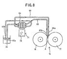
- a flexographicible supply tube (tube body) 65 and a flexographicible recovery tube (tube body ) 66 are both passed through a tubing pump 64 which is rotationally driven in a prescribed direction by means of a motor 70 provided on the support plate 35 of the transfer mechanism.
- the ink supply means is comprised of an actuating unit 71 (an ink transfer means ) including the motor 70 and the tubing pump 64 , and a supply tube 65.
- the ink recovery means is comprised of the actuating unit 71 and the recovery tube 66.
- An opening portion 65a of the supply tube 65 is immersed in the flexographic ink in the ink pot 36 mounted on the support plate 35 , while an opening portion 65b of the supply tube 65 opens into the ink fountain A from above.
- an opening portion 66a of the recovery tube 66 is immersed in the.flexographic ink retained in the ink fountain A, while an opening portion 66b of the recovery tube 66 opens into the ink pot 36.
- the supply and recovery tubes 65, 66 are passed through the tubing pump 64, as shown in Figure 8, in such a way that the ink fountain A is supplied with flexographic ink from the ink pot 36 via the supply tube 65, while at the same time the flexographic ink in the ink fountain A is recovered to be returned to the ink pot 36 via the recovery tube 66.
- the flexographic ink in the ink fountain A is circulated due to the fact that the ink fountain A is supplied with flexographic ink from the ink pot 36 via the supply tube 65, while at the same time the flexographic ink in the ink fountain A is recovered to be returned to the ink pot 36 via the recovery tube 66.
- the flexographic ink is effectively circulated through the entire width of the ink fountain A due to the ink being supplied and recovered while the carriage 30 is being moved to the right or left.
- the opening portion 65a of the supply tube 65 is lifted out of the flexographic ink in the ink pot 36 by an appropriate means and the tubing pump 64 is rotationally driven in the same direction as that in which it is driven during the printing, while at the same time, the carriage 30 is moved to the right or left.
- the flexographic ink in the ink fountain A is recovered to be returned to the ink pot 36 via the recovery tube 66.
- the ink pot 36 is replaced with a washing pot containing the washing liquid, and only the opening portion 65a of the supply tube 65 is immersed in the washing liquid in the washing liquid pot, and then the tubing pump 64 is driven to supply the washing liquid from the washing liquid pot to the ink fountain A.
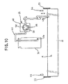
- Figures 9 and 10 show alternative embodiment of the flexographic ink printing machine (not according to the invention as disclosed in the independent claims) which is different from the one in the above-described embodiment in that only a single ink supply/recovery unit (ink transfer means) is provided.
- the fundamental structure of the ink supply/recovery unit is the same as the one described in connection with Figures 1 to 4. More specifically, the ink pot 36, which contains a prescribed amount of the flexographic ink, is removably mounted on the support plate 35, while only a single ink supply/recovery unit (the first ink supply/recovery unit ) 25 is provided.
- the tube ( tube body for ink) 41 of the ink supply/recovery unit 25 is immersed in the flexographic ink in the ink pot 36.
- the opening portion 41b is inserted into the ink fountain A to near the bottom thereof.
- the reversible motor 40 of the ink supply/recovery unit 25 is driven first in one direction and then in the opposite direction when printing is conducted, and this operation cycle is repeated at prescribed time intervals, whereby the ink fountain A is supplied with flexographic ink from the ink pot 36 and the flexographic ink in the ink fountain A is recovered to be returned to the ink pot 36.
- the reversible motor 40 is firstly driven in one direction (clockwise as seen in Figure 9 ) to supply the ink fountain A with flexographic ink from the ink pot 36 via the tube 41 Then, after a certain period of time, the flexographic ink in the ink fountain A is recovered to be returned to the ink pot 36 via the tube 41.
- the flexographic ink in the ink fountain A is thus kept in a fluid condition, that is, a dynamic condition that prevents stagnation, by repeating the supply and the recovery of the ink through the ink supply/recovery unit 25.
- the carriage 30 may move to the right or left, while at the same time, the flexographic ink is supplied from the ink pot 36 to the ink fountain A through the tube 41 by driving the reversible motor 40 in one direction, while on the other hand, the flexographic ink in the ink fountain A is recovered to be returned to the ink pot 36 through the tube 41 by driving the reversible motor 40 in the opposite direction.
- This enables the ink to be reciprocated through the tube 41 between the ink fountain A and the ink pot 36 during a predetermined time period.
- the total amount of the predetermined time periods between ink supply and ink recovery may preferably be less than or equal to three seconds, no matter how many times ink supply and ink recovery may be repeated.
- the ink supply/recovery unit 25 may be selectively moved along the ink fountain A or held in a stationary position.
- the printing machine described in the above embodiments is designed to use the flexographic ink, which needs to be circulated.
- the printing machine according to the embodiments can also be applied to glycolic ink, which has. low viscosity and dries very quickly.
- an ink pot containing the glycolic ink is mounted on the support plate, and one opening portion of the first tube of the first ink supply/recovery unit is immersed in the glycolic ink, while the other opening portion thereof is communicated with the ink fountain A from above. Then, when printing is conducted, the glycolic ink is supplied from the ink pot only by the first ink supply/recovery unit, the second ink supply/recovery unit having been halted.
- the residual ink in the ink fountain is recovered to be returned to the ink pot by the first ink supply/recovery unit. Since the glycolic ink does not need to be circulated, the amount of ink which was conventionally needed for circulating the ink can be saved, whereby inventory cost can be reduced.
- the first tube of the first ink supply/recovery unit serves not only as the ink supply path, but also as the ink recovery path.
- the tubing pump which is adopted as the ink supply/recovery unit may be replaced with a pump of a different type which can be energized forwardly and reversely.
- a pump which supplies the ink by pressurizing the inside of the tank containing the flexographic ink and recovers the ink by vacuumizing inside the tank can be adopted.
- the locating of the ink supply source adjacent to the ink fountain defined between the ink transfer roll and the regulating means enables the ink circulation system to be shortened, and the ink which is discharged needlessly to be greatly reduced, whereby a substantial amount of ink can be saved.
- the shortened ink circulation system enables the amount of washing liquid to be reduced when washing is conducted, whereby the amount of washing liquid discharged is markedly reduced, which is very advantageous from the standpoint of preventing pollution.
- the washing necessary when the color of the ink is changed in response to a printing order change can be conducted in a shorter time, thereby enabling small lot printing to be suitably conducted in accordance with various kinds of corrugated board sheets.
- the locating of the ink supply means and the ink recovery means adjacent to the ink fountain defined between the ink transfer roll and the regulating means enables the ink circulation system to be shortened, and the ink which is discharged needlessly to be greatly reduced, whereby a substantial amount of ink can be saved.
- the shortened ink circulation system enables the amount of washing liquid to be reduced when washing is conducted, whereby the amount of washing liquid discharged is markedly reduced, which is very advantageous from the standpoint of preventing pollution.
- the ink circulation system is comprised of a single ink transfer means and a single ink tube body, the amount of the ink discharged. needlessly can be further decreased, while at the same time the amount of the washing liquid required for washing can be reduced.
- the structure of the system can be simplified and thus the cost can be reduced.
Landscapes
- Inking, Control Or Cleaning Of Printing Machines (AREA)
Description
- The present invention relates to a printing machine, more particularly, to a printing machine capable of reducing the amount of ink discharged needlessly when a print order is changed.
- As disclosed in Japanese Patent Utility Model Laid-Open Application HEI 4-87244, a flexographic printing machine used for printing corrugated board sheets, is configured in such a way that the flexographic ink supplied to the space between an ink roll and a squeeze roll, both of which are rotationally disposed, is transmitted via the ink roll to a printing die mounted on a plate cylinder. Since the flexographic ink used in the flexographic printing machine dries very quickly, it has to be constantly circulated in order to prevent it from drying, and thus solidfying. Accordingly, the flexographic printing machine adopts a circulation mechanism which supplies the ink in the ink tank to the space between the ink and squeeze rolls via a pump and a supply tube, while on the other hand, it recovers the residual ink through the opposite end portions of both rolls, a tub member, and a recovery tube return it to the ink tank.
- In the above-described flexographic printing machine, the ink tank is disposed to be below the operation side (one end portion of each of the above rolls in the axial direction) of the printing machine. For this reason, the tube passage of the supply tube extends from the ink tank to a point that is approximately in the middle in the axial direction of the rolls and above the rolls. In addition, since the residual ink between the both rolls, which flows out from the opposite ends of the rolls, is received by tub members provided on the respective ends of the rolls, the length of the tube passage of the recovery tube is also long.
- In recent years, the printing has had to conduct small lot processing of corrugated board sheets in accordance with various types of orders, and this tendency is increasing year by year. For the printing machine such small lot processing means that the ink must be changed frequently within a limited time to enable printing of corrugated board sheets in small lots in accordance with various types of orders. However, as pointed out above, in the conventional flexographic printing machine which includes the long ink circulation system, the rolls and the circulation system need to be washed by a large amount of water when the color of the ink is changed, so that complete recovery of the ink is almost impossible, and as a result, a substantial amount of ink loss can occur. Further, from the standpoint of preventing pollution, an expensive facility for treating the waste liquid from the washing process is required. Still further, the process for changing the color of the ink takes a lot of time so that efficiency of production is lowered due to the increase in time lost.
- The present invention was accomplished to eliminate the disadvantages caused by the foregoing problems. The object of the present invention is to provide a printing machine capable of reducing the amount of the ink discharged needlessly due to a printing order change and the amount of the waste liquid produced through the washing process, while at the same time saving time required for the recovery and washing processes. The object of the invention is solved according to the invention by an apparatus having the features disclosed in
claim 1 and a method having the features disclosed in claim 2. Preferred embodiments are subject of the dependent claims. - The features of this invention that are believed to be novel are set forth specifically in the appended claims. The invention, together with the objects and advantages thereof, may best be understood by reference to the following description of the preferred embodiments taken in conjunction with the accompanying drawings in which:
- Figure 1 shows schematically a side view of the printing machine according to the first embodiment of the invention, illustrating a state where printing is being carried out onto a corrugated board sheet;
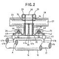
- Figure 2 shows schematically a front view of the major portion of the ink supply/recovery unit of the printing machine shown in Figure 1;
- Figure 3 shows schematically a perspective view of the ink transfer mechanism of the printing machine shown in Figure 1;
- Figure 4 shows a schematic illustration of the ink supply/recovery unit of the printing machine shown in Figure 1;
- Figure 5 shows a schematic illustration of the ink supply/recovery unit of the printing machine according to the second embodiment;
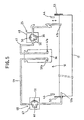
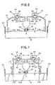
- Figure 6 shows a schematic illustration of the ink supply/recovery unit of the printing machine according to the third embodiment;
- Figure 7 shows a schematic illustration of the ink supply/recovery unit of the printing machine according to the fourth embodiment;
- Figure 8 shows a schematic illustration of the ink supply/recovery unit of the printing machine according to the fifth embodiment;
- Figure 9 shows schematically a front view of the major portion of the ink supply/recovery unit of the printing machine according to an alternative embodiment (not according to the invention as disclosed in the independent claims);
- Figure 10 shows a schematic illustration of the ink supply/recovery unit of the printing machine shown in Figure 9.
-
- Figure 1 shows schematically a side view of the printing machine according to the first embodiment of the invention, illustrating a state where printing is being carried out onto a corrugated board sheet. The printing .
machine 10 shown in Figure 1 has between a pair of machine frames 12 (only one machine frame is shown) spaced from each other with a predetermined distance therebetween in the direction orthogonal to the line of feeding acorrugated board sheet 11, aplate cylinder 14 on which aprinting die 13 can removably be mounted and animpression cylinder 15 disposed to oppose the plate cylinder in a vertical relationship such that theformer cylinder 14 and thelatter cylinder 15, which are designed to be rotatable in the different directions, may locate respectively above and below the passline of thecorrugated board sheet 11. - An
ink transfer mechanism 16 which transfers ink to the printing die 13 is disposed above theplate cylinder 14. Theink transfer mechanism 16 basically consists of anink transfer roll 17 which directly transfers the ink supplied thereto to theprinting die 13, asqueeze roll 18 which is brought into press contact with theink transfer roll 17 to squeeze the ink and regulate the amount of the ink to be transferred to the printing die 13 and aswing mechanism 19 for shifting theink transfer roll 17 within a predetermined angle centered on the rotary shaft of thesqueeze roll 18. Theink transfer roll 17 can be shifted, as will be described later, by selectively operating the swing mechanism between (1) the ink transferring position, where theink transfer roll 17 is brought into contact with theprinting die 13 to allow the ink to be transferred to the printing die 13 and (2) the ink removing position, where theink transfer roll 17 is spaced from theprinting die 13 to be unable to transfer the ink to the printing die 13. - Namely, the.
ink transfer roll 17 is disposed to be approachable and retractable relative to theplate cylinder 14, and theink transfer roll 17 is designed to be rotated in contact with theprinting die 13 mounted on theplate cylinder 14 when it approaches to theplate cylinder 14. Theink transfer roll 17 is of an anilox roll having very fine dents formed in a desired pattern on. the surface thereof, and each of these dents serves to retain a predetermined amount of the ink therein as well as to prevent scattering of the ink during rotation of the rolls. While an iron-containing metallic material is used for theink transfer roll 17, it is instead possible to use a metallic roll having a ceramic film formed on the surface thereof by detonation flame spraying, on which anilox is engraved. Alternatively, an iron roll with no anilox (only with plating) or a simple rubber roll can also suitably be used as theink transfer roll 17. - The
squeeze roll 18 disposed adjacent to theink transfer roll 17 is normally brought into contact with theink transfer roll 17 during operation of the printing machine and rotated at the same speed at or a lower speed than that of theroll 17 so as to regulate the amount of the ink on the surface of theroll 17 by squeezing the excessive ink. Thesqueeze roll 18 is preferably of an iron-containing metallic material or of a flexographicible material such as rubber. If a rubbery material is used for thesqueeze roll 18, it is advisable to select the hardness thereof, for example, within the shore hardness of 50 to 75 depending on the length of the roll. - The
swing mechanism 19 disposed in theink transfer mechanism 16, including theink transfer roll 17 and thesqueeze roll 18, is designed to shift theink transfer roll 17 within a predetermined angle centered on the rotary shaft of thesqueeze roll 18. Namely, a pair of brackets 20 (only one is shown) are pivotally supported on opposite ends of thesqueeze roll 18 supported rotatably between themachine frames 12, and theink transfer roll 17 is swingably supported on thesebrackets 20. Each of a pair of air cylinders 21(only one is shown) is pivotally mounted at one end on thecorresponding machine frame 12. Apiston rod 21a (only one is shown) of each of theair cylinders 21 is rotationally connected to the upper portion of thesupport brackets 20 on the side where theink transfer roll 17 is pivotally mounted. By actuating the pair ofair cylinders 21 in a synchronized way, theink transfer roll 17 can be selectively shifted between (1) the ink transferring position, where theink transfer roll 17 is brought into contact with theprinting die 13 to allow the ink to be transferred to theprinting die 13 and (2) the ink removing position, where theink transfer roll 17 is spaced from theprinting die 13 to be unable to transfer the ink to the printing die 13. Theswing mechanism 19 detects whether or not acorrugated board sheet 11 is being passed through between theplate cylinder 14 and theimpression cylinder 15 by means of a suitable detecting means ( not shown ). If nosheet 11 is detected, theink transfer roll 17 automatically moves away from the printing die 13. Since the mechanism for imparting rotation to therolls - A
stopper bolt 22 is provided on the lower end of each of thesupport brackets 20, and an adjustingshaft 23 is rotationally mounted between themachine frames 12 to face the lower part of thecorresponding support bracket 20. When theink transfer roll 17 is positioned at the ink transfer position, each of thestopper bolts 22 abuts against an associatedeccentric shaft 24 eccentrically provided on the adjustingshaft 23. The adjustingshaft 23 is adapted to be rotated by an actuating means such as a motor, or an air cylinder (not shown ). Accordingly, the position of theink transfer roll 17 in the ink transfer position can be finely adjusted by rotating theeccentric shafts 24 over the predetermined center angles by means of the actuating means. - An ink fountain A is defined between the
ink transfer roll 17 and thesqueeze roll 18 along the longitudinal direction thereof, when they are brought into press contact with each other. Ink supply/recovery units rolls recovery units - In view of the fact that the ink supply/
recovery units rolls 17, 18) , the moving mechanism will be described first. Abeam 27 is provided between themachine frames 12 at an upper position to extend parallel to therolls carriage 30 is disposed to ride on aguide rail 28 formed on the upper surface of thebeam 27 to be slidable along therail 28 via a pair ofrollers 29. A pair of sprockets 31 (only 5 one is shown) are rotatably supported on thebeam 27 to be spaced from each other with a predetermined distance therebetween in the longitudinal direction of thebeam 27, and onesprocket 31 can be rotated forwardly and . reversely by adrive motor 32. Anendless chain 33 is extended around thesesprockets 31 and fixed at a predetermined portion to thecarriage 30. Accordingly, by actuating thedrive motor 32 forwardly and reversely, thecarriage 30 can be reciprocated along theguide rail 28 as thechain 33 runs. In addition, thedrive motor 32 is controlled in such a way that its rotating direction is switched if either of a pair of positional sensors ( not shown ) , which are disposed to be apart from each other in the moving direction of thecarriage 30, detects thecarriage 30, so that thecarriage 30 reciprocates within a certain widthwise length of the ink fountain A. The rotating direction of themotor 32 may be controlled so as to determine the range over which thecarriage 30 can reciprocate, based on a signal from a rotation sensor such as an encoder provided on the rotation system of thedrive motor 32. - As shown in Figure 2, a pair of
brackets 34 are provided on thecarriage 30 to be spaced apart from each other in the moving direction of thecarriage 30. Thebrackets 34 hang down toward thesqueeze roll 18, and asupport plate 35 is disposed to be horizontally at the lower end of thebrackets 34. Anink pot 36 containing a prescribed amount of the flexographic ink is removably mounted on the region of thesupport plate 35 between thebrackets 34. When the color of the ink is changed due to a printing order change, theink pot 36 can be replaced. On the other hand, when a washing operation is to be conducted due to the color change, as described later, theink transfer roll 17 and thesqueeze roll 18 can be washed by mounting a washing liquid pot containing washing liquid (water) on the support plate, and then using the washing liquid in the washing pot. A pair of guide rolls 37 are rotationally mounted on the bottom surface of thesupport plate 35. The guide rolls 37 are designed to abut against aguide 38 which is disposed parallel to therolls carriage 30 and thesupport plate 35 can move smoothly. - A first ink supply/
recovery unit 25 is provided on the portion of thesupport plate 35 which extends outwardly from one of the brackets 34 ( the right one in Figure 2). The first ink supply/recovery unit 25 includes afirst tubing pump 39 and a firstreversible motor 40 which drives thefirst tubing pump 39, and a first flexographicible tube 41 ( a first tube body) is removably passed through thefirst tubing pump 39. The oneopening portion 41a of thetube 41 is immersed in the flexographic ink in theink pot 36, while theother opening portion 41b is mounted in afirst holder 42 and opens into the ink fountain A. Thefirst holder 42 is moved between the upper level and the lower level by a first lifting and loweringdevice 43 which is provided on thesupport plate 35. The upper level is set in such a way that theother opening portion 41b of thetube 41 is immersed in the flexographic ink in the ink fountain A. The liquid level of the ink is detected byliquid level sensors 44 which are described below. On the other hand, the lower level is set in such a way that theother opening portion 41b is positioned at the bottom portion of the ink fountain A in order to recover as much residual ink as possible. - In addition, a second ink supply/
recovery unit 26 is provided on the portion of thesupport plate 35 which extends outwardly from the other of the brackets 34 ( the left one in Figure 2). The second ink supply/recovery unit 26 has the same construction as the first ink supply/recovery unit 25. More specifically, it includes asecond tubing pump 45 and a secondreversible motor 46 which drives thesecond tubing pump 45, and a second flexographicible tube 47 (a second tube body) is removably passed through thetubing pump 45. The oneopening portion 47a of thetube 47 is immersed in the flexographic ink in theink pot 36, while theother opening portion 47b is mounted in asecond holder 48 and opens into the ink fountain A. Thesecond holder 48, like thefirst holder 42, is designed to be movable between an upper level and a lower level by a second lifting and loweringdevice 49 which is provided on thesupport plate 35 so that theother opening portion 47b of thesecond tube 47 can be positioned at a level where it is immersed in the flexographic ink, or at the bottom portion of the ink fountain A. As described above, since bothunits portions tubes units - Since the basic structure of the first and
second pumps first tubing pump 39 will be described. Thefirst tubing pump 39 is configured in such a way that the flexographic ink in thefirst tube 41 is forced out in the predetermined direction by squeezing thefirst tube 41 by means of a plurality ofrollers 50 which move along a predetermined route. Then, when the firstreversible motor 40 is driven in the forward direction to rotate therollers 50 of thefirst tubing pump 39 in the clock wise direction in Figures 2 and 4, the flexographic ink in thefirst tube 41 is pushed out toward theother opening portion 41b, whereby the flexographic ink in theink pot 36 is supplied to the ink fountain A. On the other hand, when the firstreversible motor 40 is driven in the reverse direction to rotate therollers 50 in the counterclockwise direction, the flexographic ink in thetube 41. is pushed out to the oneopening portion 41a, whereby the flexographic ink in the ink fountain Ais recovered to be returned to theink pot 36. In thesecond tubing pump 45, when the secondreversible motor 46 is driven in the forward direction to rotate therollers 50 in the clockwise direction, the flexographic ink in the ink fountain A is recovered to be returned to theink pot 36, and when the secondreversible motor 46 is driven reversely to rotate therollers 50 in the counterclockwise direction, the flexographic ink in theink pot 36 is supplied to the ink fountain A. - Namely, the flexographic ink in the
ink pot 36 is supplied to the ink fountain A by the first and second tubing pumps 39, 45, while the flexographic ink retained in the ink fountain A is recovered to be returned to theink pot 36 also by the first and second tubing pumps 39, 45. This accomplishes the circulation of the flexographic ink, which dries very quickly, thereby enabling such an ink to be prevented from drying, and thus solidifying. In addition, if thecarriage 30 is moved to the right or left by thedrive motor 32, the supply and the recovery of the flexographic ink can be conducted throughout the width of the ink fountain A, so that all of whole flexographic ink held in the ink fountain A can be efficiently circulated. In this embodiment, the driving direction of each of the first and secondreversible motors carriage 30. For instance, when thecarriage 30 is moved to the left in Figure 4 ( the forward direction of the second ink supply/recovery unit 26 ), ink is supplied by the first ink supply/recovery unit 25, while ink is recovered by the second ink supply/recovery unit 26. On the other hand, when thecarriage 30 is moved to the right ( the forward direction of the first ink supply/recovery unit 25 ), ink is recovered by the first ink supply/recovery unit 25, while ink is supplied by the second ink supply/recovery unit 26. In short, when thefirst tube 41 serves as an ink supply tube, the other tube, that is, thesecond tube 47 serves as an ink recovery tube, while, on the other hand, when thefirst tube 41 serves as an ink recovery tube, the other tube, that is, thesecond tube 47 serves as an ink supply tube. In addition, the first and secondreversible motors - As shown in Figure 1, a pair of air cylinders 52 (only one shown) are invertedly disposed on the
respective support brackets 20 via respective support members 51. Eachair cylinders 52 has apiston rod 52a and aplatelike control member 53 is mounted on thepiston rod 52a so as to be movable up and down. As shown in Figure 3, the ink fountain A, which is defined between therolls control members 53 to such an extent that they closely contact the corresponding axial end portions of theink transfer roll 17 and thesqueeze roll 18 due to the actuation of theair cylinders 52. This enables the flexographic ink, which is supplied from the ink supply/recovery units tub member 54 is disposed below each axial end portion of theink transfer roll 17 and thesqueeze roll 18. When a washing operation is to be conducted, thecontrol members 53 are lifted by actuating the air cylinders 52.to-open the ink fountain A, and as a.result, the washing liquid which flows out from the ink fountain Ais received in thetub members 54, and is then recovered in anink pan 55 described below. - The
liquid level sensors 44 are disposed adjacent to and above the respective axial end portions of the ink fountain A in order to detect the liquid level of the flexographic ink in the ink fountain A when a printing operation is conducted. Thesensors 44 are adapted to effect detection as required to control the operation of the first and second ink supply/recovery units - A
scraper 56, which is comprised of an elongated blade-like plate for wiping the flexographic ink off when the color of the ink is changed in response to an order change, is provided adjacent and to thesqueeze roll 18. The tip of thescraper 56 lies tangent to thesqueeze roll 18 and points in the direction opposite from the direction of rotation of thesqueeze roll 18. This enables thescraper 56 to be swung in a forward direction and in a reverse direction by anair cylinder 57 to engage and disengage with the surface of theroll 18. When a washing operation is conducted, the washing liquid, which has been transferred to theroll 18, is scraped off, and thus removed by actuating anair cylinder 57 to cause thescraper 56 to contact thesqueeze roll 18. Then, the removed washing liquid is discharged to theink pan 55 which is disposed below thescraper 56. In addition, awaste liquid tube 58, which communicates with a waste liquid tank ( not shown ), is connected to theink pan 55, so that the waste liquid discharged to theink pan 55 can be collected to an appropriately located waste liquid tank. When the washing operation is to'be conducted, theink transfer roll 17 is adapted to be shifted about the rotary shaft of thesqueeze roll 18 by theswing mechanism 19 which is provided in conjunction with theink transfer mechanism 16, and thus to assume the ink washing position which is spaced apart from the printing die 13. - Now the operation of the flexographic printing machine configured in the foregoing manner will be described. When a printing operation is to be carried out, the
control members 53 provided at the opposite axial ends of theink transfer roll 17 and thesqueeze roll 18 are positioned at their lower levels to close the ends of the ink fountain A in the longitudinal direction. In addition, thecarriage 30 is positioned at the right end portion of the ink fountain A, and the first andsecond holders recovery units devices portions portions second tubes ink pot 36 mounted on thesupport plate 35. - The
drive motor 32 is then driven in the predetermined direction to move thecarriage 30 to the left, while at the same time the first and secondreverse motors rollers 50 of thefirst tubing pump 39 rotate clockwise to squeeze thefirst tube 41 in order to force the flexographic ink therein out to the side of theother opening portion 41b. Namely, the flexographic ink in theink pot 36 is supplied to the space (the ink fountain A) between theink transfer roll 17 and thesqueeze roll 18, both of which are rotating, via thefirst tube 41 by continuously squeezing thefirst tube 41 by means of therollers 50. This flexographic ink is dammed by thecontrol members 53 which force to open the ends of therolls rollers 50 of thesecond tubing pump 45 rotate in the clockwise direction to squeeze thesecond tube 47 in order to force the flexographic ink therein out to the side of the oneopening portion 47a. Namely, the flexographic ink, which is supplied from the first ink supply/recovery unit 25 to the ink fountain A, is recovered to be returned to theink pot 36 via thesecond tube 47 by continuously squeezing thesecond tube 47 by means of therollers 50. - In this way, the flexographic ink is circulated due to the fact that the flexographic ink is supplied to the ink fountain A by the first ink supply/
recovery unit 25, while at the same time the flexographic ink in the ink fountain A is recovered to be returned to theink pot 36 by the ink supply/recovery unit 26. This reliably prevents the flexographic ink, which dries very quickly, from getting dry, and thus solid. As described above, since the rotation of the first and secondreverse motors - Further, when the
carriage 30 is detected by the left positional sensor, thedrive motor 32 is reversed to move thecarriage 30 to the right, while at the same time the first and secondreverse motors ink pot 36 via thefirst tube 41 by means of thefirst tubing pump 39, while at the same time the flexographic ink in theink pot 36 is supplied to the ink fountain A via thesecond tube 47 by means of thesecond tubing pump 45. - When the
corrugated board sheets 11 are fed one by one to between theplate cylinder 14 and theimpression cylinder 15 from a stocker ( not shown ) situated upstream, under the condition that flexographic ink is retained in the ink fountain A, theswing mechanism 19 starts to actuate in response to the detection of a sheet by a suitable detecting means, so that theink transfer roll 17 of theink transfer mechanism 16 is brought into contact with the plate cylinder 14 ( the printing die 13) , whereby an appropriate amount of the flexographic ink is transferred to the surface of the printing die 13, followed by the predetermined printing on thesheet 11. Since the flexographic ink is highly quick-drying, the printed sheet can be fed to a die-cutter or a folder-gluer, etc. related to the subsequent procedure immediately after the printing operation is completed, In addition, since the flexographic ink is fed throughout between theink transfer roll 17 and thesqueeze roll 18, nonuniformity of color in the widthwise direction can be prevented, and thus the operator does not need to constantly monitor the printing condition. - When the flexographic ink is changed due to a color change in response to a printing order change, ink recovery and washing are conducted by a following procedure. When the passage of the
corrugated board sheets 11 between theplate cylinder 14 and theimpression cylinder 15 has been halted after the printing operation is completed, theink transfer roll 17 of theink transfer mechanism 16 is moved to the ink washing position, which is spaced apart from the plate cylinder 14 (the printing die 13), by theswing mechanism 19. Firstly, the rotations of theink transfer roll 17 and thesqueeze roll 18 halted with the first and thesecond holders portions second tubes reversible motor 40 is driven reversely while at the same time the secondreversible motor 46 is driven forwardly, and as a result, the flexographic ink in the ink fountain A is recovered to be returned to theink pot 36 via bothtubes carriage 30 to the right or left so that the other openingportions tubes - Then, the
ink pot 36 to which the unused flexographic ink has been recovered is replaced with the washing liquid pot containing the washing liquid. Next, the oneopening portions tubes air cylinder 57 is actuated to contact thescraper 56 with thesqueeze roll 18 at an appropriate pressure, while theair cylinders 52 are actuated reversely to raise thecontrol members 53 and open the ink fountain A. Then, the washing liquid in the washing liquid pot is supplied to the ink fountain A via the ink supply/recovery units ink transfer roll 17 and thesqueeze roll 18 are rotated in an idling manner at the same peripheral speed while thecarriage 30 is moved to the right or left. In this way, the washing liquid washes off the flexographic ink supplied to the ink fountain A and adhering to therolls ink pan 55 viatub members 54. On the other hand, the washing liquid which adheres to the surface of thesqueeze roll 18 is scraped off and thus removed by thescraper 56, and then discharged to theink pan 55. Thetubes 41,47 ( the circulation system of the flexographic ink ) can be simultaneously washed due to the fact that the washing liquid in the washing liquid pot is supplied to the ink fountain A by means of both ink supply/recovery units carriage 30 is kept stationary ( for instance, substantially midway of the axial length of therolls 17,18). - After the above-described washing operation has been completed, the washing liquid pot mounted on the
support plate 35 is replaced with anotherink pot 36 containing the flexographic ink appropriate for the new order. The oneopening portions second tubes new ink pot 36. This completes the color change procedure. - In the flexographic ink printing machine of this embodiment, the flexographic ink in the ink fountain A, which is very quick to dry, can be prevented from getting dry and thus solid by constantly circulating the flexographic ink by the process of supplying and recovering the ink simultaneously by means of the two ink supply/
recovery units ink pot 36 is situated adjacent to the ink fountain A, the length of each of the twotubes tubes - In this embodiment, each of the first and second ink supply/
recovery units units tubes recovery units tubes ink pot 36 is replaced, or they have to be replaced by other tubes. Further, the washing liquid can be quickly supplied to the entirety of the ink fountain A by disposing the washing liquid supply tube on thesupport plate 35 and then moving thesupport plate 35 to the right or left while the washing liquid is supplied. - Still further, a nozzle for jetting compressed air may be provided on the
support plate 35 and used to blow the residual washing liquid in the ink fountain A toward the axial ends to be discharged into thetub members 54 while thecarriage 30 is moved to the right or left . In this case, the washing operation can be advantageously conducted in a shorter time. Means for regulating the amount of ink supplied to the ink transfer roll is not limited to the squeeze roll in the embodiment. The amount of ink at the surface of the ink transfer roll also can be regulated by utilizing a regulating plate ( an elongated plate), the tip end of which is directed along the direction in which the ink transfer roll rotates, in such a way that the space between the tip end of the regulating plate and the surface of the roll can be adjusted. - Figures 5 to 8 show general views of the ink supply/recovery mechanism portions of the flexographic printing machine in alternate embodiments. Since the fundamental construction of each of the ink supply/recovery mechanism portions in Figures 5 to 8 is identical with those described in conjunction with Figures 1 to 4, only the parts of these portions which are different from those in Figures 1 to 4 will now be explained. The parts of the respective ink supply/recovery mechanism portions in Figures 5 to 8 identical to those in Figures 1 to 4 will be designated by reference numbers the same as those given to said corresponding parts in Figures 1 to 4.
- In the second embodiment as shown in Figure 5, one ink supply/recovery unit 25 ( for instance, a first ink supply/
recovery unit 25 which serves as ink supply means) is. provided on thesupport plate 35. The first ink supply/recovery unit 25 is designed to operate to supply the ink fountain A with the flexographic ink in theink pot 36 when the printing is to be carried out. In addition, a dedicated recovery tube (tube body ) 59 extends through a control member 53 ( located on the opposite side of theink pot 36 from the first ink supply/recovery unit 25) so that one opening portion ( a recovery opening portion) 59a thereof opens into the ink fountain A, while anotheropening portion 59b thereof is inserted into theink pot 36. Thededicated recovery tube 59 is designed to be passed through arecovery tubing pump 60 provided at an appropriate location on theframework 12. Flexographic ink can be recovered from the ink fountain A and returned to theink pot 36 through thededicated recovery tube 59 by driving therecovery tubing pump 60 in a predetermined direction by means of amotor 67. More specifically, in this embodiment, an ink recovery device ( ink transfer means ) 68 is comprised of the dedicatedrecovery ink tube 59, therecovery tubing pump 60 and themotor 67. In this embodiment, the flexographic ink is circulated by supplying the ink fountain A with flexographic ink from theink pot 36 through the first ink supply/recovery unit 25, while at the same time recovering flexographic ink from the ink fountain A and returning it to theink pot 36 through thededicated recovery tube 59 of theink recovery unit 68. It is not essential that the first ink supply/recovery unit 25 (the carriage 30 ) be moved to the right or left when printing is conducted. The flexographic ink can be supplied from a position which remains stationary. In addition, when the washing of the rolls and circulation is to be conducted, only theink recovery unit 68 may be driven to recover the flexographic ink with the first ink supply/recovery unit 25 halted, or the first ink supply/recovery unit 25 may be reversely driven, in addition to theink recovery unit 68, to recover the ink. A direct washing operation can be carried out in a way similar to that described above with respect to the above embodiment. - In the third embodiment as shown in Figure 6, a first ink supply/
recovery unit 25 and a second ink supply/recovery unit 26 are configured to recover the ink only when printing is conducted. Anink tank 61 in which a certain amount of flexographic ink is contained is mounted at a position corresponding to that where the ink pot is mounted on thesupport plate 35 . A supply tube (tube body) 62 is connected to the bottom of thetank 61 and disposed above the ink fountain A. An opening portion ( supply opening portion) 62a of thesupply tube 62 is opened and closed by asolenoid valve 63. Namely, in this embodiment, anink supply unit 69 is comprised of thesupply tube 62 and thesolenoid valve 63. In addition, theink tank 61 is located at the middle of the width of the ink fountain A and above the ink fountain A, while other openingportions tubes recovery units recovery units - In this embodiment, the flexographic ink is circulated due to the fact that when the printing is to be conducted, the
opening portion 62a of thesupply tube 62 is opened by thesolenoid valve 63 of theink supply unit 69 to supply the ink fountain A with the flexographic ink from theink tank 61, while at the same time the flexographic ink is recovered to be returned to theink tank 61 by the two ink supply/recovery units recovery units ink tank 61 by the two ink supply/recovery units portions tubes units ink tank 61 with a washing liquid tank in which the washing liquid is reserved, and then supplying the ink fountain A with the washing liquid in the washing tank, or supplying the ink fountain A with the washing liquid via a washing liquid supply tube which is connected to an exterior supply source. - The construction of the fourth embodiment as shown in Figure 7 is basically the same as that of the third embodiment except that the system is designed so that the flexographic ink can be supplied and recovered while the entire system is moved in the widthwise direction of the ink fountain A.
- In the fifth embodiment as shown in Figure 8, a flexographicible supply tube (tube body) 65 and a flexographicible recovery tube (tube body ) 66 are both passed through a
tubing pump 64 which is rotationally driven in a prescribed direction by means of amotor 70 provided on thesupport plate 35 of the transfer mechanism. In this embodiment, the ink supply means is comprised of an actuating unit 71 (an ink transfer means ) including themotor 70 and thetubing pump 64 , and asupply tube 65. The ink recovery means is comprised of theactuating unit 71 and therecovery tube 66. Anopening portion 65a of thesupply tube 65 is immersed in the flexographic ink in theink pot 36 mounted on thesupport plate 35 , while anopening portion 65b of thesupply tube 65 opens into the ink fountain A from above. On the other hand, anopening portion 66a of therecovery tube 66 is immersed in the.flexographic ink retained in the ink fountain A, while anopening portion 66b of therecovery tube 66 opens into theink pot 36. The supply andrecovery tubes tubing pump 64, as shown in Figure 8, in such a way that the ink fountain A is supplied with flexographic ink from theink pot 36 via thesupply tube 65, while at the same time the flexographic ink in the ink fountain A is recovered to be returned to theink pot 36 via therecovery tube 66. - In this embodiment, the flexographic ink in the ink fountain A is circulated due to the fact that the ink fountain A is supplied with flexographic ink from the
ink pot 36 via thesupply tube 65, while at the same time the flexographic ink in the ink fountain A is recovered to be returned to theink pot 36 via therecovery tube 66. When printing is conducted, the flexographic ink is effectively circulated through the entire width of the ink fountain A due to the ink being supplied and recovered while thecarriage 30 is being moved to the right or left. In addition, when a recovery is conducted, theopening portion 65a of thesupply tube 65 is lifted out of the flexographic ink in theink pot 36 by an appropriate means and thetubing pump 64 is rotationally driven in the same direction as that in which it is driven during the printing, while at the same time, thecarriage 30 is moved to the right or left. As a result, the flexographic ink in the ink fountain A is recovered to be returned to theink pot 36 via therecovery tube 66. When the washing is conducted in this embodiment, theink pot 36 is replaced with a washing pot containing the washing liquid, and only theopening portion 65a of thesupply tube 65 is immersed in the washing liquid in the washing liquid pot, and then thetubing pump 64 is driven to supply the washing liquid from the washing liquid pot to the ink fountain A. - Figures 9 and 10 show alternative embodiment of the flexographic ink printing machine (not according to the invention as disclosed in the independent claims) which is different from the one in the above-described embodiment in that only a single ink supply/recovery unit (ink transfer means) is provided. The fundamental structure of the ink supply/recovery unit is the same as the one described in connection with Figures 1 to 4. More specifically, the
ink pot 36, which contains a prescribed amount of the flexographic ink, is removably mounted on thesupport plate 35, while only a single ink supply/recovery unit ( the first ink supply/recovery unit ) 25 is provided. The tube ( tube body for ink) 41 of the ink supply/recovery unit 25 is immersed in the flexographic ink in theink pot 36. Theopening portion 41b is inserted into the ink fountain A to near the bottom thereof. Further, in this embodiment, thereversible motor 40 of the ink supply/recovery unit 25 is driven first in one direction and then in the opposite direction when printing is conducted, and this operation cycle is repeated at prescribed time intervals, whereby the ink fountain A is supplied with flexographic ink from theink pot 36 and the flexographic ink in the ink fountain A is recovered to be returned to theink pot 36. - In this embodiment, when the printing is conducted, the
reversible motor 40 is firstly driven in one direction (clockwise as seen in Figure 9 ) to supply the ink fountain A with flexographic ink from theink pot 36 via thetube 41 Then, after a certain period of time, the flexographic ink in the ink fountain A is recovered to be returned to theink pot 36 via thetube 41. The flexographic ink in the ink fountain A is thus kept in a fluid condition, that is, a dynamic condition that prevents stagnation, by repeating the supply and the recovery of the ink through the ink supply/recovery unit 25. - Further, when the printing is conducted, the
carriage 30 may move to the right or left, while at the same time, the flexographic ink is supplied from theink pot 36 to the ink fountain A through thetube 41 by driving thereversible motor 40 in one direction, while on the other hand, the flexographic ink in the ink fountain A is recovered to be returned to theink pot 36 through thetube 41 by driving thereversible motor 40 in the opposite direction. This enables the ink to be reciprocated through thetube 41 between the ink fountain A and theink pot 36 during a predetermined time period. In view of preventing the viscosity of the ink from changing with the passage of time, the total amount of the predetermined time periods between ink supply and ink recovery may preferably be less than or equal to three seconds, no matter how many times ink supply and ink recovery may be repeated. - In addition, when recovery and washing are conducted, the residual flexographic ink in the ink fountain A is recovered to be returned to the
ink pot 36 by rotationally driving thereversible motor 40 only in the reverse direction. When the printing is conducted, or the recovery/washing is conducted, the ink supply/recovery unit 25 may be selectively moved along the ink fountain A or held in a stationary position. - The printing machine described in the above embodiments is designed to use the flexographic ink, which needs to be circulated. The printing machine according to the embodiments can also be applied to glycolic ink, which has. low viscosity and dries very quickly. For instance, in the . embodiment shown in Figures 1 to 4, an ink pot containing the glycolic ink is mounted on the support plate, and one opening portion of the first tube of the first ink supply/recovery unit is immersed in the glycolic ink, while the other opening portion thereof is communicated with the ink fountain A from above. Then, when printing is conducted, the glycolic ink is supplied from the ink pot only by the first ink supply/recovery unit, the second ink supply/recovery unit having been halted. On the other hand, when recovery and washing are conducted, the residual ink in the ink fountain is recovered to be returned to the ink pot by the first ink supply/recovery unit. Since the glycolic ink does not need to be circulated, the amount of ink which was conventionally needed for circulating the ink can be saved, whereby inventory cost can be reduced. In this configuration, the first tube of the first ink supply/recovery unit serves not only as the ink supply path, but also as the ink recovery path.
- The tubing pump which is adopted as the ink supply/recovery unit may be replaced with a pump of a different type which can be energized forwardly and reversely. For instance, a pump which supplies the ink by pressurizing the inside of the tank containing the flexographic ink and recovers the ink by vacuumizing inside the tank, can be adopted.
- As described above, according to the present invention, the locating of the ink supply source adjacent to the ink fountain defined between the ink transfer roll and the regulating means enables the ink circulation system to be shortened, and the ink which is discharged needlessly to be greatly reduced, whereby a substantial amount of ink can be saved. In addition, the shortened ink circulation system enables the amount of washing liquid to be reduced when washing is conducted, whereby the amount of washing liquid discharged is markedly reduced, which is very advantageous from the standpoint of preventing pollution. Further, owing to this shortened ink circulation system, the washing necessary when the color of the ink is changed in response to a printing order change can be conducted in a shorter time, thereby enabling small lot printing to be suitably conducted in accordance with various kinds of corrugated board sheets.
- As described above, according to another embodiment of the present invention, the locating of the ink supply means and the ink recovery means adjacent to the ink fountain defined between the ink transfer roll and the regulating means enables the ink circulation system to be shortened, and the ink which is discharged needlessly to be greatly reduced, whereby a substantial amount of ink can be saved. In addition, the shortened ink circulation system enables the amount of washing liquid to be reduced when washing is conducted, whereby the amount of washing liquid discharged is markedly reduced, which is very advantageous from the standpoint of preventing pollution. Further, owing to this shortened circulation system, the washing necessary when the color of the ink is changed in response to a printing order change can be conducted in a shorter time, thereby enabling small lot printing to be suitably conducted in accordance with various kinds of corrugated board sheets.
- In addition, according to still another embodiment of the present invention, since the ink circulation system is comprised of a single ink transfer means and a single ink tube body, the amount of the ink discharged. needlessly can be further decreased, while at the same time the amount of the washing liquid required for washing can be reduced. In addition, the structure of the system can be simplified and thus the cost can be reduced.
- The present invention has been described with reference to the preferred embodiments thereof which are intended to be illustrative rather than limiting. Various changes and modifications may be made without departing from the scope of the present invention in the following claims.
Claims (4)
- An apparatus for preventing an ink from getting dry and thus becoming solid comprising:an ink reservoir (36; 61) for the ink; andmeans for circulating the ink between said ink reservoir (36; 61) and an ink fountain (A) by supplying the ink from said ink reservoir (36; 61) to said ink fountain (A) while at the same time recovering the ink from said ink fountain (A) to said ink reservoir (36; 61); said circulating means comprising:an ink supply tube body (41; 47; 62; 65) for supplying the ink from the ink reservoir (36; 61) to said ink fountain (A);an ink recovery tube body (41; 47; 59; 66) for recovering the ink from the ink fountain (A) to the ink reservoir (36; 61); andmeans (39; 45; 60; 64) for transferring the ink between said ink fountain (A) and said ink reservoir (36; 61);one open end (41a; 47a;65a) of said ink supply tube body (41; 47; 62; 65) communicates with the ink reservoir (36; 61) and another open end (41b; 47b; 62a; 65b) thereof opens into the ink fountain (A);one open end (41a; 47a; 59b; 66b) of said ink recovery tube body (41, 47; 59; 66) communicates with the ink reservoir (36; 61) and another open end (41b; 47b; 59a; 66a) thereof opens into the ink fountain (A).
- A method for preventing an ink from getting dry and thus becoming solid by utilizing an apparatus according to claim 1 for supplying and recovering the ink including an ink reservoir (36; 61) for the ink, an ink supply/recovery tube body (41; 47; 59; 62; 65; 66) for supplying the ink from the ink reservoir (36; 61) to an ink fountain (A) and for recovering the ink from the ink fountain (A) to the ink reservoir (36; 61), and means (39; 45; 60; 64) for transferring the ink between said ink fountain (A) and said ink reservoir (36; 61); said method comprising the step of:keeping the ink in said ink fountain (A) in a fluid condition by supplying the ink from said ink reservoir (36; 61) to said ink fountain (A) while at the same time recovering the ink from said ink fountain (A) to said ink reservoir (36; 61), while the ink is being transferred between said ink fountain (A) and said ink reservoir (36; 61) by said transferring means (39; 45; 60; 64).
- The method according to claim 2, wherein said ink supply/recovery tube body (41; 47; 59; 62; 65; 66) comprising an ink supply tube body (41; 47; 62; 65) for supplying the ink from the ink reservoir (36; 61) to said ink fountain (A) and an ink recovery tube body (41, 47; 59; 66) for recovering the ink from the ink fountain (A) to the ink reservoir (36; 61);
whereby the ink being circulated between said ink reservoir (36; 61) and said ink fountain (A) by supplying the ink from said ink reservoir (36; 61) to said ink fountain (A) while at the same time recovering the ink from said ink fountain (A) to said ink reservoir (36; 61). - The method according to claim 2, wherein said ink transferring means (39,45;60;64) is adapted to be able to change the direction of the ink transferred between said ink fountain (A) and said ink reservoir (36; 61) so as to transfer the ink forwardly and reversely;
whereby the ink is reciprocated between said ink reservoir (36; 61) and said ink fountain (A) by supplying the ink from said ink reservoir (36; 61) to said ink fountain (A) and recovering the ink from said ink fountain (A) to said ink reservoir (36; 61).
Applications Claiming Priority (3)
| Application Number | Priority Date | Filing Date | Title |
|---|---|---|---|
| JP10800098A JP3370600B2 (en) | 1998-04-17 | 1998-04-17 | Flexographic printing machine |
| JP10800098 | 1998-04-17 | ||
| EP19990107301 EP0950521B1 (en) | 1998-04-17 | 1999-04-19 | Apparatus and method for printing sheets |
Related Parent Applications (1)
| Application Number | Title | Priority Date | Filing Date |
|---|---|---|---|
| EP19990107301 Division EP0950521B1 (en) | 1998-04-17 | 1999-04-19 | Apparatus and method for printing sheets |
Publications (3)
| Publication Number | Publication Date |
|---|---|
| EP1260367A2 EP1260367A2 (en) | 2002-11-27 |
| EP1260367A3 EP1260367A3 (en) | 2002-12-11 |
| EP1260367B1 true EP1260367B1 (en) | 2003-09-03 |
Family
ID=14473453
Family Applications (2)
| Application Number | Title | Priority Date | Filing Date |
|---|---|---|---|
| EP19990107301 Expired - Lifetime EP0950521B1 (en) | 1998-04-17 | 1999-04-19 | Apparatus and method for printing sheets |
| EP02017933A Expired - Lifetime EP1260367B1 (en) | 1998-04-17 | 1999-04-19 | Apparatus and method for preventing ink from getting dry |
Family Applications Before (1)
| Application Number | Title | Priority Date | Filing Date |
|---|---|---|---|
| EP19990107301 Expired - Lifetime EP0950521B1 (en) | 1998-04-17 | 1999-04-19 | Apparatus and method for printing sheets |
Country Status (3)
| Country | Link |
|---|---|
| EP (2) | EP0950521B1 (en) |
| JP (1) | JP3370600B2 (en) |
| ES (2) | ES2198812T3 (en) |
Families Citing this family (8)
| Publication number | Priority date | Publication date | Assignee | Title |
|---|---|---|---|---|
| JP3581306B2 (en) * | 2000-03-31 | 2004-10-27 | 株式会社イソワ | Ink viscosity measuring device, ink viscosity adjusting method and device therefor |
| US6739256B1 (en) | 2002-05-17 | 2004-05-25 | Umetani Mfg. Co., Ltd. | Method of ink agitation by ink aspiration |
| DE60236917D1 (en) | 2002-05-17 | 2010-08-19 | Umetani Mfg Co Ltd | Printing method and printing machine for carrying out the method |
| CN100351081C (en) * | 2002-05-21 | 2007-11-28 | 梅谷制作所 | Printing method and printer using same |
| JP4002859B2 (en) * | 2002-12-27 | 2007-11-07 | 株式会社イソワ | Ink removal / recovery device, printing machine equipped with the device, and ink supply / recovery method |
| JP5164336B2 (en) * | 2005-07-19 | 2013-03-21 | 一夫 菱沼 | Ink supply device for printing press |
| WO2019092520A1 (en) * | 2017-11-09 | 2019-05-16 | Engico S.R.L. | A sheet processing system and method |
| CN114025966B (en) * | 2018-12-20 | 2023-12-08 | 博斯特佛罗伦萨有限公司 | Linear ink dispensing system |
Family Cites Families (8)
| Publication number | Priority date | Publication date | Assignee | Title |
|---|---|---|---|---|
| DE872783C (en) * | 1951-10-14 | 1953-04-09 | Texplant Corp | Ink pump for the printing units of textile printing devices |
| DE1926906A1 (en) * | 1969-05-27 | 1970-12-03 | Dornbusch & Co | Filling doctor device, in particular for coloring printing forms |
| JPH0487244A (en) | 1990-07-27 | 1992-03-19 | Hitachi Ltd | Scanning type electron microscope |
| US5265535A (en) * | 1991-12-28 | 1993-11-30 | Kabushiki Kaisha Isowa | Printing machine for corrugated board sheet |
| US5189955A (en) * | 1992-07-23 | 1993-03-02 | Su Shun Fa | Automatic inking mechanism for paperboard printing machines |
| JP2627865B2 (en) * | 1994-05-25 | 1997-07-09 | 株式会社丸松製作所 | Ink supply and cleaning device for rotary printing press |
| JPH08336955A (en) * | 1995-06-14 | 1996-12-24 | Isowa Corp | Ink supply-recovery apparatus in printing machine |
| US5697299A (en) * | 1996-02-09 | 1997-12-16 | Umetani Mfg. Co., Ltd. | Ink supplying and collecting device for use in printing presses |
-
1998
- 1998-04-17 JP JP10800098A patent/JP3370600B2/en not_active Expired - Fee Related
-
1999
- 1999-04-19 EP EP19990107301 patent/EP0950521B1/en not_active Expired - Lifetime
- 1999-04-19 EP EP02017933A patent/EP1260367B1/en not_active Expired - Lifetime
- 1999-04-19 ES ES99107301T patent/ES2198812T3/en not_active Expired - Lifetime
- 1999-04-19 ES ES02017933T patent/ES2201045T3/en not_active Expired - Lifetime
Also Published As
| Publication number | Publication date |
|---|---|
| JP3370600B2 (en) | 2003-01-27 |
| EP0950521A1 (en) | 1999-10-20 |
| EP1260367A2 (en) | 2002-11-27 |
| ES2201045T3 (en) | 2004-03-16 |
| EP0950521B1 (en) | 2003-07-23 |
| JPH11300933A (en) | 1999-11-02 |
| ES2198812T3 (en) | 2004-02-01 |
| EP1260367A3 (en) | 2002-12-11 |
Similar Documents
| Publication | Publication Date | Title |
|---|---|---|
| US5265535A (en) | Printing machine for corrugated board sheet | |
| US6928927B2 (en) | Intaglio printing press | |
| JPH072200Y2 (en) | Printer | |
| EP0382347B1 (en) | Printing apparatus with dual inking system | |
| CA2207814C (en) | Device for filling depressions in a cylinder; doctor blade device for this purpose and process for changing it | |
| EP1260367B1 (en) | Apparatus and method for preventing ink from getting dry | |
| EP0951998B1 (en) | Printing machine for corrugated board sheets and method of cleaning ink fountain of the machine | |
| US7434510B2 (en) | Method for cleaning the screen stencil of a silk-screen printing device | |
| JPH10157079A (en) | Printer for corrugated fiberboard sheet and its operating method | |
| JP3053666U (en) | Printer | |
| JPH08336955A (en) | Ink supply-recovery apparatus in printing machine | |
| JP2534949B2 (en) | Printing machine for corrugated sheet | |
| JP3523499B2 (en) | Printer | |
| JP2602428Y2 (en) | Flexographic printing machine | |
| JP2000280447A (en) | Ink supply device for printing press | |
| JP2777760B2 (en) | Corrugated sheet printing machine | |
| JP3002218U (en) | Ink supply / collection mechanism for corrugated board printing machine | |
| CN221584787U (en) | Double-color screen printer | |
| JPH0640015A (en) | Recovery method of ink of printer for corrugated board sheet | |
| CN117734295A (en) | Flexographic printing mechanism of flexible sensor | |
| CN117734296A (en) | Full-automatic non-woven fabric double-color screen printer | |
| JPH0688409B2 (en) | Ink discharge method and device for printing machine | |
| JP2000037857A (en) | Method and device for discharging liquid for printer | |
| JPH06262755A (en) | Printer for corrugated board sheet | |
| JPH05200985A (en) | Printing machine for corrugated board sheet |
Legal Events
| Date | Code | Title | Description |
|---|---|---|---|
| PUAI | Public reference made under article 153(3) epc to a published international application that has entered the european phase |
Free format text: ORIGINAL CODE: 0009012 |
|
| PUAL | Search report despatched |
Free format text: ORIGINAL CODE: 0009013 |
|
| 17P | Request for examination filed |
Effective date: 20020905 |
|
| AC | Divisional application: reference to earlier application |
Ref document number: 950521 Country of ref document: EP |
|
| AK | Designated contracting states |
Kind code of ref document: A2 Designated state(s): ES FR IT SE |
|
| AK | Designated contracting states |
Kind code of ref document: A3 Designated state(s): ES FR IT SE |
|
| GRAH | Despatch of communication of intention to grant a patent |
Free format text: ORIGINAL CODE: EPIDOS IGRA |
|
| GRAS | Grant fee paid |
Free format text: ORIGINAL CODE: EPIDOSNIGR3 |
|
| GRAA | (expected) grant |
Free format text: ORIGINAL CODE: 0009210 |
|
| AC | Divisional application: reference to earlier application |
Ref document number: 0950521 Country of ref document: EP Kind code of ref document: P |
|
| AK | Designated contracting states |
Kind code of ref document: B1 Designated state(s): ES FR IT SE |
|
| AKX | Designation fees paid |
Designated state(s): ES FR IT SE |
|
| REG | Reference to a national code |
Ref country code: SE Ref legal event code: TRGR |
|
| REG | Reference to a national code |
Ref country code: ES Ref legal event code: FG2A Ref document number: 2201045 Country of ref document: ES Kind code of ref document: T3 |
|
| ET | Fr: translation filed | ||
| PLBE | No opposition filed within time limit |
Free format text: ORIGINAL CODE: 0009261 |
|
| STAA | Information on the status of an ep patent application or granted ep patent |
Free format text: STATUS: NO OPPOSITION FILED WITHIN TIME LIMIT |
|
| 26N | No opposition filed |
Effective date: 20040604 |
|
| PGFP | Annual fee paid to national office [announced via postgrant information from national office to epo] |
Ref country code: ES Payment date: 20070403 Year of fee payment: 9 |
|
| PGFP | Annual fee paid to national office [announced via postgrant information from national office to epo] |
Ref country code: IT Payment date: 20070510 Year of fee payment: 9 |
|
| REG | Reference to a national code |
Ref country code: ES Ref legal event code: FD2A Effective date: 20080421 |
|
| PG25 | Lapsed in a contracting state [announced via postgrant information from national office to epo] |
Ref country code: ES Free format text: LAPSE BECAUSE OF NON-PAYMENT OF DUE FEES Effective date: 20080421 |
|
| PG25 | Lapsed in a contracting state [announced via postgrant information from national office to epo] |
Ref country code: IT Free format text: LAPSE BECAUSE OF NON-PAYMENT OF DUE FEES Effective date: 20080419 |
|
| PGFP | Annual fee paid to national office [announced via postgrant information from national office to epo] |
Ref country code: FR Payment date: 20100312 Year of fee payment: 12 |
|
| PGFP | Annual fee paid to national office [announced via postgrant information from national office to epo] |
Ref country code: SE Payment date: 20100409 Year of fee payment: 12 |
|
| REG | Reference to a national code |
Ref country code: SE Ref legal event code: EUG |
|
| REG | Reference to a national code |
Ref country code: FR Ref legal event code: ST Effective date: 20111230 |
|
| PG25 | Lapsed in a contracting state [announced via postgrant information from national office to epo] |
Ref country code: FR Free format text: LAPSE BECAUSE OF NON-PAYMENT OF DUE FEES Effective date: 20110502 |
|
| PG25 | Lapsed in a contracting state [announced via postgrant information from national office to epo] |
Ref country code: SE Free format text: LAPSE BECAUSE OF NON-PAYMENT OF DUE FEES Effective date: 20110420 |