-
This invention generally relates to rotors.
More specifically, the present invention relates to
spinning reel rotors, which are rotatively attached
to a reel unit of a spinning reel and for winding
fishing line around a spool that can shift back and
forth.
-
Spinning reels typically include a reel unit, a
rotor and a spool. The reel unit is mounted to a
fishing rod. The rotor is mounted rotatively to the
reel unit and is for guiding the fishing line. The
spool is for winding fishing line that has been
guided to it by the rotor. The rotor includes a
rotor unit mounted rotatively to the reel unit, and
a bail arm mounted pivotably to the rotor unit.
-
The rotor unit includes a cylindrical portion
mounted rotatively to the reel unit, and first and
second rotor arms having first and second connection
portions and first and second arm portions. The
first and second connection portions extend radially
outward from the rear end of the cylindrical
portion, and the first and second arm portions
extend frontward, curving from the first and second
connection portions and keeping a certain distance
to the cylindrical portion. At the rear end of the
cylindrical potion, there is a ring-shaped large-diameter
portion, whose diameter is larger than that
of the other portions, and the first and second
connection portions extend radially outward at
opposing positions of the outer circumferential
surface of the large-diameter portion.
-
The bail arm is mounted to the first and second
rotor arms, and is pivotable between a line-winding
posture and a line-releasing posture. When in the
line-winding posture, the bail arm guides fishing
line and winds it around the spool. The bail arm
includes first and second bail support members
mounted pivotably to the first and second rotor
arms, a line roller mounted rotatively to the front
end of the first bail support member, and a bail
connecting the first bail support member with the
second bail support member and guiding the fishing
line to the line roller.
-
In this type of spinning reel, when the handle
is turned, the rotor rotates, and fishing line,
which is guided by the bail arm to the spool, is
wound around the spool.
-
For such a spinning reel rotor, a reduction of
the weight is desirable, in order to improve the
rotational balance and facilitate handling during
casting. When the weight of the rotor is reduced,
the flexural strength between the connection
portions and the arm portions, and in particular the
flexural strength between the first connection
portion on the fishing line guiding side, to which
the line roller is mounted, and the first arm
portion, poses a limitation. More specifically, the
force acting on the line roller during the winding
of fishing line creates a force that spreads the
first arm portion to the outside. In order to
maintain a strength that can withstand this force,
the wall thickness of the first connection portion
and the first arm portion has to be thick. For this
reason, it is difficult to reduce the weight of this
portion.
-
In view of the above, there exists a need for a
spinning reel rotor which overcomes the above
mentioned problems in the prior art. This invention
addresses this need in the prior art as well as
other needs, which will become apparent to those
skilled in the art from this disclosure.
SUMMARY OF THE INVENTION
-
It is an object of the present invention to
provide a spinning reel rotor whose weight can be
reduced while maintaining its strength.
-
According to a first aspect of the present
invention, a spinning reel rotor, which is
rotatively attached to a reel unit of a spinning
reel and winds fishing line around a spool that can
shift back and forth, includes a rotor unit, a bail
arm and a cover member. The rotor unit includes a
cylindrical portion made of synthetic resin, which
is rotatable with respect to the reel unit, and
first and second rotor arms including first and
second connection portions extending radially
outward from opposing positions at an outer
circumferential surface of a rear end of the
cylindrical portion, and first and second arm
portions that extend frontward curving from the
first and second connection portions and keeping a
certain distance to the cylindrical portion. The
bail arm is for guiding fishing line to the spool on
a first rotor arm side, and is mounted pivotably
with respect to front ends of the first and second
rotor arms. The cover member, which is for
reinforcing the rotor unit and is made of a material
that is stronger than that of the rotor unit, is
disposed at least on an outer side of the first
rotor arm, such that a hollow can be formed inside.
-
In this rotor, the rotor unit is made of a
synthetic resin, so that it can be made lighter than
a metal rotor unit. However, since synthetic resins
have weak strength, the wall thickness of the rotor
arms has to be increased in order to maintain
flexural strength. To address this issue, the outer
side of the first rotor arm on which the force acts
during the winding of line is covered by a cover
member made of a material with high strength, thus
reinforcing the first rotor arm. The cover member
covers the first connection portion and the first
arm portion from the outside, and a hollow is formed
inside it, so that it is formed by three-dimensional
bending. Therefore, when the force acts on the
first rotor arm, a tensile force acts on the cover
member instead of a compression force, so that it
does not deform easily. At least the first rotor
arm portion, which is susceptible to forces from the
rotor unit, is reinforced by the cover member, so
that the acting forces can be received by the cover
member, and the wall thickness of the rotor unit can
be reduced, reducing its flexural strength. Thus,
the rotor can be made lighter while maintaining its
strength.
-
According to a second aspect of the present
invention, in a spinning reel rotor as in the first
aspect of the invention, the bail arm includes first
and second bail support members mounted pivotably to
the front ends of the first and second bail arm
portions respectively, a line roller for guiding
fishing line, which is mounted rotatively to a front
end of the first bail support member, and a bail,
which connects the first bail support member and the
second bail support member and guides fishing line
to the line roller, and the cover member is disposed
on an outer side of the first connection portion and
the first arm portion of the first rotor arm. With
this configuration, only the first rotor arm, on
which the forces act, is provided with a reinforcing
cover member, and a decorative light-weight cover
member can be provided on the second rotor arm, thus
making the rotor even lighter.
-
According to a third aspect of the present
invention, in a spinning reel rotor as in the second
aspect of the invention, the cover member is
disposed also on an outer side of the second
connection portion and the second arm portion of the
second rotor arm. With this configuration, also the
second rotor arm is provided with a cover member,
facilitating the rotational balance of the rotor.
-
According to a fourth aspect of the present
invention, in a spinning reel rotor as in any of the
first to third aspects of the invention, the cover
member is formed such that it also covers a rear
surface of the cylindrical portion. With this
configuration, the cover member is formed so as to
cover a rear surface of the cylindrical portion, so
that an even higher flexural strength of the cover
member can be maintained.
-
According to a fifth aspect of the present
invention, in a spinning reel rotor as in any of the
first to fourth aspects of the invention, the cover
member is made of a metal, wherein "metal" includes
stainless alloys and aluminum alloys. With this
configuration, it is easier to keep the flexural
strength of the cover member high. Furthermore, the
corrosion resistance of the cover member can be
improved in the case of stainless alloys, whereas
the die-casting process is facilitated in the case
of aluminum alloys, so that a variety of shapes can
be adopted.
-
According to a sixth aspect of the present
invention, in a spinning reel rotor as in any of the
first to fourth aspects of the invention, the cover
member is made of a fiber reinforced resin, wherein
"fiber" includes carbon fibers and glass fibers.
With this configuration, an even lighter weight can
be attained while maintaining the flexural strength.
-
These and other objects, features, aspects and
advantages of the present invention will become
apparent to those skilled in the art from the
following detailed description, which, taken in
conjunction with the annexed drawings, discloses a
preferred embodiment of the present invention.
BRIEF DESCRIPTION OF THE DRAWINGS
-
Referring now to the attached drawings which
form a part of this original disclosure:
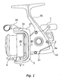
- Figure 1 is a lateral view of a spinning reel
in accordance with a first embodiment of the present
invention;
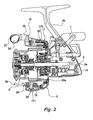
- Figure 2 is a lateral cross-sectional view of
the spinning reel in accordance with the first
embodiment of the present invention;
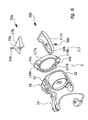
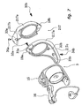
- Figure 3 is an exploded perspective view of the
rotor in accordance with the first embodiment of the
present invention;
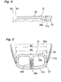
- Figure 4 is a cross-sectional view of the rotor
in accordance with the first embodiment of the
present invention viewed along line IV - IV in Fig.
1;
- Figure 5 is a cross-sectional view of the rotor
in accordance with the first embodiment of the
present invention viewed along line V - V in Fig. 1;
- Figure 6 is an exploded perspective view of the
rotor corresponding to Fig. 3, in accordance with a
second embodiment of the present invention;
- Figure 7 is an exploded perspective view of the
rotor corresponding to Fig. 3, in accordance with a
third embodiment of the present invention;
- Figure 8 is an exploded perspective view of the
rotor corresponding to Fig. 4, in accordance with a
fourth embodiment of the present invention;
- Figure 9 is an exploded perspective view of the
rotor corresponding to Fig. 5, in accordance with
the fourth embodiment of the present invention;
- Figure 10 is an exploded perspective view of
the rotor corresponding to Fig. 4, in accordance
with a fifth embodiment of the present invention;
- Figure 11 is an exploded perspective view of
the rotor corresponding to Fig. 5, in accordance
with the fifth embodiment of the present invention;
- Figure 12 is an exploded perspective view of
the rotor corresponding to Fig. 3, in accordance
with a sixth embodiment of the present invention;
- Figure 13 is an exploded perspective view of
the rotor corresponding to Fig. 4, in accordance
with the sixth embodiment of the present invention;
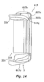
- Figure 14 is a lateral cross-sectional view of
the relevant rotor parts in accordance with a
seventh embodiment of the present invention;
- Figure 15 is a rear view of the relevant rotor
parts in accordance with an eighth embodiment of the
present invention;
- Figure 16 is a magnified cross-sectional view
of a spool in accordance with a ninth embodiment of
the present invention;
- Figure 17 is a magnified cross-sectional view
of a spool in accordance with a tenth embodiment of
the present invention; and
- Figure 18 is a magnified cross-sectional view
of a spool in accordance with an eleventh embodiment
of the present invention.
-
DETAILED DESCRIPTION OF THE PREFERRED EMBODIMENTS
-
As shown in Fig. 1, a spinning reel in
accordance with a first embodiment of the present
invention includes a reel unit 2, a rotor 3 disposed
at the front of the reel unit 2, and a spool 4
disposed at the front of the rotor 3. Then reel
unit 2 has a handle 1 and is mounted to a fishing
rod. The rotor 3 is rotatively mounted to the reel
unit 2. The spool 4 can shift back and forth with
respect to the reel unit 2.
-
The reel unit 2, which is made of a magnesium
alloy for example, includes a reel body 2a and a
roughly T-shaped rod attachment leg 2b extending
upward in Fig. 1 from the reel body 2a. A rotation
transmission mechanism (not shown in the drawings)
for transmitting rotation of the handle 1 to the
rotor 3 and an oscillating mechanism (not shown in
the drawings) for shifting the spool 4 back and
forth in synchronization with the handle 1 rotating
the rotor 3 are provided inside the reel body 2a.
At the lower rear end of the reel body 2a, there is
a protrusion protruding rearward for accommodating
the oscillating mechanism. In order to prevent the
damaging of this protrusion, a cover plate 10 made
of a hard metal such as a stainless alloy is fitted
to it. An insulating member 11 made of a synthetic
resin is fitted between the cover plate 10 and the
reel body 2a, in order to prevent electrolytic
corrosion of the reel unit 2.
-
As shown in Figs. 2 and 3, the rotor 3 includes
a rotor unit 15, a bail arm 16 and a reinforcing
cover member 17. The rotor unit 15 is mounted
rotatively to the reel unit 2. The bail arm 16 is
mounted pivotably to the front end of the rotor
unit. The cover member 17 is mounted detachably to
the lateral surface at the rear end of the rotor
unit 15.
-
The rotor unit 15, which is made of a synthetic
resin such as Nylon 66 for example, includes a
cylindrical portion 20, and first and second rotor
arms 21 and 22 formed in one piece with the
cylindrical portion 20. These components are made
with thin walls, in order to achieve a lighter
weight. The cylindrical portion 20, which is
mounted rotatively to the reel unit 2, includes at
its rear end a ring-shaped large-diameter portion
20a whose diameter is larger than that of the other
components.
-
The first and the second rotor arms 21 and 22
are formed in one piece with the large-diameter
portion 20a, at opposite positions on the outer
circumferential surface of the large-diameter
portion 20a. The first and second rotor arms 21 and
22 respectively include first and second connection
portions 21a and 22a extending radially outward from
the large-diameter portion 20a at opposite positions
on the outer circumferential surface of the large-diameter
portion 20a, and first and second arm
portions 21b and 22b curving out and extending
frontward from the first and second connection
portions 21a and 22a, keeping a certain distance to
the cylindrical portion 20.
-
The first and the second connection portions
21a and 22a which protrude from the outer
circumferential surface of the large-diameter
portion 20a, tapering off radially, are curved and
connected to the first and second arm portions 21b
and 22b. A rim protruding outward is formed at the
outer lateral faces of the first and second
connection portions 21a and 22a and the first and
second arm portions 21b and 22b, and a hollow is
formed in the outer lateral portion enclosed by the
rim portion. A bail tripping mechanism 30, which
holds the bail arm 16 in a line-winding posture or a
line-releasing posture and restores the bail arm 16
from the line-releasing posture to the line-winding
posture, is provided in the outer hollow at the
first rotor arm portion 21.
-
Of the first and the second connection portions
21a and 22a and the first and second arm portions
21b and 22b, a large force acts on the curved
portion between the first connection portion 21a and
the first arm portion 21b when the first rotor arm
21 tries to spread outward while winding up line.
However, since this force is received by the cover
member 17, the wall thickness of this portion can be
made thinner than conventionally, and a lighter
weight can be attained.
-
The purpose of the bail arm 16 is to guide
fishing line to the spool 4. The bail arm 16
includes first and second bail support members 25
and 26 mounted pivotably to the front ends of the
first and second rotor arms 21 and 22, respectively,
a line roller 27 mounted rotatively to the front end
of the first bail support member 25, and a curved
bail 29 made of a wire. The first bail support
member 25 includes a fixed shaft cover 28 flanking
the line roller 27, and the bail 29 links the fixed
shaft cover 28 and the second bail support member
26.
-
The cover member 17 reinforces the rotor unit
15 whose flexural strength is weakened by making its
walls thin to reduce weight, and covers the portions
of the rotor 3 that are prone to contact with other
objects, thus protecting the rotor 3 and keeping it
from being damaged. The cover member 17 is made of
a material that is stronger than the rotor unit 15,
such as a stainless alloy or an aluminum alloy, and
has high flexural strength. The cover member 17 can
be mounted from the rear side (right side in Fig. 2)
to the rotor unit 15, such that the cover member 17
covers the outer lateral space of the first and the
second rotor arms 21 and 22. As shown in Figs. 4
and 5, the cover member 17 is mounted to the rotor
unit 15 with its curved edges fitted against the
edges of the rotor unit 15, and is three-dimensionally
curved so that a hollow can be formed
inside.
-
The cover member 17 includes a first cover
portion 17a and a pair of second cover portions 17b
and 17c. The first cover portion 17a covers the
outer circumferential surface and the rear surface
of the large-diameter portion 20a, and the outer
lateral surfaces of the first and second connection
portions 21a and 22a. The pair of second cover
portions 17b and 17c extends frontward from both
ends of the first cover portion 17a and covers the
outer lateral surface of the first and second arm
portions 21b and 22b. A circular aperture 17d, into
which the rear end face of the cylindrical portion
20 is fitted, is formed in the middle of the first
cover portion 17a. The first cover portion 17a is
provided with boss portions 31a and 31b having
through holes, flanking the aperture 17d. The first
cover portion 17a is fastened to the rotor unit 15
with small screws 32a and 32b inserted into the boss
portions 31a and 31b. Also in the second cover
portions 17b and 17c, boss portions 33a and 33b with
through holes are formed, and they are fastened to
the rotor unit 15 with small screws 34a and 34b
inserted into the boss portions 33a and 33b.
-
The width-direction edges of the portions of
the first cover portion 17a and the second cover
portion 17b that cove the rotor unit 15 are, as
shown in Fig. 4 (first cover portion 17a) and Fig. 5
(second cover portion 17c), protrude beyond the two
width-direction edges of the rotor unit 15 in a
cross-section that intersects with the surface.
More specifically, the width dimensions W1 and W2 of
the first cover portion 17a and the second cover
portions 17b and 17c are 1 mm larger than the width
dimensions W3 and W4 of the large-diameter portion
20a of the rotor unit 15 and the rotor arm 22. With
these dimensions, the first and the second cover
portions 17a, 17b, and 17c protrude 0.5 mm at both
sides from the rotor unit 15. It is preferable that
the difference between the dimensions W1 and W2 is
in the range of 0.5 mm to 6 mm. If the difference
between the dimensions W1 and W2 of the first and
second cover portions 17a, 17b, and 17c and the
dimensions W3 and W4 of the rotor unit 15 is less
than 0.5 mm, then the first and the second cover
portions 17a, 17b, and 17c protrude only by 0.25 mm
at both sides. In that case, the level difference
to the rotor unit 15 becomes too small, so that the
components of the rotor unit 15 are prone to contact
with other object. On the other hand, if the
difference between the dimensions W1 and W2 and the
dimensions W3 and W4 exceeds 6 mm, then the
protrusion at both sides becomes too large, which
makes the level difference portion conspicuous and
unattractive, and leads to accumulation of foreign
matter such as dirt in the level difference portion.
-
The spool 4 is a cylindrical member with a
brim, around which the fishing line is wound. The
spool 4 is shifted back and force in synchronization
with the rotation of the rotor 3, such that fishing
line that is guided by the bail arm 16 is wound
substantially uniformly around the outer
circumferential surface of the spool 4.
-
With a spinning reel thus configured, a cover
member 17 with high flexural strength covers and
reinforces the curved portion of the connection
portions 21a and 22a. Therefore, the first rotor
arm 21 does not spread even when a force acts on the
line roller 27 in the direction spreading the first
rotor arm 21 during the winding of line.
Consequently, a sufficient flexural strength can be
ensured for the overall rotor, even when the
flexural strength of the rotor unit 15 is reduced by
making its walls thinner. Moreover, the cover
member 17 covers the rotor unit 15 and protrudes
from the rotor unit 15, so that the rotor unit 15 is
not prone to contact with other objects and is less
easily damaged. Therefore, the flexural strength of
the overall rotor is maintained at a sufficient
level, even when the flexural strength of the rotor
unit 15 is reduced by making the rotor unit 15 from
synthetic resin in order to reduce the weight of the
rotor 3.
Other Embodiments
-
- (a) In the preceding embodiment, the first cover
portion 17a and the pair of second cover portions
17b and 17c are formed in one piece, but as shown in
Fig. 6, they can also be formed separately. In that
case, first and second ears 118a and 118b can be
formed protruding outward at both ends of the first
cover portion 117a, the first cover portion 117a can
be fastened to the rotor unit 15, and the second
cover portions 117b and 117c can be fastened to the
connection portions 21a and 22a and to the arm
portions 21b and 22b, covering the ear portions 118a
and 118b. For this reason, the ear portions 118a
and 118b are provided with boss portions 31a and
31b, and small screws 32a and 32b are passed from
the second cover portions 117b and 117c through the
boss portions 31a and 31b to fasten the first cover
portion 117a and the second cover portions 117b and
117c to the rotor unit 15. It should be noted that
also the second cover portions 117b and 117c are
fastened to the rotor unit 15 with small screws 34a
and 34b passed through the boss portions 33a and
33b.
- (b) As shown in Fig. 7, it is also possible to
further provide a third cover portion 217e covering
the first cover portion 217a, forming the second
cover portion 217c and the first cover portion 217a
in one piece, and forming the second cover portion
217b and the third cover portion 217e in one piece.
In this case, the number of small screws that are
exposed at the rear end of the rotor 3 can be
reduced.
- (c) In the preceding embodiments, the cover member
17 is made of an aluminum alloy or a stainless
alloy, but it is also possible to make the cover
member 17 from a fiber-reinforced synthetic resin
that is reinforced by glass fibers or carbon fibers.
In that case, an even lighter weight can be achieved
while allowing the formation into any shape.
- (d) In the preceding embodiments, the cover member
17 is mounted by fitting it to the rear of the rotor
unit 15, but as shown in Figs. 8 and 9 as well as 10
and 11, it is also possible to mount it such that it
overlaps with the rear portion of the rotor unit
115.
In the embodiment shown in Figs. 8 and 9, the
cover member 317 is provided with a step portion
317f. The step portion 317f overlaps with the rotor
unit 115, covering the outer circumferential side of
the rotor unit 115. It should be noted that in this
embodiment, the rear end of the cylindrical portion
120 of the rotor unit 115 is not provided with a
large-diameter portion, but the rear end of the
cylindrical portion 120 is covered by the first
cover portion 317a.Furthermore, in the embodiment shown in Figs.
10 and 11, the outer circumferential portion of the
cylindrical portion 220 of the rotor unit 215 is
provided with a step portion 215a, which is covered
by the step portion 417f of the cover member 417.
In this embodiment, the amount of protrusion to the
outside can be made smaller than in the embodiment
shown in Figs. 8 and 9.
- (e) In the preceding embodiments, the cover member
17 is mounted to the rotor unit 15 by inserting
small screws from the cover member 17 side (from the
outer side). However, as shown in Fig. 12, it is
also possible to mount the first cover portion 517a
by inserting small screws 132a and 132b from the
rotor 15 side. Also, in this embodiment, the second
cover portion 517b is mounted to the arm portions
121b and 122b with a tongue-and-groove fitting,
instead of small screws. That is to say, as shown
in Figs. 12 and 13, the arm portions 121b and 122b
are each provided with a pair of first and second
protrusions 121c and 121d, and 122c and122d that are
parallel to the rotation axis of the rotor 3. The
protrusions 121c, 121d, 122c, and 122d protrude
facing inward, in opposition to one another. On the
other hand, coupling members 141, 142, 143, and 144,
respectively having coupling grooves 141a, 142a,
143a, and 144a at a position at which the coupling
members can be coupled with the protrusions 121c,
121d, 122c, and 122d are formed at the end of the
second cover portion 517b, 517c of the cover member
517. The coupling members 141-144 protrude toward
the arm portions 121b and 122b on the inner
peripheral side at the end of the second cover
portion 517b, 517c, and are provided in a pair,
parallel to the rotation axis of the rotor 3. When
mounting the cover member 517 to the rotor arm 15,
the coupling members 141-144 are coupled with the
rotor arm 15 in a sliding motion.
Instead of this tongue-and-groove coupling, it
is also possible to fasten the second cover portions
517b and 517c to the arm portions 121b and 122b with
small screws from an inner peripheral side.With this configuration, there are no small
screws or holes for attaching the small screws on
the outer side of the cover member 517, so that the
surface of the cover member 517 is smoother, its
design is preferable, and furthermore, foreign
matter such as dust does not adhere to it.
- (f) In the preceding embodiments, the cover member
17 covers the entire lateral surface of the rotor
unit 15, but it is also possible to devise it such
that it covers only the first rotor arm 21.
- (g) In the preceding embodiments, the first cover
portion 17a is fastened with small screws 32a and
32b to the rotor unit 15, but as shown in Fig. 14,
it is also possible to couple a coupling member 617g
formed at the first cover portion 617a by elastic
press-fitting with a counter-coupling portion 315b
formed at the end of the rotor unit 315. In this
case, the first cover portion 617a can be fixed
easily and securely.
In this embodiment, the first cover member 617a
and the second cover portions 617b and 617c are
formed in one piece. The second cover portions 617b
and 617c can be fastened with small screws to the
first arm portion 21b and the second arm portion
22b, or instead of with small screws, they can also
be attached to the first arm portion 21b and the
second arm portion 22b by tongue-and-groove fitting,
as shown in Fig. 12. If the second cover portions
617b and 617c are attached by tongue-and-groove
fitting, then the first cover portion 617a is
coupled elastically by press-fitting to the rotor
unit 315, and the second cover portions 617b and
617c, which are formed in one piece with the first
cover portion 617a, are fitted by tongue-and-groove
fitting in a sliding manner to the first arm portion
21b and the second arm portion 22b, so that the
mounting of the first cover portion 617a and the
second cover portions 617b and 617c is further
facilitated. Furthermore, it is not necessary to
provide small screws or holes for attaching the
small screws, so that the overall configuration is
simplified.Furthermore, as shown in Fig. 15, it is also
possible to form the first cover portion 717a and
the second cover portions 717b and 717c separately,
to couple the first cover portion 717a by elastic
press-fitting with the rotor unit 415, and further
fasten it at two locations with small screws 35a and
35b. In this case, the first cover portion 717a is
fastened even more securely. Furthermore, the first
cover portion 717a can be provided with stopping
portions 717h and 717i that are pressed down by the
second cover portions 717b and 717c when mounting
the second cover portions 717b and 717c, and that
are formed protruding on the sides of the second
cover portions 717b and 717c. In this case, the
small screws 35a and 35b can be kept from standing
out of the first cover portion 717a.
- (h) A spool of spinning reel disclosed in this
invention may be shaped as shown in Figs. 16 to 18.
Shown in Fig. 16, the spool 104 is fitted via a
drag mechanism 60 onto the front end of the spool
shaft 12. The spool 104 includes a bobbin trunk 7
made of synthetic resin, front and rear flange
portions 8a and 8b with a large diameter disposed to
the both sides of the bobbin trunk 7, a skirt
portion 9 extending rearward from an outer
peripheral portion of the rear flange portion 8b,
and a nut member 13 for fastening the rear flange
portion 8b and the skirt portion 9 to the bobbin
trunk 7.
-
-
The bobbin trunk 7 is made of a synthetic resin
such as Nylon 66, which is mounted pivotably to the
spool shaft 12 for winding fishing line around it.
The bobbin trunk 7 is a cylindrical member, and the
drag mechanism 60 is attached to its inner
circumference. At the rear end of the bobbin trunk
7, a rearward-protruding male threaded portion 7a to
which the nut member 13 is screwed is formed. The
front end of the bobbin trunk 7 is formed in one
piece with the front flange portion 8a. A
cylindrical jacket member 14 is attached to the
outer peripheral surface of the bobbin trunk 7. The
jacket member 14 can be made, for example, of metal
by press-forming a thin sheet material of 0.6 mm
thick aluminum alloy. The jacket member 14 is
provided to reinforce the bobbin trunk 7 made of
synthetic resin and to improve its appearance. The
front end of the jacket member 14 curves slightly
upward to the front flange portion 8a. The jacket
member 14 is formed in one piece with the rear
flange portion 8b and the skirt portion 9, together
forming a cylindrical shape with two different
levels. Thus, by making the rear flange portion 8b
and the skirt portion 9 from a thin sheet of light-weight
metal, the weight of the spool 104 can be
reduced, and an attractive appearance with metal
luster can be attained. A through hole 14a for
receiving a knot at the wind-starting end of the
fishing line is formed near the rear flange portion
8b.
-
A drag sounding mechanism 93 that makes a sound
when activating the drag mechanism 60 is fitted into
the bobbin trunk 7. A pair of front and rear
bearings 55 and 56 is fitted along an inner
peripheral side of the bobbin trunk 7, and the
bobbin trunk 7 is mounted rotatively on the spool
shaft 12 via the bearings 55 and 56.
-
The front flange portion 8a is a brim-shaped
member made of a synthetic resin formed in one piece
with the bobbin trunk 7, as described below. A
depression is formed at the outer peripheral portion
of the front flange portion 8a that comes into
contact with the fishing line, and a cover member 19
made by curling a (for example 0.6 mm thick) sheet
of a hard metal, such as a stainless alloy, is
fitted to it. The cover member 19 is mounted so as
to protect from damage that portion of the
relatively soft and easily damaged front flange
portion 8a made of synthetic resin that comes in
contact with the fishing line. The cover member 19
is bent over by curling from an outer front surface
of the front flange portion 8a over an outer
peripheral portion to an inner rear surface of the
front flange portion 8a. The end of the rear
surface of the cover member 19 abuts against the
curved portion at the front of the jacket member 14.
-
It is also possible to prevent damage by
providing the front flange portion 8a separately
from the bobbin trunk 7 and making the entire flange
portion 8a of a stainless alloy. However, if the
entire front flange portion 8a is made of a
stainless alloy, then the front flange portion 8a
becomes heavy, which stands in the way of making the
spool 104 lighter. To solve this problem, the cover
member 19, which is made of a hard thin sheet
material, covers that portion of the light-weight
synthetic resin front flange portion 8a that comes
into contact with the fishing line, thereby
achieving a lighter weight while protecting the
front flange portion 8a from damage, and maintaining
the abrasion resistance and the durability of the
front flange portion 8a.
-
The rear flange portion 8b is a disk-shaped
portion, and the male threaded portion 7a of the
bobbin trunk 7 protrudes from its rear end.
-
The skirt portion 9 is a cylindrical portion
extending rearward from an outer peripheral portion
of the rear flange portion 8b. The skirt portion 9
is provided with a stepped recess 9a, to which a
fishing line lock 50 for locking the front end of
the fishing line is attached. Between the recess 9a
and the fishing line lock 50, there is a gap for
clipping the fishing line.
-
The nut member 13 fastens the jacket member 14,
the rear flange portion 8b and the skirt portion 9,
which have been formed in one piece, to the bobbin
trunk 7 by screwing them to the male threaded
portion 7a. The nut member 13 is an elastic ring-shaped
member made of a synthetic resin, at the
center of which a female threaded portion 13a being
screwed to the male threaded portion 7a is formed.
Tool-interlock portions 13b for interlocking with a
special tool for turning the nut member 13 is formed
at the rear surface of the nut member 13 at a
certain spacing in circumferential direction. The
fishing-line lock 50, which is an elastically
deformable component roughly T-shaped in lateral
cross-section, is mounted to a projection 13c formed
projecting on the rear end of the nut member 13, and
is fastened by a pushnut 51 fitted over the tip of
the projection 13c.
-
In the course of assembling a spool 104 with
this configuration, the jacket member 14 is mounted
to the bobbin trunk 7 when the cover member 19 has
been fitted to the front flange portion 8a in a
curling process during the manufacture. In this
situation, the fishing line lock 50 is fastened to
the nut member 13, the bobbin trunk 7 is rotated
with respect to the nut member 13 to screw the male
threaded portion 7a to the nut member 13, and the
jacket member 14, the rear flange portion 8a and the
skirt portion 9, which are formed in one piece, are
fastened to the bobbin trunk 7.
-
In a spinning reel with this configuration, the
front flange portion 8a of the spool 104 is made of
a synthetic resin, and that portion of the front
flange portion 8a that comes into contact with the
fishing line is covered by a cover member 19, which
is made of a hard thin sheet material, so that the
front flange portion 8a can be made lighter while
maintaining the abrasion resistance and the
durability of the front flange portion 8a.
-
In the spool 104 shown in Fig. 16, the front
end of the cover member 19 covering the front flange
portion 8a was exposed, but in the spool 204 shown
in Fig. 17, a level difference at the front end of a
cover member 19a is covered by a fastened member 40.
-
In Fig. 17, the cover member 19a is bent over
by curling from a front surface of the front flange
portion 8a over an outer peripheral portion to an
inner rear surface. The front surface of the cover
member 19a is kept down by a fastened member 40.
The end of the rear surface of the cover member 19a
abuts against the curved portion at the front of the
jacket member 14.
-
The fastened member 40 is fastened by a
plurality of bolts 41 to the front end of the front
flange portion 8a. With its rear surface, the
fastened member 40 presses down the front surface of
the cover member 19a. Pressing down and covering
the front surface of the cover member 19a in this
manner achieves that even if a level difference to
the recess in the front flange portion 8a has been
formed by curling the cover member 19a, the level
difference becomes non-conspicuous, and the fishing
line will not get caught in the level difference.
-
In the previous two type spools 104, 204, the
front flange portion 8a is formed in one piece with
the bobbin trunk 7, but as shown in Fig. 18, they
can also be provided as separate components.
-
In Fig. 18, a front flange portion 108a is
mounted to the outer peripheral side at the front of
a bobbin trunk 107. A protrusion 107b is formed
protruding outward at the front of the bobbin trunk
107, in order to position the front flange portion
108a and to provide a smooth joint with the front
flange portion 108a. A presser ring 113 is fastened
with screws to the rear surface of the bobbin trunk
107. The tip of the jacket-member 114 is not curved
outward and is simply cylindrical.
-
The purpose of the presser ring 113 is to
fasten the outer jacket member 114, the rear flange
portion 108b and the skirt portion 109, which are
formed in one component, to the bobbin trunk 107.
The fishing line lock 50 is fastened by a screw to
the presser ring 113.
-
The front flange portion 108a is mounted to the
outer peripheral portion at the front end of the
bobbin trunk 107, and is fastened to the bobbin
trunk 107 by a flange fastening member 42 screwed to
the inner periphery of the bobbin trunk 107. The
cover member 119 is curved so that it covers the
outer peripheral portion of the front flange portion
8a, and its front end is covered by the flange
fastening member 42.
-
Where the front flange portion 108a is provided
separately from the bobbin trunk 107 in this manner,
then the portion of the front flange portion 108a
that comes into contact with the fishing line is
covered by a cover member 119, which is made by
curling a hard thin sheet material, so that a
lighter weight can be attained while maintaining the
abrasion resistance and the durability of the front
flange portion 108a.
-
With the present invention, at least the first
rotor arm, on which forces on the rotor unit tend to
act, is reinforced by a cover member, so that those
forces are received by the cover member, and the
walls can be made thinner, reducing the flexural
strength of the rotor unit. Therefore, it is
possible to make the rotor lighter while maintaining
its strength.
-
The terms of degree such as "substantially",
"about" and "approximately" as used herein mean a
reasonable amount of deviation of the modified term
such that the end result is not significantly
changed. These terms should be construed as
including a deviation of at least ± 5% of the
modified term if this deviation would not negate the
meaning of the word it modifies.
-
This application claims priority to Japanese
Patent Applications No.2001-152267 and No.2001-157004.
The entire disclosure of Japanese Patent
Applications No. No.2001-152267 and No.2001-157004
is hereby incorporated herein by reference.
-
While only selected embodiments have been
chosen to illustrate the present invention, it will
be apparent to those skilled in the art from this
disclosure that various changes and modifications
can be made herein without departing from the scope
of the invention as defined in the appended claims.
Furthermore, the foregoing description of the
embodiments according to the present invention are
provided for illustration only, and not for the
purpose of limiting the invention as defined by the
appended claims and their equivalents.