CN101785446B - Rotor for spinning reel - Google Patents
Rotor for spinning reel Download PDFInfo
- Publication number
- CN101785446B CN101785446B CN201010102775.1A CN201010102775A CN101785446B CN 101785446 B CN101785446 B CN 101785446B CN 201010102775 A CN201010102775 A CN 201010102775A CN 101785446 B CN101785446 B CN 101785446B
- Authority
- CN
- China
- Prior art keywords
- rotor
- cover member
- fixed support
- rear side
- fixed
- Prior art date
- Legal status (The legal status is an assumption and is not a legal conclusion. Google has not performed a legal analysis and makes no representation as to the accuracy of the status listed.)
- Active
Links
- 238000009987 spinning Methods 0.000 title abstract 2
- 230000007246 mechanism Effects 0.000 description 40
- 239000000203 mixture Substances 0.000 description 13
- 230000000694 effects Effects 0.000 description 7
- 238000000034 method Methods 0.000 description 6
- 229910000838 Al alloy Inorganic materials 0.000 description 5
- 230000008520 organization Effects 0.000 description 5
- PXHVJJICTQNCMI-UHFFFAOYSA-N Nickel Chemical compound [Ni] PXHVJJICTQNCMI-UHFFFAOYSA-N 0.000 description 4
- 238000005452 bending Methods 0.000 description 4
- 238000007747 plating Methods 0.000 description 4
- 230000000994 depressogenic effect Effects 0.000 description 3
- 230000002093 peripheral effect Effects 0.000 description 3
- 230000008093 supporting effect Effects 0.000 description 3
- VYZAMTAEIAYCRO-UHFFFAOYSA-N Chromium Chemical compound [Cr] VYZAMTAEIAYCRO-UHFFFAOYSA-N 0.000 description 2
- 235000013351 cheese Nutrition 0.000 description 2
- 229910052804 chromium Inorganic materials 0.000 description 2
- 239000011651 chromium Substances 0.000 description 2
- 238000000465 moulding Methods 0.000 description 2
- 229910052759 nickel Inorganic materials 0.000 description 2
- 230000008569 process Effects 0.000 description 2
- 238000010079 rubber tapping Methods 0.000 description 2
- 239000010935 stainless steel Substances 0.000 description 2
- 229910001220 stainless steel Inorganic materials 0.000 description 2
- 208000007623 Lordosis Diseases 0.000 description 1
- 230000009471 action Effects 0.000 description 1
- 230000008901 benefit Effects 0.000 description 1
- 230000015572 biosynthetic process Effects 0.000 description 1
- 244000144983 clutch Species 0.000 description 1
- 238000004891 communication Methods 0.000 description 1
- 238000010276 construction Methods 0.000 description 1
- 238000005516 engineering process Methods 0.000 description 1
- 238000011010 flushing procedure Methods 0.000 description 1
- 210000005224 forefinger Anatomy 0.000 description 1
- 238000005242 forging Methods 0.000 description 1
- 230000005484 gravity Effects 0.000 description 1
- 229910052751 metal Inorganic materials 0.000 description 1
- 239000002184 metal Substances 0.000 description 1
- 230000004048 modification Effects 0.000 description 1
- 238000012986 modification Methods 0.000 description 1
- 230000035515 penetration Effects 0.000 description 1
- 239000013535 sea water Substances 0.000 description 1
- 238000007789 sealing Methods 0.000 description 1
- 239000000126 substance Substances 0.000 description 1
- 230000007306 turnover Effects 0.000 description 1
- 238000004804 winding Methods 0.000 description 1
Images


Classifications
-
- A—HUMAN NECESSITIES
- A01—AGRICULTURE; FORESTRY; ANIMAL HUSBANDRY; HUNTING; TRAPPING; FISHING
- A01K—ANIMAL HUSBANDRY; AVICULTURE; APICULTURE; PISCICULTURE; FISHING; REARING OR BREEDING ANIMALS, NOT OTHERWISE PROVIDED FOR; NEW BREEDS OF ANIMALS
- A01K89/00—Reels
- A01K89/01—Reels with pick-up, i.e. with the guiding member rotating and the spool not rotating during normal retrieval of the line
- A01K89/0108—Pick-up details
- A01K89/01081—Guiding members on rotor axially rearward of spool
- A01K89/01082—Guiding members shiftable on rotor
- A01K89/01083—Guiding members shiftable on rotor to wind position by rotor drive
-
- A—HUMAN NECESSITIES
- A01—AGRICULTURE; FORESTRY; ANIMAL HUSBANDRY; HUNTING; TRAPPING; FISHING
- A01K—ANIMAL HUSBANDRY; AVICULTURE; APICULTURE; PISCICULTURE; FISHING; REARING OR BREEDING ANIMALS, NOT OTHERWISE PROVIDED FOR; NEW BREEDS OF ANIMALS
- A01K89/00—Reels
- A01K89/01—Reels with pick-up, i.e. with the guiding member rotating and the spool not rotating during normal retrieval of the line
- A01K89/0114—Reciprocating mechanisms
-
- A—HUMAN NECESSITIES
- A01—AGRICULTURE; FORESTRY; ANIMAL HUSBANDRY; HUNTING; TRAPPING; FISHING
- A01K—ANIMAL HUSBANDRY; AVICULTURE; APICULTURE; PISCICULTURE; FISHING; REARING OR BREEDING ANIMALS, NOT OTHERWISE PROVIDED FOR; NEW BREEDS OF ANIMALS
- A01K89/00—Reels
- A01K89/01—Reels with pick-up, i.e. with the guiding member rotating and the spool not rotating during normal retrieval of the line
- A01K89/0117—Anti-reverse mechanisms
Abstract
The invention provides a rotor for spinning reel, rear cover members are fixed on the rotor body while the head of the screw membre can not be exposed. A rotor includes a rotor body, first to third cover members, and first and second mounting brackets. The rotor body includes a tubular member and first and second rotor arms. The first and second rotor arms extend forward from first and second sides of the rear end of the tubular member. The rotor arms are also spaced apart from the outer periphery of the tubular member. The first and second cover members cover a portion of the outside of the first and second rotor arms. The third cover member is coupled to the rear ends of the first and second cover members, and covers the rear end of the tubular member. The first and second mounting brackets are disposed in front of the third cover member so as to be covered by the first and second cover members. The first and second mounting brackets are used for mounting the third cover member to the rotor body by way of screw members.
Description
Technical field
The present invention relates to a kind of rotor, relate in particular to the rotor on a kind of spinning-reel that is used in unwrapping wire forward, this rotor can link with pinion and rotate therewith.
Background technology
In the prior art, the known rotor with following structure of people: the rotor for the fishing line of reeling on spool is installed on spinning-reel.This rotor be bearing on reel and link with respect to the front portion of the rotating pinion of this reel, and can rotate together with this pinion.Described rotor comprises: linking part, and it links with it in the mode that can rotate together with this pinion; Rotor subject, it comprises the 1st rotor arm and the 2nd rotor arm extending from the 1st side of the rearward end of linking part and the 2nd side direction, between the 1st rotor arm and the 2nd rotor arm and linking part, has certain intervals.This rotor also comprises: outside mask cover, and it comprises the 2nd cover member in the 1st cover member in outside of the 1st rotor arm that covers respectively rotor subject and the outside of the 2nd rotor arm of covering rotor subject; Rear side cover member, it is used for covering the rearward end (for example,, with reference to patent documentation 1) of linking part.
Outside mask cover is outwardly curve form, and the both sides of rear side cover member engage with the rearward end of outside mask cover.Therefore, the bonding part between outside mask cover and rear side cover member is three-D curved line shape.
For example, can be by screwed parts such as tapping screw or cheese head screws, outside mask cover is fixed on the lateral surface of the 1st rotor arm and the 2nd rotor arm, this screwed part inserts from the outside of the radial direction of outside mask cover, and with the 1st rotor arm and the 2nd rotor arm threaded connection.
Rear side cover member is fixed on the rear surface of rotor subject by screwed parts such as tapping screw or cheese head screws, this screwed part from the rear of rear side cover member, insert and with rotor subject threaded connection.On rear side cover member, be formed with the circular open of the flange part that reel can be set.
No. 2003-125678, [patent documentation 1] Japanese patent of invention Publication JP
In the structure of above-mentioned prior art, owing to using screwed part to be fixed outside cover member and rear side cover member, and from its outside and rear side, screwed part is installed to outside mask cover and rear side cover member respectively, so be formed with the through hole that screwed part runs through on the lateral surface of outside cover member and the rear surface of rear side cover member, the head of screwed part is to exposing outside.When the head of screwed part exposes outside, due to the salinity that likely adheres to the foreign matters such as bait or separate out in this part, thereby likely occur that the head of screwed part produces the problems such as decomposed odour of corroding or occurring foreign matter from seawater.
In order to remove above-mentioned foreign matter or the salinity that is attached to the head of screwed part, can adopt the methods such as flushing to clean this head.In most of the cases, installment state between outside mask cover and the 1st rotor arm, the 2nd rotor arm is seamless installment state, therefore,, even adopt the method for rinsing to clean the head of screwed part in the outside of outside cover member, also rare moisture enters the situation of the inside of rotor.In addition,, even be attached with moisture at the head of screwed part, when rotor rotates, this moisture also can be got rid of because of its centrifugal force.
But, owing to being provided with on rear side cover member for the opening of flange part is set.Think that when removing the foreign matter of the head that is attached to screwed part or salinity and it being rinsed, moisture likely can be penetrated into from the gap between opening and flange part the internal mechanisms such as anti-inversion organization or rotor driving mechanism.When the inside of said mechanism is arrived in moisture penetration, because this internal mechanism likely occurs situation about cannot normally work because having adhered to moisture.
Summary of the invention
In view of the above problems, the object of this invention is to provide and a kind of rear side cover member is fixed on to the structure on rotor subject, the head of the screwed part in this structure can be to exposing outside.
To achieve these goals, the rotor of the spinning-reel in technical solution of the present invention 1 is used on the spinning-reel of unwrapping wire forward, it links and can rotate together with this pinion with pinion, and described rotor comprises rotor subject, outside mask cover, rear side cover member and fixed support.Wherein, rotor subject comprises: the linking part of tubular, and it links and can rotate together with pinion with pinion; The 1st rotor arm, extends also and between linking part and has certain intervals the 1st side direction of its rearward end from linking part; The 2nd rotor arm, the 2nd side direction of its rearward end from linking part, extend and and linking part between there is certain intervals.Outside mask cover is at least parts in the outside of one of them that cover the 1st rotor arm and the 2nd rotor arm.Rear side cover member is be combined with the rearward end of outside mask cover and cover the parts of the rearward end of linking part.Fixed support is at least one, and it is arranged on the place ahead of rear side cover member in the mode being covered by outside mask cover, and it is for to be fixed to the parts on rotor subject by screwed part by rear side cover member.
In this rotor structure, by screwed part, rear side cover member is fixed on rotor subject.Now, by screwed part, fixed support is fixed on rotor subject, and with this, rear side cover member is fixed on rotor subject.Then again outside mask cover is fixed on rotor subject.Therefore, the trailing flank of rotor subject and at least one of them lateral surface can be covered by outside mask cover.When installing outside mask cover, fixed support is due to covered and can be to exposing outside.Here, owing to using the fixed support being covered by outside mask cover, and by screwed part, rear side cover member is fixed on rotor subject, so, the fixed part branch of rear side cover member is covered by outside mask cover, thereby this screwed part can be covered, so the head of screwed part just can not be to exposing outside.
On the basis of technical solution of the present invention 1, in the rotor of the spinning-reel of technical solution of the present invention 2, its fixed support comprises: protuberance, and it is outstanding that its edge from rear side cover member is forwards tabular; Fixed part, its jag from protuberance radially extends laterally, and is formed with the through hole that can be run through by screwed part.
At this time, owing to fixing rear side cover member by running through the screwed part of the fixed part extending laterally along radial direction, therefore can to rear side cover member, on fore-and-aft direction, position with this fixed part.So, even if the outside mask cover processing by die molding method and rear side cover member also can make the part being bonded with each other of two cover members be easier to engage.
On the basis of technical solution of the present invention 2, in the rotor of the spinning-reel of technical solution of the present invention 3, outside mask cover comprises: the 1st cover member, and it covers the outside of the 1st rotor arm; The 2nd cover member, it covers the outside of the 2nd rotor arm.Fixed support comprises: the 1st fixed support, and its fixed part is arranged on the place ahead of the bonding part that the 1st cover member engages with rear side cover member; The 2nd fixed support, its fixed part is arranged on the place ahead of the bonding part that the 2nd cover member engages with rear side cover member.
At this moment, 2 bonding parts that 2 outside mask covers engage with rear side cover member are easier to engage.
On the basis of technical solution of the present invention 3, in the rotor of the spinning-reel of technical solution of the present invention 4, its 1st fixed support and the 2nd fixed support, the mode that clips the center line of the center of rotation by rotor is arranged in the both sides of rear side cover member.
Now, due to the 1st fixed support and the 2nd fixed support, to clip the mode of the center line of rear side cover member, be arranged in its relative both sides, so the 1st fixed support and the 2nd fixed support are arranged in a contrary side centered by center line, therefore, even in the time of cannot forming fixed support on center line at least the leading mechanism's parts such as arm switching mechanism on one of them by setting of 2 rotor arms, also can prevent from, on the position of disalignment, fixed support is set and the situation of the rotary balance variation brought occurs.
[invention effect]
Adopt when of the present invention, owing to using the fixed support that is positioned at the place ahead of rear side cover member with the mode setting being covered by outside mask cover, by screwed part, rear side cover member is fixed on rotor subject, so fixed support can be covered by outside mask cover, thereby screwed part also can be covered, so the head of screwed part just can not be to exposing outside.
Accompanying drawing explanation
Fig. 1 is the end view of the spinning-reel that adopts in an embodiment of the invention.
Fig. 2 is the side sectional view of the spinning-reel in Fig. 1.
Fig. 3 is the exploded perspective view of the rotor of spinning-reel.
Fig. 4 is the side direction view sub-anatomy of rotor subject and the 1st, the 2nd, the 3rd cover member.
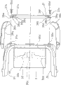
Fig. 5 is the front view of the 3rd cover member.
Fig. 6 is the partial sectional view of fixing after the 3rd cover member.
[description of reference numerals]
3, rotor; 12, pinion; 30, linking part; 31, the 1 rotor arms; 32, the 2 rotor arms; 33, rotor subject; 36a, the 1st cover member; 36b, the 2nd cover member; 37, the 3 cover members; 38a, the 1st fixed support; 38b, the 2nd fixed support; 38c, 38f, protuberance; 38d, 38g, fixed part; 38e, 38h, through hole
Embodiment
[overall structure of spinning-reel and the structure of reel]
As shown in Figure 1 and Figure 2, the spinning-reel adopting in one embodiment of the present invention comprises reel 2, rotor 3 and spool 4.Wherein, at reel 2 upper supports, having can be with respect to the handle 1 of its rotation.Rotor 3 is bearing in the anterior of reel 2 and can rotates with respect to reel 2, and it is used for the fishing line of reeling on spool 4.Spool 4 is arranged on the anterior of rotor 3 and can moves forward and backward with respect to rotor 3, and fishing line is wound onto on the outer peripheral face of this spool 4.In addition, as shown in Figure 1, handle 1 not only can be arranged on the left side of reel 2, also can be arranged on the right side of reel 2.
As shown in Figure 1 and Figure 2, handle 1 comprises: handle rocking arm 8, and extend with the direction that Handle axis 8a intersects on its top edge that is arranged on Handle axis 8a (Fig. 2); Handle axle (not shown), it is fixed on the top of handle rocking arm 8; Handle 9, it is arranged in handle axle and can rotates to it.
[structure of reel]
As shown in Figure 1 and Figure 2, reel 2 comprises: fishing line reel wheel body 2a, and it has opening and is made by for example aluminium alloy; Cover 2b, its can and fishing line reel wheel body 2a between carry out dismounting and be used for sealing this opening, by for example aluminium alloy, made; Fishing rod mount pad 2c, it extends to front upper place sideling from fishing line reel wheel body 2a.The inside of fishing line reel wheel body 2a has the space with this open communication, in this space, is provided with: rotor driving mechanism 5, and it links and in the rotation of handle 1, makes rotor 3 rotate; Swing mechanism 6, it is used for making spool 4 to move forward and backward, so that fishing line is wound on spool 4 equably.On fishing line reel wheel body 2a and cover 2b, not only form flange part 2e, on fishing line reel wheel body 2a, be also formed with the outstanding cylindrical portion 2f forward from flange part 2e.Reel 2 rear portions are covered by protecting component 17.
[structure of rotor driving mechanism]
As shown in Figure 2, rotor driving mechanism 5 comprises: main gear shaft 10, and it is used for fixing the Handle axis 8a in handle 1; Master gear 11, it rotates together with main gear shaft 10; Pinion 12, itself and master gear 11 mesh.Main gear shaft 10 is tubular axles of being made by for example stainless steel, and its two ends are being supported by the bearing (not shown) being arranged on fishing line reel wheel body 2a and cover 2b.On 2 inner peripheral surfaces of main gear shaft 10, be formed with the internal thread part that direction of rotation is different (not shown).
Pinion 12 is that its anterior 12a runs through the central part of rotor 3 with the cartridge that for example stainless steel is made, and this pinion 12 is fixed on rotor 3 and can be rotated together with rotor 3 by nut 13.By the bearing 14a, the 14b that install in spaced mode on fishing line reel wheel body 2a, support respectively middle part and rearward end on the axial direction of pinion 12, pinion 12 can be rotated in fishing line reel wheel body 2a.
[structure of swing mechanism]
The rear end of spool axle 15 is fixed thereon in the mode that can not rotate with respect to slide block 22.Slide block 22 is arranged on the axis of guide (not shown) on fishing line reel wheel body 2a and that its axis is fore-and-aft direction by two and leads along fore-and-aft direction.Idler gear 23 and pinion 12 engagements.
[structure of rotor]
As shown in Figure 2 to 4, rotor 3 comprises: rotor subject 33, and it links and can rotate together with pinion 12 with pinion 12; Fishing line is led arm 34, and it is arranged on rotor subject 33 in the mode that can swing with respect to rotor subject 33.Rotor subject 33 comprises: tubular linking part 30, and itself and pinion 12 link; The 1st rotor arm 31, the 1st side direction of its rearward end from linking part 30, extend and and linking part 30 between there is certain intervals; The 2nd rotor arm 32, the 2nd side direction of its rearward end from linking part 30, extend and and linking part 30 between have certain intervals, wherein the 1st side and the 2nd side face one another.Rotor subject 33 is made by for example aluminium alloy, and makes through one-body molded processing.
At the middle part of linking part 30, be formed with the 30a of wall portion, at the central portion of the 30a of wall portion, be formed with the 30b of hub portion.Central part at the 30b of hub portion is formed with through hole 30c, and the anterior 12a of pinion 12 and spool axle 15 run through this through hole 30c.In the front portion of the 30a of wall portion, be provided with rotor 3 is fixed on to the nut 13 on pinion 12.At the rear portion of linking part 30, be formed with the depressed part 30d with circular space, the front portion that can take in reel 2 in it.
The 1st rotor arm 31 is outwardly-bent from linking part 30, projection is also forwards extended, and the 1st rotor arm 31 is also crooked along the circumferencial direction expansion of linking part 30 with the part that linking part 30 links.The 2nd rotor arm 32 equally also, projection outwardly-bent from linking part 30 also forwards extends, and the part that itself and linking part 30 link is also expanded and bending along the circumferencial direction of linking part 30.In addition, for alleviating its quality, on the 2nd rotor arm 32, be formed with opening (not shown).In the rear surface of the 1st rotor arm 31 and the 2nd rotor arm 32, be formed with screw 31a, the 32a (Fig. 4) that are used for fixing the 3rd cover member 37 that will mention in the back.
In addition, as shown in Fig. 3, Fig. 4 and Fig. 6, rotor 3 also comprises: the 1st cover member 36a and the 2nd cover member 36b (example of outside mask cover), and it covers respectively the outside of the 1st rotor arm 31 and the 2nd rotor arm 32; The 3rd cover member 37 (example of rear portion cover member), it covers the rearward end of linking part 30.In addition, rotor 3 also comprises that with the 3rd cover member 37 be holistic the 1st fixed support 38a and the 2nd fixed support 38b.
The lateral surface of the 1st cover member 36a is to be crooked and outwardly three-dimension curved surface, and the 1st cover member 36a is fixed on the 1st rotor arm 31 by the screwed part 55a installing from its lateral surface, thereby is fixed on rotor subject 33.The 1st cover member 36a has the three-dimensional bending composition surface 36c that can closely engage with the 3rd cover member 37.Between the 1st cover member 36a and the 1st rotor arm 31, be provided with and lead arm switching mechanism 39.
The lateral surface of the 2nd cover member 36b is to be crooked and outwardly three-dimension curved surface, the 2nd cover member 36b is fixed on the 2nd rotor arm 32 by the screwed part 55b installing from its lateral surface, and the 2nd cover member 36b has the three-dimensional bending composition surface 36d that can closely engage with the 3rd cover member 37.
The 3rd cover member 37 comprises: circular open 37a, and it is formed on the central part of the 3rd cover member 37, and the flange part 2e of reel 2 can be set in it; Composition surface 37b, 37c, it is formed on the both sides of the 3rd cover member 37, and can engage with the 1st cover member 36a and the 2nd cover member 36b respectively.Opening 37a forms can expose the mode of depressed part 30d, and the flange part 2e of reel 2 can be set in depressed part 30d.By two screwed part 55c, 55d that run through fixed support 38a, 38b, the 3rd cover member 37 is fixed on rotor subject 33. Composition surface 37b, 37c three-dimensional bending and closely engage with composition surface 36c, 36d respectively.
The 1st fixed support 38a and the 2nd fixed support 38b are arranged on the place ahead of the 3rd cover member 37, and by the 1st cover member 36a and the 2nd cover member 36b, are covered respectively.Fixed support 38a, 38b give prominence to and are integrally formed with it to the place ahead of the 3rd cover member 37.Specifically, they are forwards outstanding from composition surface (example of edge) 37b, the 37c of the 3rd cover member 37, and are integrally formed with the 3rd cover member 37.In order to fix the 3rd cover member 37 and to be provided with the 1st fixed support 38a in the 1st rotor arm 31 1 sides.
As shown in Figure 5, while observing from rear, the 1st fixed support 38a is arranged on from 37b center, composition surface (through the center line Y of the center of rotation X of rotor 3) position that (among Fig. 5, due to from forward observation, institute thinks left side) is offset to the right.So do is to produce and interfere in order to avoid it and to lead between arm switching mechanism 39.As shown in Fig. 3~5, the 1st fixed support 38a comprises: protuberance 38c, and it is outstanding that its composition surface 37b from the 3rd cover member 37 is forwards tabular; Fixed part 38d, its jag from protuberance 38c extends laterally along radial direction, is formed with the through hole 38e that can be run through by screwed part 55c on fixed part 38d.Therefore, fixed part 38d is arranged on the place ahead of composition surface 37b.
While observing from rear, the 2nd fixed support 38b is arranged on from 37c center, composition surface (through the center line Y of the center of rotation X of rotor 3) position that (among Fig. 5, due to from forward observation, institute thinks right side) is offset to the left.So do is in order to adjust the rotary balance between itself and the 1st fixed support 38a.The 2nd fixed support 38b comprises: protuberance 38f, and it is outstanding that its composition surface 37c from the 3rd cover member 37 is forwards tabular; Fixed part 38g, its jag from protuberance 38f extends laterally along radial direction, is formed with the through hole 38h that can be run through by screwed part 55d on fixed part 38g.Therefore, fixed part 38g is also arranged on the place ahead of composition surface 37c.
When assemble rotor 3, first install and lead after arm switching mechanism 39 and fishing line lead arm 34, as shown in Figure 6, then by screwed part 55c, 55d, the 3rd cover member 37 is fixed on the rear surface of rotor subject 33.Now, the threaded portion of screwed part 55c is inserted to the through hole 38e of the 1st fixed support 38a, and screwed part 55c is screwed in screw 31a.Then the threaded portion of screwed part 55d is inserted to the through hole 38h of the 2nd fixed support 38b, and screwed part 55d is screwed in screw 31b.So far, the operation of fixing the 3rd cover member 37 is just through with.
Next, the 1st cover member 36a and the 2nd cover member 36b are respectively fixed on the 1st rotor arm 31 and the 2nd rotor arm 32.Because the 1st cover member 36a and the 2nd cover member 36b form can cover the mode of the 1st fixed support 38a and the 2nd fixed support 38b, so, after installing the 1st cover member 36a and the 2nd cover member 36b, the 1st fixed support 38a and the 2nd fixed support 38b and be arranged on screwed part 55c, 55d above them can be covered and can be to exposing outside.
[fishing line is led the structure of arm]
As shown in Figure 2, as the fishing line of line guide for fishing mechanism, lead the top that arm 34 is arranged on the 1st rotor arm 31 and the 2nd rotor arm 32, and can between unwrapping wire state and take-state, swing.Fishing line is led arm 34 and is led arm switching mechanism 39 (Fig. 3) to unwrapping wire state or the take-state application of force.
As shown in Figure 3, fishing line is led arm 34 and is comprised: the 1st leads arm support unit 40, and its outer circumferential side that is arranged on the top of the 1st rotor arm 31 also can swing on the 1st rotor arm 31; The 2nd leads arm support unit 42, and its outer circumferential side that is arranged on the top of the 2nd rotor arm 32 also can swing on the 2nd rotor arm 32; Line roller 41, it is arranged on the 1st top of leading arm support unit 40.In addition, fishing line is led arm 34 and is also comprised: fixed axis 43, and it is fixed on the 1st and leads the top of arm support unit 40, and by the 1st, is led 40 supportings of arm support unit with the form of cantilever; Fixed axis cover 44, it is arranged on top one side of fixed axis 43; Lead arm 45, it is led arm support unit 42 by fixed axis cover 44 and the 2nd and is connected.In addition, fishing line is led arm 34 and is also comprised the fixed structure 46 containing retaining thread parts 56, and these retaining thread parts 56 are used for that fixed axis 43 is fixed on to the 1st and lead on arm support unit 40.
The 1st to lead arm support unit 40 are parts of being made by aluminium alloy, and its lateral surface is coated with through for example chromium plating and processes and the metal film that forms, makes its surperficial hardening, so can prevent that its lateral surface is because contacting and cause scuffing with fishing line owing to processing by chromium plating.The 1st leads arm support unit 40 is arranged on the 1st rotor arm 31 by construction bolt 49, and can swing with respect to the 1st rotor arm 31.On the 1st top of leading arm support unit 40, be provided with set bolt 56, by this set bolt 56, fix fixed axis 43.
Fixed axis cover 44 and shape roughly take the shape of the letter U and crooked leading arm 45 through for example forging processing and being integrally formed.Fixed axis cover 44 can be arranged on fixed axis 43.The top of leading arm 45 adopts the mode of riveted joint to be fixed on the 2nd and leads on arm support unit 42.
[leading the structure of arm switching mechanism]
As shown in Figure 3, leading arm switching mechanism 39 is arranged between the 1st rotor arm 31 and the 1st cover member 36a.Leading that arm switching mechanism 39 links in the rotation of rotor 3 and make fishing line lead arm 34 is line guide for fishing state from unwrapping wire state restoration, and under two states, keeps its residing state separately.
Leading arm switching mechanism 39 comprises: toggle spring mechanism 39a, and it is arranged on the 1st and leads on arm support unit 40, and can lead 40 swings of arm support unit with respect to the 1st; Moving-member 39b, it is arranged on the 1st rotor arm 31, and can roughly along fore-and-aft direction, move; Switching part (not shown), it not only can contact moving-member 39b, can also be installed to flange part 2e above or pull down from it.Toggle spring mechanism 39a leads arm 34 to unwrapping wire state or the line guide for fishing state application of force to fishing line.When fishing line is led arm 34 in unwrapping wire state, and rotor 3 is when the direction of coiling fishing line is rotated, and moving-member 39b can contact switching part and make fishing line lead arm 34 to line guide for fishing state one side shifting.
[structure of anti-inversion organization]
As shown in Figure 2, in the inside of the linking part 30 of rotor 3, be provided with the anti-inversion organization 50 of forbidding rotor 3 reversings.Anti-inversion organization 50 comprises: roller type the 1st one-way clutch 51, and its inner ring can rotate; Pawl type the 2nd one-way clutch 52, it is arranged on the outer circumferential side of pinion 12.The 1st one-way clutch 51 comprises: outer ring 51a, and it is arranged in the cylindrical portion 2f of fishing line reel wheel body 2a, and can not rotate with respect to cylindrical portion 2f; Inner ring 51b, it is arranged on pinion 12 and can rotates with respect to pinion 12; Roller 51c, its between outer ring 51a and inner ring 51b, when inner ring 51b is when unwinding direction rotates, this roller 51c can wedge between outer ring 51a and inner ring 51b.Because the 1st one-way clutch 51 has adopted roller type structure, so restrict rotor 3 reversings immediately.But, because the transmitting torque allowable of roller type the 1st one-way clutch 51 is relatively little, so in present embodiment, be also provided with pawl type the 2nd one-way clutch 52 that transmitting torque allowable is larger.
As shown in Figure 2, the 2nd one-way clutch 52 arrange from the 12c of tooth portion of pinion 12 close to.The 2nd one-way clutch 52 is the one-way clutchs that help out, on rotor 3, have compared with the strong moment of torsion along unwinding direction effect, make that the 1st one-way clutch 51 skids, during rotor 3 reversing, the 2nd one-way clutch 52 just can be worked.
Described anti-inversion organization 50 always works when unwinding direction reverses at rotor 3, and it does not allow rotor 3 to reverse.
[structure of spool]
As shown in Figure 2, spool 4 is arranged between the 1st rotor arm 31 and the 2nd rotor arm 32 of rotor 3, and it is bearing in the top of spool axle 15 and can rotates with respect to spool axle 15.Spool 4 comprises: bobbin main part 4a, and it is made and is arranged on spool axle 15 by for example aluminium alloy, the fishing line of can reeling in its periphery; Lordosis edge 4b, rear flange part 4c, the former is formed on the front end of bobbin main part 4a and is structure as a whole with this bobbin main part 4a, and the latter is formed on the rear end of bobbin main part 4a and is structure as a whole with this bobbin main part 4a; Skirt section 4d, it is tubular and is integrally formed on rear flange part 4c.Has taken in the inside of spool 4: unload force mechanisms 60, it applies the brake force that sets so that the rotation of spool 4 is braked to spool 4; Unload power sound generating mechanism 85, it sounds when unloading force mechanisms 60 work.
[unloading the structure of force mechanisms]
As shown in Figure 2, unload force mechanisms 60 be to spool 4 apply brake force so that spool 4 to the braked mechanism of the rotation of unwinding direction.Unloading force mechanisms 60 comprises: knob assembly 70, available hand operated knob assembly 70 and adjusting unloading the brake force of force mechanisms 60; Forward and backward friction part 71,72, they are urged to spool 4 one sides because of the effect of knob assembly 70, and because acting on the difference of the thrust size on knob assembly 70, produce the brake force of different sizes.Knob assembly 70 is arranged on the front portion of spool 4, and front friction part 71 is arranged on the inside of the bobbin main part 4a of spool 4, and rear friction part 72 is arranged on the rear of rear flange part 4c.
[operation of fishing line reel and action]
When jettisoninging bait, to unwrapping wire state turnover fishing line, lead arm 34, and make the 1st to lead arm support unit 40 and the 2nd and lead arm support unit 42 and swing.Now, fisherman can limit hauls fishing line limit with the forefinger of possessing the hand of fishing rod and outwards throws pole, and fishing line is taken advantage of a situation and dished out under the effect of angling group gravity.If in this state to take-up direction turning handle 1, rotor 3 can rotate to take-up direction under the effect of rotor driving mechanism 5 so, and fishing line leads under arm 34 leads arm switching mechanism 39 effect at fishing line and be restored to take-up position, fishing line moves and is winding to spool 4 to line roller 41 from leading arm 45.Now, owing to considering the rotary balance of the 1st fixed support 38a and the 2nd fixed support 38b, it is arranged, so can prevent that the situation of the rotary balance variation that causes because of the 1st fixed support 38a and the 2nd fixed support 38b from occurring.
[architectural feature]
(A) for fixing the 3rd cover member 37 that covers the rear surface of rotor subject 33 is provided with the 1st fixed support 38a and the 2nd fixed support 38b, and they are covered by the 1st cover member 36a and the 2nd cover member 36b respectively, therefore, not only the lateral surface of rotor subject 33 can be covered by the 1st cover member 36a and the 2nd cover member 36b, and the 1st fixed support 38a and the 2nd fixed support 38b are because of can be to exposing outside by its covering yet.Here, owing to using by the 1st fixed support 38a and the 2nd fixed support 38b of the 1st cover member 36a and the 2nd cover member 36b covering, and by screwed part 55c, 55d, the 1st fixed support 38a and the 2nd fixed support 38b are fixed on rotor subject 33, so, the fixed part branch of the 3rd cover member 37 is covered by the 1st cover member 36a and the 2nd cover member 36b, thereby screwed part 55c, 55d also can be covered, the head of screwed part 55c, 55d just can not be to exposing outside thus.
(B) the 1st fixed support 38a and the 2nd fixed support 38b comprise respectively: protuberance 38c, 38f, and it is outstanding that they are forwards tabular from composition surface 37b, the 37c of the 3rd cover member 37 respectively; Fixed part 38d, 38g, they extend along radial direction laterally from the jag of protuberance 38c, 38f respectively, and are formed with through hole 38e, the 38h that can be run through by screwed part 55c, 55d.
So, owing to running through the fixed part 38d, the 38g that extend laterally along radial direction by screwed part 55c, 55d, fix the 3rd cover member 37, so can enough this fixed part 38d, 38g the 3rd cover member 37 be positioned on fore-and-aft direction.Therefore, even if the 1st cover member 36a, the 2nd cover member 36b of the method for processing by mould molding processing and the bonding part of the 3rd cover member 37, the 1 cover member 36a, the 2nd cover member 36b and the 3rd cover member 37 are also easy to engage.
(C) the 1st fixed support 38a is arranged in its relative both sides with the 2nd fixed support 38b to clip the mode of the center line Y of the 3rd cover member 37, and this center line Y is through the center of rotation X of rotor 3.
In this case, because the 1st fixed support 38a is arranged in its relative both sides with the 2nd fixed support 38b to clip the mode of the center line of rear side cover member, so through hole can be formed to clip the mode of center line.Therefore, even due at least the arranging that fishing line is led mechanism's parts such as arm switching mechanism on one of them of 2 rotor arms and cannot form through hole on center line time, also can prevent from arranging the 1st fixed support 38a and the 2nd fixed support 38b and the situation of the rotary balance variation brought occurs on the eccentric position that clips center line Y.
[other embodiments]
An embodiment of the invention have more than been described, but the present invention is not limited to above-mentioned embodiment, within not departing from the scope of inventive concept, can does various modification to it.
(a) in the above-described embodiment, the 1st fixed support 38a, the 2nd fixed support 38b and the 3rd cover member 37 are integrally formed, but they also can separately form.
(b) in the above-described embodiment, both on the 1st rotor arm 31, be provided with the 1st cover member 36a as outside mask cover, on the 2nd rotor arm 32, be provided with again the 2nd cover member 36b as outside mask cover, but also can be only outside mask cover be set on rotor arm one of therein.Now, for not possessing the rotor arm of outside mask cover, for example, also can carry out elasticity locking to rear side cover member.
Claims (3)
1. the rotor of a spinning-reel, be used on the spinning-reel of unwrapping wire forward, it links and can rotate together with described pinion with pinion, it is characterized in that, described rotor comprises rotor subject, outside mask cover, rear side cover member and fixed support, described rotor subject comprises: the linking part of tubular, and itself and described pinion link and can therewith rotate, the 1st rotor arm, the 1st side direction of its rearward end from described linking part, extend and and this linking part between there is certain intervals, the 2nd rotor arm, the 2nd side direction of its rearward end from described linking part, extend and and this linking part between there is certain intervals, described outside mask cover covers at least outside of one of them of described the 1st rotor arm and the 2nd rotor arm, described rear side cover member is combined with the rearward end of described outside mask cover and is covered the rearward end of described linking part, described fixed support is at least one, it is arranged on the place ahead of described rear side cover member in the mode being covered by described outside mask cover, it is fixed to described rear side cover member on described rotor subject by screwed part, described fixed support comprises: protuberance, it is outstanding that its edge from described rear side cover member is forwards tabular, fixed part, its jag from described protuberance extends laterally along radial direction, and be formed with the through hole that can be run through by described screwed part, described fixed part is arranged on the place ahead of the edge of described rear side cover member, after installing described outside mask cover, described fixed support and to be arranged on this screwed part above fixed support covered and can be to exposing outside.
2. the rotor of spinning-reel according to claim 1, is characterized in that,
Described outside mask cover comprises: the 1st cover member, and it covers the outside of described the 1st rotor arm; The 2nd cover member, it covers the outside of described the 2nd rotor arm, and described fixed support comprises: the 1st fixed support, its fixed part is arranged on the place ahead of the bonding part of described the 1st cover member and described rear side cover member; The 2nd fixed support, its fixed part is arranged on the place ahead of the bonding part of described the 2nd cover member and described rear side cover member.
3. the rotor of spinning-reel according to claim 2, is characterized in that,
Described the 1st fixed support and the 2nd fixed support are arranged on described rear side cover member, and they are to clip the center line of the center of rotation by described rotor and relative mode is positioned at the both sides of described rear side cover member.
Applications Claiming Priority (2)
| Application Number | Priority Date | Filing Date | Title |
|---|---|---|---|
| JP2009016292A JP5199904B2 (en) | 2009-01-28 | 2009-01-28 | Spinning reel rotor |
| JP2009-016292 | 2009-01-28 |
Publications (2)
| Publication Number | Publication Date |
|---|---|
| CN101785446A CN101785446A (en) | 2010-07-28 |
| CN101785446B true CN101785446B (en) | 2014-03-19 |
Family
ID=42353378
Family Applications (1)
| Application Number | Title | Priority Date | Filing Date |
|---|---|---|---|
| CN201010102775.1A Active CN101785446B (en) | 2009-01-28 | 2010-01-25 | Rotor for spinning reel |
Country Status (9)
| Country | Link |
|---|---|
| US (1) | US7798437B2 (en) |
| EP (1) | EP2248418B1 (en) |
| JP (1) | JP5199904B2 (en) |
| KR (1) | KR101628022B1 (en) |
| CN (1) | CN101785446B (en) |
| AT (1) | ATE537701T1 (en) |
| MY (1) | MY144873A (en) |
| SG (1) | SG163479A1 (en) |
| TW (1) | TWI473564B (en) |
Families Citing this family (7)
| Publication number | Priority date | Publication date | Assignee | Title |
|---|---|---|---|---|
| US9055735B2 (en) * | 2012-06-07 | 2015-06-16 | Shimano Inc. | Spinning reel and spinning-reel reel unit |
| US10010061B2 (en) | 2015-03-18 | 2018-07-03 | Shimano Inc. | Spinning reel |
| JP6688603B2 (en) * | 2015-12-14 | 2020-04-28 | 株式会社シマノ | Spinning reel rotor and spinning reel |
| JP6871141B2 (en) * | 2017-12-12 | 2021-05-12 | グローブライド株式会社 | Spinning reel for fishing |
| JP7143116B2 (en) * | 2018-05-18 | 2022-09-28 | シマノコンポネンツ マレーシア エスディーエヌ.ビーエッチディー. | spinning reel |
| JP7212516B2 (en) * | 2018-12-27 | 2023-01-25 | 株式会社シマノ | spinning reel |
| CN111903630A (en) * | 2019-05-08 | 2020-11-10 | 广州辉悦贸易有限公司 | Fishing reel |
Citations (3)
| Publication number | Priority date | Publication date | Assignee | Title |
|---|---|---|---|---|
| EP1095561A1 (en) * | 1999-10-27 | 2001-05-02 | Shimano Inc. | Rotor for spinning reels |
| CN1352877A (en) * | 2000-11-13 | 2002-06-12 | 株式会社岛野 | Rotor of rotating wire winder |
| EP1260138A1 (en) * | 2001-05-22 | 2002-11-27 | Shimano Inc. | Spinning reel rotor |
Family Cites Families (8)
| Publication number | Priority date | Publication date | Assignee | Title |
|---|---|---|---|---|
| JP3504520B2 (en) * | 1998-11-25 | 2004-03-08 | ダイワ精工株式会社 | Spinning reel for fishing |
| JP2002335822A (en) * | 2001-05-22 | 2002-11-26 | Shimano Inc | Rotor of spinning reel |
| JP3593516B2 (en) | 2001-10-19 | 2004-11-24 | 株式会社シマノ | Spinning reel rotor |
| JP2003225038A (en) * | 2002-02-04 | 2003-08-12 | Shimano Inc | Rotor for spinning reel |
| JP3905068B2 (en) * | 2003-07-25 | 2007-04-18 | 株式会社シマノ | Spinning reel rotor |
| JP4804314B2 (en) * | 2006-11-20 | 2011-11-02 | 株式会社シマノ | Spinning reel rotor |
| JP4891850B2 (en) | 2007-07-09 | 2012-03-07 | 株式会社オートネットワーク技術研究所 | Joint connector |
| JP4963289B2 (en) * | 2007-12-18 | 2012-06-27 | 株式会社シマノ | Spinning reel rotor |
-
2009
- 2009-01-28 JP JP2009016292A patent/JP5199904B2/en active Active
- 2009-12-18 US US12/641,335 patent/US7798437B2/en active Active
-
2010
- 2010-01-04 SG SG201000030-5A patent/SG163479A1/en unknown
- 2010-01-05 MY MYPI2010000019A patent/MY144873A/en unknown
- 2010-01-12 KR KR1020100002555A patent/KR101628022B1/en active IP Right Grant
- 2010-01-13 TW TW99100814A patent/TWI473564B/en active
- 2010-01-20 AT AT10151208T patent/ATE537701T1/en active
- 2010-01-20 EP EP10151208A patent/EP2248418B1/en active Active
- 2010-01-25 CN CN201010102775.1A patent/CN101785446B/en active Active
Patent Citations (3)
| Publication number | Priority date | Publication date | Assignee | Title |
|---|---|---|---|---|
| EP1095561A1 (en) * | 1999-10-27 | 2001-05-02 | Shimano Inc. | Rotor for spinning reels |
| CN1352877A (en) * | 2000-11-13 | 2002-06-12 | 株式会社岛野 | Rotor of rotating wire winder |
| EP1260138A1 (en) * | 2001-05-22 | 2002-11-27 | Shimano Inc. | Spinning reel rotor |
Also Published As
| Publication number | Publication date |
|---|---|
| ATE537701T1 (en) | 2012-01-15 |
| US20100187345A1 (en) | 2010-07-29 |
| JP5199904B2 (en) | 2013-05-15 |
| TW201116210A (en) | 2011-05-16 |
| EP2248418B1 (en) | 2011-12-21 |
| SG163479A1 (en) | 2010-08-30 |
| EP2248418A1 (en) | 2010-11-10 |
| US7798437B2 (en) | 2010-09-21 |
| MY144873A (en) | 2011-11-30 |
| JP2010172226A (en) | 2010-08-12 |
| CN101785446A (en) | 2010-07-28 |
| KR20100087631A (en) | 2010-08-05 |
| KR101628022B1 (en) | 2016-06-08 |
| TWI473564B (en) | 2015-02-21 |
Similar Documents
| Publication | Publication Date | Title |
|---|---|---|
| CN101785446B (en) | Rotor for spinning reel | |
| CN101467521B (en) | Spool of fishing reel | |
| CN102396435B (en) | Dual-bearing reel drag sound producing device | |
| TW518203B (en) | Spool of spinning reel | |
| TWI361663B (en) | Spinning reel drag mechanism | |
| TWI410212B (en) | The connecting member of the reel for fishing | |
| TW398954B (en) | A master gear for a spinning reel | |
| CN104041469A (en) | Ratchet wheel for fishing reel | |
| KR101195809B1 (en) | Spinning-reel sounding mechanism | |
| CN101133729A (en) | Spinning reel | |
| TWI641317B (en) | Fishing reel, spool of fishing reel, and spool shaft of fishing reel | |
| CN104509501A (en) | Spool unit for fishing reel | |
| CN104509504A (en) | Dual-bearing reel | |
| TW201340866A (en) | Spinning reel fishing line guide mechanism and spinning reel | |
| CN101904324B (en) | Spinning reel drag knob | |
| JP2010172226A5 (en) | ||
| TWI276401B (en) | Reel unit for spinning reel | |
| JP2002218871A (en) | Structure for fastening component for fishing tackle | |
| JP3854823B2 (en) | Spinning reel spool | |
| CN1386410A (en) | Rotor for rotary reel | |
| KR102054240B1 (en) | Spinning reel and spool for spinning reel | |
| KR20040019250A (en) | Spinning-reel sounding mechanism | |
| JP2000093054A (en) | Reel for fishing | |
| JP2001269094A (en) | Spool of spinning reel | |
| JP4625591B2 (en) | Spinning reel spool |
Legal Events
| Date | Code | Title | Description |
|---|---|---|---|
| C06 | Publication | ||
| PB01 | Publication | ||
| C10 | Entry into substantive examination | ||
| SE01 | Entry into force of request for substantive examination | ||
| GR01 | Patent grant | ||
| GR01 | Patent grant |