EP1259348B1 - Systeme et procede de moulage de pieces coulees de metal a grain fin et de grande purete - Google Patents
Systeme et procede de moulage de pieces coulees de metal a grain fin et de grande purete Download PDFInfo
- Publication number
- EP1259348B1 EP1259348B1 EP00919900A EP00919900A EP1259348B1 EP 1259348 B1 EP1259348 B1 EP 1259348B1 EP 00919900 A EP00919900 A EP 00919900A EP 00919900 A EP00919900 A EP 00919900A EP 1259348 B1 EP1259348 B1 EP 1259348B1
- Authority
- EP
- European Patent Office
- Prior art keywords
- casting
- metal
- droplets
- liquidus
- molten
- Prior art date
- Legal status (The legal status is an assumption and is not a legal conclusion. Google has not performed a legal analysis and makes no representation as to the accuracy of the status listed.)
- Expired - Lifetime
Links
Images


Classifications
-
- B—PERFORMING OPERATIONS; TRANSPORTING
- B22—CASTING; POWDER METALLURGY
- B22F—WORKING METALLIC POWDER; MANUFACTURE OF ARTICLES FROM METALLIC POWDER; MAKING METALLIC POWDER; APPARATUS OR DEVICES SPECIALLY ADAPTED FOR METALLIC POWDER
- B22F3/00—Manufacture of workpieces or articles from metallic powder characterised by the manner of compacting or sintering; Apparatus specially adapted therefor ; Presses and furnaces
- B22F3/115—Manufacture of workpieces or articles from metallic powder characterised by the manner of compacting or sintering; Apparatus specially adapted therefor ; Presses and furnaces by spraying molten metal, i.e. spray sintering, spray casting
-
- B—PERFORMING OPERATIONS; TRANSPORTING
- B22—CASTING; POWDER METALLURGY
- B22D—CASTING OF METALS; CASTING OF OTHER SUBSTANCES BY THE SAME PROCESSES OR DEVICES
- B22D23/00—Casting processes not provided for in groups B22D1/00 - B22D21/00
- B22D23/06—Melting-down metal, e.g. metal particles, in the mould
- B22D23/10—Electroslag casting
-
- C—CHEMISTRY; METALLURGY
- C22—METALLURGY; FERROUS OR NON-FERROUS ALLOYS; TREATMENT OF ALLOYS OR NON-FERROUS METALS
- C22B—PRODUCTION AND REFINING OF METALS; PRETREATMENT OF RAW MATERIALS
- C22B9/00—General processes of refining or remelting of metals; Apparatus for electroslag or arc remelting of metals
- C22B9/16—Remelting metals
- C22B9/18—Electroslag remelting
-
- C—CHEMISTRY; METALLURGY
- C23—COATING METALLIC MATERIAL; COATING MATERIAL WITH METALLIC MATERIAL; CHEMICAL SURFACE TREATMENT; DIFFUSION TREATMENT OF METALLIC MATERIAL; COATING BY VACUUM EVAPORATION, BY SPUTTERING, BY ION IMPLANTATION OR BY CHEMICAL VAPOUR DEPOSITION, IN GENERAL; INHIBITING CORROSION OF METALLIC MATERIAL OR INCRUSTATION IN GENERAL
- C23C—COATING METALLIC MATERIAL; COATING MATERIAL WITH METALLIC MATERIAL; SURFACE TREATMENT OF METALLIC MATERIAL BY DIFFUSION INTO THE SURFACE, BY CHEMICAL CONVERSION OR SUBSTITUTION; COATING BY VACUUM EVAPORATION, BY SPUTTERING, BY ION IMPLANTATION OR BY CHEMICAL VAPOUR DEPOSITION, IN GENERAL
- C23C4/00—Coating by spraying the coating material in the molten state, e.g. by flame, plasma or electric discharge
- C23C4/12—Coating by spraying the coating material in the molten state, e.g. by flame, plasma or electric discharge characterised by the method of spraying
- C23C4/123—Spraying molten metal
-
- B—PERFORMING OPERATIONS; TRANSPORTING
- B22—CASTING; POWDER METALLURGY
- B22F—WORKING METALLIC POWDER; MANUFACTURE OF ARTICLES FROM METALLIC POWDER; MAKING METALLIC POWDER; APPARATUS OR DEVICES SPECIALLY ADAPTED FOR METALLIC POWDER
- B22F9/00—Making metallic powder or suspensions thereof
- B22F9/02—Making metallic powder or suspensions thereof using physical processes
- B22F9/06—Making metallic powder or suspensions thereof using physical processes starting from liquid material
- B22F9/08—Making metallic powder or suspensions thereof using physical processes starting from liquid material by casting, e.g. through sieves or in water, by atomising or spraying
- B22F9/082—Making metallic powder or suspensions thereof using physical processes starting from liquid material by casting, e.g. through sieves or in water, by atomising or spraying atomising using a fluid
- B22F2009/0848—Melting process before atomisation
- B22F2009/0852—Electroslag melting
-
- B—PERFORMING OPERATIONS; TRANSPORTING
- B22—CASTING; POWDER METALLURGY
- B22F—WORKING METALLIC POWDER; MANUFACTURE OF ARTICLES FROM METALLIC POWDER; MAKING METALLIC POWDER; APPARATUS OR DEVICES SPECIALLY ADAPTED FOR METALLIC POWDER
- B22F9/00—Making metallic powder or suspensions thereof
- B22F9/02—Making metallic powder or suspensions thereof using physical processes
- B22F9/06—Making metallic powder or suspensions thereof using physical processes starting from liquid material
- B22F9/08—Making metallic powder or suspensions thereof using physical processes starting from liquid material by casting, e.g. through sieves or in water, by atomising or spraying
- B22F9/082—Making metallic powder or suspensions thereof using physical processes starting from liquid material by casting, e.g. through sieves or in water, by atomising or spraying atomising using a fluid
- B22F2009/0848—Melting process before atomisation
- B22F2009/0856—Skull melting
-
- B—PERFORMING OPERATIONS; TRANSPORTING
- B22—CASTING; POWDER METALLURGY
- B22F—WORKING METALLIC POWDER; MANUFACTURE OF ARTICLES FROM METALLIC POWDER; MAKING METALLIC POWDER; APPARATUS OR DEVICES SPECIALLY ADAPTED FOR METALLIC POWDER
- B22F2998/00—Supplementary information concerning processes or compositions relating to powder metallurgy
Definitions
- the invention relates to casting systems and methods with cooling of the casting.
- the invention related to clean metal nucleated casting systems and methods with cooling of the casting.
- Metals such as iron- (Fe), nickel- (Ni), titanium- (Ti), and cobalt- (Co) based alloys, are often used in turbine component applications, in which fine-grained microstructures, homogeneity, and essentially defect-free compositions are desired. Problems in superalloy castings and ingots are undesirable as the costs associated with superalloy formation are high, and results of these problems, especially in ingots formed into turbine components are undesirable. Conventional systems for producing castings have attempted to reduce the amount of impurities, contaminants, and other constituents, which may produce undesirable consequences in an component made from the casting.
- One such problem that may often arise with respect to superalloys comprises controlling the grain size and other microstructure of the refined metals.
- refining processing involves multiple steps, such as sequential heating and melting, forming, cooling, and reheating of the large bodies of metal because the volume of the metal being refined is generally of at least about 2250 kg (5,000 pounds) and can be greater than about 16000 kg (35,000 pounds).
- problems of alloy or ingredient segregation also occur as processing is performed on large bodies of metal.
- a lengthy and expensive sequence of processing steps is selected to overcome the above-mentioned difficulties, which arise through the use of bulk processing and refining operations of metals.
- a known such sequence used in industry involves vacuum induction melting; followed by electroslag refining (such as disclosed in US Patent Nos. 5,160,532; 5,310,165; 5,325,906; 5,332,197; 5,348,566; 5,366,206; 5,472,177; 5,480,097; 5,769,151; 5,809,057; and 5,810,066, all of which are assigned to the Assignee of the instant invention); followed, in turn, by vacuum arc refining (VAR) and followed, again in turn, by mechanical working through forging and drawing to achieve a fine microstructure.
- VAR vacuum arc refining
- the metal produced by such a sequence is highly useful and the metal product itself is quite valuable, the processing is quite expensive and time-consuming. Further, the yield from such a sequence can be low, which results in increased costs. Further, the processing sequence does not ensure defect-free metals, and ultrasonic inspection is generally employed to identify and reject components that include such defects, which results in increased costs.
- a conventional electroslag refining process typically uses a refining vessel that contains a slag-refining layer floating on a layer of molten refined metal.
- An ingot of unrefined metal is generally used as a consumable electrode and is lowered into the vessel to make contact with the molten electroslag layer.
- An electric current is passed through the slag layer to the ingot and causes surface melting at the interface between the ingot and the slag layer.
- oxide inclusions or impurities are exposed to the slag and removed at the contact point between the ingot and the slag.
- Droplets of refined metal are formed, and these droplets pass through the slag and are collected in a pool of molten refined metal beneath the slag.
- the refined metal may then be formed into a casting, such as, but not limited to, an ingot (collectively referred to hereinafter as "castings").
- the above-discussed electroslag refining and the resultant casting may be dependent on a relationship between the individual process parameters, such as, but not limited to, an intensity of the refining current, specific heat input, and melting rate.
- This relationship involves undesirable interdependence between the rate of electroslag refining of the metal, metal ingot and casting temperatures, and rate at which a refined molten metal casting is cooled from its liquidus state to its solid state, all of which may result in poor metallurgical structure in the resultant casting.
- electroslag refining may not provide for the controlling of an amount and depth of the liquidus portion in a casting.
- a reduced solidification rate may result in the casting having properties and characteristics that are not desirable.
- the undesirable characteristics may include inhomogeneous microstructure, defects including (but not limited to) impurities, voids and inclusions, segregations, and a porous (non-dense) material resulting from entrapped air due to slow solidification.
- a deep melt pool causes a varied degree of ingredient macrosegregation in the metal that leads to a less desirable microstructure, such as a microstructure that is not a fine-grained microstructure, or segregation of the elemental species so as to form an inhomogeneous structure.
- a subsequent processing operation has been proposed in combination with the electroslag refining process to overcome this deep melt pool problem. This subsequent processing may be vacuum arc remelting (VAR).
- Vacuum arc remelting is initiated when an ingot is processed by vacuum arc steps to produce a relatively shallow melt pool, whereby an improved microstructure, which may also possess a lower hydrogen content, is produced.
- the resulting ingot is then mechanically worked to yield a metal stock having a desirable fine-grained microstructure.
- Such mechanical working may involve a combination of steps of forging, drawing, and heat treatment. This thermo-mechanical processing requires large, expensive equipment, as well as costly amounts of energy input.
- the metal casting produced by the casting system according to the invention comprises a fine-grain, homogeneous microstructure that is essentially oxide- and sulfide-free, segregation defect free, and essentially free of voids caused by air entrapped during solidification of the metal from a liquidus state to a solid state.
- the casting system comprises an electroslag refining system; a nucleated casting system; and a cooling system that cools the metal casting so as to cool a liquidus portion of the metal casting.
- the metal casting is cooled in a manner sufficient to provide a microstructure that comprises a fine-grain, homogeneous microstructure that is essentially oxide- and sulfide-free, segregation defect free, and essentially free of voids caused by air entrapped during solidification from a liquidus state to a solid state.
- the method according to the invention comprises forming a source of clean refined metal that has oxides and sulfides refined out by electroslag refining; forming the article by nucleated casting; and cooling a liquidus portion of the metal casting by supplying coolant to the casting.
- the step of cooling is sufficient to cool the metal casting in a manner sufficient to provide a microstructure that comprises a fine-grain, homogeneous microstructure that is essentially oxide- and sulfide-free, segregation defect free, and essentially free of voids caused by air entrapped during solidification from a liquidus state to a solid state.
- U.S. Patent No. 3,752,215 (“the '215 patent”) describes a continuous casting apparatus for shaped metal bodies.
- the '215 patent describes a slag bath formed in the upper portion of a molding cavity formed between casting molds. Molten metal is poured into the molding cavity through the slag bath. Next, viscous slag films are formed by the slag bath between the casting molds and the metal. The metal is then cooled through the slag films.
- Casting systems and methods with cooling of the casting can be provided on casting systems, such as, but not limited to, vertical casting systems and casting systems that include vertical casting with electroslag refining and cold-induction guides.
- the systems and methods with cooling of the casting will be described hereinafter with respect to vertical casting with electroslag refining and cold-induction guides as illustrated in Figs. 1-4.
- this description is not intended to limit the invention in any way, and the scope of the invention is defined in the claims.
- the casting systems and methods with cooling of the casting can produce a casting (in which the term “casting” includes any casting, such as a perform, ingot, and the like) with essentially oxide free and impurity free characteristics, and being dense and essentially non-porous.
- the term “essentially free” means that any constituents in the material do not adversely influence the material, for example its strength and related characteristics, and the term “essentially non-porous” means that the material is dense, amounts of entrapped air is minimal, and does not adversely influence the material.
- the clean-liquid metal source for the casting systems and methods with cooling of the casting can comprise an electroslag refining apparatus that provides a clean liquid metal, because of the electroslag refining steps.
- the electroslag refining apparatus can comprise an electroslag refining system in cooperation with a cold-induction guide (CIG), as set forth in the above-mentioned patents to the Assignee of the instant invention.
- CCG cold-induction guide
- a nucleated casting system may permit a plurality of molten metal droplets to be formed and pass through a cooling zone, which is formed with a length sufficient to allow up to about 30 volume percent of each of the droplets to solidify on average.
- the droplets are then received by a mold and solidification of the metal droplets is completed in the mold.
- the droplets retain liquid characteristics and readily flow within the mold, when less than about 30 volume percent of the droplets is solid.
- the casting systems and methods with cooling of the casting to provide coolant to cool the casting.
- the coolant is supplied directly on a solidified portion of the casting to cool the liquidus portion of the casting, such as in a withdrawal mold.
- the supply of coolant will reduce the temperature of the casting.
- the reduced temperature will create a temperature gradient in the casting with the lower temperature being disposed at the location where the coolant is applied.
- the temperature gradient will then draw heat away from the liquidus (higher temperature) portion of the casting.
- the drawing away of heat will expedite the cooling and enhanced solidification of the liquidus upper portion of the casting.
- the expedited cooling and enhanced solidification of the liquidus upper portion will reduce the amount of entrapped air in the casting, thus forming a dense casting that contains few entrapped air voids.
- the expedited cooling and enhanced solidification rates of the liquidus upper portion will enhance the microstructural characteristics of the casting by reducing the grain size, providing an essentially segregation free microstructure, and a homogeneous microstructure.
- the cooling of the casting can produce a casting possessing a homogeneous, fine-grained microstructure for many metals and alloys, including, but not limited to, nickel- (Ni) and cobalt- (Co) based superalloys, iron- (Fe), titanium- (Ti), alloys, which are often used in turbine component applications.
- the castings formed by the cooling of the casting, as embodied by the invention can be converted into a final article, a billet, or directly forged with reduced processing and heat treatment steps, due to their homogeneous, fine-grained microstructure.
- the cooling of the casting can be used to produce high quality forgings that can be used in many applications, such as but not limited to rotating equipment applications, such as, but not limited to, disks, rotors, blades, vanes, wheel, buckets, rings; shafts, wheels, and other such elements, and other turbine component applications.
- rotating equipment applications such as, but not limited to, disks, rotors, blades, vanes, wheel, buckets, rings; shafts, wheels, and other such elements, and other turbine component applications.
- turbine components formed from castings however, this is merely exemplary of the applications within the scope of the invention.
- Fig. I illustrates a semi-schematic, part-sectional, elevational view of an exemplary casting system 3 with cooling of a casting by a cooling system 300, as embodied by the invention.
- Figures 2-4 illustrate details of features illustrated in Fig. 1. The cooling of the casting with the electroslag refining system 1 will be initially described followed by a description of the nucleated casting system 2 to facilitate the understanding of the invention.
- Figure 1 is a schematic illustration of a casting system 3 with cooling of the casting, as embodied by the invention, for producing a casting 145.
- the metal for the clean metal nucleated casting system 3 and its associated clean metal nucleated casting processes is provided by an electroslag refining system 1.
- the clean metal is fed to a nucleated casting system 2.
- the electroslag refining system 1 and nucleated casting system 2 cooperate to form a clean metal nucleated casting system 3, which in turn forms the cooling of the casting, as embodied by the invention.
- the electroslag refining system 1 introduces a consumable electrode 24 of metal to be refined directly into an electroslag refining system 1, and refines the consumable electrode 24 to produce a clean, refined metal melt 46 (hereafter "clean metal").
- the source of metal for the electroslag refining system 1 as a consumable electrode 24 is merely exemplary, and the scope of the invention comprises, but is not limited to, the source metal comprising an ingot, melt of metal, powder metal, and combinations thereof.
- the description of the invention will refer to a consumable electrode, however this is merely exemplary and is not intended to limit the invention in any manner.
- the clean metal 46 is received and retained within a cold hearth structure 40 that is mounted below the electroslag refining apparatus 1.
- the clean metal 46 is dispensed from the cold hearth structure 40 through a cold finger orifice structure 80 that is mounted and disposed below the cold hearth structure 40.
- the electroslag refining system 1 can provide essentially steady state operation in supplying clean metal 46 if the rate of electroslag refining of metal and rate of delivery of refined metal to a cold hearth structure 40 approximates the rate at which molten metal 46 is drained from the cold hearth structure 40 through an orifice 81 of the cold finger orifice structure 80.
- the clean metal nucleated casting process can operate continuously for an extended period of time and, accordingly, can process a large bulk of metal.
- the clean metal nucleated casting process can be operated intermittently by intermittent operation of one or more of the features of the clean metal nucleated casting system 3.
- the clean metal 46 exits the electroslag refining system 1 through the cold finger orifice structure 80, it enters into the nucleated casting system 2. Then, the clean metal 46 can be further processed to produce a relatively large ingot of refined metal. Alternatively, the clean metal 46 may be processed through to produce smaller castings, ingots, articles, or formed into continuous cast articles.
- the clean metal nucleated casting process effectively eliminates many of the processing operations, such as those described above that, until now, have been necessary in order to produce a metal casting having a desired set of material characteristics and properties.
- a vertical motion control apparatus 10 is schematically illustrated.
- the vertical motion control apparatus 10 comprises a box 12 mounted to a vertical support 14 that includes a motive device (not illustrated), such as but not limited to a motor or other mechanism.
- the motive device is adapted to impart rotary motion to a screw member 16.
- An ingot support structure 20 comprises a member, such as but not limited to a member 22, that is threadedly engaged at one end to the screw member 16.
- the member 22 supports the consumable electrode 24 at its other end by an appropriate connection, such as, but not limited to, a bolt 26.
- An electroslag refining structure 30 comprises a reservoir 32 that is cooled by an appropriate coolant, such as, but not limited to, water.
- the reservoir 32 comprises a molten slag 34, in which an excess of the slag 34 is illustrated as the solid slag granules 36.
- the slag composition used in the clean metal nucleated casting process will vary with the metal being processed.
- a slag skull 75 may be formed along inside surfaces of an inner wall 82 of reservoir 32, due to the cooling influence of the coolant flowing against the outside of inner wall 82, as described hereinafter.
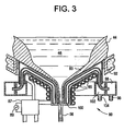
- a cold hearth structure 40 (Figs. 1-3) is mounted below the electroslag refining structure 30.
- the cold hearth structure 40 comprises a hearth 42, which is cooled by an appropriate coolant, such as water.
- the hearth 42 contains a skull 44 of solidified refined metal and a body of refined liquid metal 46.
- the reservoir 32 may be formed integrally with the hearth 42. Alternatively, the reservoir 32 and hearth 42 may be formed as separate units, which are connected to form the electroslag refining system 1.
- a bottom orifice 81 of the electroslag refining system 1 is provided in the cold finger orifice structure 80, which is described with reference to Figs. 3 and 4.
- a clean metal 46 which is refined by the electroslag refining system I so as to be essentially free of oxides, sulfides, and other impurities, can traverse the electroslag refining system 1 and flow out of the orifice 81 of the cold finger orifice structure 80.
- a power supply structure 70 can supply electric refining current to the electroslag refining system 1.
- the power supply structure 70 can comprise an electric power supply and control mechanism 74.
- An electrical conductor 76 that is able to carry current to the member 22 and, in turn, carry current to the consumable electrode 24 connects the power supply structure 70 to the member 22.
- a conductor 78 is connected to the reservoir 32 to complete a circuit for the power supply structure 70 of the electroslag refining system 1.
- FIG 2 is a detailed part-sectional illustration of the electroslag refining structure 30 and the cold hearth structure 40 in which the electroslag refining structure 30 defines an upper portion of the reservoir 32 and the cold hearth structure 40 defines a lower portion 42 of the reservoir 32.
- the reservoir 32 generally comprises a double-walled reservoir, which includes an inner wall 82 and outer wall 84.
- a coolant 86 such as but not limited to water, is provided between the inner wall 82 and outer wall 84.
- the coolant 86 can flow to and through a flow channel, which is defined between the inner wall 82 and outer wall 84 from a supply 98 (Fig. 3) and through conventional inlets and outlets (not illustrated in the figures).
- the cooling water 86 that cools the wall 82 of the cold hearth structure 40 provides cooling to the electroslag refining structure 30 and the cold hearth structure 40 to cause the skull 44 to form on the inner surface of the cold hearth structure 40.
- the coolant 86 is not essential for operation of the electroslag refining system 1, clean metal nucleated casting system 3, or electroslag refining structure 30. Cooling may insure that the liquid metal 46 does not contact and attack the inner wall 82, which may cause some dissolution from the wall 82 and contaminate the liquid metal 46.
- the cold hearth structure 40 also comprises an outer wall 88, which may include flanged tubular sections, 90 and 92. Two flanged tubular sections 90 and 92 are illustrated in the bottom portion of Fig. 2.
- the outer wall 88 cooperates with the nucleated casting system 2 to form a controlled atmosphere environment 140, which is described hereinafter.
- the cold hearth structure 40 comprises a cold finger orifice structure 80 that is shown detail Figs. 3 and 4.
- the cold finger orifice structure 80 is illustrated in Fig. 3 in relation to the cold hearth structure 40 and a stream 56 of liquid melt 46 that exits the cold hearth structure 40 through the cold finger orifice structure 80.
- the cold finger orifice structure 80 is illustrated (Figs. 2 and 3) in structural cooperation with the solid metal skull 44 and liquid metal 46.
- Figure 4 illustrates the cold finger orifice structure 80 without the liquid metal or solid metal skull, so details of the cold finger orifice structure 80 are illustrated.
- the cold finger orifice structure 80 comprises the orifice 81 from which processed molten metal 46 is able to flow in the form of a stream 56.
- the cold finger orifice structure 80 is connected to the cold hearth structure 40 and the cold hearth structure 30. Therefore, the cold hearth structure 40 allows processed and generally impurity-free alloy to form the skulls 44 and 83 by contacting walls of the cold hearth structure 40.
- the skulls 44 and 83 thus act as a container for the molten metal 46.
- the skull 83 (Fig. 3), which is formed at the cold finger orifice structure 80, is controllable in terms of its thickness, and is typically formed with a smaller thickness than the skull 44.
- the thicker skull 44 contacts the cold hearth structure 40 and the thinner skull 83 contacts the cold finger orifice structure 80, and the skulls 44 and 83 are in contact with each other to form an essentially continuous skull.
- a controlled amount of heat may be provided to the skull 83 and thermally transmitted to the liquid metal body 46.
- the heat is provided from induction heating coils 85 that are disposed around the cold hearth structure.
- An induction-heating coil 85 can comprise a cooled induction-heating coil, by flow of an appropriate coolant, such as water, into it from a supply 87.
- Induction heating power is supplied from a power source 89, which is schematically illustrated in Fig. 3.
- the construction of the cold finger orifice structure 80 permits heating by induction energy to penetrate the cold finger orifice structure 80 and heat the liquid metal 46 and skull 83, and maintain the orifice 81 open so that the stream 56 may flow out of the orifice 81.
- the orifice may be closed by solidification of the stream 56 of liquid metal 46 if heating power is not applied to the cold finger orifice structure 80.
- the heating is dependent on each of the fingers of the cold finger orifice structure 80 being insulated from the adjoining fingers, for example being insulated by an air or gas gap or by a suitable insulating material.
- the cold finger orifice structure 80 is illustrated in Fig. 4, with both skulls 44 and 83 and the molten metal 46 are omitted for clarity.
- An individual cold finger 97 is separated from each adjoining finger, such as finger 92, by a gap 94.
- the gap 94 may be provided and filled with an insulating material, such as, but not limited to, a ceramic material or insulating gas.
- the molten metal 46 (not illustrated) that is disposed within the cold finger orifice structure 80 does not leak out through the gaps, because the skull 83 creates a bridge over the cold fingers and prevents passage of liquid metal 46 therethrough.
- Each gap extends to the bottom of the cold finger orifice structure 80, as illustrated in Fig.
- the gaps can be provided with a width in a range from about of 0,5 mm (20 mils) to about 1.3 mm (50 mils), which is sufficient to provide an insulated separation of respective adjacent fingers.
- the individual fingers may be provided with a coolant, such as water, by passing coolant into a conduit 96 from a suitable coolant source (not shown).
- the coolant is then passed around and through a manifold 98 to the individual cooling tubes, such as cooling tube 100. Coolant that exits the cooling tube 100 flows between an outside surface of the cooling tube 100 and an inside surface of a finger.
- the coolant is then collected in a manifold 102, and passed out of the cold finger orifice structure 80 through a water outlet tube 104.
- This individual cold finger water supply tube arrangement allows for cooling of the cold finger orifice structure 80 as a whole.
- the amount of heating or cooling that is provided through the cold finger orifice structure 80 to the skulls 44 and 83, as well as to the liquid metal 46, can be controlled to control the passage of liquid metal 46 through the orifice 81 as a stream 56.
- the controlled heating or cooling is done by controlling the amount of current and coolant that pass in the induction coils 85 to and through the cold finger orifice structure 80.
- the controlled heating or cooling can increase or decrease the thickness of the skulls 44 and 83, and to open or close the orifice 81, or to reduce or increase the passage of the stream 56 through the orifice 81.
- More or less liquid metal 46 can pass through the cold finger orifice structure 80 into the orifice 81 to define the stream 56 by increasing or decreasing the thickness of the skulls 44 and 83:
- the flow of the stream 56 can be maintained at a desirable balance, by controlling coolant water and heating current and power to and through the induction heating coil 85 to maintain the orifice 81 at a set passage size along with controlling the thickness of the skulls 44 and 83.
- the electroslag refining system 1 of the clean metal nucleated casting system 3 can refine ingots that can include defects and impurities or that can be relatively refined.
- a consumable electrode 24 is melted by the electroslag refining system 1.
- the consumable electrode 24 is mounted in the electroslag refining system 1 in contact with molten slag in the electroslag refining system.
- Electrical power is provided to the electroslag refining system and ingot. The power causes melting of the ingot at a surface where it contacts the molten slag and the formation of molten drops of metal. The molten drops to fall through the molten slag.
- the drops are collected after they pass through the molten slag as a body of refined liquid metal in the cold hearth structure 40 below the electroslag refining structure 30.
- Oxides, sulfides, contaminants, and other impurities that originate in the consumable electrode 24 are removed as the droplets form on the surface of the ingot and pass through the molten slag.
- the molten drops are drained from the electroslag refining system 1 at the orifice 81 in the cold finger orifice structure 80 as a stream 56.
- the stream 56 that exits the electroslag refining system 1 of the clean metal nucleated casting system 3 that forms articles comprises a refined melt that is essentially free of oxides, sulfides, contaminants, and other impurities.
- the rate at which the metal stream 56 exits the cold finger orifice structure 80 can further be controlled by controlling a hydrostatic head of liquid metal 46 above the orifice 81.
- the liquid metal 46 and slag 44 and 83 that extend above the orifice 81 of the cold finger orifice structure 80 define the hydrostatic head. If a clean metal nucleated casting system 3 with an electroslag refining system 1 is operated with a given constant hydrostatic head and a constant sized orifice 81, an essentially constant flow rate of liquid metal can be established.
- the melt rate is generally equal to the removal rate from the clean metal nucleated casting system 3, as a stream 56.
- the current applied to the clean metal nucleated casting system 3 can be adjusted to provide more or less liquid metal 46 and slag 44 and 83 above the orifice 81.
- the amount of liquid metal 46 and slag 44 and 83 above the orifice 81 is determined by the power that melts the ingot, and the cooling of the electroslag refining system 1, which create the skulls. By adjusting the applied current, flow through the orifice 81 can be controlled.
- the contact of the consumable electrode. 24 with an upper surface of the molten slag 34 can be maintained in order to establish a steady state of operation 1.
- a rate of consumable electrode 24 descent into the melt 46 can be adjusted to ensure that contact of the consumable electrode 24 with the upper surface of the molten slag 34 is maintained for the steady state operation.
- a steady-state discharge from the stream 56 can be maintained in the clean metal nucleated casting system 3.
- the stream 56 of metal that is formed in the electroslag refining system 1 of the clean metal nucleated casting system 3 exits electroslag refining system 1 and is fed to a nucleated casting system 2.
- the nucleated casting system 2 is schematically illustrated in Fig. I in cooperation with the electroslag refining system 1.
- the nucleated casting system 2 that acts to form articles comprises a disruption site 134 that is positioned to receive the stream 56 from the electroslag refining system 1 of the clean metal nucleated casting system 3.
- the disruption site 134 converts the stream 56 into a plurality of molten metal droplets 138.
- the stream 56 is fed to disruption site 134 in a controlled atmosphere environment 140 that is sufficient to prevent substantial and undesired oxidation of the droplets 138.
- the controlled atmosphere environment 140 may include any gas or combination of gases, which do not react with the metal of the stream 56. For example, if the stream 56 comprises aluminum or magnesium, the controlled atmosphere environment 140 presents an environment that prevents the droplets 138 from becoming a fire hazard.
- any noble gas or nitrogen is suitable for use in the controlled atmosphere environment 140 because these gases are generally non-reactive with most metals and alloys within the scope of the invention.
- nitrogen which is a low-cost gas, can be in the controlled atmosphere environment 140, except for metals and alloys that are prone to excessive nitriding.
- the controlled atmosphere environment 140 may comprise nitrogen, argon, and mixtures thereof.
- the metal comprises nickel or steel, the controlled atmosphere environment 140 can comprises nitrogen or argon, or mixtures thereof.
- the disruption site 134 can comprise any suitable device for converting the stream 56 into droplets 138.
- the disruption site 134 can comprise a gas atomizer, which circumscribes the stream 56 with one or more jets 142.
- the flow of gas from the jets 142 that impinge on the stream can be controlled, so the size and velocity of the droplets 138 can be controlled.
- Another atomizing device within the scope of the invention, includes a high pressure atomizing gas in the form of a stream of the gas, which is used to form the controlled atmosphere environment 140.
- the stream of controlled atmosphere environment 140 gas can impinge the metal stream 56 to convert the metal stream 56 into droplets 138.
- Other exemplary types of stream disruption include magneto-hydrodynamic atomization, in which the stream 56 flows through a narrow gap between two electrodes that are connected to a DC power supply with a magnet perpendicular to the electric field, and mechanical-type stream disruption devices.
- the droplets 138 are broadcast downward (Fig. 1) from the disruption site 134 to form a generally diverging cone shape.
- the droplets 138 traverse a cooling zone 144, which is defined by the distance between the disruption site 134 and the upper surface 150 of the metal casting that is supported by the mold 146.
- the cooling zone 144 length is sufficient to solidify a volume fraction portion of a droplet by the time the droplet traverses the cooling zone 144 and impacts the upper surface 150 of the metal casting.
- the portion of the droplet 138 that solidifies (hereinafter referred to as the "solid volume fraction portion”) is sufficient to inhibit coarse dendritic growth in the mold 146 up to a viscosity inflection point at which liquid flow characteristics in the mold are essentially lost.
- the partially molten/partially solidified metal droplets collect in mold 146.
- the mold may comprise a retractable base 246, which can be withdrawn from sidewalls of the mold 146 so as to define a withdraw mold.
- the retractable base can be connected to a shaft 241 to move base away from the sidewalls in the direction of arrow 242. Further, the shaft 241 may rotate the retractable base 246 in the direction of arrow 243 to provide most portions of the mold to a cooling system, which is described hereinafter.
- the semisolid droplets behave like a liquid if the solid volume fraction portion is less than a viscosity inflection point, and the semisolid droplets exhibit sufficient fluidity to conform to the shape of the mold.
- an upper solid volume fraction portion limit that defines a viscosity inflection point is less than about 40% by volume.
- An exemplary solid volume fraction portion is in a range from about 5% to about 40%, and a solid volume fraction portion in a range from about 15% to about 30% by volume does not adversely influence the viscosity inflection point.
- the spray of droplets 138 creates a liquidus, upper portion 148 disposed proximate the surface of the casting 145 in the mold 146.
- the depth of the liquidus, upper portion 148 is dependent on cooling of the liquidus portion, the solidification rate thereof, and various clean metal nucleated casting system 3 factors, such as, but not limited to, the atomization gas velocity, droplet velocity, the cooling zone 144 length, the stream temperature, and droplet size.
- the liquidus, upper portion 148 can be created with a depth in the mold 146 in a range from about 0.13-25.4 mm (0.005 inches to about 1.0 inches).
- An exemplary liquidus, upper portion 148 within the scope of invention comprises a depth in a range from about 6.2-12.7 mm (0.25 to about 0.50 inches) in the mold.
- the liquidus, upper portion 148 in the mold 146 should not be greater that a region of the casting, where the metal exhibits predominantly liquid characteristics.
- expedited solidification of the liquidus portion minimizes gas entrapment and resultant pores in the casting.
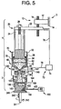
- the casting system 3 of Fig. 5 (and Fig. 6 as described hereinafter) comprises features as described above.
- the additional features of these figures will be described hereinafter, while the description of the common features is set forth above.
- a cooling system 300 (Fig. 1), as embodied by the invention, can extract heat from the casting 145.
- the cooling system 300 comprises a source of coolant 301.
- the coolant can comprise any appropriate coolant, such as, but not limited to, an inert cooling gas that will not react with the material of the casting.
- Exemplary cooling gases within the scope of the invention comprise argon, nitrogen, and helium.
- the coolant is directed onto the casting 145 itself as the casting 145 is being withdrawn from the mold 146.
- the coolant exits the cooling system 300 in the form of a spray 303 after passing through a coolant conduit 302 from the coolant supply 301.
- the coolant system 400 comprises a source of coolant 401.
- the coolant can comprise any appropriate coolant, such as, but not limited to, an inert cooling gas that will not react with the material of the casting.
- Exemplary cooling gases within the scope of the invention comprise argon, nitrogen, and helium.
- the coolant is directed onto the casting 145 itself as the casting 145 is being withdrawn from the mold 146.
- the coolant exits the cooling system 400 in the form of a spray 403 after passing through a coolant conduit 402 from the coolant supply 401.
- Each respective cooling system, 300 and 400 may be used separately. Alternatively, if both cooling systems, 300 and 400, are provided, both cooling systems 300 and 400 may be used together for cooling the casting 145 and mold 146. Thus, the cooling of the liquidus portion of the casting 145 is enhanced.
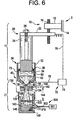
- a casting system with cooling of the casting may comprise a cooling system 500 that provides coolant to the casting 145 leaving a unitary, non-withdrawal type mold 146, as illustrated in Fig. 6.
- the coolant system 500 comprises a source of coolant 501.
- the coolant can comprise any appropriate coolant, such as, but not limited to, an inert cooling gas that will not react with the material of the casting.
- Exemplary cooling gases within the scope of the invention comprise argon, nitrogen, and helium.
- the coolant is directed onto the casting 145 itself through at least one aperture 510 that is formed in the mold 146.
- the figure illustrates a plurality of holes, however this illustration is merely exemplary of the invention.
- the coolant thus exits the cooling system 500 in the form of a spray 503 after passing through a coolant conduit 502 from the coolant supply 501, and impinges onto the casting 145 after passing through the apertures 510.
- the apertures 510 may take any appropriate shape and size that are sufficient to allow passage of the coolant to the casting 145.
- Each above-described cooling system provides cooling of the liquidus upper portion 148 of the casting 145 by thermal conduction.
- the cooling systems 400 and 500 also provide cooling of the liquidus portion of the casting 145 by thermal conduction through the casting 145 and through the walls of the mold 146.
- the liquidus, upper portion 148 can also reduce a thermal gradient in the casting 145 by its inherent turbulent nature.
- the mold 146 can be formed of any suitable material for casting applications, such as but not limited to, graphite, cast iron, and copper.
- Graphite is a suitable mold 146 material since it is relatively easy to machine and exhibits satisfactory thermal conductivity for heat removal via the cooling systems, as embodied by the invention.
- At least one of the disruption site 134 or the mold 146 may be mounted on a moveable support and separated at a fixed rate to maintain a constant cooling zone 144 dimension.
- Baffles 152 (Fig.
- the baffles 152 can prevent oxidation of the partially molten metal droplets 138 and conserve the controlled atmosphere environment gas 140.
- Heat that is extracted from the casting 145 completes the solidification process of the liquidus upper portion 148 of the casting 145 to form solidified castings for further use.
- Sufficient nuclei are formed in casting 145 produced so that upon solidification, a fine equiaxed microstructure 149 can be formed in the casting 145.
- the casting system 3 inhibits undesirable dendritic growth, reduces solidification shrinkage porosity of the formed casting and article, and reduces hot tearing both during casting and during subsequent hot working of the casting and article. Further, the clean metal nucleated casting system 3 produces a uniform, equiaxed structure in the article which is a result of the minimal distortion of the mold during casting, the controlled transfer of heat during solidification of the casting in the mold, and controlled nucleation. The clean metal nucleated casting system 3 enhances ductility and fracture toughness of the article compared to conventionally castings.
- a casting system for example in Figs. 1-6, which comprises an electroslag refining system as a source of liquid metal, a nucleated casting system, and a cooling system 300; 400; 500.
- the scope of the invention further comprises use of cooling systems, as embodied by the invention, with a casting system that comprises a nucleated casting system with any appropriate source of liquid metal, as illustrated in Fig. 7.
- the casting system 710 in Fig. 7 comprises a nucleated casting system 2, which is similar to the nucleated casting system in Figs. 1-6.
- the nucleated casting system 2 of Fig. 7 is illustrated with a withdrawal mold 146, however, any appropriate mold, such as the mold illustrated in Fig. 6, is within the scope of the invention.
- the nucleated casting system 2 comprises a disruption site 134 that is positioned to receive a liquid metal stream 712 from any appropriate source 711.
- the disruption site 134 converts the liquid metal stream 712 into a plurality of molten metal droplets 138.
- the stream 712 can be fed to disruption site 134 in a controlled atmosphere environment 140 that is sufficient to prevent substantial and undesired oxidation of the droplets 138.
- the controlled atmosphere environment 140 may include any gas or combination of gases, which do not react with the metal of the stream 712. For example, if the stream 712 comprises aluminum or magnesium, the controlled atmosphere environment 140 presents an environment that prevents the droplets 138 from becoming a fire hazard.
- the disruption site 134 can comprise any suitable device for converting the stream 712 into droplets 138.
- the disruption site 134 can comprise a gas atomizer, which circumscribes the stream 712 with one or more jets 142.
- the flow of gas from the jets 142 that impinge on the stream can be controlled, so the size and velocity of the droplets 138 can be controlled.
- Another atomizing device within the scope of the invention, includes a high pressure atomizing gas in the form of a stream of the gas, which is used to form the controlled atmosphere environment 140.
- the stream of controlled atmosphere environment 140 gas can impinge the metal stream 712 to convert the metal stream 712 into droplets 138.
- Other exemplary types of stream disruption are described above.
- the droplets 138 are broadcast downward (Fig. 1) from the disruption site 134 to form a generally diverging cone shape 130.
- the droplets 138 traverse a cooling zone 144, which is defined by the distance between the disruption site 134 and the upper surface 150 of the metal casting that is supported by the mold 146.
- the cooling zone 144 length is sufficient to solidify a volume fraction portion of a droplet by the time the droplet traverses the cooling zone 144 and impacts the upper surface 150 of the metal casting.
- the partially molten/partially solidified metal droplets (referred to hereinafter as "semisolid droplets") collect in mold 146.
- the mold may comprise a retractable base 246, which can be withdrawn from sidewalls of the mold 146 so as to define a withdraw mold.
- the retractable base can be connected to a shaft 241 to move base away from the sidewalls in the direction of arrow 242. Further, the shaft 241 may rotate the retractable base 246 in the direction of arrow 243 to provide most portions of the mold to a cooling system, which is described hereinafter. Details of the remainder of the nucleated casting system 2 are as set forth in the above description.
- the cooling system 700 can extract heat from the casting 145.
- the cooling system 700 is similar to the cooling system 300 of Fig. 1, and comprises a source of coolant 701.
- the coolant can comprise any appropriate coolant, such as, but not limited to, an inert cooling gas that will not react with the material of the casting.
- Exemplary cooling gases within the scope of the invention comprise argon, nitrogen, and helium.
- the coolant is directed onto the casting 145 itself as the casting 145 is being withdrawn from the mold 146.
- the coolant exits the cooling system 700 in the form of a spray 703 after passing through a coolant conduit 702 from the coolant supply 701. While the above description of a casting system that comprises a nucleated casting system 2 with an appropriate source of liquid metal illustrates a cooling system 700, which is similar to cooling system 300, any of the cooling systems described herein may be utilized herein.
Landscapes
- Engineering & Computer Science (AREA)
- Chemical & Material Sciences (AREA)
- Mechanical Engineering (AREA)
- Organic Chemistry (AREA)
- Materials Engineering (AREA)
- Metallurgy (AREA)
- Manufacturing & Machinery (AREA)
- Physics & Mathematics (AREA)
- Plasma & Fusion (AREA)
- Chemical Kinetics & Catalysis (AREA)
- Manufacture And Refinement Of Metals (AREA)
- Furnace Details (AREA)
- Turbine Rotor Nozzle Sealing (AREA)
- Continuous Casting (AREA)
Claims (5)
- Système de coulée (3) permettant de produire une pièce coulée (145) en métal, laquelle pièce coulée (145) en métal présente une microstructure homogène à grains fins, qui ne comporte pratiquement ni oxydes ni sulfures, est exempte de défauts de ségrégation et ne comporte pratiquement pas de vides qui seraient engendrés par de l'air piégé au cours de la solidification du métal passant d'un état de liquidus à un état solide, lequel système de coulée (3) comporte :et est caractérisé par :un système de refusion sous laitier électroconducteur (1),et un système de coulée nucléée (2),la portion liquidus de la pièce coulée comprenant une partie supérieure liquidus (148), qui est formée par les gouttelettes de métal (138) dans une zone supérieure de la pièce coulée (145), et la fraction solide d'une gouttelette représentant en moyenne, dans cette partie supérieure liquidus (148), moins d'environ 50 % de son volume.un système de refroidissement (300, 400, 500, 700) qui envoie un agent réfrigérant directement sur une portion solidifiée de la pièce coulée (145), afin de refroidir cette pièce coulée en métal d'une manière suffisante pour faire refroidir une portion liquidus de la pièce coulée en métal (145), laquelle pièce coulée en métal (145) est refroidie d'une manière appropriée pour que se forme ladite microstructure homogène à grains fins,un site d'éclatement (134) à la traversée duquel un courant de métal liquide (56) éclate en gouttelettes (138) de métal en fusion,une zone de refroidissement (144) où sont reçues les gouttelettes (138) de métal fondu, lesquelles gouttelettes (138) de métal fondu se solidifient dans cette zone de refroidissement (144) en gouttelettes semi-solides de telle façon que, dans chaque gouttelette semi-solide, il y a une fraction solide qui représente en moyenne à peu près de 5 à 40 % du volume de la gouttelette, et le reste de la gouttelette semi-solide est en fusion,et un moule (146) qui recueille les gouttelettes en une portion liquidus et où ces gouttelettes se solidifient, ce qui donne une pièce dotée de ladite microstructure homogène à grains fins,
- Système de coulée (3) conforme à la revendication 1, dans lequel le système de refusion sous laitier électroconducteur (1) comporte :une structure (30) de refusion sous laitier électroconducteur, adaptée pour recevoir et contenir un laitier de refusion (34) en fusion ;une source de métal (24) à refondre dans la structure (30) de refusion sous laitier électroconducteur ;une masse de laitier (34) en fusion, disposée dans la structure (30) de refusion sous laitier électroconducteur, la source de métal (24) étant placée en contact avec le laitier (34) en fusion ;une alimentation électrique (70), adaptée pour fournir un courant électrique à la source de métal faisant fonction d'électrode (24) et, à travers le laitier fondu (34), à une masse de métal refondu (46) qui se trouve en dessous du laitier (34), dans le but de maintenir en fusion le laitier de refusion et de faire fondre le bout de la source de métal qui est en contact avec le laitier (34) ;un dispositif d'avancement, servant à faire avancer la source de métal (24) pour la garder au contact du laitier en fusion (34), à une vitesse correspondant à celle à laquelle fond la surface de l'électrode (24) qui est en contact avec le laitier, à mesure que se déroule le processus de refusion de celle-ci ;une structure de sole froide (40) placée en dessous de la structure (30) de refusion sous laitier électroconducteur, laquelle structure de sole froide (40) est adaptée pour recevoir et contenir le métal en fusion, refondu sous laitier électroconducteur, et le maintenir en contact avec un fond solide de métal refondu, formé sur les parois du récipient de la sole froide ;une masse de métal refondu (46) en fusion, située dans la structure de sole froide (40) en dessous du laitier (34) en fusion ;une structure (80) d'orifice à doigt froid, placée au-dessous de la sole froide (40) et adaptée pour recevoir et distribuer un courant (56) de métal refondu (46) en fusion, qui a été traité par le système de refusion sous laitier électroconducteur (1) et qui est passé dans la structure de sole froide (40), laquelle structure (80) d'orifice à doigt froid présente un orifice (81) ;et un fond (44, 83) de métal refondu (46) solidifié, en contact avec la structure (40) de sole froide et la structure (80) d'orifice à doigt froid, y compris l'orifice (81).
- Système de coulée (3) conforme à la revendication 1, dans lequel le système de refroidissement (300, 400, 500, 700) comporte :une alimentation (301, 401, 501, 701) en agent réfrigérant et une conduite (301, 401, 501, 701) pour agent réfrigérant, servant à envoyer l'agent réfrigérant directement depuis l'alimentation (301, 401, 501, 701) en agent réfrigérant sur la pièce coulée en métal (145).
- Système de coulée (3) conforme à la revendication 1, dans lequel la pièce coulée (145) contient de l'un au moins des métaux à base de nickel, cobalt, titane ou fer.
- Procédé de coulée permettant de produire une pièce coulée (145) en métal, laquelle pièce coulée (145) en métal présente une microstructure homogène à grains fins, qui ne comporte pratiquement ni oxydes ni sulfures, est exempte de défauts de ségrégation et ne comporte pratiquement pas de vides qui seraient engendrés par de l'air piégé au cours de la solidification du métal passant d'un état de liquidus à un état solide, lequel procédé comporte :et est caractérisé en ce que :le fait de former une source de métal refondu propre (46) d'où les oxydes et les sulfures ont été éliminés par refusion sous laitier électroconducteur (1),et le fait de façonner la pièce par coulée nucléée (2),la portion liquidus de la pièce coulée comprenant une partie supérieure liquidus (148), qui est formée par les gouttelettes de métal (138) dans une zone supérieure de la pièce coulée (145), et la fraction solide d'une gouttelette représentant en moyenne, dans cette partie supérieure liquidus (148), moins d'environ 50 % de son volume.l'on refroidit une portion liquidus de la pièce coulée (145) en métal en envoyant un agent réfrigérant directement sur une portion solidifiée de la pièce coulée (145), afin de refroidir cette pièce coulée en métal d'une manière suffisante pour faire refroidir une portion liquidus de la pièce coulée (145) en métal, laquelle pièce coulée (145) en métal est refroidie d'une manière appropriée pour que se forme ladite microstructure homogène à grains fins,l'on fait en sorte qu'un courant de métal liquide (56) éclate en gouttelettes (138) de métal en fusion, au niveau d'un site d'éclatement (134),l'on reçoit les gouttelettes (138) de métal fondu dans une zone de refroidissement (144), lesquelles gouttelettes (138) de métal fondu se solidifient dans cette zone de refroidissement (144) en gouttelettes semi-solides de telle façon que, dans chaque gouttelette semi-solide, il y a une fraction solide qui représente en moyenne à peu près de 5 à 40 % du volume de la gouttelette, et le reste de la gouttelette semi-solide est en fusion,et l'on recueille les gouttelettes en une portion liquidus dans un moule (146) où ces gouttelettes se solidifient, ce qui donne une pièce dotée de ladite microstructure homogène à grains fins,
Applications Claiming Priority (3)
| Application Number | Priority Date | Filing Date | Title |
|---|---|---|---|
| US511528 | 2000-02-23 | ||
| US09/511,528 US6631753B1 (en) | 1999-02-23 | 2000-02-23 | Clean melt nucleated casting systems and methods with cooling of the casting |
| PCT/US2000/008484 WO2001062419A1 (fr) | 2000-02-23 | 2000-03-29 | Systemes de moulage par coulee nuclee de matiere fondue propre et procedes equipes d'un systeme de refroidissement de la piece moulee |
Publications (2)
| Publication Number | Publication Date |
|---|---|
| EP1259348A1 EP1259348A1 (fr) | 2002-11-27 |
| EP1259348B1 true EP1259348B1 (fr) | 2005-11-16 |
Family
ID=24035274
Family Applications (1)
| Application Number | Title | Priority Date | Filing Date |
|---|---|---|---|
| EP00919900A Expired - Lifetime EP1259348B1 (fr) | 2000-02-23 | 2000-03-29 | Systeme et procede de moulage de pieces coulees de metal a grain fin et de grande purete |
Country Status (7)
| Country | Link |
|---|---|
| US (1) | US6631753B1 (fr) |
| EP (1) | EP1259348B1 (fr) |
| JP (1) | JP2003523829A (fr) |
| KR (1) | KR100718406B1 (fr) |
| AT (1) | ATE309878T1 (fr) |
| DE (1) | DE60024142T2 (fr) |
| WO (1) | WO2001062419A1 (fr) |
Cited By (1)
| Publication number | Priority date | Publication date | Assignee | Title |
|---|---|---|---|---|
| CN101439405B (zh) * | 2008-12-19 | 2012-09-05 | 江苏技术师范学院 | 镁基复合材料和镁基复合材料零件的成形方法 |
Families Citing this family (19)
| Publication number | Priority date | Publication date | Assignee | Title |
|---|---|---|---|---|
| US6496529B1 (en) | 2000-11-15 | 2002-12-17 | Ati Properties, Inc. | Refining and casting apparatus and method |
| US8891583B2 (en) | 2000-11-15 | 2014-11-18 | Ati Properties, Inc. | Refining and casting apparatus and method |
| US7803212B2 (en) | 2005-09-22 | 2010-09-28 | Ati Properties, Inc. | Apparatus and method for clean, rapidly solidified alloys |
| US7803211B2 (en) | 2005-09-22 | 2010-09-28 | Ati Properties, Inc. | Method and apparatus for producing large diameter superalloy ingots |
| US7578960B2 (en) | 2005-09-22 | 2009-08-25 | Ati Properties, Inc. | Apparatus and method for clean, rapidly solidified alloys |
| EP2137329B1 (fr) | 2007-03-30 | 2016-09-28 | ATI Properties LLC | Four de fusion comprenant un émetteur d'électrons de plasma ionique à décharge à fil |
| US8748773B2 (en) | 2007-03-30 | 2014-06-10 | Ati Properties, Inc. | Ion plasma electron emitters for a melting furnace |
| US7798199B2 (en) | 2007-12-04 | 2010-09-21 | Ati Properties, Inc. | Casting apparatus and method |
| US8320427B2 (en) * | 2009-12-16 | 2012-11-27 | General Electric Company | Cold walled induction guide tube |
| US8747956B2 (en) | 2011-08-11 | 2014-06-10 | Ati Properties, Inc. | Processes, systems, and apparatus for forming products from atomized metals and alloys |
| CN102019379B (zh) * | 2010-10-26 | 2012-08-08 | 西峡龙成特种材料有限公司 | 环境伺服式洁净金属铸模 |
| US10082032B2 (en) | 2012-11-06 | 2018-09-25 | Howmet Corporation | Casting method, apparatus, and product |
| CA2896729C (fr) | 2013-03-12 | 2017-10-17 | Novelis Inc. | Distribution de metal fondu intermittent |
| DE102013008396B4 (de) | 2013-05-17 | 2015-04-02 | G. Rau Gmbh & Co. Kg | Verfahren und Vorrichtung zum Umschmelzen und/oder Umschmelzlegieren metallischer Werkstoffe, insbesondere von Nitinol |
| US9894802B2 (en) * | 2014-05-29 | 2018-02-13 | Ge-Hitachi Nuclear Energy Americas Llc | Passive system of powering and cooling with liquid metal and method thereof |
| CN104625064B (zh) * | 2015-01-29 | 2017-04-05 | 天津百恩威新材料科技有限公司 | 喷射成形降温系统及采用该系统降低锭坯温度的方法 |
| US10421161B2 (en) * | 2016-05-06 | 2019-09-24 | Honeywell International Inc. | High quality, void and inclusion free alloy wire |
| WO2018071217A1 (fr) * | 2016-10-10 | 2018-04-19 | Arconic Inc. | Procédé et appareil de coulage d'alliage à haute pression |
| CA3049465C (fr) | 2017-11-15 | 2021-10-12 | Novelis Inc. | Attenuation de depassement ou de deficit de niveau de metal lors d'une transition de demande de debit |
Family Cites Families (15)
| Publication number | Priority date | Publication date | Assignee | Title |
|---|---|---|---|---|
| JPS4937617B1 (fr) * | 1970-11-12 | 1974-10-11 | ||
| IT940586B (it) * | 1971-11-13 | 1973-02-20 | Dalmine Spa | Procedimento perfezionato di cola ta continua di barre metalliche in particolare di acciaio |
| US4494594A (en) * | 1981-09-08 | 1985-01-22 | Amb Technology, Inc. | Spray cooling system for continuous steel casting machine |
| US5247988A (en) * | 1989-12-19 | 1993-09-28 | Kurzinski Cass R | Apparatus and method for continuously casting steel slabs |
| US5160532A (en) | 1991-10-21 | 1992-11-03 | General Electric Company | Direct processing of electroslag refined metal |
| US5310165A (en) | 1992-11-02 | 1994-05-10 | General Electric Company | Atomization of electroslag refined metal |
| US5348566A (en) | 1992-11-02 | 1994-09-20 | General Electric Company | Method and apparatus for flow control in electroslag refining process |
| US5381847A (en) * | 1993-06-10 | 1995-01-17 | Olin Corporation | Vertical casting process |
| US5472177A (en) | 1993-12-17 | 1995-12-05 | General Electric Company | Molten metal spray forming apparatus |
| US5480097A (en) | 1994-03-25 | 1996-01-02 | General Electric Company | Gas atomizer with reduced backflow |
| US5683653A (en) | 1995-10-02 | 1997-11-04 | General Electric Company | Systems for recycling overspray powder during spray forming |
| US5649993A (en) | 1995-10-02 | 1997-07-22 | General Electric Company | Methods of recycling oversray powder during spray forming |
| US5769151A (en) | 1995-12-21 | 1998-06-23 | General Electric Company | Methods for controlling the superheat of the metal exiting the CIG apparatus in an electroslag refining process |
| US5810066A (en) | 1995-12-21 | 1998-09-22 | General Electric Company | Systems and methods for controlling the dimensions of a cold finger apparatus in electroslag refining process |
| US5809057A (en) | 1996-09-11 | 1998-09-15 | General Electric Company | Electroslag apparatus and guide |
-
2000
- 2000-02-23 US US09/511,528 patent/US6631753B1/en not_active Expired - Lifetime
- 2000-03-29 WO PCT/US2000/008484 patent/WO2001062419A1/fr active IP Right Grant
- 2000-03-29 JP JP2001561470A patent/JP2003523829A/ja not_active Ceased
- 2000-03-29 EP EP00919900A patent/EP1259348B1/fr not_active Expired - Lifetime
- 2000-03-29 DE DE60024142T patent/DE60024142T2/de not_active Expired - Lifetime
- 2000-03-29 KR KR1020027010968A patent/KR100718406B1/ko not_active IP Right Cessation
- 2000-03-29 AT AT00919900T patent/ATE309878T1/de not_active IP Right Cessation
Cited By (1)
| Publication number | Priority date | Publication date | Assignee | Title |
|---|---|---|---|---|
| CN101439405B (zh) * | 2008-12-19 | 2012-09-05 | 江苏技术师范学院 | 镁基复合材料和镁基复合材料零件的成形方法 |
Also Published As
| Publication number | Publication date |
|---|---|
| KR100718406B1 (ko) | 2007-05-14 |
| DE60024142T2 (de) | 2006-07-20 |
| DE60024142D1 (de) | 2005-12-22 |
| EP1259348A1 (fr) | 2002-11-27 |
| KR20020086909A (ko) | 2002-11-20 |
| US6631753B1 (en) | 2003-10-14 |
| ATE309878T1 (de) | 2005-12-15 |
| WO2001062419A1 (fr) | 2001-08-30 |
| JP2003523829A (ja) | 2003-08-12 |
Similar Documents
| Publication | Publication Date | Title |
|---|---|---|
| EP1259348B1 (fr) | Systeme et procede de moulage de pieces coulees de metal a grain fin et de grande purete | |
| US6460595B1 (en) | Nucleated casting systems and methods comprising the addition of powders to a casting | |
| RU2280702C2 (ru) | Устройство и способ для рафинирования и литья | |
| US6264717B1 (en) | Clean melt nucleated cast article | |
| US6427752B1 (en) | Casting systems and methods with auxiliary cooling onto a liquidus portion of a casting | |
| JP2004523359A5 (fr) | ||
| EP0907756B1 (fr) | Traitement d'un metal affine par fusion sous laitier electroconducteur | |
| JPH04504981A (ja) | 反応性合金の誘導スカル紡糸 | |
| EP1263996A1 (fr) | Systemes et procedes de moulage par coulee nuclee | |
| KR100718407B1 (ko) | 주조 장치 및 주조 방법 | |
| KR100622733B1 (ko) | 주조 장치 및 주조 방법 |
Legal Events
| Date | Code | Title | Description |
|---|---|---|---|
| PUAI | Public reference made under article 153(3) epc to a published international application that has entered the european phase |
Free format text: ORIGINAL CODE: 0009012 |
|
| 17P | Request for examination filed |
Effective date: 20020923 |
|
| AK | Designated contracting states |
Kind code of ref document: A1 Designated state(s): AT BE CH CY DE DK ES FI FR GB GR IE IT LI LU MC NL PT SE |
|
| 17Q | First examination report despatched |
Effective date: 20030214 |
|
| GRAP | Despatch of communication of intention to grant a patent |
Free format text: ORIGINAL CODE: EPIDOSNIGR1 |
|
| RTI1 | Title (correction) |
Free format text: CASTING SYSTEM AND METHOD FOR FORMING HIGHLY PURE AND FINE GRAIN METAL CASTINGS |
|
| GRAS | Grant fee paid |
Free format text: ORIGINAL CODE: EPIDOSNIGR3 |
|
| GRAA | (expected) grant |
Free format text: ORIGINAL CODE: 0009210 |
|
| AK | Designated contracting states |
Kind code of ref document: B1 Designated state(s): AT BE CH CY DE DK ES FI FR GB GR IE IT LI LU MC NL PT SE |
|
| PG25 | Lapsed in a contracting state [announced via postgrant information from national office to epo] |
Ref country code: NL Free format text: LAPSE BECAUSE OF FAILURE TO SUBMIT A TRANSLATION OF THE DESCRIPTION OR TO PAY THE FEE WITHIN THE PRESCRIBED TIME-LIMIT Effective date: 20051116 Ref country code: AT Free format text: LAPSE BECAUSE OF FAILURE TO SUBMIT A TRANSLATION OF THE DESCRIPTION OR TO PAY THE FEE WITHIN THE PRESCRIBED TIME-LIMIT Effective date: 20051116 Ref country code: FI Free format text: LAPSE BECAUSE OF FAILURE TO SUBMIT A TRANSLATION OF THE DESCRIPTION OR TO PAY THE FEE WITHIN THE PRESCRIBED TIME-LIMIT Effective date: 20051116 Ref country code: BE Free format text: LAPSE BECAUSE OF FAILURE TO SUBMIT A TRANSLATION OF THE DESCRIPTION OR TO PAY THE FEE WITHIN THE PRESCRIBED TIME-LIMIT Effective date: 20051116 |
|
| REG | Reference to a national code |
Ref country code: GB Ref legal event code: FG4D |
|
| REG | Reference to a national code |
Ref country code: CH Ref legal event code: NV Representative=s name: SERVOPATENT GMBH Ref country code: CH Ref legal event code: EP |
|
| REG | Reference to a national code |
Ref country code: IE Ref legal event code: FG4D |
|
| REF | Corresponds to: |
Ref document number: 60024142 Country of ref document: DE Date of ref document: 20051222 Kind code of ref document: P |
|
| PG25 | Lapsed in a contracting state [announced via postgrant information from national office to epo] |
Ref country code: SE Free format text: LAPSE BECAUSE OF FAILURE TO SUBMIT A TRANSLATION OF THE DESCRIPTION OR TO PAY THE FEE WITHIN THE PRESCRIBED TIME-LIMIT Effective date: 20060216 Ref country code: GR Free format text: LAPSE BECAUSE OF FAILURE TO SUBMIT A TRANSLATION OF THE DESCRIPTION OR TO PAY THE FEE WITHIN THE PRESCRIBED TIME-LIMIT Effective date: 20060216 Ref country code: DK Free format text: LAPSE BECAUSE OF FAILURE TO SUBMIT A TRANSLATION OF THE DESCRIPTION OR TO PAY THE FEE WITHIN THE PRESCRIBED TIME-LIMIT Effective date: 20060216 |
|
| PG25 | Lapsed in a contracting state [announced via postgrant information from national office to epo] |
Ref country code: ES Free format text: LAPSE BECAUSE OF FAILURE TO SUBMIT A TRANSLATION OF THE DESCRIPTION OR TO PAY THE FEE WITHIN THE PRESCRIBED TIME-LIMIT Effective date: 20060227 |
|
| PG25 | Lapsed in a contracting state [announced via postgrant information from national office to epo] |
Ref country code: IE Free format text: LAPSE BECAUSE OF NON-PAYMENT OF DUE FEES Effective date: 20060329 |
|
| PG25 | Lapsed in a contracting state [announced via postgrant information from national office to epo] |
Ref country code: LU Free format text: LAPSE BECAUSE OF NON-PAYMENT OF DUE FEES Effective date: 20060331 Ref country code: MC Free format text: LAPSE BECAUSE OF NON-PAYMENT OF DUE FEES Effective date: 20060331 |
|
| PG25 | Lapsed in a contracting state [announced via postgrant information from national office to epo] |
Ref country code: PT Free format text: LAPSE BECAUSE OF FAILURE TO SUBMIT A TRANSLATION OF THE DESCRIPTION OR TO PAY THE FEE WITHIN THE PRESCRIBED TIME-LIMIT Effective date: 20060417 |
|
| NLV1 | Nl: lapsed or annulled due to failure to fulfill the requirements of art. 29p and 29m of the patents act | ||
| ET | Fr: translation filed | ||
| PLBE | No opposition filed within time limit |
Free format text: ORIGINAL CODE: 0009261 |
|
| STAA | Information on the status of an ep patent application or granted ep patent |
Free format text: STATUS: NO OPPOSITION FILED WITHIN TIME LIMIT |
|
| 26N | No opposition filed |
Effective date: 20060817 |
|
| REG | Reference to a national code |
Ref country code: IE Ref legal event code: MM4A |
|
| REG | Reference to a national code |
Ref country code: CH Ref legal event code: PFA Owner name: GENERAL ELECTRIC COMPANY Free format text: GENERAL ELECTRIC COMPANY#1 RIVER ROAD#SCHENECTADY, NY 12345 (US) -TRANSFER TO- GENERAL ELECTRIC COMPANY#1 RIVER ROAD#SCHENECTADY, NY 12345 (US) |
|
| PG25 | Lapsed in a contracting state [announced via postgrant information from national office to epo] |
Ref country code: CY Free format text: LAPSE BECAUSE OF FAILURE TO SUBMIT A TRANSLATION OF THE DESCRIPTION OR TO PAY THE FEE WITHIN THE PRESCRIBED TIME-LIMIT Effective date: 20051116 |
|
| REG | Reference to a national code |
Ref country code: FR Ref legal event code: PLFP Year of fee payment: 17 |
|
| REG | Reference to a national code |
Ref country code: FR Ref legal event code: PLFP Year of fee payment: 18 |
|
| REG | Reference to a national code |
Ref country code: FR Ref legal event code: PLFP Year of fee payment: 19 |
|
| PGFP | Annual fee paid to national office [announced via postgrant information from national office to epo] |
Ref country code: GB Payment date: 20180327 Year of fee payment: 19 Ref country code: CH Payment date: 20180328 Year of fee payment: 19 |
|
| PGFP | Annual fee paid to national office [announced via postgrant information from national office to epo] |
Ref country code: IT Payment date: 20180322 Year of fee payment: 19 Ref country code: FR Payment date: 20180326 Year of fee payment: 19 |
|
| PGFP | Annual fee paid to national office [announced via postgrant information from national office to epo] |
Ref country code: DE Payment date: 20180328 Year of fee payment: 19 |
|
| REG | Reference to a national code |
Ref country code: DE Ref legal event code: R119 Ref document number: 60024142 Country of ref document: DE |
|
| REG | Reference to a national code |
Ref country code: CH Ref legal event code: PL |
|
| GBPC | Gb: european patent ceased through non-payment of renewal fee |
Effective date: 20190329 |
|
| PG25 | Lapsed in a contracting state [announced via postgrant information from national office to epo] |
Ref country code: DE Free format text: LAPSE BECAUSE OF NON-PAYMENT OF DUE FEES Effective date: 20191001 Ref country code: GB Free format text: LAPSE BECAUSE OF NON-PAYMENT OF DUE FEES Effective date: 20190329 Ref country code: LI Free format text: LAPSE BECAUSE OF NON-PAYMENT OF DUE FEES Effective date: 20190331 Ref country code: CH Free format text: LAPSE BECAUSE OF NON-PAYMENT OF DUE FEES Effective date: 20190331 |
|
| PG25 | Lapsed in a contracting state [announced via postgrant information from national office to epo] |
Ref country code: FR Free format text: LAPSE BECAUSE OF NON-PAYMENT OF DUE FEES Effective date: 20190331 Ref country code: IT Free format text: LAPSE BECAUSE OF NON-PAYMENT OF DUE FEES Effective date: 20190329 |