EP1258759A2 - Fiber optic adapter - Google Patents
Fiber optic adapter Download PDFInfo
- Publication number
- EP1258759A2 EP1258759A2 EP02010241A EP02010241A EP1258759A2 EP 1258759 A2 EP1258759 A2 EP 1258759A2 EP 02010241 A EP02010241 A EP 02010241A EP 02010241 A EP02010241 A EP 02010241A EP 1258759 A2 EP1258759 A2 EP 1258759A2
- Authority
- EP
- European Patent Office
- Prior art keywords
- fiber optic
- housing
- post
- panel
- optic adapter
- Prior art date
- Legal status (The legal status is an assumption and is not a legal conclusion. Google has not performed a legal analysis and makes no representation as to the accuracy of the status listed.)
- Ceased
Links
- 239000000835 fiber Substances 0.000 title claims abstract description 82
- 239000004020 conductor Substances 0.000 claims abstract description 16
- 230000008878 coupling Effects 0.000 claims description 6
- 238000010168 coupling process Methods 0.000 claims description 6
- 238000005859 coupling reaction Methods 0.000 claims description 6
- 238000000034 method Methods 0.000 claims description 6
- OKTJSMMVPCPJKN-UHFFFAOYSA-N Carbon Chemical compound [C] OKTJSMMVPCPJKN-UHFFFAOYSA-N 0.000 claims description 4
- PXHVJJICTQNCMI-UHFFFAOYSA-N Nickel Chemical compound [Ni] PXHVJJICTQNCMI-UHFFFAOYSA-N 0.000 claims description 4
- 238000003780 insertion Methods 0.000 claims description 4
- 230000037431 insertion Effects 0.000 claims description 4
- 239000002245 particle Substances 0.000 claims description 4
- HCHKCACWOHOZIP-UHFFFAOYSA-N Zinc Chemical compound [Zn] HCHKCACWOHOZIP-UHFFFAOYSA-N 0.000 claims description 2
- 229910052799 carbon Inorganic materials 0.000 claims description 2
- 229910002804 graphite Inorganic materials 0.000 claims description 2
- 239000010439 graphite Substances 0.000 claims description 2
- 229910052759 nickel Inorganic materials 0.000 claims description 2
- 229920002379 silicone rubber Polymers 0.000 claims description 2
- 229910052725 zinc Inorganic materials 0.000 claims description 2
- 239000011701 zinc Substances 0.000 claims description 2
- 239000011159 matrix material Substances 0.000 claims 1
- 239000000463 material Substances 0.000 description 9
- 230000013011 mating Effects 0.000 description 5
- 239000002184 metal Substances 0.000 description 5
- 229910052751 metal Inorganic materials 0.000 description 5
- 238000004512 die casting Methods 0.000 description 4
- RYGMFSIKBFXOCR-UHFFFAOYSA-N Copper Chemical compound [Cu] RYGMFSIKBFXOCR-UHFFFAOYSA-N 0.000 description 3
- 230000009286 beneficial effect Effects 0.000 description 3
- 230000008901 benefit Effects 0.000 description 3
- 230000005540 biological transmission Effects 0.000 description 3
- 230000006835 compression Effects 0.000 description 3
- 238000007906 compression Methods 0.000 description 3
- 230000005764 inhibitory process Effects 0.000 description 3
- MCMNRKCIXSYSNV-UHFFFAOYSA-N Zirconium dioxide Chemical compound O=[Zr]=O MCMNRKCIXSYSNV-UHFFFAOYSA-N 0.000 description 2
- 239000000853 adhesive Substances 0.000 description 2
- 230000001070 adhesive effect Effects 0.000 description 2
- 230000004888 barrier function Effects 0.000 description 2
- 238000004891 communication Methods 0.000 description 2
- 238000004519 manufacturing process Methods 0.000 description 2
- 239000013307 optical fiber Substances 0.000 description 2
- 230000008569 process Effects 0.000 description 2
- 229910000906 Bronze Inorganic materials 0.000 description 1
- OAICVXFJPJFONN-UHFFFAOYSA-N Phosphorus Chemical compound [P] OAICVXFJPJFONN-UHFFFAOYSA-N 0.000 description 1
- 206010057430 Retinal injury Diseases 0.000 description 1
- 229910000779 Zamak 3 Inorganic materials 0.000 description 1
- 229910000785 Zamak 7 Inorganic materials 0.000 description 1
- 238000013459 approach Methods 0.000 description 1
- 230000000903 blocking effect Effects 0.000 description 1
- 239000010974 bronze Substances 0.000 description 1
- 238000005266 casting Methods 0.000 description 1
- 230000015556 catabolic process Effects 0.000 description 1
- 239000000919 ceramic Substances 0.000 description 1
- 229910052802 copper Inorganic materials 0.000 description 1
- 239000010949 copper Substances 0.000 description 1
- KUNSUQLRTQLHQQ-UHFFFAOYSA-N copper tin Chemical compound [Cu].[Sn] KUNSUQLRTQLHQQ-UHFFFAOYSA-N 0.000 description 1
- 238000006731 degradation reaction Methods 0.000 description 1
- 239000013536 elastomeric material Substances 0.000 description 1
- 238000005516 engineering process Methods 0.000 description 1
- 231100000040 eye damage Toxicity 0.000 description 1
- 238000007667 floating Methods 0.000 description 1
- 239000011521 glass Substances 0.000 description 1
- 230000007257 malfunction Effects 0.000 description 1
- 230000007246 mechanism Effects 0.000 description 1
- 230000004048 modification Effects 0.000 description 1
- 238000012986 modification Methods 0.000 description 1
- 230000000717 retained effect Effects 0.000 description 1
- 210000001525 retina Anatomy 0.000 description 1
- 230000008054 signal transmission Effects 0.000 description 1
- 229920001169 thermoplastic Polymers 0.000 description 1
- 239000004416 thermosoftening plastic Substances 0.000 description 1
Images





Classifications
-
- G—PHYSICS
- G02—OPTICS
- G02B—OPTICAL ELEMENTS, SYSTEMS OR APPARATUS
- G02B6/00—Light guides; Structural details of arrangements comprising light guides and other optical elements, e.g. couplings
- G02B6/24—Coupling light guides
- G02B6/36—Mechanical coupling means
- G02B6/38—Mechanical coupling means having fibre to fibre mating means
- G02B6/3807—Dismountable connectors, i.e. comprising plugs
- G02B6/3833—Details of mounting fibres in ferrules; Assembly methods; Manufacture
- G02B6/3847—Details of mounting fibres in ferrules; Assembly methods; Manufacture with means preventing fibre end damage, e.g. recessed fibre surfaces
- G02B6/3849—Details of mounting fibres in ferrules; Assembly methods; Manufacture with means preventing fibre end damage, e.g. recessed fibre surfaces using mechanical protective elements, e.g. caps, hoods, sealing membranes
-
- G—PHYSICS
- G02—OPTICS
- G02B—OPTICAL ELEMENTS, SYSTEMS OR APPARATUS
- G02B6/00—Light guides; Structural details of arrangements comprising light guides and other optical elements, e.g. couplings
- G02B6/24—Coupling light guides
- G02B6/36—Mechanical coupling means
- G02B6/38—Mechanical coupling means having fibre to fibre mating means
- G02B6/3807—Dismountable connectors, i.e. comprising plugs
- G02B6/381—Dismountable connectors, i.e. comprising plugs of the ferrule type, e.g. fibre ends embedded in ferrules, connecting a pair of fibres
- G02B6/3825—Dismountable connectors, i.e. comprising plugs of the ferrule type, e.g. fibre ends embedded in ferrules, connecting a pair of fibres with an intermediate part, e.g. adapter, receptacle, linking two plugs
-
- G—PHYSICS
- G02—OPTICS
- G02B—OPTICAL ELEMENTS, SYSTEMS OR APPARATUS
- G02B6/00—Light guides; Structural details of arrangements comprising light guides and other optical elements, e.g. couplings
- G02B6/24—Coupling light guides
- G02B6/42—Coupling light guides with opto-electronic elements
- G02B6/4296—Coupling light guides with opto-electronic elements coupling with sources of high radiant energy, e.g. high power lasers, high temperature light sources
- G02B2006/4297—Coupling light guides with opto-electronic elements coupling with sources of high radiant energy, e.g. high power lasers, high temperature light sources having protection means, e.g. protecting humans against accidental exposure to harmful laser radiation
-
- G—PHYSICS
- G02—OPTICS
- G02B—OPTICAL ELEMENTS, SYSTEMS OR APPARATUS
- G02B6/00—Light guides; Structural details of arrangements comprising light guides and other optical elements, e.g. couplings
- G02B6/24—Coupling light guides
- G02B6/36—Mechanical coupling means
- G02B6/38—Mechanical coupling means having fibre to fibre mating means
- G02B6/3807—Dismountable connectors, i.e. comprising plugs
- G02B6/381—Dismountable connectors, i.e. comprising plugs of the ferrule type, e.g. fibre ends embedded in ferrules, connecting a pair of fibres
- G02B6/3817—Dismountable connectors, i.e. comprising plugs of the ferrule type, e.g. fibre ends embedded in ferrules, connecting a pair of fibres containing optical and electrical conductors
-
- G—PHYSICS
- G02—OPTICS
- G02B—OPTICAL ELEMENTS, SYSTEMS OR APPARATUS
- G02B6/00—Light guides; Structural details of arrangements comprising light guides and other optical elements, e.g. couplings
- G02B6/24—Coupling light guides
- G02B6/36—Mechanical coupling means
- G02B6/38—Mechanical coupling means having fibre to fibre mating means
- G02B6/3807—Dismountable connectors, i.e. comprising plugs
- G02B6/3873—Connectors using guide surfaces for aligning ferrule ends, e.g. tubes, sleeves, V-grooves, rods, pins, balls
- G02B6/3874—Connectors using guide surfaces for aligning ferrule ends, e.g. tubes, sleeves, V-grooves, rods, pins, balls using tubes, sleeves to align ferrules
-
- G—PHYSICS
- G02—OPTICS
- G02B—OPTICAL ELEMENTS, SYSTEMS OR APPARATUS
- G02B6/00—Light guides; Structural details of arrangements comprising light guides and other optical elements, e.g. couplings
- G02B6/24—Coupling light guides
- G02B6/36—Mechanical coupling means
- G02B6/38—Mechanical coupling means having fibre to fibre mating means
- G02B6/3807—Dismountable connectors, i.e. comprising plugs
- G02B6/389—Dismountable connectors, i.e. comprising plugs characterised by the method of fastening connecting plugs and sockets, e.g. screw- or nut-lock, snap-in, bayonet type
- G02B6/3893—Push-pull type, e.g. snap-in, push-on
Definitions
- the present invention relates generally to connectors or adapters.
- the present invention relates to fiber optic adapters for connecting fiber optic connectors.
- Fiber optic components transmit data signals in the form of light over a thin strand of glass.
- Data transmission by light has numerous advantages over data transmission using conventional means, such as, for example, transmitting electrical signals over copper wire.
- One major advantage of fiber optic transmission is the ability to transmit extremely large quantities of data over long distances without significant signal degradation.
- Conventional fiber optic cables, for which conventional "LC" connectors may be employed, are often less expensive and lighter than copper wire.
- EMI electromagnetic interference
- electrical equipment may cause electrical equipment to malfunction, which, in turn, may cause unpredictable signal transmission and/or possible system failure.
- manufacturers often shield electrical equipment
- shielding is accomplished by blocking electrical equipment from EMI using conductive metal enclosures or barriers. Such metal equipment may be impermeable to EMI and thereby protect the electrical components from the dangers of electromagnetic interference.
- shielding may be generally beneficial to protect such electrical equipment or circuits from EMI interference.
- metal plates may be inserted into a fiber optic adapter to prevent EMI leakage through an electrical panel on which the adapter is installed.
- United States Patent Number 6,193,420, entitled “Shielded Optical Fiber Adapter,” discusses a metal plate inserted into an insulative or non-conductive adapter body. Such a configuration may, inter alia, add cost and/or additional steps in the manufacturing process of the adapter.
- the present invention satisfies the aforementioned need by providing a fiber optic adapter mountable through a panel opening on a panel.
- the adapter includes a housing that is formed from a conductive material, such that the conductive material of the housing prevents or inhibits EMI leakage through the panel opening.
- the fiber optic adapter of the present invention also comprises a housing defining at least a first and a second connector cavity, the first and second connector cavity being disposed on opposite ends of the housing and latching recesses on the housing for engaging the fiber optic connector.
- a compressible conductive gasket is disposed on a mounting surface of the housing such that the gasket inhibits electromagnetic interference from leaking through the panel opening.
- a gasket is particularly useful if contact between the panel and the adapter mounting surface is imperfect, or becomes warped or bent, so as to allow a passageway for EMI to enter the panel opening via leakage.
- a die cast adapter housing includes a frame post into which an alignment sleeve is inserted.
- An insert post is coupled to the frame post to retain the alignment sleeve.
- the posts may be coupled by mechanical or adhesive means.
- fingers protrude through corresponding holes such that the ends of the fingers are deformed to form rivets coupling the posts together.
- a fiber optic adapter is mountable through a panel opening on a panel.
- a fiber optic adapter in accordance with an aspect of the present invention provides a shielded connection between at least two fiber optic connectors each having an associated fiber optic line.
- a shielded fiber optic adapter in accordance with the present invention may be mounted in an electrical equipment panel opening for connecting together a fiber optic connector on the outside of the panel to a fiber optic connector on the inside of the panel.
- FIG 1 illustrates a duplex fiber optic adapter 10 having a housing 15.
- the housing 15, in accordance with an aspect of the present invention, is formed from a conductive material.
- the conductive material inhibits EMI from leaking through the panel opening (shown in Figure 9) when the adapter 10 is mounted into such a panel opening.
- the conductive material comprises zinc, preferably formed by die casting.
- the material in such an embodiment is a conventional ZAMAK 3 TM or ZAMAK 7 TM, as will be understood by persons familiar with die casting materials.
- Other conductive materials such as copper or the like may be used without departing from the scope of the present invention.
- housing 15 defines at least a first cavity 22a and a second connector cavity 22b.
- First connector cavity 22a and second connector cavity 22b are disposed on opposite ends of the housing and are each formed to accept a conventional fiber optic connector 28 such that when each cavity accepts a fiber connector, the connectors are in communication.
- the adapter 10 preferably includes four connector cavities. Two connector cavities 22a and 24a are disposed at one end of the adapter and another two connector cavities (24a and 24b of Figure 2) are disposed at the opposite end of the adapter. Each pair of connector cavities (22a, 22b and 24A, 24b) are formed such that each cavity accepts a fiber optic connector 28 (shown in Figure 3).
- the fiber optic connectors may be of types known in the art. One exemplary type is standardized, and is generally described in United States Patent Number 5,481,634, entitled "Connector For Optical Fiber,” which is incorporated herein by reference in its entirety.
- Each fiber optic connector 28 may communicate with the other fiber optic connector in the opposing paired connector cavity.
- Fiber optic connector 28 preferably is conventional, as will be understood by persons familiar with fiber optic connector technology.
- each fiber optic connector 28 includes a body 29, a ferrule 31 that protrudes outwardly from body 28, and a mating mechanism or latch 32.
- Ferrule 31 may be spring loaded as in conventional LC connectors, or may be non-spring loaded.
- the outer diameter of ferrule 31 preferably has a tight tolerance to facilitate proper alignment thereof, as explained more fully below.
- Fiber optic adapter 10 also includes latching recesses 30 on the housing 15 of the adapter 10.
- the latching recesses 30 are formed to engage the fiber optic connector by accepting mating latch 32.
- the latching recesses 30 aid the connector cavities in holding or engaging the fiber optic connector 28.
- the latching recesses 30 are apertures that extend through the wall of the housing.
- the latching apertures 30 in Figure 1 and Figure 2 are formed on each of the first connector cavity and second connector cavity 22a, 22b, 24a, and 24b. Such arrangements are conventional and are shown in the above-mentioned United States Patent Number 5,481,634.
- Fiber optic adapter 10 also includes a flange 20 that includes a mounting surface 20a, which enables the adapter 10 to be coupled to an electrical panel 60, as generally shown in Figures 3 and 9.
- the adapter is preferably oriented such that the cavities 22a, 22b, 24a, and 24b are angled relative to the panel and mounting surface. Because the laser light transmitted by the fiber optic connectors may cause retina or related eye damage, the side of the adapter outside the panel (that is, the right side of the adapter as oriented in Figure 3) may be oriented relatively downwardly, preferably at 45 degress to the plane of the panel, so as to avoid inadvertent retinal damage. Further, orienting the adapter at a 45 degree angle diminishes the horizontal dimension of protrusions from the inside and outside surface by, for example, enabling use of a 45 degree connector boot rather than a 90 degree connector boot.
- mounting flange 20 includes two fastening apertures 26 that are adapted to receive a fastening means or fasteners in order to couple the adapter and the panel together.
- the fasteners also provide the force to compress a gasket, as described more fully below.
- Such fastening means may include screws, rivets, pins or the like without departing from the present invention.
- Figure 2 is a perspective view of the fiber optic adapter in accordance with an aspect of the present invention.
- Figure 2 shows connector cavity 22b and 24b, which are positioned opposing the connector cavities 24a and 22a of Figure 1.
- Figure 3 illustrates the fiber optic connectors about to be inserted into the fiber optic adapter 10, as well as a panel 60 and adapter 10 mounted thereto.
- Panel 60 may be a panel of a piece of equipment or any other panel without departing from the scope of the present invention.
- Figure 3 shows the adapter 10 at a 45 degree angle in relation to the plane of the panel 60 and the mounting surface 20.
- a gasket 62 formed of a conductive material is disposed between a recessed surface 61 of the flange 20 and panel 60.
- the recess 61 (as best shown in Figure 1) is formed in flange 20 for receiving gasket 62.
- Disposing gasket 62 in recess 61 compared with inserting a sheet of gasket material between mounting surfaces 20a of flange 20 and panel 60, enables control of the amount of compression of gasket 62, relieves uneven stress on the flange 20 and/or panel 60, and diminishes the likelihood of over-torque of threaded fasteners.
- Gasket 62 serves to inhibits electromagnetic interference from leaking between the mounting surface and the panel. Under ordinary conditions (that is, for surfaces of flange 20 and panel 60 manufactured according to conventional processes), gasket 62 may produce beneficial shielding or inhibition of leakage between surfaces 20 and 60, and such shielding or inhibition is especially beneficial in circumstances in which the panel 60 and/or mounting flange 20 are deformed, warped, have burrs, or are otherwise not effectively flat and smooth, in which electrical systems or circuits are especially sensitive, or in which EMI is high.
- Gasket 62 preferably is of the type that is compressible such that its shielding properties are enhanced upon compression.
- the gasket may be formed of a compressible elastomeric material including conductive (or otherwise shielding) particles that may provide a barrier to EMI leakage upon compression of the compressible material.
- An example of such a material includes a silicone elastomer filled with nickel coated graphite carbon particles.
- Such gasket material may be as supplied by under the tradename NC-CONSILTM, by TECHNITTM Company, was will be understood by persons familiar with such EMI shielding materials. Persons familiar with such shielding gaskets in light of the present disclosure will understand that the present invention encompasses any gasket that inhibits EMI leakage between flange 20 and panel 60.
- adapter 10 includes a multi-part fitting 33 for receiving a pair of opposing fiber optic lines that are associated with the fiber optic connectors 28, as best shown in Figures 6, 7, and 9.
- Fitting 33 includes a frame post 35, an insert post 36, and an alignment sleeve 40.
- housing 15 includes an internal flange 42 that protrudes from a sidewall of housing 15 into and between cavities 22a and 22b (as well as another flange -- also referred to by the reference numeral 42 for clarity and simplicity -- into and between cavities 24a and 24b).
- Frame post 35 which is coupled to and supported by internal flange 42, includes a cylindrical sidewall 44a, a retainer 48a, and a landing or seat 45.
- Cylindrical sidewall 44a which protrudes outwardly from internal flange 42, forms a bore 46a therethrough enabling communication between cavities 22a and 22b (as well as between cavities 24a and 24b).
- Retainer 48a protrudes radially inwardly from sidewall 44a at a distal end thereof (that is, opposite flange 42).
- An outer (that is, opposite internal flange 42) surface of retainer 48a includes an annular bevel 49a.
- Seat 45 is a recessed portion of flange 42, and apertures 50 are formed through internal flange 42 in seat 45 about the circumference of bore 46a, as best shown in Figures 4 and 5.
- Insert post 36 includes a cylindrical sidewall 44b, a flange 43, a retainer 48b, and plural tabs or fingers 52.
- Sidewall 44b forms a longitudinal bore 46b therethrough.
- Flange 43 extends outwardly from an end of sidewall 44b.
- Fingers 52 preferably extend longitudinally outwardly from flange 43.
- Retainer 48b extends radially inwardly from sidewall 44b at or near an end thereof that is opposite flange 43.
- An outer (that is, opposite internal flange 43) surface of retainer 48b includes an annular bevel 49b.
- Alignment sleeve 40 is cylindrical so as to form a bore 46c therethrough, and is configured to be insertable into bores 46a and 46b and to be retained by retainers 48a and 48b, as described more fully below.
- sleeve 40 is a conventional sleeve, such as for example formed of phosphor bronze (preferably for multi-mode operations) or a zirconia ceramic (preferably for single-mode operations), having a tight tolerance for aligning opposing ferrules of the fiber optic connectors.
- the tolerance of the diameter of bore 46c of alignment sleeve 40 is often approximately one micron or less.
- flange 42 and frame post 35 are preferably integrally formed with housing 15 as part of a single casting, such as, for example, die casting of conventional materials as described above.
- Bore 46a of post 35 receives alignment sleeve 40 therein such that a first end of sleeve 40 contacts an inner portion of retainer 48a.
- Insert post 36 is disposed over an opposing second end of sleeve 40 such that frame seat 45 receives insert post flange 43 therein and insert post retainer 48b may lightly contact the end of sleeve 40 or may be disposed proximate the end of sleeve 40 with a clearance therebetween so as to form either a fixed or a floating configuration.
- Fingers 52 are, thus, inserted and disposed in apertures 50.
- fingers 52 are deformed or coined so as to couple posts 35 and 36 together.
- surfaces of internal flange 42 proximate apertures 50 opposite seat 45 have a chamfer to receive the deformed or coined portion of fingers 52 such that, after deformation, the ends of fingers 52 form rivets.
- Adapter 10 when formed of a conductive material as described above, provides EMI shielding. Such shielding is enhanced by minimizing the openings in adapter 10.
- the maximum opening of conductive material through adapter 10 (that is, the internal diameter of retainers 48a and 48b) preferably is below about 3 mm, and more preferably approximately 1.45 mm. Such dimensions provide shielding while enabling cooperation with conventional alignment sleeves.
- Coining tools configured to cooperate with the components described herein may be employed.
- an anvil (not shown) having a circular opening may be disposed over insert post 36 such that an anvil surface may urge against an outer portion of insert post flange 43 (that is, opposite fingers 52).
- a coining die (not shown) may be disposed over frame post 35 such that wedges or like deformation elements may urge against the distal tips of fingers 52 so as to deform or coin the fingers.
- each of the anvil and the die may have a cut out to receive posts 36 and 35, respectively.
- Coupling together posts 35 and 36 at ends thereof opposite retainers 48a and 48b enables retainers 48a and 48b to contact or otherwise retain sleeve 40 without coining or modification of the distal ends of posts 35 and 36.
- deforming the posts at a location spaced apart from the sleeve, as well as spaced apart from the portions holding the ends of the sleeve diminishes the likelihood of damage to the alignment sleeves during assembly of the fitting 33. Such benefit diminishes rejects or damage to the alignment sleeves, which are expensive relative to the entire assembly.
- ferrule 31 may contact a bevel (for example, 49b) to facilitate rough alignment and insertion of ferrule 31 into sleeve bore 46c.
- frame post 35 and insert post 36 may be formed of a die cast material having tolerances achievable with conventional die casting techniques.
- the drawings illustrate aspects of the present invention with reference to a particular embodiment.
- the present invention in not limited to the particular embodiment disclosed herein, but rather encompasses any configuration in accordance with the principles of the aspects of the invention disclosed herein.
- the illustrated adapter is configured such that the longitudinal centerline of fiber optic connectors forms a 45 degree angle with the mating surface between the a panel and the adapter flange.
- the present invention encompasses any configuration, including for example any orientation of the longitudinal centerline of fiber optic connectors relative to such mating surface.
- the figures illustrate the coupling of frame post 35 and insert post 36 by riveted or coined fingers.
- the present invention encompasses fingers 52 being disposed in frame post 35 and the apertures 50 being formed in insert post 36, rather than as shown in the figures. Further, the present invention encompasses any shape of posts 35 and 36 that are suitable for retainer alignment sleeve 40, as well as any means of fastening posts 35 and 36, including for example screws, nuts and bolts, press fitting, mating threads formed on the components, adhesives, and the like, each of which is generally referred to herein as mechanical coupling.
Landscapes
- Physics & Mathematics (AREA)
- General Physics & Mathematics (AREA)
- Optics & Photonics (AREA)
- Mechanical Coupling Of Light Guides (AREA)
- Optical Couplings Of Light Guides (AREA)
- Light Guides In General And Applications Therefor (AREA)
- Shielding Devices Or Components To Electric Or Magnetic Fields (AREA)
Abstract
Description
- The present invention relates generally to connectors or adapters. In particular, the present invention relates to fiber optic adapters for connecting fiber optic connectors.
- Fiber optic components transmit data signals in the form of light over a thin strand of glass. Data transmission by light has numerous advantages over data transmission using conventional means, such as, for example, transmitting electrical signals over copper wire. One major advantage of fiber optic transmission is the ability to transmit extremely large quantities of data over long distances without significant signal degradation. Conventional fiber optic cables, for which conventional "LC" connectors may be employed, are often less expensive and lighter than copper wire.
- Electrical systems may be susceptible to electromagnetic interference (EMI). EMI may cause electrical equipment to malfunction, which, in turn, may cause unpredictable signal transmission and/or possible system failure. In order to prevent EMI disturbances, manufacturers often shield electrical equipment Typically, shielding is accomplished by blocking electrical equipment from EMI using conductive metal enclosures or barriers. Such metal equipment may be impermeable to EMI and thereby protect the electrical components from the dangers of electromagnetic interference.
- Even though fiber optic signals typically are not affected by EMI, fiber optic systems often employ electronic or other electrical equipment, or are used in conjunction or close to electronic components or circuits. Thus, in fiber optic systems, shielding may be generally beneficial to protect such electrical equipment or circuits from EMI interference. For example, metal plates may be inserted into a fiber optic adapter to prevent EMI leakage through an electrical panel on which the adapter is installed. United States Patent Number 6,193,420, entitled "Shielded Optical Fiber Adapter,", discusses a metal plate inserted into an insulative or non-conductive adapter body. Such a configuration may, inter alia, add cost and/or additional steps in the manufacturing process of the adapter.
- Another approach to forming an adapter for connecting fiber optic cables is discussed in United States Patent Number 5,647,043, entitled "Unipartite Jack Receptacle" ("Anderson"), which is incorporated by reference in its entirety. The Anderson reference discusses a jack that is formed of thermoplastic, and thus likely provides insufficient EMI shielding. Further, portions of the jack are coupled by employing pins disposed in corresponding holes in an interference fit, which would often be unsuitable or problematic for metal parts or other parts suitable for employing in an environment in which EMI shielding and inhibition of leakage is desired.
- The present invention satisfies the aforementioned need by providing a fiber optic adapter mountable through a panel opening on a panel. The adapter includes a housing that is formed from a conductive material, such that the conductive material of the housing prevents or inhibits EMI leakage through the panel opening.
- In addition to the housing made from a conductive material, the fiber optic adapter of the present invention also comprises a housing defining at least a first and a second connector cavity, the first and second connector cavity being disposed on opposite ends of the housing and latching recesses on the housing for engaging the fiber optic connector.
- According to another aspect of the present invention, a compressible conductive gasket is disposed on a mounting surface of the housing such that the gasket inhibits electromagnetic interference from leaking through the panel opening. Such a gasket is particularly useful if contact between the panel and the adapter mounting surface is imperfect, or becomes warped or bent, so as to allow a passageway for EMI to enter the panel opening via leakage.
- According to another aspect of the present invention, a die cast adapter housing includes a frame post into which an alignment sleeve is inserted. An insert post is coupled to the frame post to retain the alignment sleeve. The posts may be coupled by mechanical or adhesive means. Preferably, fingers protrude through corresponding holes such that the ends of the fingers are deformed to form rivets coupling the posts together.
- Other features of the present invention are further apparent from the following detailed description of the embodiments of the present invention taken in conjunction with the accompanying figures, of which:
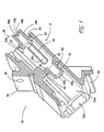
- Figure 1 is a perspective view of a fiber optic adapter in accordance with aspects of the present invention;
- Figure 2 is another perspective view of the fiber optic adapter of Figure 1;
- Figure 3 is a diagrammatic side view of the fiber optic adapter of Figure 1 illustrating fiber optic connectors being inserted into the adapter;
- Figure 4 is a sectional, exploded, perspective view of the fiber optic adapter of Figure 1;
- Figure 5 is another sectional, perspective view of a portion of the adapter shown in Figure 4;
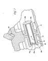
- Figure 6 is an enlarged, sectional, perspective view of a portion of the adapter shown in Figure 4 in an assembled state;
- Figure 7 is another enlarged sectional, perspective view of a portion of the adapter shown in Figure 4 in an assembled state;
- Figure 8 is an enlarged perspective view of a portion of adapter shown in Figure 1 including a fiber optic connector inserted into one of the cavities; and
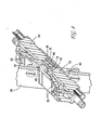
- Figure 9 is a sectional, perspective view of the adapter of Figure 1 showing fiber optic connectors inserted into the adapter.
-
- According to an aspect of the present invention, a fiber optic adapter is mountable through a panel opening on a panel. A fiber optic adapter in accordance with an aspect of the present invention provides a shielded connection between at least two fiber optic connectors each having an associated fiber optic line. For example, a shielded fiber optic adapter in accordance with the present invention may be mounted in an electrical equipment panel opening for connecting together a fiber optic connector on the outside of the panel to a fiber optic connector on the inside of the panel.
- Figure 1 illustrates a duplex fiber
optic adapter 10 having ahousing 15. Thehousing 15, in accordance with an aspect of the present invention, is formed from a conductive material. The conductive material inhibits EMI from leaking through the panel opening (shown in Figure 9) when theadapter 10 is mounted into such a panel opening. In one embodiment of the present invention, the conductive material comprises zinc, preferably formed by die casting. Preferably, the material in such an embodiment is a conventional ZAMAK 3 ™ or ZAMAK 7 ™, as will be understood by persons familiar with die casting materials. Other conductive materials such as copper or the like may be used without departing from the scope of the present invention. - As shown in Figures 1 and 2,
housing 15 defines at least afirst cavity 22a and asecond connector cavity 22b.First connector cavity 22a andsecond connector cavity 22b are disposed on opposite ends of the housing and are each formed to accept a conventional fiberoptic connector 28 such that when each cavity accepts a fiber connector, the connectors are in communication. Theadapter 10 preferably includes four connector cavities. Twoconnector cavities - Each fiber
optic connector 28 may communicate with the other fiber optic connector in the opposing paired connector cavity. Fiberoptic connector 28 preferably is conventional, as will be understood by persons familiar with fiber optic connector technology. In this regard, as best shown in Figures 3, 8, and 9, each fiberoptic connector 28 includes abody 29, aferrule 31 that protrudes outwardly frombody 28, and a mating mechanism orlatch 32. Ferrule 31 may be spring loaded as in conventional LC connectors, or may be non-spring loaded. The outer diameter offerrule 31 preferably has a tight tolerance to facilitate proper alignment thereof, as explained more fully below. - Fiber
optic adapter 10 also includeslatching recesses 30 on thehousing 15 of theadapter 10. Thelatching recesses 30 are formed to engage the fiber optic connector by acceptingmating latch 32. As such, the latching recesses 30 aid the connector cavities in holding or engaging thefiber optic connector 28. As shown in Figurel, the latching recesses 30 are apertures that extend through the wall of the housing. In particular, the latchingapertures 30 in Figure 1 and Figure 2 are formed on each of the first connector cavity andsecond connector cavity -
Fiber optic adapter 10 also includes aflange 20 that includes a mountingsurface 20a, which enables theadapter 10 to be coupled to anelectrical panel 60, as generally shown in Figures 3 and 9. The adapter is preferably oriented such that thecavities - As shown in Figure 1, mounting
flange 20 includes twofastening apertures 26 that are adapted to receive a fastening means or fasteners in order to couple the adapter and the panel together. The fasteners also provide the force to compress a gasket, as described more fully below. Such fastening means may include screws, rivets, pins or the like without departing from the present invention. - Figure 2 is a perspective view of the fiber optic adapter in accordance with an aspect of the present invention. Figure 2 shows
connector cavity connector cavities fiber optic adapter 10, as well as apanel 60 andadapter 10 mounted thereto.Panel 60 may be a panel of a piece of equipment or any other panel without departing from the scope of the present invention. Figure 3 shows theadapter 10 at a 45 degree angle in relation to the plane of thepanel 60 and the mountingsurface 20. - According to another aspect of the present invention, a
gasket 62 formed of a conductive material is disposed between a recessedsurface 61 of theflange 20 andpanel 60. Preferably, the recess 61 (as best shown in Figure 1) is formed inflange 20 for receivinggasket 62. Disposinggasket 62 inrecess 61, compared with inserting a sheet of gasket material between mountingsurfaces 20a offlange 20 andpanel 60, enables control of the amount of compression ofgasket 62, relieves uneven stress on theflange 20 and/orpanel 60, and diminishes the likelihood of over-torque of threaded fasteners. -
Gasket 62 serves to inhibits electromagnetic interference from leaking between the mounting surface and the panel. Under ordinary conditions (that is, for surfaces offlange 20 andpanel 60 manufactured according to conventional processes),gasket 62 may produce beneficial shielding or inhibition of leakage betweensurfaces panel 60 and/or mountingflange 20 are deformed, warped, have burrs, or are otherwise not effectively flat and smooth, in which electrical systems or circuits are especially sensitive, or in which EMI is high. -
Gasket 62 preferably is of the type that is compressible such that its shielding properties are enhanced upon compression. For example, the gasket may be formed of a compressible elastomeric material including conductive (or otherwise shielding) particles that may provide a barrier to EMI leakage upon compression of the compressible material. An example of such a material includes a silicone elastomer filled with nickel coated graphite carbon particles. Such gasket material may be as supplied by under the tradename NC-CONSIL™, by TECHNIT™ Company, was will be understood by persons familiar with such EMI shielding materials. Persons familiar with such shielding gaskets in light of the present disclosure will understand that the present invention encompasses any gasket that inhibits EMI leakage betweenflange 20 andpanel 60. - According to another aspect of the present invention,
adapter 10 includes amulti-part fitting 33 for receiving a pair of opposing fiber optic lines that are associated with thefiber optic connectors 28, as best shown in Figures 6, 7, and 9. Fitting 33 includes aframe post 35, aninsert post 36, and analignment sleeve 40. In this regard,housing 15 includes aninternal flange 42 that protrudes from a sidewall ofhousing 15 into and betweencavities reference numeral 42 for clarity and simplicity -- into and betweencavities Frame post 35, which is coupled to and supported byinternal flange 42, includes acylindrical sidewall 44a, aretainer 48a, and a landing orseat 45. -
Cylindrical sidewall 44a, which protrudes outwardly frominternal flange 42, forms abore 46a therethrough enabling communication betweencavities cavities Retainer 48a protrudes radially inwardly fromsidewall 44a at a distal end thereof (that is, opposite flange 42). An outer (that is, opposite internal flange 42) surface ofretainer 48a includes anannular bevel 49a.Seat 45 is a recessed portion offlange 42, andapertures 50 are formed throughinternal flange 42 inseat 45 about the circumference ofbore 46a, as best shown in Figures 4 and 5. - Insert post 36 includes a
cylindrical sidewall 44b, aflange 43, aretainer 48b, and plural tabs orfingers 52.Sidewall 44b forms alongitudinal bore 46b therethrough.Flange 43 extends outwardly from an end ofsidewall 44b.Fingers 52 preferably extend longitudinally outwardly fromflange 43. Preferably, three or four fingers are employed.Retainer 48b extends radially inwardly fromsidewall 44b at or near an end thereof that isopposite flange 43. An outer (that is, opposite internal flange 43) surface ofretainer 48b includes anannular bevel 49b. -
Alignment sleeve 40 is cylindrical so as to form abore 46c therethrough, and is configured to be insertable intobores retainers sleeve 40 is a conventional sleeve, such as for example formed of phosphor bronze (preferably for multi-mode operations) or a zirconia ceramic (preferably for single-mode operations), having a tight tolerance for aligning opposing ferrules of the fiber optic connectors. In this regard, because of alignment considerations relative to the small diameters of the operative fiber optic components, such as for example an 8 micron fiber optic core diameter for single mode fibers and a 62.5 micron core diameter of multiple mode fibers, the tolerance of the diameter ofbore 46c ofalignment sleeve 40 is often approximately one micron or less. - Referring to Figures 4 through 9 to describe the assembly of fitting 33, as well as the corresponding method according to another aspect of the present invention,
flange 42 andframe post 35, includingcylindrical sidewall 44a andretainer 48a, are preferably integrally formed withhousing 15 as part of a single casting, such as, for example, die casting of conventional materials as described above.Bore 46a ofpost 35 receivesalignment sleeve 40 therein such that a first end ofsleeve 40 contacts an inner portion ofretainer 48a. - Insert post 36 is disposed over an opposing second end of
sleeve 40 such thatframe seat 45 receivesinsert post flange 43 therein and insertpost retainer 48b may lightly contact the end ofsleeve 40 or may be disposed proximate the end ofsleeve 40 with a clearance therebetween so as to form either a fixed or a floating configuration.Fingers 52 are, thus, inserted and disposed inapertures 50. According to another aspect of the present invention,fingers 52 are deformed or coined so as to coupleposts internal flange 42proximate apertures 50 oppositeseat 45 have a chamfer to receive the deformed or coined portion offingers 52 such that, after deformation, the ends offingers 52 form rivets. -
Adapter 10, when formed of a conductive material as described above, provides EMI shielding. Such shielding is enhanced by minimizing the openings inadapter 10. In this regard, the maximum opening of conductive material through adapter 10 (that is, the internal diameter ofretainers - Coining tools configured to cooperate with the components described herein may be employed. For example, an anvil (not shown) having a circular opening may be disposed over
insert post 36 such that an anvil surface may urge against an outer portion of insert post flange 43 (that is, opposite fingers 52). A coining die (not shown) may be disposed overframe post 35 such that wedges or like deformation elements may urge against the distal tips offingers 52 so as to deform or coin the fingers. Thus, each of the anvil and the die may have a cut out to receiveposts - Coupling together posts 35 and 36 at ends thereof
opposite retainers retainers sleeve 40 without coining or modification of the distal ends ofposts - During insertion of a
connector 28 into a cavity (for example, 24b),ferrule 31 may contact a bevel (for example, 49b) to facilitate rough alignment and insertion offerrule 31 intosleeve bore 46c. Becauseinsert sleeve 40 is manufactured to the dimensional accuracy and precision to alignconnector ferrules 31,frame post 35 and insertpost 36 may be formed of a die cast material having tolerances achievable with conventional die casting techniques. Thus, even ifsleeve 40 is somewhat misaligned relative to bores 46a and 46b ofposts sleeve 40 is not co-linear or parallel to a longitudinal centerline of the cavity (for example, 24a and 24b), the opposingconnectors 28 may still be properly connected throughsleeve 40. At a predetermined point in the insertion process, latch 32 moves outwardly to clip intorecess 30 to removably affixconnector 28 toadapter 10. - The drawings illustrate aspects of the present invention with reference to a particular embodiment. The present invention, in not limited to the particular embodiment disclosed herein, but rather encompasses any configuration in accordance with the principles of the aspects of the invention disclosed herein. For example, the illustrated adapter is configured such that the longitudinal centerline of fiber optic connectors forms a 45 degree angle with the mating surface between the a panel and the adapter flange. The present invention, however, encompasses any configuration, including for example any orientation of the longitudinal centerline of fiber optic connectors relative to such mating surface. Further, the figures illustrate the coupling of
frame post 35 and insertpost 36 by riveted or coined fingers. The present invention encompassesfingers 52 being disposed inframe post 35 and theapertures 50 being formed ininsert post 36, rather than as shown in the figures. Further, the present invention encompasses any shape ofposts retainer alignment sleeve 40, as well as any means offastening posts
Claims (17)
- A fiber optic adapter (10) mountable through a panel opening on a panel (60) for providing a connection between at least two fiber optic connectors (28), the adapter comprising a housing (15) and an insert sleeve (40) at least first and second connector cavities (22a, 22b, 24a, 24b) disposed on opposite ends of the housing for receiving fiber optic connectors therein, the sleeve supported within the housing for receiving ferrules (31) of the fiber optic connectors therein,
characterized in that the housing (15) comprises a frame post (35) for supporting the sleeve being integrally formed with the housing, the housing and the frame post being formed from a conductive material. - A fiber optic adapter according to claim 1 characterized in that the housing and the frame post are integrally die cast.
- A fiber optic adapter according to claim 1 characterized in that a shielding gasket (62) is disposed between the adapter housing (15) and the panel (60).
- A fiber optic adapter according to claim 1 and 3 characterized in that the housing inhibits electromagnetic interference leakage through the panel opening and the shielding gasket inhibits electromagnetic interference from leaking between the housing and the panel.
- A fiber optic adapter according to claims 1 and 3 characterized in that the adapter comprises a flange (20) extending from the housing for coupling with the panel, the shielding gasket being disposed between the flange and the panel.
- A fiber optic adapter according to claim 3 characterized in that the gasket is compressible and includes conductive particles disposed in a compressible matrix.
- A fiber optic adapter according to claim 3 characterized in that the gasket is compressible and is a silicone elastomer filled with nickel coated graphite carbon particles.
- A fiber optic adapter according to claim 1 characterized in that the conductive material comprises zinc.
- A fiber optic adapter according to claim 1 characterized in that an insert post (36) is coupled to the frame post (35) , the alignment sleeve (40) being disposed in bores (46a, 46b) formed in the frame post and the insert post.
- A fiber optic adapter according to claim 9 characterized in that the frame post includes a retainer (48a) extending inwardly toward the frame post bore to secure an end of the alignment sleeve (40), the insert post including a retainer (48b) extending inwardly toward the insert post bore to secure another end of the alignment sleeve.
- The fiber optic adapter according to claim 9 characterized in that the frame post and the insert post are coupled together with fasteners.
- The fiber optic adapter according to claim 11 characterized in that the frame post includes an outer flange (42) and the insert post includes an outer flange (43), the insert post outer flange including fingers (52) extending therefrom extending into apertures (50) formed in the frame post outer flange, the fingers being deformed at distal ends thereof so as to couple the frame post outer flange and the insert post outer flange together.
- The fiber optic adapter according to claim 9 characterized in that each one of the frame post and the insert post are generally tubular.
- A fiber optic adapter according to claim 1 characterized in thata housing (15) formed of a conductive material and defining at least first and second connector cavities (22a, 22b, 24a, 24b) being disposed on opposite ends of the housing, the housing including a flange (20) for securing the adapter to the panel (60);a multi-part fitting (33) assembly disposed within the housing between the first and second connector cavities, the fitting assembly including a pair of members (35,36) mechanically coupled together and retaining an alignment sleeve (40) therebetween;a compressible gasket (62) formed of a conductive material disposed on the flange of the housing;such that the housing and the flange inhibit electromagnetic interference leakage through the panel.
- The fiber optic adapter according to claim 1 characterized in that each of end of the fitting assembly (33) includes a bevel (49b) for facilitating insertion of a portion of the fiber optic connector into the fitting assembly.
- A method of forming a fiber optic adapter (10) comprising the steps of:(a) providing a conductive housing (15) including first and second cavities formed therein, and a frame post (35) formed between the first and second cavities;(b) inserting an alignment sleeve (40) into a bore of the frame post;(c) inserting an insert post (36) over the alignment sleeve; and(d) mechanically coupling the frame post and the insert post together to secure the alignment sleeve therebetween such that a first fiber optic connector ferrule (31) is insertabble into a first end of the alignment sleeve and a second fiber optic connector ferrule (31) is insertable into an opposing second end of the alignment sleeve so as to operatively connect the first and second fiber optic connector ferrules.
- The method according to claim 16 characterized in that the providing step includes providing a die cast conductive housing.
Applications Claiming Priority (2)
| Application Number | Priority Date | Filing Date | Title |
|---|---|---|---|
| US858386 | 2001-05-16 | ||
| US09/858,386 US6568861B2 (en) | 2001-05-16 | 2001-05-16 | Fiber optic adapter |
Publications (2)
| Publication Number | Publication Date |
|---|---|
| EP1258759A2 true EP1258759A2 (en) | 2002-11-20 |
| EP1258759A3 EP1258759A3 (en) | 2004-03-17 |
Family
ID=25328183
Family Applications (1)
| Application Number | Title | Priority Date | Filing Date |
|---|---|---|---|
| EP02010241A Ceased EP1258759A3 (en) | 2001-05-16 | 2002-05-16 | Fiber optic adapter |
Country Status (5)
| Country | Link |
|---|---|
| US (1) | US6568861B2 (en) |
| EP (1) | EP1258759A3 (en) |
| JP (1) | JP2003014981A (en) |
| CN (1) | CN1203341C (en) |
| CA (1) | CA2386313A1 (en) |
Cited By (5)
| Publication number | Priority date | Publication date | Assignee | Title |
|---|---|---|---|---|
| WO2005054920A1 (en) * | 2003-11-26 | 2005-06-16 | Molex Incorporated | Adaptor for reducing emi |
| WO2006028814A1 (en) * | 2004-09-08 | 2006-03-16 | Molex Incorporated | Connector panel mount system |
| EP1674907A3 (en) * | 2004-12-22 | 2006-08-16 | CCS Technology, Inc. | Fibre optic cable connection device, plug and plug connector for optical fibre |
| EP1783521A1 (en) * | 2005-11-02 | 2007-05-09 | TKM Telekommunikation und Elektronik GmbH | Connector and RJ-45 connexion system. |
| EP2741114A1 (en) * | 2012-12-04 | 2014-06-11 | Sercomm Corporation | Mounting assembly for optical fiber flange |
Families Citing this family (61)
| Publication number | Priority date | Publication date | Assignee | Title |
|---|---|---|---|---|
| US6572272B2 (en) * | 2000-11-29 | 2003-06-03 | Berg Technology, Inc. | Angled optical connector mounting assembly |
| JP3954832B2 (en) * | 2001-10-17 | 2007-08-08 | ヒロセ電機株式会社 | Optical connector shield structure |
| US20030123811A1 (en) * | 2002-01-02 | 2003-07-03 | Lyon Gregory A. | Connector receptacle |
| US7029182B2 (en) * | 2002-03-01 | 2006-04-18 | Fci Americas Technology, Inc. | Angled optical connector adapter mounting assembly |
| US6863446B2 (en) * | 2002-03-05 | 2005-03-08 | Fci Americas Technology, Inc. | Optical connector adapter with latch inserts |
| AUPS120702A0 (en) | 2002-03-18 | 2002-04-18 | Kingfisher International Pty. Ltd. | An optical fibre connector system |
| US20040100784A1 (en) * | 2002-11-27 | 2004-05-27 | Willers Arthur G. | Apparatus and method for grounding EMI/RFI from data/signal cable |
| US6768860B2 (en) * | 2002-12-05 | 2004-07-27 | Jds Uniphase Inc. | High density fiber optic module |
| US6715928B1 (en) * | 2003-02-27 | 2004-04-06 | Molex Incorporated | Connector panel mount system |
| US6962445B2 (en) * | 2003-09-08 | 2005-11-08 | Adc Telecommunications, Inc. | Ruggedized fiber optic connection |
| US7223027B2 (en) * | 2003-12-30 | 2007-05-29 | Intel Corporation | Optical communications adapter module configured for use inside a XENPAK-sized module |
| US7008122B2 (en) * | 2003-12-30 | 2006-03-07 | Intel Corporation | Communications adapter module |
| US7172346B2 (en) * | 2003-12-30 | 2007-02-06 | Intel Corporation | Optical communications adapter, system and method |
| US20060073023A1 (en) * | 2004-09-17 | 2006-04-06 | Nanocoolers, Inc. | Integrated electromagnetic pump and power supply module |
| US7167628B2 (en) * | 2004-12-13 | 2007-01-23 | Adc Telecommunications, Inc. | Service blocker device and method |
| US7376323B2 (en) * | 2005-05-25 | 2008-05-20 | Adc Telecommunications, Inc. | Fiber optic adapter module |
| US20070120180A1 (en) * | 2005-11-25 | 2007-05-31 | Boaz Eitan | Transition areas for dense memory arrays |
| US7484896B2 (en) * | 2005-12-21 | 2009-02-03 | International Business Machines Corporation | Connector assembly with integrated electromagnetic shield |
| US7591595B2 (en) | 2007-01-24 | 2009-09-22 | Adc Telelcommunications, Inc. | Hardened fiber optic adapter |
| US7614797B2 (en) * | 2007-01-24 | 2009-11-10 | Adc Telecommunications, Inc. | Fiber optic connector mechanical interface converter |
| US7572065B2 (en) | 2007-01-24 | 2009-08-11 | Adc Telecommunications, Inc. | Hardened fiber optic connector |
| WO2008137897A1 (en) * | 2007-05-06 | 2008-11-13 | Adc Telecommunications, Inc. | Mechanical interface converter for making non-ruggedized fiber optic connectors compatible with a ruggedized fiber optic adapter |
| US7722258B2 (en) * | 2007-05-06 | 2010-05-25 | Adc Telecommunications, Inc. | Interface converter for SC fiber optic connectors |
| US7686519B2 (en) * | 2007-06-18 | 2010-03-30 | Adc Telecommunications, Inc. | Hardened fiber optic housing and cable assembly |
| US7744286B2 (en) | 2007-12-11 | 2010-06-29 | Adc Telecommunications, Inc. | Hardened fiber optic connection system with multiple configurations |
| US7867022B2 (en) * | 2009-04-08 | 2011-01-11 | Tyco Electronics Corporation | Brackets and receptacle assemblies with angled ports |
| WO2011140438A2 (en) | 2010-05-07 | 2011-11-10 | Amphenol Corporation | High performance cable connector |
| US8517613B2 (en) * | 2010-08-13 | 2013-08-27 | Tyco Electronics Corporation | Modular optical connector apparatus and method |
| US8382385B2 (en) * | 2011-01-14 | 2013-02-26 | Avago Technologies Fiber Ip (Singapore) Pte. Ltd | Optical transceiver module having an electromagnetic interference (EMI) cancellation device disposed therein, and an EMI cancelation method for use in an optical transceiver module |
| CN104704682B (en) | 2012-08-22 | 2017-03-22 | 安费诺有限公司 | High-frequency electrical connector |
| US9158074B2 (en) * | 2012-08-31 | 2015-10-13 | Adc Telecommunications, Inc. | Pivoting fiber optic cable connection device |
| US8827568B1 (en) * | 2013-02-28 | 2014-09-09 | Corning Cable Systems Llc | Fiber optic connector adapter module assemblies and methods |
| US9857538B2 (en) | 2013-03-15 | 2018-01-02 | Us Conec, Ltd. | Alignment adapter and alignment design for a connector therefor |
| ES2700963T3 (en) | 2013-06-27 | 2019-02-20 | CommScope Connectivity Belgium BVBA | Anchoring device for fiber optic cable for use with fiber optic connectors and methods of using it |
| WO2015112717A1 (en) | 2014-01-22 | 2015-07-30 | Amphenol Corporation | High speed, high density electrical connector with shielded signal paths |
| US9658409B2 (en) | 2015-03-03 | 2017-05-23 | Senko Advanced Components, Inc. | Optical fiber connector with changeable polarity |
| US10541482B2 (en) | 2015-07-07 | 2020-01-21 | Amphenol Fci Asia Pte. Ltd. | Electrical connector with cavity between terminals |
| EP3265857B1 (en) | 2015-11-24 | 2022-01-19 | Hewlett Packard Enterprise Development LP | Interfacing a ferrule with a socket |
| US10158194B2 (en) | 2016-01-15 | 2018-12-18 | Senko Advanced Components, Inc. | Narrow width adapters and connectors with spring loaded remote release |
| WO2017146722A1 (en) | 2016-02-26 | 2017-08-31 | Hewlett Packard Enterprise Development Lp | Optical connector assembly |
| US11420293B2 (en) | 2016-05-26 | 2022-08-23 | Corning Optical Communications LLC | Methods of ferrule reshaping for correcting core-to-ferrule concentricity errors, and optical fiber cable assemblies related to such methods |
| US10336644B2 (en) * | 2016-05-26 | 2019-07-02 | Corning Optical Communication Llc | Methods of ferrule reshaping for correcting core-to-ferrule concentricity errors, and optical fiber cable assemblies related to such methods |
| US9726830B1 (en) | 2016-06-28 | 2017-08-08 | Senko Advanced Components, Inc. | Connector and adapter system for two-fiber mechanical transfer type ferrule |
| TWI790798B (en) | 2016-08-23 | 2023-01-21 | 美商安芬諾股份有限公司 | Connector configurable for high performance |
| US10678006B2 (en) | 2016-09-30 | 2020-06-09 | Hewlett Packard Enterprise Development Lp | Optical interfaces with solder that passively aligns optical socket |
| US10228521B2 (en) | 2016-12-05 | 2019-03-12 | Senko Advanced Components, Inc. | Narrow width adapters and connectors with modular latching arm |
| US11822133B2 (en) | 2017-07-14 | 2023-11-21 | Senko Advanced Components, Inc. | Ultra-small form factor optical connector and adapter |
| US12001064B2 (en) | 2017-07-14 | 2024-06-04 | Senko Advanced Components, Inc. | Small form factor fiber optic connector with multi-purpose boot |
| US10281669B2 (en) | 2017-07-14 | 2019-05-07 | Senko Advance Components, Inc. | Ultra-small form factor optical connectors |
| US10795091B2 (en) | 2017-07-14 | 2020-10-06 | Hewlett Packard Enterprise Development Lp | Adaptor for optical component of optical connector |
| US10578811B2 (en) | 2017-11-29 | 2020-03-03 | Corning Optical Communications LLC | Methods of forming ferrules for optical fiber connectors, and optical fiber cable assemblies related to such methods |
| CN208862209U (en) | 2018-09-26 | 2019-05-14 | 安费诺东亚电子科技(深圳)有限公司 | A kind of connector and its pcb board of application |
| TW202439723A (en) | 2019-02-19 | 2024-10-01 | 美商安芬諾股份有限公司 | Electrical connector and method for manufacturing electrical connector |
| CN113631976B (en) | 2019-03-28 | 2023-06-09 | 扇港元器件有限公司 | Fiber optic adapter assembly |
| TW202534957A (en) | 2020-01-27 | 2025-09-01 | 美商Fci美國有限責任公司 | High speed, high density direct mate orthogonal connector |
| TW202607982A (en) | 2020-01-27 | 2026-02-16 | 美商Fci美國有限責任公司 | Electrical connector |
| CN215816516U (en) | 2020-09-22 | 2022-02-11 | 安费诺商用电子产品(成都)有限公司 | Electrical connector |
| CN213636403U (en) | 2020-09-25 | 2021-07-06 | 安费诺商用电子产品(成都)有限公司 | Electrical connector |
| CN115524799B (en) | 2021-06-25 | 2026-01-02 | 华为技术有限公司 | Adapter components and optical communication equipment |
| CN215266741U (en) | 2021-08-13 | 2021-12-21 | 安费诺商用电子产品(成都)有限公司 | High-performance card connector meeting high-bandwidth transmission |
| CN114114566B (en) * | 2021-10-09 | 2023-01-06 | 华为技术有限公司 | connection box |
Citations (1)
| Publication number | Priority date | Publication date | Assignee | Title |
|---|---|---|---|---|
| US6193420B1 (en) * | 1999-08-13 | 2001-02-27 | Lucent Technologies Inc. | Shielded optical fiber adaptor |
Family Cites Families (15)
| Publication number | Priority date | Publication date | Assignee | Title |
|---|---|---|---|---|
| JPS5630111A (en) * | 1979-08-21 | 1981-03-26 | Nec Corp | Receptacle for optical communication |
| US4334730A (en) * | 1979-11-26 | 1982-06-15 | Bunker Ramo Corporation | Insulated from ground bulkhead adapter |
| JPS62121406A (en) * | 1985-11-22 | 1987-06-02 | Nec Corp | Connection adapter for optical connector |
| US5315684A (en) * | 1991-06-12 | 1994-05-24 | John Mezzalingua Assoc. Inc. | Fiber optic cable end connector |
| US5506922A (en) * | 1994-08-01 | 1996-04-09 | Molex Incorporated | Fiber optic component assembly with a movable protective shield |
| TW358552U (en) * | 1995-08-02 | 1999-05-11 | Molex Inc | Adapter for interconnecting optical fiber connectors |
| US5825955A (en) * | 1997-02-05 | 1998-10-20 | Molex Incorporated | Fiber optic diversion connector |
| US5818992A (en) * | 1997-03-03 | 1998-10-06 | Lucent Technologies Inc. | Thermo-plastic optical terminator having a glass-transition temperature greater than 80° C. |
| US6349164B1 (en) * | 1997-05-15 | 2002-02-19 | Siemens Aktiengesellschaft | Shielding apparatus for a light waveguide plug arrangement |
| US6027252A (en) * | 1997-12-19 | 2000-02-22 | The Whitaker Corporation | Simplified fiber optic receptacle |
| US5923805A (en) * | 1997-12-22 | 1999-07-13 | Lucent Technologies Inc. | Connector for plastic optical fiber |
| US6220763B1 (en) * | 1998-09-04 | 2001-04-24 | Lucent Technologies Inc. | Optical fiber buildout system |
| US6254278B1 (en) * | 1999-10-06 | 2001-07-03 | Lucent Technologies Inc. | Optical fiber tunable connector adapter |
| US6364537B1 (en) * | 2000-02-08 | 2002-04-02 | The Siemon Company | Dual polarity fiber optic adapter |
| US6402393B1 (en) * | 2000-02-29 | 2002-06-11 | Lucent Technologies Inc. | Interconnection system for optical circuit boards |
-
2001
- 2001-05-16 US US09/858,386 patent/US6568861B2/en not_active Expired - Fee Related
-
2002
- 2002-05-14 CA CA002386313A patent/CA2386313A1/en not_active Abandoned
- 2002-05-16 JP JP2002141345A patent/JP2003014981A/en not_active Withdrawn
- 2002-05-16 CN CNB021197709A patent/CN1203341C/en not_active Expired - Fee Related
- 2002-05-16 EP EP02010241A patent/EP1258759A3/en not_active Ceased
Patent Citations (1)
| Publication number | Priority date | Publication date | Assignee | Title |
|---|---|---|---|---|
| US6193420B1 (en) * | 1999-08-13 | 2001-02-27 | Lucent Technologies Inc. | Shielded optical fiber adaptor |
Non-Patent Citations (2)
| Title |
|---|
| LECKLIDER T.: "Speed, and Packaging Drive Shielding/Suppression Market", EE EVALUATION ENGINEERING, January 1999 (1999-01-01), pages 69 - 78 * |
| Retrieved from the Internet <URL:http://web.archive.org/web/20000829100602/tecknit.com/REFA_I/d_ce99.pdf> [retrieved on 20001203] * |
Cited By (6)
| Publication number | Priority date | Publication date | Assignee | Title |
|---|---|---|---|---|
| WO2005054920A1 (en) * | 2003-11-26 | 2005-06-16 | Molex Incorporated | Adaptor for reducing emi |
| WO2006028814A1 (en) * | 2004-09-08 | 2006-03-16 | Molex Incorporated | Connector panel mount system |
| EP1674907A3 (en) * | 2004-12-22 | 2006-08-16 | CCS Technology, Inc. | Fibre optic cable connection device, plug and plug connector for optical fibre |
| EP1783521A1 (en) * | 2005-11-02 | 2007-05-09 | TKM Telekommunikation und Elektronik GmbH | Connector and RJ-45 connexion system. |
| US7326087B2 (en) | 2005-11-02 | 2008-02-05 | Tkm Telekommunikation Und Elektronik Gmbh | Plug-in connector and coupling in the form of an RJ45 connector jack |
| EP2741114A1 (en) * | 2012-12-04 | 2014-06-11 | Sercomm Corporation | Mounting assembly for optical fiber flange |
Also Published As
| Publication number | Publication date |
|---|---|
| CN1203341C (en) | 2005-05-25 |
| CN1385721A (en) | 2002-12-18 |
| CA2386313A1 (en) | 2002-11-16 |
| US20020172469A1 (en) | 2002-11-21 |
| EP1258759A3 (en) | 2004-03-17 |
| US6568861B2 (en) | 2003-05-27 |
| JP2003014981A (en) | 2003-01-15 |
Similar Documents
| Publication | Publication Date | Title |
|---|---|---|
| US6568861B2 (en) | Fiber optic adapter | |
| US6422759B1 (en) | Fiber optic connector | |
| US6579013B2 (en) | Optical fiber coupler and an optical fiber coupler incorporated within a transceiver module | |
| US6464408B1 (en) | Fiber optic connectors | |
| EP1148366B1 (en) | Eccentricity adjustable optical fiber connector | |
| US4789351A (en) | Blind mating connector with snap ring insertion | |
| CN100385279C (en) | Device for connecting optical cables | |
| US9261653B2 (en) | Fiber optic plug assembly and optical connector system | |
| EP1091227B1 (en) | An optical connector having a housing assembly that is comprised of polyphenylsulfone | |
| EP1174959B1 (en) | EMI gasket for connector assemblies | |
| EP2987013B1 (en) | Optical connector assembly | |
| EP3201668B1 (en) | Ferrule assembly for a fiber optic connector | |
| JP3465189B2 (en) | Optical fiber connector and assembly method thereof | |
| US6193420B1 (en) | Shielded optical fiber adaptor | |
| WO1995022775A1 (en) | One-piece sc fiber optic connector | |
| US6891735B2 (en) | EMI shielded adapter for fiber optic connector systems | |
| GB2297007A (en) | Optical transceiver module | |
| JP3120354U (en) | Die-cast adapter | |
| US20230142093A1 (en) | Fiber optic adapters for use with fiber optic connectors and methods for coupling fiber optic connectors | |
| CN216956452U (en) | EMI shield and optical fiber switching module with same | |
| US20020159712A1 (en) | EMI shield for fiber optic adapter | |
| US6840681B2 (en) | Tandem type optical connector | |
| US20230168438A1 (en) | Fiber optic adapter | |
| JP2003270489A (en) | Optical connector adapter and optical connector plug | |
| CN113740975A (en) | Ferrule holder assembly |
Legal Events
| Date | Code | Title | Description |
|---|---|---|---|
| PUAI | Public reference made under article 153(3) epc to a published international application that has entered the european phase |
Free format text: ORIGINAL CODE: 0009012 |
|
| AK | Designated contracting states |
Kind code of ref document: A2 Designated state(s): AT BE CH CY DE DK ES FI FR GB GR IE IT LI LU MC NL PT SE TR |
|
| AX | Request for extension of the european patent |
Free format text: AL;LT;LV;MK;RO;SI |
|
| PUAL | Search report despatched |
Free format text: ORIGINAL CODE: 0009013 |
|
| AK | Designated contracting states |
Kind code of ref document: A3 Designated state(s): AT BE CH CY DE DK ES FI FR GB GR IE IT LI LU MC NL PT SE TR |
|
| AX | Request for extension of the european patent |
Extension state: AL LT LV MK RO SI |
|
| 17P | Request for examination filed |
Effective date: 20040708 |
|
| AKX | Designation fees paid |
Designated state(s): AT BE CH CY DE DK ES FI FR GB GR IE IT LI LU MC NL PT SE TR |
|
| GRAP | Despatch of communication of intention to grant a patent |
Free format text: ORIGINAL CODE: EPIDOSNIGR1 |
|
| GRAS | Grant fee paid |
Free format text: ORIGINAL CODE: EPIDOSNIGR3 |
|
| STAA | Information on the status of an ep patent application or granted ep patent |
Free format text: STATUS: THE APPLICATION HAS BEEN REFUSED |
|
| 18R | Application refused |
Effective date: 20070716 |