US9857538B2 - Alignment adapter and alignment design for a connector therefor - Google Patents

Alignment adapter and alignment design for a connector therefor Download PDF

Info

Publication number
US9857538B2
US9857538B2 US14/214,931 US201414214931A US9857538B2 US 9857538 B2 US9857538 B2 US 9857538B2 US 201414214931 A US201414214931 A US 201414214931A US 9857538 B2 US9857538 B2 US 9857538B2
Authority
US
United States
Prior art keywords
adapter
plug
ferrule
opening
grooves
Prior art date
Legal status (The legal status is an assumption and is not a legal conclusion. Google has not performed a legal analysis and makes no representation as to the accuracy of the status listed.)
Active, expires
Application number
US14/214,931
Other versions
US20160161680A1 (en
Inventor
Hiep Nguyen
Darrell R. Childers
Michael E. Hughes
Jillcha Fekadu Wakjira
Joseph P. Howard
Current Assignee (The listed assignees may be inaccurate. Google has not performed a legal analysis and makes no representation or warranty as to the accuracy of the list.)
US Conec Ltd
Original Assignee
US Conec Ltd
Priority date (The priority date is an assumption and is not a legal conclusion. Google has not performed a legal analysis and makes no representation as to the accuracy of the date listed.)
Filing date
Publication date
Family has litigation
First worldwide family litigation filed litigation Critical https://patents.darts-ip.com/?family=56094163&utm_source=google_patent&utm_medium=platform_link&utm_campaign=public_patent_search&patent=US9857538(B2) "Global patent litigation dataset” by Darts-ip is licensed under a Creative Commons Attribution 4.0 International License.
Priority to US14/214,931 priority Critical patent/US9857538B2/en
Application filed by US Conec Ltd filed Critical US Conec Ltd
Assigned to US CONEC, LTD. reassignment US CONEC, LTD. ASSIGNMENT OF ASSIGNORS INTEREST (SEE DOCUMENT FOR DETAILS). Assignors: HUGHES, MICHAEL E., CHILDERS, DARRELL R., HOWARD, JOSEPH P., NGUYEN, HIEP, WAKJIRA, JILLCHA FEKADU
Publication of US20160161680A1 publication Critical patent/US20160161680A1/en
Priority to US15/855,750 priority patent/US10156684B2/en
Priority to US15/855,788 priority patent/US10712509B2/en
Publication of US9857538B2 publication Critical patent/US9857538B2/en
Application granted granted Critical
Priority to US16/214,317 priority patent/US10890723B2/en
Priority to US17/145,864 priority patent/US11385415B2/en
Priority to US17/857,300 priority patent/US20220357525A1/en
Priority to US18/483,949 priority patent/US11880075B1/en
Active legal-status Critical Current
Adjusted expiration legal-status Critical

Links

Images

Classifications

    • GPHYSICS
    • G02OPTICS
    • G02BOPTICAL ELEMENTS, SYSTEMS OR APPARATUS
    • G02B6/00Light guides; Structural details of arrangements comprising light guides and other optical elements, e.g. couplings
    • G02B6/24Coupling light guides
    • G02B6/36Mechanical coupling means
    • G02B6/38Mechanical coupling means having fibre to fibre mating means
    • G02B6/3807Dismountable connectors, i.e. comprising plugs
    • G02B6/3873Connectors using guide surfaces for aligning ferrule ends, e.g. tubes, sleeves, V-grooves, rods, pins, balls
    • G02B6/3874Connectors using guide surfaces for aligning ferrule ends, e.g. tubes, sleeves, V-grooves, rods, pins, balls using tubes, sleeves to align ferrules
    • G02B6/3878Connectors using guide surfaces for aligning ferrule ends, e.g. tubes, sleeves, V-grooves, rods, pins, balls using tubes, sleeves to align ferrules comprising a plurality of ferrules, branching and break-out means
    • G02B6/3879Linking of individual connector plugs to an overconnector, e.g. using clamps, clips, common housings comprising several individual connector plugs
    • GPHYSICS
    • G02OPTICS
    • G02BOPTICAL ELEMENTS, SYSTEMS OR APPARATUS
    • G02B6/00Light guides; Structural details of arrangements comprising light guides and other optical elements, e.g. couplings
    • G02B6/24Coupling light guides
    • G02B6/36Mechanical coupling means
    • G02B6/38Mechanical coupling means having fibre to fibre mating means
    • G02B6/3807Dismountable connectors, i.e. comprising plugs
    • G02B6/381Dismountable connectors, i.e. comprising plugs of the ferrule type, e.g. fibre ends embedded in ferrules, connecting a pair of fibres
    • G02B6/3817Dismountable connectors, i.e. comprising plugs of the ferrule type, e.g. fibre ends embedded in ferrules, connecting a pair of fibres containing optical and electrical conductors
    • GPHYSICS
    • G02OPTICS
    • G02BOPTICAL ELEMENTS, SYSTEMS OR APPARATUS
    • G02B6/00Light guides; Structural details of arrangements comprising light guides and other optical elements, e.g. couplings
    • G02B6/24Coupling light guides
    • G02B6/36Mechanical coupling means
    • G02B6/38Mechanical coupling means having fibre to fibre mating means
    • G02B6/3807Dismountable connectors, i.e. comprising plugs
    • G02B6/381Dismountable connectors, i.e. comprising plugs of the ferrule type, e.g. fibre ends embedded in ferrules, connecting a pair of fibres
    • G02B6/3825Dismountable connectors, i.e. comprising plugs of the ferrule type, e.g. fibre ends embedded in ferrules, connecting a pair of fibres with an intermediate part, e.g. adapter, receptacle, linking two plugs
    • GPHYSICS
    • G02OPTICS
    • G02BOPTICAL ELEMENTS, SYSTEMS OR APPARATUS
    • G02B6/00Light guides; Structural details of arrangements comprising light guides and other optical elements, e.g. couplings
    • G02B6/24Coupling light guides
    • G02B6/36Mechanical coupling means
    • G02B6/38Mechanical coupling means having fibre to fibre mating means
    • G02B6/3807Dismountable connectors, i.e. comprising plugs
    • G02B6/3873Connectors using guide surfaces for aligning ferrule ends, e.g. tubes, sleeves, V-grooves, rods, pins, balls
    • G02B6/3881Connectors using guide surfaces for aligning ferrule ends, e.g. tubes, sleeves, V-grooves, rods, pins, balls using grooves to align ferrule ends
    • GPHYSICS
    • G02OPTICS
    • G02BOPTICAL ELEMENTS, SYSTEMS OR APPARATUS
    • G02B6/00Light guides; Structural details of arrangements comprising light guides and other optical elements, e.g. couplings
    • G02B6/24Coupling light guides
    • G02B6/36Mechanical coupling means
    • G02B6/38Mechanical coupling means having fibre to fibre mating means
    • G02B6/3807Dismountable connectors, i.e. comprising plugs
    • G02B6/3873Connectors using guide surfaces for aligning ferrule ends, e.g. tubes, sleeves, V-grooves, rods, pins, balls
    • G02B6/3885Multicore or multichannel optical connectors, i.e. one single ferrule containing more than one fibre, e.g. ribbon type

Definitions

  • An alternative way to align the ferrules to each other is to align the ferrule holders to one another through features in the adapter. Rather than using the sides of the ferrule holder to align the ferrule holder to the adapter, top and bottom keys on the ferrule holder align the ferrule holder relative to the adapter in the x-direction. The orientation of the ferrule holder is controlled by the width difference between the top and the bottom key. The height of the ferrule holder aligns the ferrule holder in the y direction. A plug is used to assemble a plurality of the ferrule holders together.
  • the ferrule holders protrude through the plug so the ferrule holder features can be aligned in the adapter after the plug engages the adapter and aligns the ferrule holders with their own structures.
  • the alignment in the X and Y directions between the ferrule holder and the adapter are maintained within 100 microns, preferably within 50 microns.
  • the ferrule holders are relatively loosely held within the plug so as to not over constrain the ferrule holders in the adapter (greater than 100 microns).
  • the grooves within the adapter that aligns the ferrule holders is one continuous feature for both sides of the adapter and the mating ferrule holders. By making the groove one continuous feature for both sides, the alignment the mating ferrule holders is guaranteed.
  • the size of the groove is critical but the true position of the alignment feature relative to the adapter-to-plug alignment feature is not critical.
  • This alignment mechanism By using this alignment mechanism, large arrays of ferrule holders can be manufactured. Only the size of the alignment mechanism in the ferrule holder and the size of the alignment mechanism in the adapter must be maintained. The true position tolerances are significantly reduced.
  • an adapter and adapter assembly with novel alignment features is provided to engage with alignment features on a plug, which is turn assists in aligning the ferrule holders with alignment grooves in the adapter.
  • the present invention is directed to an adapter for aligning fiber optic ferrules inserted from opposing sides that includes a main body having an opening extending between a first side and a second side, the first side and the second side separated by a central portion, at least one groove in a top surface and a bottom surface of the first side and the second side, and a plurality of grooves disposed in a top surface and the bottom surface of the central portion, each of the plurality of grooves extending through the central portion from the first side to the second side.
  • a ferrule holder in yet another aspect, includes a main body having a central opening to resiliently retain a fiber optic ferrule therein, a central opening in the main body and extending from a first end to a second end to resiliently retain a fiber optic ferrule therein, the first end having an opening therein and in communication with the central opening, the second end opposite the first end and through which optical fibers extend, and a projection on opposite outside surfaces of the main body to engage a corresponding groove in an adapter.
  • the present invention is also directed to a fiber optic connector that includes a plurality of ferrule holders, each of the plurality of ferrule holders having a central opening extending from a first end to a second end to resiliently retain a fiber optic ferrule therein, the ferrule holder having an opening in first end in communication with the central opening, the second end opposite the first end and through which optical fibers extend, each of the plurality of ferrule holders having a projection on opposite outside surfaces to engage a corresponding groove in the adapter, and a plug having an outside surface and an inside surface, the inside surface defining an opening through the plug to hold a plurality of ferrule holders therein adjacent one another, the plug having grooves in the inside surface to engage the projections from the plurality of ferrule holders to align and orient the ferrule holders in the plug
  • FIG. 1 is a perspective view of one embodiment of an adapter assembly according to the present invention
  • FIG. 2 is an exploded view of the adapter assembly of FIG. 1 ;
  • FIG. 3 is a perspective view of a cut-away view of the adapter of FIG. 1 ;
  • FIG. 4 is a front elevational view of the adapter of FIG. 1 ;
  • FIG. 5A is a top perspective view of one embodiment of a ferrule holder and ferrule that can be used in the adapter assembly of FIG. 1 ;
  • FIG. 5B is a bottom perspective view of the ferrule holder and ferrule of FIG. 5 a;
  • FIG. 5C is a front view of the ferrule holder and ferrule of FIG. 5 a;
  • FIG. 6A is a top perspective view of a plug and ferrule holders according to the present invention.
  • FIG. 6B is a bottom perspective view of the plug and ferrule holders of FIG. 6A ;
  • FIG. 6C is a front elevational view of the plug and ferrule holders of FIG. 6A ;
  • FIG. 7A is a partial cross sectional view of a portion of a ferrule holder of FIG. 5 ;
  • FIG. 7B is a partial cross sectional view of a portion of the center portion of the adapter
  • FIG. 8 is a cross sectional view of the adapter assembly in the center of the adapter assembly.
  • FIG. 9 is a cross sectional view of the adapter assembly through a ferrule holder and ferrule.
  • the adapter assembly 10 includes an adapter 100 , a plug 200 and a ferrule holder 300 .
  • the adapter assembly 10 is used to align ferrules 12 to other ferrules in a tightly controlled manner and in a tighter space than has been possible before.
  • the ferrules 12 are typically multi-fiber ferrules, particularly MT type ferrules, but the present invention may include other types of ferrules.
  • the ferrules 12 are disposed within the ferrule holder 300 and have optical fibers 14 secured therein, which may be loose optical fibers, ribbonized optical fibers, or optical fibers in any other configuration.
  • the ferrules 12 are resiliently held in the ferrule holders 300 using a spring push 16 that engages a spring 18 .
  • the spring 18 then presses on a pin keeper 20 , as is known in the art, to bias the ferrules 12 forward in the ferrule holder 300 .
  • the ferrules 12 are held somewhat loosely within the ferrule holder 300 so that they can move relative to the ferrule holder 300 to align with other ferrules 12 that are inserted in the adapter 100 from the other side.
  • the ferrule holders 300 are inserted into the plug 200 and they are also loosely held in the plug 200 . That is, there is typically more than 100 microns of movement in the x and y directions (See FIG. 4 .) available to the ferrule holder 300 in the plug 200 , as explained in more detail below.
  • the ferrule holder 300 has a main body 302 with a central opening 304 that extends from a first end 306 to a second end 308 to house the fiber optic ferrules 12 .
  • the first end 306 has an opening 310 therein to allow access to the ferrule 12 .
  • the ferrule 12 may or may not exit the main body 302 . That is, the ferrule 12 may extend beyond the main body 302 as shown in the figures or it may be flush with the first end 306 .
  • second end 308 allows for the optical fibers 14 (shown in FIGS. 5A and 5B to have a boot and a covering) to exit the ferrule holder 300 .
  • the ferrule holder 300 has a top surface 312 and a bottom surface 314 , with a cantilevered latch 316 to engage the plug 200 .
  • the top surface 312 has a projection 320 and the bottom surface 314 has a projection 322 .
  • the projections 320 , 322 are preferably elongated and have a chamfered front end.
  • the projections 320 , 322 are used to engage grooves in the plug 200 and the adapter 100 to position the ferrule holders 300 with precision in the adapter 100 .
  • the projection 320 has a width that is different that the width of projection 322 so as to act as a key in inserting the ferrule holder 300 in the plug 200 .
  • projection 320 is wider than projection 322 , it could be opposite in that projection 320 is more narrow than projection 322 .
  • the projections 320 , 322 are preferably on the top and the bottom surfaces 312 , 314 of the ferrule holder 300 to allow, as illustrated below, more ferrule holders to be inserted into the adapter 100 and the plug 200 .
  • the projections 320 , 322 are used to position the ferrules 12 in the adapter in the x and y directions, eliminating the need for side walls to position the ferrule holders 300 and the ferrules 12 .
  • the plug 200 will now be described relative to FIGS. 6A-6C .
  • the plug 200 has an outside surface 202 and an inside surface 204 .
  • the inside surface 204 defines an opening 206 therethrough to allow the ferrule holders 300 to be inserted therein.
  • the inside surface 204 has a plurality of grooves 208 on a top side 210 and a corresponding plurality of grooves 212 on the bottom side 214 .
  • the grooves 208 and 212 are dimensioned to accept the projections 320 , 322 from the ferrule holders 300 .
  • the ferrule holders 300 are adjacent to one another, that is side-by-side without any material from the plug 200 therebetween. Applicant means that by using the term adjacent herein, there is no structure that comes between the neighboring ferrule holders 300 .
  • the outside surface 202 also has a projection 220 on the top of the plug 200 , seen in FIG. 6A , and also a projection 222 on the bottom of the plug 200 , seen in FIG. 6B .
  • projection 220 has a width that is different that the width of projection 222 so as to act as a key in inserting the plug 200 into the adapter 100 . While the projection 220 is narrower than projection 222 , it could be opposite in that projection 220 is wider than projection 222 .
  • the plug 200 also has two cantilevered latches 230 on the sides to engage corresponding structure on the adapter 100 . There are also latch receptacles 232 on the top side of the plug 200 to engage the latches 316 of the ferrule holders 300 .
  • the grooves 208 and 212 in plug 200 are dimensioned to accept the projections 320 , 322 from the ferrule holders 300 .
  • the adapter 100 has a main body 102 with an opening 104 extending between a first side 106 and a second side 108 .
  • the first side 106 and a second side 108 are separated by a central portion 110 .
  • the first side 106 has a top surface 112 and a bottom surface 114 .
  • the top surface 112 has a groove 116 and the bottom surface 114 has a groove 118 .
  • the grooves 116 , 118 correspond to the projections 220 , 222 from the plug 200 .
  • the location of the wider groove in the adapter 100 will correspond with the wider projection on the plug 200 .
  • the adapter has the center portion 110 .
  • Center portion 110 preferably has a wall 130 that extends across the opening 104 in the adapter 100 and divides the center portion 110 in half.
  • the center portion 110 also has a raised bottom portion 132 and a dropped top portion 134 that narrows the opening 104 in the center portion 110 .
  • the wall 130 preferably extends from the raised bottom portion 132 and a dropped top portion 134 or it may be excluded completely if there is no EMI concerns with the adapter 100 .
  • the wall 130 has a plurality of openings 136 that are sized to allow the ferrules 12 to pass therethrough to engage a corresponding ferrule 12 .
  • the openings 136 should be sized to allow the ferrule holders to also extend therethrough.
  • the adapter 100 may also have an elastomeric gasket 150 that encircles an external surface of the adapter 100 to provide EMI shielding.
  • the raised bottom portion 132 and a dropped top portion 134 also have a plurality of grooves 140 , 142 , respectively, that extend completely across the central portion 110 .
  • the grooves 140 , 142 are like those in the plug 200 , in that they are to engage the projections 320 , 322 from the ferrule holders 300 .
  • the grooves 140 , 142 preferably extend completely across the center portion 110 as they are formed with the same insert in the mold. Therefore, the grooves 140 , 142 are sure to align the ferrule holders 300 on each side of the adapter 100 as they are inserted into the adapter 100 .
  • the projections 220 , 222 from the plug 200 engage the grooves 116 , 118 on the top surface 112 and the bottom surface 114 to roughly align the ferrule holders 300 with the center portion 110 and the plurality of grooves 140 in particular.
  • the projections 320 , 322 from the ferrule holders 300 engage plurality of grooves 140 , 142 to align the ferrule holders 300 with the adapter and the openings 136 in the wall 130 .
  • the ferrules in the ferrule holders on the other side will be in alignment with the first side.
  • the position of the ferrule holders 300 on the first side 106 of the adapter relative to the ferrule holders 300 on the second side 108 is what allows the optical ferrules to be aligned with one another. There is no need, as discussed above, to worry about the stacking of tolerances as in the prior art.
  • the positioning of the projections 320 , 322 on the ferrule holders 300 relative to the plurality of grooves 140 , 142 is important. With reference to FIGS. 7A and 7B , the projections 320 , 322 are used to control the x and y locations of the ferrule holders 300 .
  • the surfaces 350 of the projections 320 , 322 ( FIG. 7A ) align with the surfaces 150 in the adapter ( FIG.
  • the surfaces 352 of the ferrule holder 300 align with the surfaces 352 of the raised bottom portion 132 and the dropped top portion 134 of the center portion 110 to control the y direction of the ferrule holder 300 relative to the adapter 100 .
  • the surfaces of the projections 320 , 322 could also align in the y direction, given that they are parallel to the surfaces 352 .
  • FIG. 8 A cross section of the adapter assembly 10 is illustrated in FIG. 8 through the center of the adapter assembly. This illustrates the projections 220 , 200 in the openings 116 , 118 of the adapter 100 .
  • FIG. 9 is a cross sectional view of the adapter assembly 10 through a ferrule holder and ferrule illustrating the engagement of the projections 320 , 322 in the openings 140 , 142 .

Abstract

An adapter with novel alignment features engages alignment features on a plug, providing general alignment of the ferrule holders and ferrules in the plug. After the plug engages the adapter, the ferrule holders engage a second set of alignment features in the adapter to provide fine alignment for the ferrules.

Description

REFERENCE TO RELATED CASE
This application claims priority under 35 U.S.C. §119 (e) to provisional application No. 61/789,499 filed on Mar. 15, 2013, the contents of which is hereby incorporated by reference in its entirety.
BACKGROUND OF THE INVENTION Field of the Invention
There is a need for fiber optic connectors with fiber optic ferrules that are ganged together with a tight pitch between those fiber optic ferrules. Such a design allows for many fiber optic ferrules to be connected simultaneously while occupying less space. In addition, it allows the fiber optic ferrules to be organized in a prearranged routing of the optical fibers so that the complexity of fiber optic connector routing is reduced for the user. Typically, these ganged fiber optic ferrules are mounted into a single housing and the housings are then mated to one another. The alignment between a pair of ferrules to be mated is complex and requires tight tolerances because there is a tolerance stack-up that includes the true position of the fiber optic ferrule relative to the housing. By requiring a tight tolerance of the housing relative to the fiber optic ferrule, the designs are expensive to design, maintain, and to scale to various fiber optic ferrule counts. It is also difficult to scale to very large arrays of fiber optic ferrules within one housing due to the true position tolerance required for every fiber optic ferrule to the housings and also the larger distances from the fiber optic ferrules to the housings.
An alternative way to align the ferrules to each other is to align the ferrule holders to one another through features in the adapter. Rather than using the sides of the ferrule holder to align the ferrule holder to the adapter, top and bottom keys on the ferrule holder align the ferrule holder relative to the adapter in the x-direction. The orientation of the ferrule holder is controlled by the width difference between the top and the bottom key. The height of the ferrule holder aligns the ferrule holder in the y direction. A plug is used to assemble a plurality of the ferrule holders together. The ferrule holders protrude through the plug so the ferrule holder features can be aligned in the adapter after the plug engages the adapter and aligns the ferrule holders with their own structures. The alignment in the X and Y directions between the ferrule holder and the adapter are maintained within 100 microns, preferably within 50 microns. The ferrule holders are relatively loosely held within the plug so as to not over constrain the ferrule holders in the adapter (greater than 100 microns). The grooves within the adapter that aligns the ferrule holders is one continuous feature for both sides of the adapter and the mating ferrule holders. By making the groove one continuous feature for both sides, the alignment the mating ferrule holders is guaranteed. The size of the groove is critical but the true position of the alignment feature relative to the adapter-to-plug alignment feature is not critical. By using this alignment mechanism, large arrays of ferrule holders can be manufactured. Only the size of the alignment mechanism in the ferrule holder and the size of the alignment mechanism in the adapter must be maintained. The true position tolerances are significantly reduced.
Thus, an adapter and adapter assembly with novel alignment features is provided to engage with alignment features on a plug, which is turn assists in aligning the ferrule holders with alignment grooves in the adapter.
SUMMARY OF THE INVENTION
The present invention is directed to an adapter for aligning fiber optic ferrules inserted from opposing sides that includes a main body having an opening extending between a first side and a second side, the first side and the second side separated by a central portion, at least one groove in a top surface and a bottom surface of the first side and the second side, and a plurality of grooves disposed in a top surface and the bottom surface of the central portion, each of the plurality of grooves extending through the central portion from the first side to the second side.
According to another aspect of the present invention, adapter assembly for aligning one plurality of optical ferrules to another plurality of optical ferrules includes an adapter having an opening extending between a first side and a second side, the adapter having a plurality of grooves in the opening and extending in a direction from the first side to the second side, a plurality of ferrule holders, each of the plurality of ferrule holders having a central opening extending from a first end to a second end to resiliently retain a fiber optic ferrule therein, each of the plurality of ferrule holders having an opening in first end and in communication with the central opening, the second end opposite the first end and through which optical fibers extend, each of the plurality of ferrule holders having a projection on opposite outside surfaces to engage a corresponding groove in the adapter, and a plug having an outside surface and an inside surface, the inside surface defining an opening through the plug to hold a plurality of ferrule holders therein adjacent one another, the plug having grooves in the inside surface to engage the projections from the plurality of ferrule holders to align and orient the ferrule holders in the plug.
In yet another aspect, a ferrule holder includes a main body having a central opening to resiliently retain a fiber optic ferrule therein, a central opening in the main body and extending from a first end to a second end to resiliently retain a fiber optic ferrule therein, the first end having an opening therein and in communication with the central opening, the second end opposite the first end and through which optical fibers extend, and a projection on opposite outside surfaces of the main body to engage a corresponding groove in an adapter.
The present invention is also directed to a fiber optic connector that includes a plurality of ferrule holders, each of the plurality of ferrule holders having a central opening extending from a first end to a second end to resiliently retain a fiber optic ferrule therein, the ferrule holder having an opening in first end in communication with the central opening, the second end opposite the first end and through which optical fibers extend, each of the plurality of ferrule holders having a projection on opposite outside surfaces to engage a corresponding groove in the adapter, and a plug having an outside surface and an inside surface, the inside surface defining an opening through the plug to hold a plurality of ferrule holders therein adjacent one another, the plug having grooves in the inside surface to engage the projections from the plurality of ferrule holders to align and orient the ferrule holders in the plug
Additional features and advantages of the invention will be set forth in the detailed description which follows, and in part will be readily apparent to those skilled in the art from that description or recognized by practicing the invention as described herein, including the detailed description which follows, the claims, as well as the appended drawings.
It is to be understood that both the foregoing general description and the following detailed description of the present embodiments of the invention, and are intended to provide an overview or framework for understanding the nature and character of the invention as it is claimed. The accompanying drawings are included to provide a further understanding of the invention, and are incorporated into and constitute a part of this specification. The drawings illustrate various embodiments of the invention and, together with the description, serve to explain the principles and operations of the invention.
BRIEF DESCRIPTION OF THE DRAWINGS
FIG. 1 is a perspective view of one embodiment of an adapter assembly according to the present invention;
FIG. 2 is an exploded view of the adapter assembly of FIG. 1;
FIG. 3 is a perspective view of a cut-away view of the adapter of FIG. 1;
FIG. 4 is a front elevational view of the adapter of FIG. 1;
FIG. 5A is a top perspective view of one embodiment of a ferrule holder and ferrule that can be used in the adapter assembly of FIG. 1;
FIG. 5B is a bottom perspective view of the ferrule holder and ferrule of FIG. 5 a;
FIG. 5C is a front view of the ferrule holder and ferrule of FIG. 5 a;
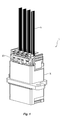
FIG. 6A is a top perspective view of a plug and ferrule holders according to the present invention;
FIG. 6B is a bottom perspective view of the plug and ferrule holders of FIG. 6A;
FIG. 6C is a front elevational view of the plug and ferrule holders of FIG. 6A;
FIG. 7A is a partial cross sectional view of a portion of a ferrule holder of FIG. 5;
FIG. 7B is a partial cross sectional view of a portion of the center portion of the adapter;
FIG. 8 is a cross sectional view of the adapter assembly in the center of the adapter assembly; and
FIG. 9 is a cross sectional view of the adapter assembly through a ferrule holder and ferrule.
DETAILED DESCRIPTION OF THE PREFERRED EMBODIMENTS
Reference will now be made in detail to the present preferred embodiment(s) of the invention, examples of which are illustrated in the accompanying drawings. Whenever possible, the same reference numerals will be used throughout the drawings to refer to the same or like parts.
Referring to FIGS. 1 and 2, one embodiment of an adapter assembly 10 is illustrated. The adapter assembly 10 includes an adapter 100, a plug 200 and a ferrule holder 300. The adapter assembly 10 is used to align ferrules 12 to other ferrules in a tightly controlled manner and in a tighter space than has been possible before. The ferrules 12 are typically multi-fiber ferrules, particularly MT type ferrules, but the present invention may include other types of ferrules. The ferrules 12 are disposed within the ferrule holder 300 and have optical fibers 14 secured therein, which may be loose optical fibers, ribbonized optical fibers, or optical fibers in any other configuration. The ferrules 12 are resiliently held in the ferrule holders 300 using a spring push 16 that engages a spring 18. The spring 18 then presses on a pin keeper 20, as is known in the art, to bias the ferrules 12 forward in the ferrule holder 300. As is described in more detail below, the ferrules 12 are held somewhat loosely within the ferrule holder 300 so that they can move relative to the ferrule holder 300 to align with other ferrules 12 that are inserted in the adapter 100 from the other side. Similarly, the ferrule holders 300 are inserted into the plug 200 and they are also loosely held in the plug 200. That is, there is typically more than 100 microns of movement in the x and y directions (See FIG. 4.) available to the ferrule holder 300 in the plug 200, as explained in more detail below.
As illustrated in FIGS. 5A-C, the ferrule holder 300 has a main body 302 with a central opening 304 that extends from a first end 306 to a second end 308 to house the fiber optic ferrules 12. The first end 306 has an opening 310 therein to allow access to the ferrule 12. The ferrule 12 may or may not exit the main body 302. That is, the ferrule 12 may extend beyond the main body 302 as shown in the figures or it may be flush with the first end 306. second end 308 allows for the optical fibers 14 (shown in FIGS. 5A and 5B to have a boot and a covering) to exit the ferrule holder 300. The ferrule holder 300 has a top surface 312 and a bottom surface 314, with a cantilevered latch 316 to engage the plug 200. The top surface 312 has a projection 320 and the bottom surface 314 has a projection 322. The projections 320,322 are preferably elongated and have a chamfered front end. The projections 320,322 are used to engage grooves in the plug 200 and the adapter 100 to position the ferrule holders 300 with precision in the adapter 100. The projection 320 has a width that is different that the width of projection 322 so as to act as a key in inserting the ferrule holder 300 in the plug 200. While the projection 320 is wider than projection 322, it could be opposite in that projection 320 is more narrow than projection 322. The projections 320,322 are preferably on the top and the bottom surfaces 312,314 of the ferrule holder 300 to allow, as illustrated below, more ferrule holders to be inserted into the adapter 100 and the plug 200. The projections 320,322 are used to position the ferrules 12 in the adapter in the x and y directions, eliminating the need for side walls to position the ferrule holders 300 and the ferrules 12.
The plug 200 will now be described relative to FIGS. 6A-6C. The plug 200 has an outside surface 202 and an inside surface 204. The inside surface 204 defines an opening 206 therethrough to allow the ferrule holders 300 to be inserted therein. The inside surface 204 has a plurality of grooves 208 on a top side 210 and a corresponding plurality of grooves 212 on the bottom side 214. The grooves 208 and 212 are dimensioned to accept the projections 320,322 from the ferrule holders 300. It should be noted that the ferrule holders 300 are adjacent to one another, that is side-by-side without any material from the plug 200 therebetween. Applicant means that by using the term adjacent herein, there is no structure that comes between the neighboring ferrule holders 300.
The outside surface 202 also has a projection 220 on the top of the plug 200, seen in FIG. 6A, and also a projection 222 on the bottom of the plug 200, seen in FIG. 6B. Again, as with the projections 320,322, projection 220 has a width that is different that the width of projection 222 so as to act as a key in inserting the plug 200 into the adapter 100. While the projection 220 is narrower than projection 222, it could be opposite in that projection 220 is wider than projection 222.
The plug 200 also has two cantilevered latches 230 on the sides to engage corresponding structure on the adapter 100. There are also latch receptacles 232 on the top side of the plug 200 to engage the latches 316 of the ferrule holders 300.
As noted above, the grooves 208 and 212 in plug 200 are dimensioned to accept the projections 320,322 from the ferrule holders 300. There is sufficient movement in the ferrule holders 300 relative to the plug 200 that when the plug 200 and ferrule holders 300 as assembled is inserted into the adapter 100, that the ferrule holders 300 can move to allow the projections 320,322 from the ferrule holders 300 to engage corresponding grooves in the adapter 100 as described below in more detail.
Returning to FIGS. 3 and 4, the adapter 100 is illustrated in more detail. The adapter 100 has a main body 102 with an opening 104 extending between a first side 106 and a second side 108. The first side 106 and a second side 108 are separated by a central portion 110. The first side 106 has a top surface 112 and a bottom surface 114. The top surface 112 has a groove 116 and the bottom surface 114 has a groove 118. The grooves 116,118 correspond to the projections 220,222 from the plug 200. The location of the wider groove in the adapter 100 will correspond with the wider projection on the plug 200.
The adapter has the center portion 110. Center portion 110 preferably has a wall 130 that extends across the opening 104 in the adapter 100 and divides the center portion 110 in half. The center portion 110 also has a raised bottom portion 132 and a dropped top portion 134 that narrows the opening 104 in the center portion 110. The wall 130 preferably extends from the raised bottom portion 132 and a dropped top portion 134 or it may be excluded completely if there is no EMI concerns with the adapter 100. The wall 130 has a plurality of openings 136 that are sized to allow the ferrules 12 to pass therethrough to engage a corresponding ferrule 12. As noted above, if the ferrules 12 only extend to the end of the ferrule holder 330, then the openings 136 should be sized to allow the ferrule holders to also extend therethrough. The adapter 100 may also have an elastomeric gasket 150 that encircles an external surface of the adapter 100 to provide EMI shielding.
The raised bottom portion 132 and a dropped top portion 134 also have a plurality of grooves 140, 142, respectively, that extend completely across the central portion 110. The grooves 140, 142 are like those in the plug 200, in that they are to engage the projections 320,322 from the ferrule holders 300. The grooves 140,142 preferably extend completely across the center portion 110 as they are formed with the same insert in the mold. Therefore, the grooves 140,142 are sure to align the ferrule holders 300 on each side of the adapter 100 as they are inserted into the adapter 100.
As the plug 200 with the ferrule holders 300 positioned therein are inserted into the adapter 100, the projections 220,222 from the plug 200 engage the grooves 116,118 on the top surface 112 and the bottom surface 114 to roughly align the ferrule holders 300 with the center portion 110 and the plurality of grooves 140 in particular. Then, as the plug 200 is inserted farther into the adapter 100, the projections 320,322 from the ferrule holders 300 engage plurality of grooves 140, 142 to align the ferrule holders 300 with the adapter and the openings 136 in the wall 130. When a plug 200 is inserted on the second side, the ferrules in the ferrule holders on the other side will be in alignment with the first side.
The position of the ferrule holders 300 on the first side 106 of the adapter relative to the ferrule holders 300 on the second side 108 is what allows the optical ferrules to be aligned with one another. There is no need, as discussed above, to worry about the stacking of tolerances as in the prior art. The positioning of the projections 320,322 on the ferrule holders 300 relative to the plurality of grooves 140, 142 is important. With reference to FIGS. 7A and 7B, the projections 320,322 are used to control the x and y locations of the ferrule holders 300. The surfaces 350 of the projections 320,322 (FIG. 7A) align with the surfaces 150 in the adapter (FIG. 7B) to control the x direction of the ferrule holder 300 relative to the adapter 100. The surfaces 352 of the ferrule holder 300 align with the surfaces 352 of the raised bottom portion 132 and the dropped top portion 134 of the center portion 110 to control the y direction of the ferrule holder 300 relative to the adapter 100. The surfaces of the projections 320,322 could also align in the y direction, given that they are parallel to the surfaces 352.
A cross section of the adapter assembly 10 is illustrated in FIG. 8 through the center of the adapter assembly. This illustrates the projections 220,200 in the openings 116,118 of the adapter 100. FIG. 9 is a cross sectional view of the adapter assembly 10 through a ferrule holder and ferrule illustrating the engagement of the projections 320,322 in the openings 140, 142.
It will be apparent to those skilled in the art that various modifications and variations can be made to the present invention without departing from the spirit and scope of the invention. Thus it is intended that the present invention cover the modifications and variations of this invention provided they come within the scope of the appended claims and their equivalents.

Claims (8)

We claim:
1. An adapter assembly for aligning one plurality of optical ferrules to another plurality of optical ferrules comprising:
an adapter having an opening extending between a first side and a second side, the adapter having a plurality of grooves in the opening and extending in a direction from the first side to the second side;
a plurality of ferrule holders, each of the plurality of ferrule holders having a central opening extending from a first end to a second end to resiliently retain a fiber optic ferrule therein, each of the plurality of ferrule holders having an opening in first end and in communication with the central opening, the second end opposite the first end and through which optical fibers extend, each of the plurality of ferrule holders having a projection on opposite outside surfaces to engage a corresponding groove in the adapter; and
a plug having an outside surface and an inside surface, the inside surface defining an opening through the plug to hold the plurality of ferrule holders therein adjacent one another, the plug having grooves in the inside surface to engage the projections from the plurality of ferrule holders to align and orient the ferrule holders in the plug.
2. The adapter assembly according to claim 1, wherein the outside of the plug has at least one projection to engage a groove in the opening in the adapter to align the plug in the opening in the adapter.
3. The adapter assembly according to claim 2, wherein the projection on the outside of the plug engages the groove in the adapter before the projections on the plurality of ferrule holders engage the plurality of grooves in the adapter.
4. The adapter assembly according to claim 1, wherein the grooves act as a keyway.
5. The adapter assembly according to claim 1, wherein the opening has a central portion between the first side and the second side, the opening in the central portion being smaller than the opening in the first side and the second side, the plurality of grooves including a first groove in a top surface and a second groove in a bottom surface of both the first and second sides and a first plurality of grooves in a top surface and a second plurality of grooves in a bottom surface of the central portion.
6. The adapter assembly according to claim 5, wherein the first groove is configured to engage a first projection on the plug and the second groove is configured to engage a second projection on the plug.
7. The adapter assembly according to claim 5, wherein the first and second plurality of grooves extend across the central portion.
8. The adapter assembly according to claim 5, wherein the first grove in the top surface and the second groove in the bottom surface extend completely through the opening.
US14/214,931 2013-03-15 2014-03-15 Alignment adapter and alignment design for a connector therefor Active 2035-06-26 US9857538B2 (en)

Priority Applications (7)

Application Number Priority Date Filing Date Title
US14/214,931 US9857538B2 (en) 2013-03-15 2014-03-15 Alignment adapter and alignment design for a connector therefor
US15/855,750 US10156684B2 (en) 2013-03-15 2017-12-27 Alignment adapter and alignment design for a connector therefor
US15/855,788 US10712509B2 (en) 2013-03-15 2017-12-27 Alignment adapter and alignment design for a connector therefor
US16/214,317 US10890723B2 (en) 2013-03-15 2018-12-10 Alignment adapter and alignment design for a connector therefor
US17/145,864 US11385415B2 (en) 2013-03-15 2021-01-11 Alignment adapter and alignment design for a connector therefor
US17/857,300 US20220357525A1 (en) 2013-03-15 2022-07-05 Alignment Adapter and Alignment Design for a Connector Therefor
US18/483,949 US11880075B1 (en) 2013-03-15 2023-10-10 Alignment adapter and alignment design for a connector therefor

Applications Claiming Priority (2)

Application Number Priority Date Filing Date Title
US201361789499P 2013-03-15 2013-03-15
US14/214,931 US9857538B2 (en) 2013-03-15 2014-03-15 Alignment adapter and alignment design for a connector therefor

Related Child Applications (2)

Application Number Title Priority Date Filing Date
US15/855,750 Division US10156684B2 (en) 2013-03-15 2017-12-27 Alignment adapter and alignment design for a connector therefor
US15/855,788 Continuation US10712509B2 (en) 2013-03-15 2017-12-27 Alignment adapter and alignment design for a connector therefor

Publications (2)

Publication Number Publication Date
US20160161680A1 US20160161680A1 (en) 2016-06-09
US9857538B2 true US9857538B2 (en) 2018-01-02

Family

ID=56094163

Family Applications (7)

Application Number Title Priority Date Filing Date
US14/214,931 Active 2035-06-26 US9857538B2 (en) 2013-03-15 2014-03-15 Alignment adapter and alignment design for a connector therefor
US15/855,750 Active US10156684B2 (en) 2013-03-15 2017-12-27 Alignment adapter and alignment design for a connector therefor
US15/855,788 Active US10712509B2 (en) 2013-03-15 2017-12-27 Alignment adapter and alignment design for a connector therefor
US16/214,317 Active US10890723B2 (en) 2013-03-15 2018-12-10 Alignment adapter and alignment design for a connector therefor
US17/145,864 Active US11385415B2 (en) 2013-03-15 2021-01-11 Alignment adapter and alignment design for a connector therefor
US17/857,300 Pending US20220357525A1 (en) 2013-03-15 2022-07-05 Alignment Adapter and Alignment Design for a Connector Therefor
US18/483,949 Active US11880075B1 (en) 2013-03-15 2023-10-10 Alignment adapter and alignment design for a connector therefor

Family Applications After (6)

Application Number Title Priority Date Filing Date
US15/855,750 Active US10156684B2 (en) 2013-03-15 2017-12-27 Alignment adapter and alignment design for a connector therefor
US15/855,788 Active US10712509B2 (en) 2013-03-15 2017-12-27 Alignment adapter and alignment design for a connector therefor
US16/214,317 Active US10890723B2 (en) 2013-03-15 2018-12-10 Alignment adapter and alignment design for a connector therefor
US17/145,864 Active US11385415B2 (en) 2013-03-15 2021-01-11 Alignment adapter and alignment design for a connector therefor
US17/857,300 Pending US20220357525A1 (en) 2013-03-15 2022-07-05 Alignment Adapter and Alignment Design for a Connector Therefor
US18/483,949 Active US11880075B1 (en) 2013-03-15 2023-10-10 Alignment adapter and alignment design for a connector therefor

Country Status (1)

Country Link
US (7) US9857538B2 (en)

Cited By (4)

* Cited by examiner, † Cited by third party
Publication number Priority date Publication date Assignee Title
US11112566B2 (en) * 2018-03-19 2021-09-07 Senko Advanced Components, Inc. Removal tool for removing a plural of micro optical connectors from an adapter interface
US20220107467A1 (en) * 2019-01-30 2022-04-07 US Conec, Ltd Small form factor connector and adapter
US11506848B2 (en) 2017-12-19 2022-11-22 Us Conec Ltd. Mini duplex connector with push-pull polarity mechanism and carrier using rail receiving portions
US20230161113A1 (en) * 2015-12-19 2023-05-25 Us Conec Ltd. Field Changeable Fiber Optic Connector Polarity Keying

Families Citing this family (7)

* Cited by examiner, † Cited by third party
Publication number Priority date Publication date Assignee Title
US9857538B2 (en) * 2013-03-15 2018-01-02 Us Conec, Ltd. Alignment adapter and alignment design for a connector therefor
EP3167321B1 (en) 2014-07-07 2020-09-02 Commscope Technologies LLC Optical ferrule for multi-fiber cable and hardened multi-fiber optic connector therefore
US10670824B2 (en) 2015-04-02 2020-06-02 Commscope Technologies Llc Fiber optic network architecture using high fiber-count fiber optic connectors
US11333836B2 (en) 2017-01-30 2022-05-17 Senko Advanced Components, Inc. Adapter for optical connectors
EP3677938B1 (en) * 2017-12-28 2023-07-12 Fujikura Ltd. Optical connector and method for connecting optical connector
US11199669B1 (en) * 2020-09-24 2021-12-14 Hewlett Packard Enterprise Development Lp Modular faceplate optical sub-assembly
WO2023188290A1 (en) * 2022-03-31 2023-10-05 住友電気工業株式会社 Optical connection structure, adaptor and optical connector

Citations (3)

* Cited by examiner, † Cited by third party
Publication number Priority date Publication date Assignee Title
US5129024A (en) * 1990-08-22 1992-07-07 Yamaichi Electric Co., Ltd. Optical connector in which a cable holder is accommodated within a connector housing
US6331079B1 (en) * 1999-12-07 2001-12-18 Molex Incorporated Mounting system for a connector assembly to a substrate
US20110091158A1 (en) * 2008-03-03 2011-04-21 Furukawa Electric Co., Ltd. Connector unit

Family Cites Families (21)

* Cited by examiner, † Cited by third party
Publication number Priority date Publication date Assignee Title
US4645295A (en) * 1980-02-04 1987-02-24 Allied Corporation Fiber optic connector
US5121454A (en) 1989-11-24 1992-06-09 Nippon Telegraph And Telephone Corporation Optical connector
US5537501A (en) 1989-11-24 1996-07-16 Nippon Telegraph And Telephone Corporation Optical connector
NL1003147C2 (en) * 1996-05-17 1997-11-18 Framatome Connectors Belgium Backpanel connector system.
US6095695A (en) * 1996-10-28 2000-08-01 Sumitomo Electric Industries, Ltd. Optical connector, and using method and tool thereof
DE19728960C1 (en) * 1997-06-30 2000-07-06 Siemens Ag Optical multiple connector
US6406192B1 (en) * 1999-12-07 2002-06-18 Molex Incorporated Connector assembly floating mount
US6361218B1 (en) * 1999-12-07 2002-03-26 Molex Incorporated Fiber optic connector module
US6568861B2 (en) * 2001-05-16 2003-05-27 Fci Americas Technology, Inc. Fiber optic adapter
US6764222B1 (en) 2003-01-16 2004-07-20 Molex Incorporated Fiber optic connector assembly
JP2004354693A (en) 2003-05-29 2004-12-16 Suncall Corp Optical connector
US7008117B2 (en) 2003-12-23 2006-03-07 Amphenol Corporation Optical connector assembly with features for ease of use
US20050281509A1 (en) * 2004-06-18 2005-12-22 3M Innovative Properties Company Optical connector system with EMI shielding
US20080131055A1 (en) * 2006-12-04 2008-06-05 Parkman L Edward Keyed push-pull type fiber optic connection system
US9366829B2 (en) * 2010-03-16 2016-06-14 Ofs Fitel, Llc Multi-ferrule connector for multicore fiber terminations
JP5501166B2 (en) * 2010-09-03 2014-05-21 株式会社フジクラ Optical connector and optical communication system
JP2015500517A (en) 2011-12-27 2015-01-05 矢崎総業株式会社 Optical module
CN202600189U (en) * 2012-05-31 2012-12-12 泰科电子(上海)有限公司 Adapter assembly and connector assembly
US9086546B2 (en) * 2012-11-29 2015-07-21 Corning Cable Systems Llc Connector systems having receptacle assembly and plug assembly
US20140241689A1 (en) * 2013-02-28 2014-08-28 Corning Cable Systems Llc Ganged fiber optic connector adapter modules and assemblies having reinforcement members and staggered fiber optic connector adapter ports
US9857538B2 (en) * 2013-03-15 2018-01-02 Us Conec, Ltd. Alignment adapter and alignment design for a connector therefor

Patent Citations (3)

* Cited by examiner, † Cited by third party
Publication number Priority date Publication date Assignee Title
US5129024A (en) * 1990-08-22 1992-07-07 Yamaichi Electric Co., Ltd. Optical connector in which a cable holder is accommodated within a connector housing
US6331079B1 (en) * 1999-12-07 2001-12-18 Molex Incorporated Mounting system for a connector assembly to a substrate
US20110091158A1 (en) * 2008-03-03 2011-04-21 Furukawa Electric Co., Ltd. Connector unit

Cited By (12)

* Cited by examiner, † Cited by third party
Publication number Priority date Publication date Assignee Title
US20230161113A1 (en) * 2015-12-19 2023-05-25 Us Conec Ltd. Field Changeable Fiber Optic Connector Polarity Keying
US11789212B2 (en) * 2015-12-19 2023-10-17 Us Conec Ltd. Field changeable fiber optic connector polarity keying
US11506848B2 (en) 2017-12-19 2022-11-22 Us Conec Ltd. Mini duplex connector with push-pull polarity mechanism and carrier using rail receiving portions
US11525965B2 (en) 2017-12-19 2022-12-13 Us Conec Ltd. Mini duplex connector with push-pull polarity mechanism and carrier with latch and rail
US20230288650A1 (en) * 2017-12-19 2023-09-14 Us Conec Ltd. Mini duplex connector with push-pull polarity mechanism and carrier with latch and rail
US11808994B1 (en) * 2017-12-19 2023-11-07 Us Conec Ltd. Mini duplex connector with push-pull polarity mechanism and carrier
US20230358974A1 (en) * 2017-12-19 2023-11-09 Us Conec Ltd. Mini duplex connector with push-pull polarity mechanism and carrier
US11846813B2 (en) 2017-12-19 2023-12-19 Us Conec Ltd. Mini duplex connector with push-pull polarity mechanism and carrier with latch and rail
US11112566B2 (en) * 2018-03-19 2021-09-07 Senko Advanced Components, Inc. Removal tool for removing a plural of micro optical connectors from an adapter interface
US20220107467A1 (en) * 2019-01-30 2022-04-07 US Conec, Ltd Small form factor connector and adapter
US20230400642A1 (en) * 2019-01-30 2023-12-14 Us Conec, Ltd. Small form factor connector and adapter
US11940654B2 (en) * 2019-01-30 2024-03-26 Us Conec, Ltd. Small form factor connector and adapter

Also Published As

Publication number Publication date
US20180106973A1 (en) 2018-04-19
US20220357525A1 (en) 2022-11-10
US20190107679A1 (en) 2019-04-11
US11385415B2 (en) 2022-07-12
US10890723B2 (en) 2021-01-12
US10712509B2 (en) 2020-07-14
US20160161680A1 (en) 2016-06-09
US11880075B1 (en) 2024-01-23
US20210255403A1 (en) 2021-08-19
US20180120519A1 (en) 2018-05-03
US20240036271A1 (en) 2024-02-01
US10156684B2 (en) 2018-12-18

Similar Documents

Publication Publication Date Title
US11385415B2 (en) Alignment adapter and alignment design for a connector therefor
US11886017B2 (en) Multiports and other devices having connection ports with securing features and methods of making the same
US11573386B2 (en) Fiber optic connector assembly, apparatus for forming a transceiver interface, and ferrule
US9632256B2 (en) Optical fiber adapter with shutter member
US5613025A (en) Adapter assembly for fiber optic connectors
US8870468B2 (en) Multi-port shielded adapter
JP7057551B2 (en) Connector system
US20120141070A1 (en) Connector assembly with improved structure on a bracket for mounting connectors
JP2008046146A (en) Adapter for optical connector interconnection
US20150362682A1 (en) Optical fiber interconnect assembly
US10371903B1 (en) Spacers for use in a fiber optic connector
US20210103099A1 (en) Fiber optic terminals and fiber optic networks having variable ratio couplers
US20130094815A1 (en) Optical fiber connector and adapter capable of preventing dust
TWI730349B (en) Optical fiber adapter
JP7282501B2 (en) Adapter with LC type 2-core shutter
US20030053760A1 (en) Optical connector system
US20240004155A1 (en) Cassette case with integrated adapter for optical connector
US20050058401A1 (en) Keyed adapter and connector
WO2018042775A1 (en) Optical connection structure
JP2023084257A (en) Optical connector and optical connection structure
JP2018081229A (en) Adapter for optical connector interconnection
KR20140001151A (en) Optical loopback connector
JP2013218107A (en) Adapter for optical connector interconnection

Legal Events

Date Code Title Description
AS Assignment

Owner name: US CONEC, LTD., NORTH CAROLINA

Free format text: ASSIGNMENT OF ASSIGNORS INTEREST;ASSIGNORS:NGUYEN, HIEP;CHILDERS, DARRELL R.;HUGHES, MICHAEL E.;AND OTHERS;SIGNING DATES FROM 20140728 TO 20140826;REEL/FRAME:033643/0978

STCF Information on status: patent grant

Free format text: PATENTED CASE

FEPP Fee payment procedure

Free format text: SURCHARGE FOR LATE PAYMENT, LARGE ENTITY (ORIGINAL EVENT CODE: M1554); ENTITY STATUS OF PATENT OWNER: LARGE ENTITY

MAFP Maintenance fee payment

Free format text: PAYMENT OF MAINTENANCE FEE, 4TH YEAR, LARGE ENTITY (ORIGINAL EVENT CODE: M1551); ENTITY STATUS OF PATENT OWNER: LARGE ENTITY

Year of fee payment: 4