EP1258418A1 - Fixation for two adjacent body elements - Google Patents
Fixation for two adjacent body elements Download PDFInfo
- Publication number
- EP1258418A1 EP1258418A1 EP02291193A EP02291193A EP1258418A1 EP 1258418 A1 EP1258418 A1 EP 1258418A1 EP 02291193 A EP02291193 A EP 02291193A EP 02291193 A EP02291193 A EP 02291193A EP 1258418 A1 EP1258418 A1 EP 1258418A1
- Authority
- EP
- European Patent Office
- Prior art keywords
- fixing
- adjacent
- arrangement according
- vehicle
- common
- Prior art date
- Legal status (The legal status is an assumption and is not a legal conclusion. Google has not performed a legal analysis and makes no representation as to the accuracy of the status listed.)
- Granted
Links
Images


Classifications
-
- B—PERFORMING OPERATIONS; TRANSPORTING
- B62—LAND VEHICLES FOR TRAVELLING OTHERWISE THAN ON RAILS
- B62D—MOTOR VEHICLES; TRAILERS
- B62D29/00—Superstructures, understructures, or sub-units thereof, characterised by the material thereof
- B62D29/04—Superstructures, understructures, or sub-units thereof, characterised by the material thereof predominantly of synthetic material
- B62D29/048—Connections therefor, e.g. joints
-
- B—PERFORMING OPERATIONS; TRANSPORTING
- B60—VEHICLES IN GENERAL
- B60R—VEHICLES, VEHICLE FITTINGS, OR VEHICLE PARTS, NOT OTHERWISE PROVIDED FOR
- B60R19/00—Wheel guards; Radiator guards, e.g. grilles; Obstruction removers; Fittings damping bouncing force in collisions
- B60R19/02—Bumpers, i.e. impact receiving or absorbing members for protecting vehicles or fending off blows from other vehicles or objects
- B60R19/24—Arrangements for mounting bumpers on vehicles
- B60R2019/245—Arrangements for mounting bumpers on vehicles with adjusting means to compensate manufacturing tolerances, e.g. between bumper and energy absorbers
-
- B—PERFORMING OPERATIONS; TRANSPORTING
- B60—VEHICLES IN GENERAL
- B60R—VEHICLES, VEHICLE FITTINGS, OR VEHICLE PARTS, NOT OTHERWISE PROVIDED FOR
- B60R19/00—Wheel guards; Radiator guards, e.g. grilles; Obstruction removers; Fittings damping bouncing force in collisions
- B60R19/02—Bumpers, i.e. impact receiving or absorbing members for protecting vehicles or fending off blows from other vehicles or objects
- B60R19/24—Arrangements for mounting bumpers on vehicles
- B60R2019/247—Fastening of bumpers' side ends
Definitions
- the invention relates to an attachment arrangement for two adjacent bodywork elements.
- the invention relates more particularly to an arrangement for fixing first and second adjacent elements bodywork and / or trim on a structural body element of the vehicle.
- each side end of the shield front is connected to a structural element by a first piece intermediate such as a fastening bridge.
- each front fender is fixed on a second intermediate piece which allows their assembly with the vehicle body.
- Such an arrangement then requires two first and two second intermediate pieces to fix the front bumper as well that the two front wings right and left on the structure of the vehicle.
- the four different intermediate pieces must be individually designed, manufactured, stored and managed which causes high costs.
- first and second symmetrical intermediate pieces that can be used indifferently to the left and to the right of the vehicle. This allows to reduce part of the design, manufacturing and storage.
- such parts have a part central on each side of which can be, for example, attach a right or left wing.
- This conception allows good accessibility of the wing fixing means or the front bumper on the central part, but the rigidity of the intermediate piece is not sufficient.
- the assembly front fenders and bumper requires handling and fixing of four intermediate parts on elements of vehicle structure. This increases the number of operations as well that assembly time.
- the invention offers a fixing arrangement for a first and a second adjacent bodywork and / or trim elements on an element structural body of the vehicle, characterized in that it comprises a common fixing piece for assembling and fixing the first and second element with respect to the structure of the vehicle.
- a common fixing piece 10 is oriented along an axis coordinate system X'-X 'and Z'-Z' which is offset angularly with respect to the horizontal axis Y-Y by an angle ⁇ .
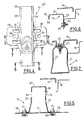
- Figure 1 shows a schematic view of the front of a motor vehicle, and in particular a utility vehicle.
- the common fastener 10 is fixed to a wall of an element structural 12 of the vehicle body which is oriented substantially vertically and which is turned towards a lateral side of the vehicle.
- the structural element 12 can be, for example, a lining of front foot.
- the structural element 12 of the vehicle body can be connected to a spar or cross member of the body by a process such as welding.
- a front shield 14 forming a "bumper" as well as a wing before 16, here the left front wing, are connected, for example, by a screw connection to the common fastener 10.
- the part of the common fastener 10, in accordance with Figures 2 to 4, has a side back 20 which connects two flanges transverse front 22 and rear 24 which are each connected to a front longitudinal foot 26 and rear foot 28 respectively.
- the longitudinal legs 26 and 28 extend in a plane substantially perpendicular to the Y-Y axis. They each include a fixing zone with the structural element 12 in each which a hole 30 is made.
- Figure 5 shows a section which crosses diametrically the holes 30.
- the holes 30 allow the passage of first means of fixing 31 such as an assembly of the screw-nut type so as to keep the longitudinal feet in a determined position 26, 28 relative to the structural element 12.
- the diameter of the holes 30 is greater to the diameter of the first fixing means 31 by which they are crossed.
- the position of the part fixing joint 10 can be adjusted before tightening the fastening means 31.
- transverse flanges 22 and 24 and the lateral back 20 forms an element which presents in section, a shape of U overturned (see Figure 5).
- transverse flanges 22, 24 extend in planes perpendicular to the one containing the longitudinal feet 26, 28.
- the design of the common fastener 10 allows to use this single piece 10 either on the right side or on the left side of the vehicle to fix either the right part of the shield front 14 and the right front wing, the left part of the shield forward 14 and the left front fender 16.
- the rear transverse flange 24 is consisting of a first part 40 of substantially shaped rectangular with an end stop 42 connected to the back lateral 20 and of which an intermediate stop 44 is connected to a second part 46 of truncated triangular shape to which is connected the rear longitudinal leg 28.
- the first part 40 comprises, near each of its upper and lower ends, a fixing hole 48 upper and lower respectively, which allows the passage of a fastening element, such as a screw, of second means of attachment 50.
- Figure 5 is a section along line 5-5 which goes through the center of the lower mounting hole 48.
- the second fixing means 50 make it possible to keep the left front wing in position 16.
- the diameter of the holes 48 is greater to the diameter of the second fastening means 50 by which they are crossed.
- the position of the wing front left 16 with respect to the common fixing piece 10 can be adjusted before tightening the second means of fixing 50.
- the rear transverse flange 24 has in the center of its first part 40 a recess 52 including a cross section is shown in Figure 5.
- the recess 52 allows, during assembly, passage of a guide tongue 54 of the wing front left 16 so as to hold these two pieces one by relation to each other before their fixation by the second means of fixing 50.
- the rear transverse flange 24 also comprises two passage means 56 whose centers are substantially aligned along the longitudinal axis X'-X 'with the centers of the attachment 58 made in the transverse flange 22.
- the passage means 56 allow the passage of a fixing tool, such as a pneumatic screwdriver, for fixing of the right wing on the front transverse flange 22. They facilitate thus access to attachment means, not shown, of the wing front right on the front transverse flange 22.
- the front transverse flange 22 is consisting of a first part 60 and a second part 62.
- the second parts 46 and 62 of the transverse flanges rear 24 and front 22 respectively allow the back to be oriented lateral 20 around the axis X'-X 'so that it is substantially parallel to the area of the inner face of the front shield 14 which is located near the common fixing part 10.
- the first part 60 comprises, in addition to the fixing holes 58, a straight recess 64.
- the front transverse flange 22 includes means for passage 66, such as a notch, which are located near each of its upper and lower ends. Ways passage 66 are aligned with the fixing holes 48 according to the longitudinal axis X'-X '. They allow, when fixing the wing front left 16 on the rear transverse flange 24, the passage a fixing tool, they facilitate access to the second fastening means 50.
- the two front transverse flanges 22 and rear 24 are connected by a reinforcing plate 68 which extends in a plane substantially parallel to the plane defined by the axes X'-X 'and Y-Y.
- the reinforcement plate 68 increases the rigidity of the part fixing joint 10.
- the lateral back 20 comprises holding means 70 which are crossed by section 7-7 shown in Figure 7.
- the holding means 70 allow the passage of the third fastening means 72 such as a screw-nut type assembly which cooperates with a specific area of the front shield 14.
- the holding means 70 are made so that, during assembly, they extend in a plane substantially parallel to the determined area of the front shield 14.
- the holding means 70 can be produced by stamping of the lateral back 20.
- the means of holding 70 allow, when mounting the front shield 14 on the common fixing part 10, the adjustment of the position of these two pieces relative to each other. To this end, when the holding means 70 have a hole, the diameter of this hole is greater than the diameter of the third fastening means 72.
- the common fixing piece 10 has reinforcing ribs 74 which extend on the one hand on the front transverse flange 22 and on the longitudinal foot front 26 and, on the other hand, on the rear transverse flange 24 and on the rear longitudinal leg 28.
- the rigidity of the part fixing joint 10 is increased which increases its resistance mechanical and reinforces the attachment of the front fenders and the shield before 14 on the vehicle structure.
- the common fixing piece 10 allows the fixing of the front shield 14 and a front wing which can be indifferently the right wing or the left wing of the vehicle and only one model of part is required for each type of vehicle. So the design, manufacturing, management and storage costs of the common fixing piece 10 are greatly reduced by cost of two or four pieces required before.
- the common fixing piece 10 which can be used indifferently for the assembly of the left front wing 16 or the right front wing, it will only be described in the following description that the assembly of the common part 10 of the left front wing, on the left side of the vehicle.
- the guide tongue 54 of the left front fender 16 is slid into the left recess 52, this which allows the maintenance of the common part 10 on the front wing left 16. So these two pieces are manipulated simultaneously.
- the left front wing 16 is then brought into position by compared to other elements constituting the vehicle such as the front door and the passage of the front wheel.
- the common part of attachment 10 can be moved slightly so that the holes 30 and the holes 48 correspond to the orifices made in the structural element 12 and the front wing 16 respectively. it thus allows the passage of the first 31 and second 50 fixing means which are then tightened so as to immobilize the left front wing 16 relative to the structural element 12, by through the common fixing piece 10.
- the means of passage 54 offer easy access to the second means of fixing 50.
- the front shield 14 is attached to the vehicle, it is positioned, for example, in relation to the front fenders and the grille. Then the third fastening means 72 cooperate with the holding means 70 for fixing the front shield by report to the vehicle body.
- This assembly makes it easy to position and with precision the front bumper 16 and the front fenders of the vehicle by relation to other elements and / or covering such as front doors, the engine hood, etc., ensuring compliance with style and appearance constraints, such as the existence of clearances that are determined between the edges of two adjacent body components such as a front fender and the corresponding front door.
- this assembly is carried out with the part fixing joint 10 which is used interchangeably on the side right and left side of the vehicle, thereby reducing on the one hand the costs related to the use of multiple parts, such as the costs of design, manufacturing, management and, secondly, the time to mounting on the vehicle.
Landscapes
- Engineering & Computer Science (AREA)
- Mechanical Engineering (AREA)
- Architecture (AREA)
- Structural Engineering (AREA)
- Chemical & Material Sciences (AREA)
- Combustion & Propulsion (AREA)
- Transportation (AREA)
- Body Structure For Vehicles (AREA)
Abstract
L'invention propose un agencement pour la fixation d'un premier (16) et d'un second (14) éléments adjacents de carrosserie et/ou d'habillage sur un élément structurel (12) de caisse d'un véhicule automobile, caractérisé en ce qu'il comporte une pièce commune de fixation (10) pour l'assemblage et la fixation du premier (16) et du second (14) éléments par rapport à la structure du véhicule. <IMAGE>The invention provides an arrangement for fixing a first (16) and a second (14) adjacent bodywork and / or trim elements on a structural element (12) of the body of a motor vehicle, characterized in that it comprises a common fixing part (10) for assembling and fixing the first (16) and the second (14) elements relative to the structure of the vehicle. <IMAGE>
Description
L'invention concerne un agencement de fixation de deux éléments adjacents de carrosserie.The invention relates to an attachment arrangement for two adjacent bodywork elements.
L'invention concerne plus particulièrement un agencement de fixation d'un premier et d'un second éléments adjacents carrosserie et/ou d'habillage sur un élément structurel de caisse du véhicule.The invention relates more particularly to an arrangement for fixing first and second adjacent elements bodywork and / or trim on a structural body element of the vehicle.
Il est connu de fixer les éléments de carrosserie et/ou d'habillage sur un élément structurel tel qu'une doublure de pied avant du véhicule. Ainsi, chaque extrémité latérale du bouclier avant est reliée à un élément de structure par une première pièce intermédiaire telle qu'un pontet de fixation. De façon similaire, chaque aile avant est fixée sur une seconde pièce intermédiaire qui permet leur assemblage avec la caisse du véhicule.It is known to fix the bodywork elements and / or covering on a structural element such as a foot lining front of the vehicle. So each side end of the shield front is connected to a structural element by a first piece intermediate such as a fastening bridge. In the same way, each front fender is fixed on a second intermediate piece which allows their assembly with the vehicle body.
Un tel agencement nécessite alors deux premières et deux secondes pièces intermédiaires pour fixer le bouclier avant ainsi que les deux ailes avant droite et gauche sur la structure du véhicule. Les quatre pièces intermédiaires différentes doivent être conçues, fabriquées, stockées et gérées individuellement ce qui provoque des coûts élevés.Such an arrangement then requires two first and two second intermediate pieces to fix the front bumper as well that the two front wings right and left on the structure of the vehicle. The four different intermediate pieces must be individually designed, manufactured, stored and managed which causes high costs.
Il a déjà été proposé de réaliser des première et seconde pièces intermédiaires symétriques qui peuvent être utilisées indifféremment à gauche et à droite du véhicule. Cela permet de réduire une partie des coûts de conception, de fabrication et de stockage. Cependant, de telles pièces comportent une partie centrale sur chacune des faces desquelles peut être, par exemple, fixée une aile droite ou gauche. Cette conception permet une bonne accessibilité des moyens de fixation de l'aile ou du bouclier avant sur la partie centrale, mais la rigidité de la pièce intermédiaire n'est pas suffisante. De plus, l'assemblage des ailes et du bouclier avant nécessite la manipulation et la fixation de quatre pièces intermédiaires sur des éléments de structure du véhicule. Cela augmente le nombre d'opérations ainsi que le temps de montage.It has already been proposed to perform first and second symmetrical intermediate pieces that can be used indifferently to the left and to the right of the vehicle. This allows to reduce part of the design, manufacturing and storage. However, such parts have a part central on each side of which can be, for example, attach a right or left wing. This conception allows good accessibility of the wing fixing means or the front bumper on the central part, but the rigidity of the intermediate piece is not sufficient. In addition, the assembly front fenders and bumper requires handling and fixing of four intermediate parts on elements of vehicle structure. This increases the number of operations as well that assembly time.
Dans le but de remédier à ces inconvénients, l'invention propose un agencement de fixation d'un premier et d'un second éléments adjacents carrosserie et/ou d'habillage sur un élément structurel de caisse du véhicule, caractérisé en ce qu'il comporte une pièce commune de fixation pour l'assemblage et la fixation du premier et du second élément par rapport à la structure du véhicule.In order to remedy these drawbacks, the invention offers a fixing arrangement for a first and a second adjacent bodywork and / or trim elements on an element structural body of the vehicle, characterized in that it comprises a common fixing piece for assembling and fixing the first and second element with respect to the structure of the vehicle.
Selon d'autres caractéristiques de l'invention :
- la pièce commune de fixation comprend :
- deux pieds longitudinaux qui comportent chacun une zone de fixation avec l'élément structurel de caisse ;
- deux flasques transversaux qui sont chacun solidaires d'un pied longitudinal, qui sont sensiblement parallèles entre eux et qui comportent chacun des zones de fixation du premier élément adjacent du véhicule ainsi que des moyens de passage d'un outil de fixation lors de l'assemblage du premier élément adjacent sur le flasque latéral opposé, les moyens de passage de l'outil étant sensiblement alignés avec les zones de fixation du premier élément adjacent selon une direction sensiblement perpendiculaire au flasque opposé ; et
- un dos latéral qui relie les deux flasques transversaux et qui comporte des moyens de maintien du second élément adjacent ;
- les pieds longitudinaux sont fixés sur une paroi de l'élément structurel de caisse qui est orientée vers un côté latéral du véhicule ;
- les deux flasques transversaux s'étendent dans des plans sensiblement perpendiculaires aux pieds longitudinaux ;
- au moins un flasque latéral comporte un évidement qui permet, lors de l'assemblage, le passage d'une languette de guidage du premier élément adjacent de façon à maintenir ces deux pièces l'une par rapport à l'autre, avant leur fixation :
- les moyens pour le passage d'un outil de fixation comprennent au moins une ouverture réalisée dans le flasque latéral ;
- les pieds longitudinaux et les moyens de maintien du second élément adjacent sont contenus dans deux plans sensiblement parallèles ;
- les zones de fixation des pieds longitudinaux comportent un trou dont le diamètre est supérieur au diamètre des premiers moyens de fixation avec lequel il coopère, de façon à permettre le réglage de la position de la pièce commune par rapport à l'élément structurel de caisse, avant leur fixation ;
- les zones de fixation des flasques transversaux comportent au moins un trou dont le diamètre est supérieur au diamètre des seconds moyens de fixation avec lequel il coopère, de façon à permettre le réglage de la position du premier élément adjacent par rapport à la pièce commune, avant leur fixation ;
- les moyens de maintien du second élément adjacent comportent au moins un trou dont le diamètre est supérieur au diamètre des troisièmes moyens de fixation avec lequel il coopère, de façon à permettre le réglage de la position du second élément adjacent par rapport à la pièce commune, avant leur fixation ;
- le premier élément adjacent est un bouclier avant du véhicule ;
- le second élément adjacent est une aile avant droite ou avant gauche du véhicule.
- the common fixing piece includes:
- two longitudinal legs which each have a fixing zone with the structural body element;
- two transverse flanges which are each integral with a longitudinal foot, which are substantially parallel to each other and which each comprise areas for fixing the first adjacent element of the vehicle as well as means for passing a fixing tool during assembly of the first adjacent element on the opposite lateral flange, the means for passing the tool being substantially aligned with the fixing zones of the first adjacent element in a direction substantially perpendicular to the opposite flange; and
- a lateral back which connects the two transverse flanges and which comprises means for holding the second adjacent element;
- the longitudinal legs are fixed to a wall of the structural body element which is oriented towards a lateral side of the vehicle;
- the two transverse flanges extend in planes substantially perpendicular to the longitudinal feet;
- at least one lateral flange has a recess which allows, during assembly, the passage of a guide tab of the first adjacent element so as to hold these two parts relative to each other, before their fixing:
- the means for the passage of a fixing tool comprise at least one opening made in the lateral flange;
- the longitudinal feet and the means for holding the second adjacent element are contained in two substantially parallel planes;
- the fixing zones of the longitudinal legs include a hole whose diameter is greater than the diameter of the first fixing means with which it cooperates, so as to allow the position of the common part to be adjusted relative to the structural body element, before fixing;
- the fixing zones of the transverse flanges include at least one hole whose diameter is greater than the diameter of the second fixing means with which it cooperates, so as to allow the position of the first adjacent element to be adjusted relative to the common part, before their fixation;
- the means for holding the second adjacent element comprise at least one hole whose diameter is greater than the diameter of the third fixing means with which it cooperates, so as to allow the position of the second adjacent element to be adjusted relative to the common part, before fixing;
- the first adjacent element is a front bumper of the vehicle;
- the second adjacent element is a front right or front left wing of the vehicle.
D'autres caractéristiques et avantages de l'invention apparaítront à la lecture de la description détaillée qui suit pour la compréhension de laquelle on se reportera aux figures dans lesquels :
- la figure 1 représente une vue schématique, avec arrachement partiel, du côté de l'avant d'un véhicule automobile équipé d'un agencement du bouclier avant et de l'aile avant gauche du véhicule selon l'invention ;
- la figure 2 représente en perspective la pièce commune de fixation pour l'assemblage et la fixation du bouclier avant et d'une aile avant selon l'invention ;
- la figure 3 représente une perspective similaire à celle de la figure 2 selon une orientation différente ;
- la figure 4 représente en vue de côté la pièce commune de fixation selon l'invention ;
- la figure 5 est une section selon la ligne 5-5 de la figure 4 qui représente la pièce commune fixée sur un élément de structure véhicule et sur laquelle sont agencés le bouclier avant et l'aile ;
- la figure 6 représente une section similaire à celle de la figure 5 selon la ligne 6-6 de la figure 4 ;
- la figure 7 représente une section similaire à celle de la figure 5 selon une ligne 7-7 de la figure 4.
- Figure 1 shows a schematic view, partially broken away, on the front side of a motor vehicle equipped with an arrangement of the front bumper and the left front fender of the vehicle according to the invention;
- FIG. 2 shows in perspective the common fixing part for assembling and fixing the front bumper and a front wing according to the invention;
- Figure 3 shows a perspective similar to that of Figure 2 in a different orientation;
- Figure 4 shows a side view of the common fixing part according to the invention;
- Figure 5 is a section along line 5-5 of Figure 4 which shows the common part fixed to a vehicle structural element and on which are arranged the front shield and the wing;
- Figure 6 shows a section similar to that of Figure 5 along line 6-6 of Figure 4;
- FIG. 7 represents a section similar to that of FIG. 5 along a line 7-7 of FIG. 4.
Dans la description qui va suivre, on utilisera, à titre non limitatif, des orientations longitudinale correspondant à l'axe X-X, verticale correspondant à l'axe Z-Z et transversale correspondant à l'axe Y-Y.In the description which follows, we will use, not limiting, longitudinal orientations corresponding to the X-X axis, vertical corresponding to the Z-Z axis and corresponding transverse to the Y-Y axis.
Dans l'exemple proposé, une pièce de fixation commune 10
est orientée selon un repère d'axes X'-X' et Z'-Z' qui est décalé
angulairement par rapport à l'axe horizontal Y-Y d'un angle α.In the example proposed, a
Dans la suite de la description, on considèrera que l'angle α est faible et que, ainsi, les axes X'-X' et Z'-Z' sont orientés sensiblement longitudinalement et verticalement respectivement.In the following description, we will consider that the angle α is weak and that, thus, the axes X'-X 'and Z'-Z' are oriented substantially longitudinally and vertically respectively.
La figure 1 représente une vue schématique de l'avant d'un
véhicule automobile, et notamment d'un véhicule utilitaire. La
pièce de fixation commune 10 est fixée sur une paroi d'un élément
structurel 12 de caisse du véhicule qui est orienté sensiblement
verticalement et qui est tourné vers un côté latéral du véhicule.
L'élément structurel 12 peut être, par exemple, une doublure de
pied avant. Figure 1 shows a schematic view of the front of a
motor vehicle, and in particular a utility vehicle. The
L'élément structurel 12 de caisse du véhicule peut être
relié à un longeron ou une traverse de la caisse par un procédé
tel que le soudage.The
Un bouclier avant 14 formant "pare-chocs" ainsi qu'une aile
avant 16, ici l'aile avant gauche, sont reliés, par exemple, par un
assemblage vissé à la pièce de fixation commune 10.A
La pièce de la fixation commune 10, conformément aux
figures 2 à 4, comporte un dos latéral 20 qui relie deux flasques
transversaux avant 22 et arrière 24 qui sont reliés chacun à un
pied longitudinal avant 26 et arrière 28 respectivement.The part of the
Les pieds longitudinaux 26 et 28 s'étendent dans un plan
sensiblement perpendiculaire à l'axe Y-Y. Ils comportent chacun
une zone de fixation avec l'élément structurel 12 dans chacune
desquelles un trou 30 est réalisé. La figure 5 représente une
section qui traverse diamétralement les trous 30.The
Les trous 30 permettent le passage de premiers moyens de
fixation 31 tels qu'un assemblage du type vis-écrou de façon à
maintenir dans une position déterminée les pieds longitudinaux
26, 28 par rapport à l'élément structurel 12.The
Avantageusement, le diamètre des trous 30 est supérieur
au diamètre des premiers moyens de fixation 31 par lesquels ils
sont traversés. Ainsi, lors du montage, la position de la pièce
commune de fixation 10 peut être ajustée avant le serrage des
moyens de fixation 31.Advantageously, the diameter of the
Les flasques transversaux 22 et 24 et le dos latéral 20
formes un élément qui présente en section, une forme de U
renversé (voir figure 5).The
Les flasques transversaux 22, 24 s'étendent dans des
plans perpendiculaires à celui qui contient les pieds longitudinaux
26, 28.The
La conception de la pièce de fixation commune 10 permet
d'utiliser cette pièce unique 10 indifféremment du côté droit ou du
côté gauche du véhicule pour fixer soit la partie droite du bouclier
avant 14 et l'aile avant droite, soit la partie gauche du bouclier
avant 14 et l'aile avant gauche 16.The design of the
Pour ce faire, le flasque transversal arrière 24 est
constitué d'une première partie 40 de forme sensiblement
rectangulaire dont une arrête d'extrémité 42 est reliée au dos
latéral 20 et dont une arrête intermédiaire 44 est raccordée à une
seconde partie 46 de forme triangulaire tronquée à laquelle est
connecté le pied longitudinal arrière 28.To do this, the rear
La première partie 40 comporte, à proximité de chacune de
ses extrémités supérieure et inférieure, un trou de fixation 48
supérieur et inférieur respectivement, qui permet le passage d'un
élément de fixation, tel qu'une vis, de deuxièmes moyens de
fixation 50. La figure 5 est une section selon la ligne 5-5 qui
passe par le centre du trou de fixation inférieure 48.The
Les deuxièmes moyens de fixation 50 permettent de
maintenir en position l'aile avant gauche 16.The second fixing means 50 make it possible to
keep the left front wing in
Avantageusement, le diamètre des trous 48 est supérieur
au diamètre des deuxièmes moyens de fixation 50 par lesquels ils
sont traversés. Ainsi, lors du montage, la position de la l'aile
avant gauche 16 par rapport à la pièce commune de fixation 10
peut être ajustée avant le serrage des deuxièmes moyens de
fixation 50.Advantageously, the diameter of the
La flasque transversal arrière 24 comporte au centre de sa
première partie 40 un évidement 52 dont une section transversale
est représentée à la figure 5. L'évidement 52 permet, lors de
l'assemblage, le passage d'une languette de guidage 54 de l'aile
avant gauche 16 de façon à maintenir ces deux pièces l'une par
rapport à l'autre avant leur fixation par les deuxièmes moyens de
fixation 50.The rear
Le flasque transversal arrière 24 comprend encore deux
moyens de passage 56 dont les centres sont sensiblement alignés
selon l'axe longitudinal X'-X' avec les centres des trous de
fixation 58 réalisés dans le flasque transversal 22. Lorsque la
pièce commune de fixation 10 est assemblée sur le côté droit du
véhicule, les moyens de passage 56 permettent, le passage d'un
outil de fixation, tel qu'une visseuse pneumatique, pour la fixation
de l'aile droite sur le flasque transversal avant 22. Ils facilitent
ainsi l'accès à des moyens de fixation, non représentés, de l'aile
avant droite sur le flasque transversal avant 22.The rear
De façon similaire, le flasque transversal avant 22, est
constitué d'une première partie 60 et une seconde partie 62.Similarly, the front
Les secondes parties 46 et 62 des flasques transversaux
arrière 24 et avant 22 respectivement permettent d'orienter le dos
latéral 20 autour de l'axe X'-X' de façon qu'il soit sensiblement
parallèle à la zone de la face intérieure du bouclier avant 14 qui
est située à proximité de la pièce commune de fixation 10.The
La première partie 60 comprend, outre les trous de fixation
58, un évidement droit 64.The
Le flasque transversal avant 22 comporte des moyens de
passage 66, tel qu'une échancrure, qui sont situés à proximité de
chacune de ses extrémités supérieure et inférieure. Les moyens
de passage 66 sont alignés avec les trous de fixation 48 selon
l'axe longitudinal X'-X'. Ils permettent, lors de la fixation de l'aile
avant gauche 16 sur le flasque transversal arrière 24, le passage
d'un outil de fixation, ils facilitent ainsi l'accès aux seconds
moyens de fixation 50.The front
Les deux flasques transversaux avant 22 et arrière 24 sont
reliés par une plaque de renfort 68 qui s'étend dans un plan
sensiblement parallèle au plan défini par les axes X'-X' et Y-Y. La
plaque de renfort 68 permet d'augmenter la rigidité de la pièce
commune de fixation 10.The two front
Le dos latéral 20 comporte des moyens de maintien 70 qui
sont traversés par la section 7-7 représenté à la figure 7. Les
moyens de maintien 70 permettent le passage des troisièmes
moyens de fixation 72 tels qu'un assemblage du type vis-écrou
qui coopère avec une zone déterminée du bouclier avant 14.
Ainsi, le bouclier avant 14 est maintenu dans une position
déterminée par rapport au dos latéral 20 de la pièce commune de
fixation 10. Les moyens de maintien 70 sont réalisés de façon
que, lors de l'assemblage, ils s'étendent dans un plan
sensiblement parallèle à la zone déterminée du bouclier avant 14.
Les moyens de maintien 70 peuvent être réalisés par
emboutissage du dos latéral 20.The lateral back 20 comprises holding means 70 which
are crossed by section 7-7 shown in Figure 7. The
holding means 70 allow the passage of the third
fastening means 72 such as a screw-nut type assembly
which cooperates with a specific area of the
De façon similaire aux trous 30 et 48, les moyens de
maintien 70 permettent, lors du montage du bouclier avant 14 sur
la pièce commune de fixation 10, le réglage de la position de ces
deux pièces l'une par rapport à l'autre. À cet effet, lorsque les
moyens de maintien 70 comportent un trou, le diamètre de ce trou
est supérieur au diamètre des troisièmes moyens de fixation 72.Similarly to
De façon avantageuse, la pièce commune de fixation 10
comporte des nervures de renforts 74 qui s'étendent d'une part
sur le flasque transversal avant 22 et sur le pied longitudinal
avant 26 et, d'autre part, sur le flasque transversal arrière 24 et
sur le pied longitudinal arrière 28. Ainsi, la rigidité de la pièce
commune de fixation 10 est accrue ce qui augmente sa tenue
mécanique et renforce la fixation des ailes avant et du bouclier
avant 14 sur la structure du véhicule.Advantageously, the
La pièce commune de fixation 10 permet la fixation du
bouclier avant 14 et d'une aile avant qui peut être indifféremment
l'aile droite ou l'aile gauche du véhicule et un seul modèle de
pièce est nécessaire pour chaque type de véhicule. Ainsi, les
coûts de conception, de fabrication, de gestion et de stockage de
la pièce commune de fixation 10 sont fortement réduits par
rapport aux coûts des deux ou quatre pièces nécessaires
auparavant.The
Un exemple d'assemblage de la pièce commune de fixation
10, avec le bouclier avant et une aile avant sur le véhicule est le
suivant.An example of assembly of the common fixing
La pièce commune de fixation 10 pouvant être utilisée
indifféremment pour l'assemblage de l'aile avant gauche 16 ou de
l'aile avant droite, il ne sera décrit dans la suite de la description
que l'assemblage de la pièce commune 10 de l'aile avant gauche,
sur le côté gauche du véhicule.The
Dans un premier temps, la languette de guidage 54 de
l'aile avant gauche 16 est glissée dans l'évidement gauche 52, ce
qui permet le maintien de la pièce commune 10 sur l'aile avant
gauche 16. Ainsi, ces deux pièces sont manipulées
simultanément.First, the
L'aile avant gauche 16 est alors mise en position par
rapport à d'autres éléments constituant le véhicule tels que la
portière avant et le passage de la roue avant. Lorsque l'aile avant
gauche 16 est dans sa position définitive, la pièce commune de
fixation 10 peut être légèrement déplacée de façon que les trous
30 et les trous 48 correspondent aux orifices réalisés dans
l'élément structurel 12 et l'aile avant 16 respectivement. Cela
permet ainsi le passage des premiers 31 et des deuxièmes 50
moyens de fixation qui sont alors serrés de façon à immobiliser
l'aile avant gauche 16 par rapport à l'élément structurel 12, par
l'intermédiaire de la pièce commune de fixation 10. Les moyens
de passage 54 offrent un accès facile aux deuxièmes moyens de
fixation 50.The left
Enfin, le bouclier avant 14 est rapporté sur le véhicule, il
est positionné, par exemple, par rapport aux ailes avant et à la
calandre. Puis les troisièmes moyens de fixation 72 coopèrent
avec les moyens de maintien 70 pour fixer le bouclier avant par
rapport à la caisse du véhicule.Finally, the
Cet assemblage permet de positionner facilement et avec
précision le bouclier avant 16 et les ailes avant du véhicule par
rapport à d'autres éléments et/ou d'habillage tels que les
portières avant, le capot moteur..., et assure ainsi le respect des
contraintes liées au style et à l'aspect, telles que l'existence de
jeux qui sont déterminés avec précision entre les bords de deux
éléments de carrosserie adjacents tels qu'une aile avant et la
portière avant correspondante. This assembly makes it easy to position and with
precision the
De plus, cet assemblage est réalisé avec la pièce commune de fixation 10 qui est utilisée indifféremment du côté droit et de côté gauche du véhicule, réduisant ainsi, d'une part les coûts liés à l'utilisation de plusieurs pièces, tels que les coûts de conception, de fabrication, de gestion et, d'autre part, le temps de montage sur le véhicule.In addition, this assembly is carried out with the part fixing joint 10 which is used interchangeably on the side right and left side of the vehicle, thereby reducing on the one hand the costs related to the use of multiple parts, such as the costs of design, manufacturing, management and, secondly, the time to mounting on the vehicle.
Claims (12)
Applications Claiming Priority (2)
| Application Number | Priority Date | Filing Date | Title |
|---|---|---|---|
| FR0106294A FR2824525B1 (en) | 2001-05-14 | 2001-05-14 | FIXING ARRANGEMENT FOR TWO ADJACENT BODY ELEMENTS |
| FR0106294 | 2001-05-14 |
Publications (2)
| Publication Number | Publication Date |
|---|---|
| EP1258418A1 true EP1258418A1 (en) | 2002-11-20 |
| EP1258418B1 EP1258418B1 (en) | 2006-12-20 |
Family
ID=8863211
Family Applications (1)
| Application Number | Title | Priority Date | Filing Date |
|---|---|---|---|
| EP20020291193 Expired - Lifetime EP1258418B1 (en) | 2001-05-14 | 2002-05-14 | Fixation for two adjacent body elements |
Country Status (3)
| Country | Link |
|---|---|
| EP (1) | EP1258418B1 (en) |
| DE (1) | DE60216845T2 (en) |
| FR (1) | FR2824525B1 (en) |
Cited By (1)
| Publication number | Priority date | Publication date | Assignee | Title |
|---|---|---|---|---|
| EP1819578A1 (en) * | 2004-11-30 | 2007-08-22 | Renault S.A.S. | Method for assembling two vehicle parts by means of a connecting part |
Citations (1)
| Publication number | Priority date | Publication date | Assignee | Title |
|---|---|---|---|---|
| EP1000814A2 (en) * | 1998-11-09 | 2000-05-17 | Volkswagen Aktiengesellschaft | Arrangement for fixing sub-assemblies onto a vehicle body |
-
2001
- 2001-05-14 FR FR0106294A patent/FR2824525B1/en not_active Expired - Fee Related
-
2002
- 2002-05-14 DE DE2002616845 patent/DE60216845T2/en not_active Expired - Lifetime
- 2002-05-14 EP EP20020291193 patent/EP1258418B1/en not_active Expired - Lifetime
Patent Citations (1)
| Publication number | Priority date | Publication date | Assignee | Title |
|---|---|---|---|---|
| EP1000814A2 (en) * | 1998-11-09 | 2000-05-17 | Volkswagen Aktiengesellschaft | Arrangement for fixing sub-assemblies onto a vehicle body |
Cited By (1)
| Publication number | Priority date | Publication date | Assignee | Title |
|---|---|---|---|---|
| EP1819578A1 (en) * | 2004-11-30 | 2007-08-22 | Renault S.A.S. | Method for assembling two vehicle parts by means of a connecting part |
Also Published As
| Publication number | Publication date |
|---|---|
| DE60216845T2 (en) | 2007-06-28 |
| EP1258418B1 (en) | 2006-12-20 |
| DE60216845D1 (en) | 2007-02-01 |
| FR2824525A1 (en) | 2002-11-15 |
| FR2824525B1 (en) | 2003-08-15 |
Similar Documents
| Publication | Publication Date | Title |
|---|---|---|
| EP0720935B1 (en) | Device for precise positioning of a bumper to a vehicle fender portion | |
| EP0658470A1 (en) | Support structure for motor car front end | |
| EP2496465B1 (en) | Attachment of a front fender to the fixed plate of a motor vehicle hood hinge | |
| EP2158373A2 (en) | Hinge for bonnet of motor vehicle | |
| DE10110807A1 (en) | Mounting for spare tyre for motor vehicle, especially 4 x 4 vehicles, comprises fixture located on inside of rear opening and secured to inner panelling and outer bodywork walls | |
| EP1101691B1 (en) | Front quarter fixation on cross member | |
| EP1258418B1 (en) | Fixation for two adjacent body elements | |
| FR2639594A1 (en) | DEVICE FOR MOUNTING A SERVOMOTOR ON A VEHICLE APRON | |
| EP3114014A1 (en) | System for fastening a plurality of bodywork elements | |
| FR2821813A1 (en) | Motor vehicle technical front end assembly has projecting ends of cooling module locked between front cross-member and ends of side members | |
| FR3090556A1 (en) | Upper rear quarter panel reinforcement | |
| WO2004074073A1 (en) | Front pillar structure of a motor vehicle | |
| EP3405382A1 (en) | Part for reinforcing a lower crossbeam for a window opening | |
| EP3860903B1 (en) | Lower front wing support providing the function of interfacing 3 different parts | |
| WO2017178724A1 (en) | Arrangement of a shield and a body element of a motor vehicle, in particular a body element made from sheet metal | |
| FR3070034B1 (en) | ARRANGEMENT FOR FASTENING A STORAGE BIN IN A CENTRAL PANEL PART | |
| EP0743237B1 (en) | Fore-axle assembly on vehicle body | |
| FR2800693A1 (en) | Motor vehicle body frame unit made in one piece with supports for ends of lengthwise members on either side of centre section | |
| JP3435291B2 (en) | Lower column support structure for steering column | |
| EP0805076B1 (en) | Device for positioning a seat belt retractor in a motor vehicle | |
| FR2662654A1 (en) | ADJUSTABLE FIXING BUMPER FOR MOTOR VEHICLE. | |
| EP4375166A1 (en) | Rear axle of a motor vehicle fixed on a bracket support linked to a liner of the beam | |
| FR2642032A1 (en) | Motor vehicle body structure with attached middle (B/C) post | |
| WO2004080784A1 (en) | Front pillar structure for motor vehicle | |
| JPH0810034Y2 (en) | Radiator grill mounting structure |
Legal Events
| Date | Code | Title | Description |
|---|---|---|---|
| PUAI | Public reference made under article 153(3) epc to a published international application that has entered the european phase |
Free format text: ORIGINAL CODE: 0009012 |
|
| AK | Designated contracting states |
Kind code of ref document: A1 Designated state(s): AT BE CH CY DE DK ES FI FR GB GR IE IT LI LU MC NL PT SE TR |
|
| AX | Request for extension of the european patent |
Free format text: AL;LT;LV;MK;RO;SI |
|
| 17P | Request for examination filed |
Effective date: 20030429 |
|
| AKX | Designation fees paid |
Designated state(s): BE DE ES GB IT |
|
| GRAP | Despatch of communication of intention to grant a patent |
Free format text: ORIGINAL CODE: EPIDOSNIGR1 |
|
| GRAS | Grant fee paid |
Free format text: ORIGINAL CODE: EPIDOSNIGR3 |
|
| GRAA | (expected) grant |
Free format text: ORIGINAL CODE: 0009210 |
|
| AK | Designated contracting states |
Kind code of ref document: B1 Designated state(s): BE DE ES GB IT |
|
| REG | Reference to a national code |
Ref country code: GB Ref legal event code: FG4D Free format text: NOT ENGLISH |
|
| REF | Corresponds to: |
Ref document number: 60216845 Country of ref document: DE Date of ref document: 20070201 Kind code of ref document: P |
|
| GBT | Gb: translation of ep patent filed (gb section 77(6)(a)/1977) |
Effective date: 20070208 |
|
| PG25 | Lapsed in a contracting state [announced via postgrant information from national office to epo] |
Ref country code: ES Free format text: LAPSE BECAUSE OF FAILURE TO SUBMIT A TRANSLATION OF THE DESCRIPTION OR TO PAY THE FEE WITHIN THE PRESCRIBED TIME-LIMIT Effective date: 20070331 |
|
| PLBE | No opposition filed within time limit |
Free format text: ORIGINAL CODE: 0009261 |
|
| STAA | Information on the status of an ep patent application or granted ep patent |
Free format text: STATUS: NO OPPOSITION FILED WITHIN TIME LIMIT |
|
| 26N | No opposition filed |
Effective date: 20070921 |
|
| BERE | Be: lapsed |
Owner name: RENAULT S.A.S. Effective date: 20070531 Owner name: ADAM OPEL A.G. Effective date: 20070531 |
|
| PG25 | Lapsed in a contracting state [announced via postgrant information from national office to epo] |
Ref country code: BE Free format text: LAPSE BECAUSE OF NON-PAYMENT OF DUE FEES Effective date: 20070531 |
|
| PGFP | Annual fee paid to national office [announced via postgrant information from national office to epo] |
Ref country code: GB Payment date: 20110511 Year of fee payment: 10 |
|
| PGFP | Annual fee paid to national office [announced via postgrant information from national office to epo] |
Ref country code: IT Payment date: 20110516 Year of fee payment: 10 Ref country code: DE Payment date: 20110511 Year of fee payment: 10 |
|
| GBPC | Gb: european patent ceased through non-payment of renewal fee |
Effective date: 20120514 |
|
| PG25 | Lapsed in a contracting state [announced via postgrant information from national office to epo] |
Ref country code: IT Free format text: LAPSE BECAUSE OF NON-PAYMENT OF DUE FEES Effective date: 20120514 |
|
| REG | Reference to a national code |
Ref country code: DE Ref legal event code: R119 Ref document number: 60216845 Country of ref document: DE Effective date: 20121201 |
|
| PG25 | Lapsed in a contracting state [announced via postgrant information from national office to epo] |
Ref country code: GB Free format text: LAPSE BECAUSE OF NON-PAYMENT OF DUE FEES Effective date: 20120514 |
|
| PG25 | Lapsed in a contracting state [announced via postgrant information from national office to epo] |
Ref country code: DE Free format text: LAPSE BECAUSE OF NON-PAYMENT OF DUE FEES Effective date: 20121201 |