EP1258311A1 - Method for calculating shape of bead of welded part - Google Patents
Method for calculating shape of bead of welded part Download PDFInfo
- Publication number
- EP1258311A1 EP1258311A1 EP01901407A EP01901407A EP1258311A1 EP 1258311 A1 EP1258311 A1 EP 1258311A1 EP 01901407 A EP01901407 A EP 01901407A EP 01901407 A EP01901407 A EP 01901407A EP 1258311 A1 EP1258311 A1 EP 1258311A1
- Authority
- EP
- European Patent Office
- Prior art keywords
- shape
- welding
- calculation
- displacement
- melting part
- Prior art date
- Legal status (The legal status is an assumption and is not a legal conclusion. Google has not performed a legal analysis and makes no representation as to the accuracy of the status listed.)
- Withdrawn
Links
Images




Classifications
-
- B—PERFORMING OPERATIONS; TRANSPORTING
- B23—MACHINE TOOLS; METAL-WORKING NOT OTHERWISE PROVIDED FOR
- B23K—SOLDERING OR UNSOLDERING; WELDING; CLADDING OR PLATING BY SOLDERING OR WELDING; CUTTING BY APPLYING HEAT LOCALLY, e.g. FLAME CUTTING; WORKING BY LASER BEAM
- B23K31/00—Processes relevant to this subclass, specially adapted for particular articles or purposes, but not covered by any single one of main groups B23K1/00 - B23K28/00
- B23K31/12—Processes relevant to this subclass, specially adapted for particular articles or purposes, but not covered by any single one of main groups B23K1/00 - B23K28/00 relating to investigating the properties, e.g. the weldability, of materials
- B23K31/125—Weld quality monitoring
-
- B—PERFORMING OPERATIONS; TRANSPORTING
- B23—MACHINE TOOLS; METAL-WORKING NOT OTHERWISE PROVIDED FOR
- B23K—SOLDERING OR UNSOLDERING; WELDING; CLADDING OR PLATING BY SOLDERING OR WELDING; CUTTING BY APPLYING HEAT LOCALLY, e.g. FLAME CUTTING; WORKING BY LASER BEAM
- B23K9/00—Arc welding or cutting
- B23K9/095—Monitoring or automatic control of welding parameters
-
- B—PERFORMING OPERATIONS; TRANSPORTING
- B23—MACHINE TOOLS; METAL-WORKING NOT OTHERWISE PROVIDED FOR
- B23K—SOLDERING OR UNSOLDERING; WELDING; CLADDING OR PLATING BY SOLDERING OR WELDING; CUTTING BY APPLYING HEAT LOCALLY, e.g. FLAME CUTTING; WORKING BY LASER BEAM
- B23K9/00—Arc welding or cutting
- B23K9/095—Monitoring or automatic control of welding parameters
- B23K9/0953—Monitoring or automatic control of welding parameters using computing means
-
- B—PERFORMING OPERATIONS; TRANSPORTING
- B23—MACHINE TOOLS; METAL-WORKING NOT OTHERWISE PROVIDED FOR
- B23K—SOLDERING OR UNSOLDERING; WELDING; CLADDING OR PLATING BY SOLDERING OR WELDING; CUTTING BY APPLYING HEAT LOCALLY, e.g. FLAME CUTTING; WORKING BY LASER BEAM
- B23K9/00—Arc welding or cutting
- B23K9/095—Monitoring or automatic control of welding parameters
- B23K9/0956—Monitoring or automatic control of welding parameters using sensing means, e.g. optical
Definitions
- the present invention relates to a method for accurately calculating numerical values for a bead shape in arc welding.
- Arc welding is a junction technique wherein a plurality of independent welding workpieces are partially melted by high-temperature heat generated by arc discharge and the molten metal solidifies, thereby joining the welding workpieces.
- This arc welding is broadly divided into two methods: a non-consumable electrode-type arc welding method wherein an arc is generated by a non-consumable electrode and a bead is formed only of molten metal of welding workpieces, and a consumable electrode-type arc welding method wherein filler metal made of a material of the same type as that of welding workpieces and the welding workpieces are melted by arc heat, and the molten filler metal and melted welding workpieces are mixed, thereby forming a bead shape.
- Welding quality resulting from this arc welding depends on various factors (welding conditions) including the material of welding workpieces, the shape of a joint, the material of filling metal, components of shielding gas for shielding an arc and a welded part from the atmospheric air, the board thickness of welding workpieces, the welding position, welding current, welding voltage, and welding speed, therefore, priorly, it has been possible for only skilled workers who have acquired experience over a long period of time to set the above welding conditions.
- Japanese Unexamined Patent Publication No. Hei-7-214317 and Japanese Unexamined Patent Publication No. Hei-7-214317 have been provided.
- the shape of a weld bead is made approximate to the area of a half ellipse.
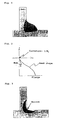
- Japanese Unexamined Patent Publication No. Hei-6-126453 the shape of a bead in a case of fillet welding is calculated in accordance with [Numerical formula 1].
- ? represents density of molten metal
- g represents acceleration of gravity
- s represents surface tension of molten metal
- x, y, a, and R 0 represent, in terms of coordinate axes x and y, an angle a between the tangent line of a bead shape and a curvature R 0 of the y-axis.
- a first aspect of the present invention is a method for calculating the shape of a bead of a welded part in arc welding comprising the steps of:
- a second aspect of the present invention is a method for calculating the shape of a bead of a welded part in arc welding comprising the steps of:
- a third aspect of the present invention is a method for calculating the shape of a bead of a welded part in arc welding comprising the steps of:
- a fourth aspect of the present invention is a method for calculating the shape of a bead of a welded part in arc welding comprising the steps of:
- heat conduction calculation is calculated by a finite difference method or an analytic solution, or by preference from these methods.
- a calculation is carried out by using a finite difference method as a solution of a curved surface equation.
- the calculation end criterion is that the shape of the melting part and/or the displacement shape does not vary or is within an allowable error, or the calculation end criterion is the number of calculations of the shape of the melting part and/or the displacement shape.
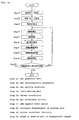
- Fig. 5 shows a flowchart in a case where the method of the present invention is used.
- Step 1 numerical data on a joint shape as an object to be welded is set.
- CAD data is converted to data suitable for calculation according to the present invention, or a numerical formula that expresses a joint shape in advance is used.
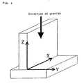
- Fig. 5 shows a schematic view of the set geometric data.
- parameters for determining heat conductivity, specific heat, density, latent heat, a melting point temperature, a transformation point and the like, which are characteristic values of materials, are set based on board thickness, material, gaps between joints, and room temperature.
- the welding current, welding voltage, welding speed, torch target angle, torch lead angle, torch target position, electrode system, electrode tip angle, shielding gas type, distance between the electrode and base metal and the like are set.
- a heat conduction calculation is carried out based on the data set in Step 1 through Step 3, thereby extracting a temperature range equal to or higher than the melting point temperature.
- a method is used such that a finite difference is determined by tailor-developing a nonlinear heat conduction equation or a linear heat conduction equation and a solution is determined by a finite difference method, or a solution is determined by an analytical solution of the heat conduction equation.
- a nonlinear heat conduction equation of [Numerical formula 2] is used. provided that K: heat conductivity, T: temperature, c: specific heat, ?: density, and v: welding speed.
- Step 6 with respect to the melting part of Step 4 which has been coordinate-rotated in Step 5, a difference lattice is set by the X,Y',Z' coordinate system, which is a displacement calculation coordinate system for the melting part.
- a finite difference is determined by tailor-developing [Numerical formula 3] that expresses a curved surface equation, and displacement of a weld bead is calculated with the difference lattice set in Step 6 by a finite difference method.
- ⁇ angle of rotation about the x-axis
- Pa arc pressure
- ⁇ constant number.
- Step 8 the displacement data of the weld bead calculated in Step 7 is rotated by an angle the same as that of coordinate rotation in Step 5 in a direction opposite to that of coordinate rotation in Step 5, whereby the coordinate system is returned to the coordinate system shown in Fig. 6.
- Step 9 the latest shape of the bead displacement determined by calculation and the shape of the bead displacement determined by the preceding calculation are compared and it is judged as to whether the error is within the range of a preset welding shape error. Furthermore, the latest shape of the bead displacement determined by calculation and the shape of the bead displacement determined by the preceding calculation are compared and it is judged as to whether the error is within the range of a preset displacement shape error.
- the process ends and if not, an inference calculation of the melting part of Step 4 is carried out based on the result after displacement calculation, and Step 4 through Step 9 are repeated until convergence is attained.
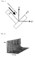
- Fig. 8 shows a bead shape of a welded part calculated by the method of the present invention, wherein it is understood that the portion of a recess which has occurred over a flange and a web is satisfactorily expressed, which has been impossible by the prior method.
- Fig. 9 shows a flowchart in a case where the method of the present invention is used.
- Step 11 numerical data on a joint shape as an object to be welded is set.
- CAD data is converted to data suitable for calculation according to the present invention, or a numerical formula that expresses a joint shape in advance is used.
- the geometric data set in the above-mentioned Fig. 6 is used.
- parameters for determining heat conductivity, specific heat, density, latent heat, a melting point temperature, a transformation point and the like, which are characteristic values of materials, are set based on board thickness, material, gaps between joints, and room temperature.
- the welding current, welding voltage, welding speed, torch target angle, torch lead angle, torch target position, electrode system, electrode tip angle, shielding gas type, distance between the electrode and base metal and the like are set.
- Step 14 coordinates are rotated about an x-axis of Fig. 6, thereby defining a new coordinate system of X,Y',Z' of Fig. 7. In the present embodiment, this coordinate system is rotated by 45°.
- a heat conduction calculation is carried out based on the data set in Step 11 through Step 14, thereby extracting a temperature range equal to or higher than the melting point temperature.
- a method is used such that a finite difference is determined by tailor-developing a nonlinear heat conduction equation or a linear heat conduction equation and a solution is determined by a finite difference method, or a solution is determined by an analytical solution of the heat conduction equation.
- a nonlinear heat conduction equation of the above-mentioned [Numerical formula 2] is used.
- Step 16 with respect to the melting part of Step 15. a difference lattice is set by the X,Y',Z' coordinate system, which is a displacement calculation coordinate system for the melting part.
- a finite difference is determined by tailor-developing the above-mentioned [Numerical formula 3] that expresses a curved surface equation, and displacement of a weld bead is calculated with the difference lattice set in Step 16 by a finite difference method.
- Step 18 the latest shape of the bead displacement determined by calculation and the shape of the bead displacement determined by the preceding calculation are compared and it is judged as to whether the error is within the range of a preset welding shape error. Furthermore, the latest shape of the bead displacement determined by calculation and the shape of the bead displacement determined by the preceding calculation are compared and it is judged as to whether the error is within the range of a preset displacement shape error.
- Step 15 if the welding shape error and bead displacement shape error are within the respective range of errors (convergence) or the number of loops has reached a preset upper limit, the process ends and if not, an inference calculation of the melting part of Step 15 is carried out based on the result after displacement calculation, and Step 15 through Step 18 are repeated until convergence is attained.
- Step 19 the position data of the melting part calculated in Step 15 and displacement data of the weld bead calculated in Step 17 is rotated by an angle the same as that of coordinate rotation in Step 14 in a direction opposite to that of coordinate rotation in Step 14, whereby the coordinate system is returned to the coordinate system shown in Fig. 6.
- Fig. 10 shows a flowchart in a case where the method of the present invention is used.
- CAD data is converted to data suitable for calculation according to the present invention, or a numerical formula that expresses a joint shape in advance is used.
- a schematic diagram of the set geometric data is the same as the above-mentioned Fig. 6.
- parameters for determining heat conductivity, specific heat, density, latent heat, a melting point temperature, a transformation point and the like, which are characteristic values of materials, are set based on board thickness, material, gaps between joints, and room temperature.
- the welding current, welding voltage, welding speed, torch target angle, torch lead angle, torch target position, electrode system, electrode tip angle, shielding gas type, distance between the electrode and base metal and the like are set.
- a heat conduction calculation is carried out based on the data set in Step 21 through Step 23, thereby extracting a temperature range equal to or higher than the melting point temperature.
- a method is used such that a finite difference is determined by tailor-developing a nonlinear heat conduction equation or a linear heat conduction equation and a solution is determined by a finite difference method, or a solution is determined by an analytical solution of the heat conduction equation.
- a nonlinear heat conduction equation of the above-mentioned [Numerical formula 2] is used.
- Step 26 with respect to the melting part of Step 24 which has been coordinate-rotated in Step 25, a difference lattice is set by the X,Y',Z' coordinate system, which is a displacement calculation coordinate system for the melting part.
- the addition of a deposit metal amount of Step 27 can be determined by calculating the amount of deposit metal by generally known relational expressions between the melting rate and welding current/welding wire extension/welding wire diameter.
- a finite difference is determined by tailor-developing the above-mentioned [Numerical formula 3] that expresses a curved surface equation, and displacement of a weld bead is calculated with the difference lattice set in Step 6 by a finite difference method.
- Step 29 the displacement data of the weld bead calculated in Step 27 is rotated by an angle the same as that of coordinate rotation in Step 25 in a direction opposite to that of coordinate rotation in Step 25, whereby the coordinate system is returned to the coordinate system shown in Fig. 6.
- Step 30 the latest shape of the melting part determined by calculation and the shape of the melting part determined by the preceding calculation are compared and it is judged as to whether the error is within the range of a preset welding shape error. Furthermore, the latest shape of the bead displacement determined by calculation and the shape of the bead displacement determined by the preceding calculation are compared and it is judged as to whether the error is within the range of a preset displacement shape error.
- Step 24 if the welding shape error and bead displacement shape error are within the respective range of errors (convergence) or the number of loops has reached a preset upper limit, the process ends and if not, an inference calculation of the melting part of Step 24 is carried out based on the result after displacement calculation, and Step 24 through Step 30 are repeated until convergence is attained.
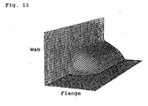
- Fig. 11 shows a bead shape of a welded part calculated by the method of the present invention, which indicates preferable results free of weld defects such as undercuts.
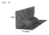
- Fig. 12 showing an example by the prior method, weld failures of undercuts have occurred on the flange side and on the web side, therefore it is understood that the portions to undercuts which have occurred on both flange and web sides are satisfactorily expressed, which has been impossible by the prior method.
- Fig. 13 shows a flowchart in a case where the method of the present invention is used.
- Step 41 numerical data on a joint shape as an object to be welded is set.
- CAD data is converted to data suitable for calculation according to the present invention, or a numerical formula that expresses a joint shape in advance is used.
- a schematic diagram of the set geometric data is the same as that shown in the above-mentioned Fig. 6.
- parameters for determining heat conductivity, specific heat, density, latent heat, a melting point temperature, a transformation point and the like, which are characteristic values of materials, are set based on board thickness, material, gaps between joints, and room temperature.
- the welding current, welding voltage, welding speed, torch target angle, torch lead angle, torch target position, electrode system, electrode tip angle, shielding gas type, distance between the electrode and base metal and the like are set.
- a heat conduction calculation is carried out based on the data set in Step 41 through Step 44, thereby extracting a temperature range equal to or higher than the melting point temperature.
- a method is used such that a finite difference is determined by tailor-developing a nonlinear heat conduction equation or a linear heat conduction equation and a solution is determined by a finite difference method, or a solution is determined by an analytical solution of the heat conduction equation.
- a nonlinear heat conduction equation of the above-mentioned [Numerical formula 2] is used.
- Step 44 coordinates are rotated about an x-axis of Fig. 6, thereby defining a new coordinate system of X,Y',Z' of Fig. 7. In the present embodiment, this coordinate system is rotated by 45°.
- Step 46 with respect to the melting part, which has been coordinate-rotated in Step 44 and calculated in Step 45, a difference lattice is set by the X,Y',Z' coordinate system, which is a displacement calculation coordinate system for the melting part.
- the addition of a deposit metal amount of Step 47 can be determined by calculating the amount of deposit metal by generally known relational expressions between the melting rate and welding current/welding wire extension/welding wire diameter.
- a finite difference is determined by tailor-developing the above-mentioned [Numerical formula 3] that expresses a curved surface equation, and displacement of a weld bead is calculated with the difference lattice set in Step 46 by a finite difference method.
- Step 50 In reverse coordinate rotation of Step 50, the position data of the melting part calculated in Step 45 and displacement data of the weld bead calculated in Step 48 is rotated by an angle the same as that of coordinate rotation in Step 44 in a direction opposite to that of coordinate rotation in Step 44, whereby the coordinate system is returned to the coordinate system shown in Fig. 6.
- Step 49 the latest shape of the melting part determined by calculation and the shape of the melting part determined by the preceding calculation are compared and it is judged as to whether the error is within the range of a preset welding shape error. Furthermore, the latest shape of the bead displacement determined by calculation and the shape of the bead displacement determined by the preceding calculation are compared and it is judged as to whether the error is within the range of a preset displacement shape error.
- Step 45 if the welding shape error and bead displacement shape error are within the respective range of errors (convergence) or the number of loops has reached a preset upper limit, the process ends and if not, an inference calculation of the melting part of Step 45 is carried out based on the result after displacement calculation, and Step 45 through Step 49 are repeated until convergence is attained.
- the bead shape of a welded part calculated by the method of the present invention is the same as Fig. 11, which indicates preferable results free of weld defects such as undercuts.
- Fig. 12 weld failures of undercuts have occurred on the flange side and on the web side, therefore, it is understood that the portions of undercuts which have occurred on both flange and web sides are satisfactorily expressed, which had been impossible by the prior method.
- the present invention is advantageous as a method for accurately calculating numerical values of a bead shape for arc welding.
Landscapes
- Engineering & Computer Science (AREA)
- Mechanical Engineering (AREA)
- Physics & Mathematics (AREA)
- Plasma & Fusion (AREA)
- Theoretical Computer Science (AREA)
- Quality & Reliability (AREA)
- Length Measuring Devices With Unspecified Measuring Means (AREA)
- Butt Welding And Welding Of Specific Article (AREA)
- Investigating Or Analyzing Materials Using Thermal Means (AREA)
- Arc Welding In General (AREA)
Abstract
Description


Claims (10)
- A method for calculating the shape of a bead of a welded part in arc welding comprising the steps of:setting geometric data on the object to be welded, characteristic parameters of the object and welding environment, and welding conditions,inferring, under the welding conditions, the melting part of the object by a heat conduction calculation,rotating the coordinates about an axis parallel to the direction of the welding and/or about an axis perpendicular to the welding direction for the calculated melting part,setting a difference lattice for the coordinate-rotated melting part,calculating displacement of the melting part, for which the difference lattice is set, by a curved surface equation,rotating the welding shape determined by the calculated displacement by the same angle of rotation as that of the coordinate rotation in the opposite direction to the rotation direction, andrepeatedly calculating the inference of the melting part by the heat conduction calculation of the displacement shape, the coordinate rotation, the setting of the difference lattice, and the calculation of the displacement of the melting part until a calculation end criterion is met.
- A method for calculating the shape of a bead of a welded part in arc welding comprising the steps of:setting geometric data on the object to be welded, characteristic parameters of the object and welding environment. and welding conditions,rotating the coordinates about an axis parallel to the direction of the welding of the object and/or about an axis perpendicular to the weld line direction,inferring, based on preset welding conditions, the melting part of the object by a heat conduction calculation,setting a difference lattice for the melting part,calculating displacement of the melting part, for which the difference lattice is set, by a curved surface equation,repeatedly calculating the inference of the melting part by the heat conduction calculation of the displacement shape, the setting of the difference lattice, and the calculation of the displacement of the melting part until a calculation end criterion is met, androtating the shape of the invariable melting part and displacement shape by the same angle of rotation as that of the coordinate rotation in the opposite direction to the rotation direction.
- A method for calculating the shape of a bead of a welded part in arc welding comprising the steps of:setting geometric data on the object to be welded, characteristic parameters of the object and welding environment, and welding conditions,inferring, under the welding conditions, the melting part of the object by a heat conduction calculation,rotating the coordinates about an axis parallel to the direction of the welding and/or about an axis perpendicular to the welding direction for the calculated melting part,setting a difference lattice for the coordinate-rotated melting part,adding deposit metal by an amount determined based on the welding conditions to the melting part for which the difference lattice is set,calculating the displacement of the deposit metal by a curved surface equation,rotating the welding shape determined by the calculated displacement by the same angle of rotation as that of the coordinate rotation in the opposite direction to the rotation direction, andrepeatedly calculating the inference of the melting part by the heat conduction calculation of the displacement shape, the coordinate rotation, the setting of the difference lattice, the addition of the deposit metal amount, and the calculation of the displacement of the deposit metal until a calculation end criterion is met.
- A method for calculating the shape of a bead of a welded part in arc welding comprising the steps of:setting geometric data on the object to be welded, characteristic parameters of the object and welding environment, and welding conditions,rotating the coordinates about an axis parallel to the direction of the welding of the object and/or about an axis perpendicular to the weld line direction,inferring, based on preset welding conditions, the melting part of the object by a heat conduction calculation,setting a difference lattice for the melting part, adding deposit metal by an amount determined based on the welding conditions,calculating the displacement of the deposit metal, for which the difference lattice is set, by a curved surface equation,repeatedly calculating the inference of the melting part by the heat conduction calculation of the displacement shape, the setting of the difference lattice, the addition of the deposit metal amount and the calculation of the displacement of the melting part until a calculation end criterion is met, androtating the shape of the invariable melting part and displacement shape by the same angle of rotation as that of the coordinate rotation in the opposite direction to the rotation direction.
- A method for calculating the shape of a bead of a welded part as set forth in any of Claim 1 through Claim 4, wherein
a heat conduction calculation is calculated by a finite difference method. - A method for calculating the shape of a bead of a welded part as set forth in any of Claim 1 through Claim 4, wherein
a heat conduction calculation is calculated by an analytic solution of a heat conduction equation. - A method for calculating the shape of a bead of a welded part as set forth in any of Claim 1 through Claim 4, wherein
a heat conduction calculation is calculated by freely selecting an analytic solution of a heat conduction equation or a finite difference method. - A method for calculating the shape of a bead of a welded part as set forth in any of Claim 1 through Claim 4, wherein
a calculation is carried out by using a finite difference method as a solution of a curved surface equation. - A method for calculating the shape of a bead of a welded part as set forth in any of Claim 1 through Claim 4, wherein
the calculation end criterion is that the shape of the melting part and/or the displacement shape does not vary or is within an allowable error range. - A method for calculating the shape of a bead of a welded part as set forth in any of Claim 1 through Claim 4, wherein
the calculation end criterion is the number of calculations of the shape of the melting part and/or the displacement shape.
Applications Claiming Priority (3)
| Application Number | Priority Date | Filing Date | Title |
|---|---|---|---|
| JP2000009491 | 2000-01-18 | ||
| JP2000009491A JP2001205437A (en) | 2000-01-18 | 2000-01-18 | Calculation method of bead shape of weld |
| PCT/JP2001/000281 WO2001053029A1 (en) | 2000-01-18 | 2001-01-17 | Method for calculating shape of bead of welded part |
Publications (2)
| Publication Number | Publication Date |
|---|---|
| EP1258311A1 true EP1258311A1 (en) | 2002-11-20 |
| EP1258311A4 EP1258311A4 (en) | 2007-08-01 |
Family
ID=18537636
Family Applications (1)
| Application Number | Title | Priority Date | Filing Date |
|---|---|---|---|
| EP01901407A Withdrawn EP1258311A4 (en) | 2000-01-18 | 2001-01-17 | METHOD FOR CALCULATING THE FORM OF A WELDING STICK |
Country Status (6)
| Country | Link |
|---|---|
| US (1) | US6831250B2 (en) |
| EP (1) | EP1258311A4 (en) |
| JP (1) | JP2001205437A (en) |
| KR (1) | KR100708012B1 (en) |
| CN (1) | CN1395517A (en) |
| WO (1) | WO2001053029A1 (en) |
Families Citing this family (13)
| Publication number | Priority date | Publication date | Assignee | Title |
|---|---|---|---|---|
| US6822195B2 (en) * | 2003-04-02 | 2004-11-23 | General Motors Corporation | Automated weld location system for vehicles |
| US8253062B2 (en) * | 2005-06-10 | 2012-08-28 | Chrysler Group Llc | System and methodology for zero-gap welding |
| EA013206B1 (en) * | 2005-12-22 | 2010-04-30 | Эксонмобил Апстрим Рисерч Компани | Methods for enhancing strain performance to a capacity preventing failure of a welded joint and determining geometry of a weld joint, a system of tubular weld joints and apparatus to determine the geometry of a weld joint |
| JP5426076B2 (en) * | 2007-02-19 | 2014-02-26 | 株式会社ダイヘン | Arc welding bead shape simulation device |
| US9040865B2 (en) | 2007-02-27 | 2015-05-26 | Exxonmobil Upstream Research Company | Corrosion resistant alloy weldments in carbon steel structures and pipelines to accommodate high axial plastic strains |
| US8410400B2 (en) * | 2008-12-12 | 2013-04-02 | Material Sciences Corporation | Welded metal laminate structure and method for welding a metal laminate structure |
| JP5178624B2 (en) * | 2009-05-11 | 2013-04-10 | 株式会社日立製作所 | Analysis model generator |
| CN102620084A (en) * | 2012-03-14 | 2012-08-01 | 昆山振昆纳米科技有限公司 | Calipers flange welded type bellows |
| CN102620082A (en) * | 2012-03-14 | 2012-08-01 | 昆山振昆纳米科技有限公司 | Welded connection structure of bellows and joints |
| EP2849151A1 (en) * | 2013-09-13 | 2015-03-18 | Xovis AG | Method for analysis of free queues |
| JP2017170472A (en) * | 2016-03-23 | 2017-09-28 | 株式会社神戸製鋼所 | Welding condition setting support device in multi-layer welding |
| JP6738789B2 (en) * | 2017-11-29 | 2020-08-12 | 株式会社神戸製鋼所 | Laminated object design method, manufacturing method, manufacturing apparatus, and program |
| EP3892517A4 (en) * | 2018-12-05 | 2022-08-31 | Nippon Steel Corporation | STRESS EVALUATION METHOD FOR RAIL VEHICLE BOGIE FRAME RAW WELDING PART |
Family Cites Families (13)
| Publication number | Priority date | Publication date | Assignee | Title |
|---|---|---|---|---|
| JPS638687A (en) | 1986-06-25 | 1988-01-14 | インスチテユ−ト プロブレム モデリロヴアニア ヴエ エネルゲテイケ アカデミイ ナウク ウクラインスコイ エスエスア−ル | Welder training apparatus |
| JPH0675787B2 (en) | 1986-09-30 | 1994-09-28 | 株式会社安川電機 | Multi-layer welding method |
| US4724302A (en) * | 1987-03-30 | 1988-02-09 | General Electric Company | Bead process control with profiler |
| US4920249A (en) * | 1989-05-08 | 1990-04-24 | General Electric Company | Weld bead wetting angle detection and control |
| JPH04111975A (en) * | 1990-08-31 | 1992-04-13 | Nippon Steel Corp | Multiple electrode one-side submerged arc welding method |
| JPH06126453A (en) | 1992-10-16 | 1994-05-10 | Mitsubishi Heavy Ind Ltd | Automatic welding condition selecting method |
| US5386142A (en) * | 1993-05-07 | 1995-01-31 | Kulite Semiconductor Products, Inc. | Semiconductor structures having environmentally isolated elements and method for making the same |
| JP3233772B2 (en) | 1993-12-10 | 2001-11-26 | 三菱重工業株式会社 | Welding work simulator device |
| DE19700734B4 (en) * | 1997-01-11 | 2006-06-01 | Robert Bosch Gmbh | Method for producing sensors and non-isolated wafer stacks |
| US6081171A (en) * | 1998-04-08 | 2000-06-27 | Nokia Mobile Phones Limited | Monolithic filters utilizing thin film bulk acoustic wave devices and minimum passive components for controlling the shape and width of a passband response |
| US6062461A (en) * | 1998-06-03 | 2000-05-16 | Delphi Technologies, Inc. | Process for bonding micromachined wafers using solder |
| US6024273A (en) * | 1998-12-04 | 2000-02-15 | Caterpillar Inc. | Method and system for determining weld bead quality |
| US6514789B2 (en) * | 1999-10-26 | 2003-02-04 | Motorola, Inc. | Component and method for manufacture |
-
2000
- 2000-01-18 JP JP2000009491A patent/JP2001205437A/en not_active Abandoned
-
2001
- 2001-01-17 WO PCT/JP2001/000281 patent/WO2001053029A1/en not_active Ceased
- 2001-01-17 EP EP01901407A patent/EP1258311A4/en not_active Withdrawn
- 2001-01-17 US US10/169,754 patent/US6831250B2/en not_active Expired - Fee Related
- 2001-01-17 KR KR1020027009207A patent/KR100708012B1/en not_active Expired - Fee Related
- 2001-01-17 CN CN01803802A patent/CN1395517A/en active Pending
Also Published As
| Publication number | Publication date |
|---|---|
| KR20020067932A (en) | 2002-08-24 |
| WO2001053029A1 (en) | 2001-07-26 |
| EP1258311A4 (en) | 2007-08-01 |
| US6831250B2 (en) | 2004-12-14 |
| JP2001205437A (en) | 2001-07-31 |
| KR100708012B1 (en) | 2007-04-16 |
| US20030010764A1 (en) | 2003-01-16 |
| CN1395517A (en) | 2003-02-05 |
Similar Documents
| Publication | Publication Date | Title |
|---|---|---|
| CN110153534B (en) | A multi-layer multi-pass robot welding path planning method and system adapting to welding deformation | |
| CN109475958B (en) | Method for establishing welding parameters of a welding process | |
| US6831250B2 (en) | Method for calculating shape of bead of welded part | |
| EP4137259B1 (en) | Laminate molding method | |
| CN113275708B (en) | Enhanced automatic welding system and method for first and second workpieces | |
| CN106457441B (en) | Welding condition guiding device | |
| CN111496428B (en) | Multilayer multi-pass welding bead planning method based on straight welding seam contour recognition and welding workstation | |
| CN110052692B (en) | V-groove robot welding path planning method and system | |
| EP3974091A1 (en) | Additive manufacturing method, additive manufacturing device, and controller | |
| Baek et al. | Development of an automatic orbital welding system with robust weaving width control and a seam-tracking function for narrow grooves | |
| CN117644327B (en) | Automatic welding system | |
| Zhang et al. | A segmentation planning method based on the change rate of cross-sectional area of single V-groove for robotic multi-pass welding in intersecting pipe-pipe joint | |
| CN110076420B (en) | Dynamic welding path planning method and system for thick plate robot considering angular deformation | |
| CN114951906A (en) | Welding system and method for operating a welding system | |
| JP2018083229A (en) | Deviation amount detection method in arc tracking welding | |
| CN116021119B (en) | Petrochemical process pipeline robot welding assembly misalignment detection system and method | |
| Kuss et al. | Automated planning of robotic MAG welding based on adaptive gap model | |
| CN111014878A (en) | Tree-shaped special swing welding method | |
| JP7473508B2 (en) | Method for evaluating molded object and method for manufacturing molded object | |
| JP7856445B2 (en) | Defect monitoring device, defect monitoring method, welding support system, and welding system | |
| CN114932295B (en) | Welding method | |
| WO2018088372A1 (en) | Arc welding display device and display method | |
| CN106181159A (en) | Groove weld robot downhand welding welding method | |
| Penttilä et al. | Weld quality verification by using laser triangulation measurement | |
| US20250033133A1 (en) | Learning device, defect determination apparatus, learning method, defect determination method, welding control device, and welding device |
Legal Events
| Date | Code | Title | Description |
|---|---|---|---|
| PUAI | Public reference made under article 153(3) epc to a published international application that has entered the european phase |
Free format text: ORIGINAL CODE: 0009012 |
|
| 17P | Request for examination filed |
Effective date: 20020628 |
|
| AK | Designated contracting states |
Kind code of ref document: A1 Designated state(s): AT BE CH CY DE DK ES FI FR GB GR IE IT LI LU MC NL PT SE TR |
|
| RBV | Designated contracting states (corrected) |
Designated state(s): AT BE CH CY DE FR GB LI SE |
|
| A4 | Supplementary search report drawn up and despatched |
Effective date: 20070702 |
|
| RIC1 | Information provided on ipc code assigned before grant |
Ipc: G06F 19/00 20060101ALI20070626BHEP Ipc: B23K 9/095 20060101AFI20010731BHEP |
|
| 17Q | First examination report despatched |
Effective date: 20070921 |
|
| RTI1 | Title (correction) |
Free format text: METHODS OF CALCULATING SHAPE OF BEAD OF WELDED PART |
|
| GRAP | Despatch of communication of intention to grant a patent |
Free format text: ORIGINAL CODE: EPIDOSNIGR1 |
|
| RBV | Designated contracting states (corrected) |
Designated state(s): DE FR GB SE |
|
| STAA | Information on the status of an ep patent application or granted ep patent |
Free format text: STATUS: THE APPLICATION IS DEEMED TO BE WITHDRAWN |
|
| 18D | Application deemed to be withdrawn |
Effective date: 20090530 |