Technical Field
The present invention relates to space heaters such as
kerosene fan heaters and the like.
Background Art
Kerosene fan heaters have been widely used in typical
homes as a space heater during the winter. Fig.119 is a partly
abbreviated front sectional view schematically showing an
example of a conventional kerosene fan heater. Fig.120 is
a sectional side view of the same type. Fig.121 is a sectional
view showing a filler cap and a socket of a fuel supply tank.
As shown in Fig.119, a kerosene fan heater body 101
incorporates a fuel supply tank 102 for being previously filled
with a liquid fuel 104 such as kerosene as reserve fuel, at
one side therein, so that an ample amount of liquid fuel 104
will be supplied to a fuel tank 103 connected under the fuel
supply tank 102.
Liquid fuel 104 held in the fuel tank 103 is led by a
fuel pressure-feed electromagnetic pump 105 to a vaporizer
107 by way of an oil feed pipe 106. The thus fed liquid fuel
104 is vaporized by a vaporizer heater (not shown) provided
for vaporizer 107. Designated at 109 is a combustion chamber,
which supports and fixes a burner 108 at the bottom of thereof.
The fuel vaporized through the vaporizer 107 is intensely
jetted from a nozzle and led together with combustion air
into the burner 108 and burns at a flame port 108a, whereby
air inside combustion chamber 109 is heated. As indicated
by the arrows in Fig.120, air is suctioned through a filter
112 from the room by a blower fan 111 attached to a fan motor
110 of a single-phase induction motor or the like arranged
at the rear side of main body 101 and blown out together with
the heated air and combustion gas inside combustion chamber
109, as warm air through an air outlet 113 to the room.
A flame sensor 114, arranged slightly above flame port
108a, is to detect flame current derived from the burning
flame and when it detects a flame current equal to or greater
than the preset value, it activates the fan motor 110 so that
blower fan 111 starts rotating, whereby air sucked from the
room is blown out as warm air through air outlet 113 to the
room. At the same time, the room temperature is sensed by
a room temperature thermistor 115, and based on the temperature
difference between the room temperature and a set temperature,
a controller (not shown) controls the drive of the fuel
pressure-feed electromagnetic pump 105 (see Fig. 119), whereby
the amount of liquid fuel 104 supplied to vaporizer 107 is
regulated to control the power of the burning flame at burner
108.
For example, when a kerosene fan heater starts its
operation when the room temperature is low, a large amount
of liquid fuel 104 is supplied to vaporizer 107 so as to quickly
raise the room temperature to the set level and thereafter
the supplied amount of liquid fuel 104 is regulated so as
to maintain the temperature at about the preset level.
As shown in Fig.121, fuel supply tank 102 is refueled
by taking out fuel supply tank 102 from main body 101 and
turning it upside down, removing a filler cap 116 having a
valve element of fuel supply tank 102, charging fuel through
a mouth 117, confirming the correct supply of fuel into fuel
supply tank 102, then fixing filler cap 116 to the threaded
portion of mouth 117, turning the tank upside down so that
filler cap 116 is downside and inserting it into main body
101, and placing it on fuel tank 103 so that filler cap 116
fits into a socket 118 attached to the top face of fuel tank
103.
The conventional kerosene fan heaters need tedious
handling: that is, it is necessary when refueling to take
out the fuel supply tank from the main body and invert the
fuel supply tank to turn its filler cap side up. Further,
after refueling, it is necessary to fasten the filler cap
and turn the tank upside down once again in order to fit it
into the main body.
Further, since the engagement of the filler cap with
the mouth is made by screw fastening, there have been problems
such that the filler cap falls off or fuel flows out when
the fuel supply tank is turned upside down if fastening of
the filler cap is insufficient. In particular, in an aging
society, there has been a demand for improvement because the
grip strength and also force for tightening the screw lowers
as users become older.
When fuel is supplied into the fuel tank, fuel is delivered
into the fuel tank by air replacement while the oil level
rises up to the valve element of the filler cap and is kept
at the fixed height. This means that the valve element of
the filler cap is constantly wetted with fuel. Accordingly,
there have been problems such that when the filler cap needs
to be removed to refuel the fuel supply tank, the hands are
stained with fuel and hence slip when the screw is fastened
as well as the hands being left polluted and smelling of fuel.
Further, to clean impurities in the vaporizer by baking,
requires the tedious work of taking out the fuel supply tank
from the main body and removing the remaining oil in the bottom
of the fuel tank under the fuel supply tank using a pump etc.,
resulting dissatisfaction.
In view of the above problems, it is therefore an object
of the present invention to provide a liquid fuel burning
apparatus which allows refueling the fuel supply tank without
turning the tank upside down and without any staining of the
hands with fuel and which permits cleaning of the vaporizer
by baking without the necessity of clearing fuel.
Disclosure of Invention
The present invention resides in a liquid fuel burning
apparatus which comprises: a fuel supply tank detachably
mounted into a main body of the liquid fuel burning apparatus;
a burner unit having a vaporizer for vaporizing fuel by heating
and a burner for burning the vaporized fuel; an oil feed pump
for sending fuel from the fuel supply tank to the vaporizer;
and a first joining portion for creating connection of oil
feed passage from the fuel supply tank to the burner unit
when the fuel supply tank is mounted to the main body, and
is characterized in that the first joining portion comprises
an oil feed joint provided on the fuel supply tank side and
an oil feed joint socket provided on the main body side for
detachably receiving the oil feed joint. This arrangement
makes it possible to directly feed fuel from the fuel supply
tank to the burner unit without providing any fuel tank for
temporarily holding fuel which is conventionally disposed
under the fuel supply tank. Thereby, the oil feed passage
can be constituted of a reduced number of parts while the
fuel supply tank can be made to be easy to handle without
the necessity of turning the fuel supply tank upside down
when the tank is refueled.
When the apparatus further includes a second joining
portion for creating connection of return oil passage from
the burner unit to the fuel supply tank and is configured
so that the second joining portion comprises a return oil
joint provided on the fuel supply tank side and a return oil
joint socket provided on the main body side for detachably
receiving the return oil joint, fuel can be returned to the
fuel supply tank.
When the oil feed joint, or the oil feed joint, oil feed
joint socket and return oil joint each incorporate a valve
mechanism for opening and closing oil feed passage, it is
possible to secure reliable oil feed to the burner unit.
Further, provision of a shutoff valve for shutting off
fuel supply from the fuel supply tank to the burner unit,
within the oil feed passage makes it possible to positively
shut off fuel supply in accordance with shutoff valve control.
The shutoff valve comprises an air valve which leads air into
the oil feed passage so as to shut off fuel supply from the
fuel supply tank to the burner unit.
Further, the path in the oil feed joint connected to
the suction path inside the fuel supply tank is arranged above
the liquid level of fuel in the fuel supply tank. This
arrangement makes it possible to avoid the fuel spilling out
even when the fuel supply tank is filled up with fuel.
The fuel path connecting the fuel supply tank and the
oil feed pump is formed by an inverted U-shaped upturned path
and the top end of the upturned path is located above the
liquid level of fuel in the fuel supply tank. This arrangement
makes it possible to avoid the fuel spilling out even when
the fuel supply tank is filled up with fuel.
The upturned path is formed on the main body side while
the shutoff valve is arranged at the top end of the upturned
path. Therefore, this arrangement makes it possible to avoid
the fuel spilling out even when the fuel supply tank is filled
up with fuel.
The exit of the fuel path of the return oil joint on
the fuel supply tank side is arranged above the liquid level
of fuel in the fuel supply tank, or the exit of the fuel path
of the return oil joint is upturned so that it is positioned
above the liquid level of fuel in the fuel supply tank. Either
of the above arrangement makes it possible to avoid the fuel
spilling out even when the fuel supply tank is filled up with
fuel.
The air intake port of the air valve is arranged above
the liquid level of fuel in the fuel supply tank. This
arrangement makes it possible to avoid the fuel spilling out
even when the fuel supply tank is filled up with fuel.
Further, provision of an air hole on the top face of
the fuel supply tank makes it possible to avoid increase the
pressure in the fuel supply tank due to a temperature rise.
Provision of a shutoff mechanism for closing the air hole
when the tank falls down makes it possible to prevent fuel
leakage from the air hole when the tank falls down.
Setting the inside diameter of the return oil passage
so as to be greater than the inner diameter of the oil feed
passage, makes it possible to quickly return the fuel inside
the pipe to the fuel supply tank.
When insertion of the fuel supply tank into the main
body is permitted only in such a way that the tank is oriented
to one determined direction, this makes it possible to prevent
other parts from being damaged when the fuel supply tank is
inserted.
The oil feed joint and the return oil joint on the fuel
supply tank side are integrated into a fuel supply tank side
joint unit while the oil feed joint socket and the return
oil joint socket on the main body side are integrated into
a main body side joint socket unit. This arrangement makes
the first and second joining means compact and enables them
to be assembled by fewer steps.
The position and placement of this joint unit on the
fuel supply tank side is not particularly limited as long
as it is arranged in the upper part of the fuel supply tank.
However, in the case where the joint unit is adapted to be
connected to the joint socket unit on the burner unit side
when the fuel supply tank is inserted from the top of the
main body into the tank holding compartment, no functional
parts can be laid out under the oil feed joint unit.
Therefore, the oil feed joint unit is, in effect,
projected from the exterior of the fuel supply tank, so that
the fuel supply tank has a large projection area. Generally,
the fuel supply tank is formed by joining a U-shaped tank
part, when viewed from top and a flat sheet tank part.
Therefore, in order to reduce the projection area of the fuel
supply tank, it is preferred that part of the inverted U-shaped
tank part, on its side opposite to the joint-forming face
of the fuel supply tank, is depressed inwards so as to allow
the placement of the joint unit in the thus formed depressed
portion.
It is necessary to connect the pipe for the suction path
from the fuel supply tank and the return pipe for returning
fuel into the tank. Means for positioning and connecting these
pipes entering the fuel supply tank may be provided in the
joint unit, so that the pipes can be positioned easily without
the necessity of a special jig.
In this case, the pipes may be fixed to the fuel supply
tank side joint unit by the fastening means of the pipes in
the fuel supply tank, so that connecting work of the pipes
can be simply performed needing a smaller work space.
The main body side joint socket unit has a shutoff valve
for shutting off fuel supply from the fuel supply tank to
the burner unit and a protective cover for protecting the
shutoff valve while the fuel supply tank side joint unit has
a cushioning cover for protection against impacts so that,
when the fuel supply tank is inserted into the main body,
the two covers serve as tank insertion guides. Thus, the
covers can provide both the protecting function and the
function of insert guidance when fuel supply tank is inserted.
When, in order to detect water in the fuel supply tank,
the apparatus includes a water detecting portion having a
first electrode in contact with a water receptacle provided
at the bottom of the fuel supply tank and a second electrode
in contact with the fuel supply tank, and at least one of
the electrodes is fixed at a point on the detector board and
supported in a cantilevered manner on a fulcrum other the
fixed point, it is possible to disperse the stresses acting
on the electrodes.
It is possible to cool the return oil from the vaporizer,
by providing a fuel container for ICHIJITEKINI holding fuel
or a cooling portion for cooling fuel, within the return oil
passage from the burner unit to the second joining portion.
Further, to mention the shape of the fuel supply tank,
the first joining portion and/or the second joining portion
on the fuel supply tank side to be used when the fuel supply
tank is mounted into the main body is adapted to be positioned
within the ridge-based contour in the top view of the fuel
supply tank, it is possible to prevent the joining portions
from being damaged if, for example, the tank falls down during
its carriage. In the case where these joining portions are
formed with an impact protecting means, it is preferred that
the structure including the impact protecting means is laid
out within the ridge-based contour in the top view of the
fuel supply tank.
Here, the arrangement of the joining portions and the
like within the ridge-based contour in the top view of the
fuel supply tank means, for example, that an approximately
triangular or rectangular space is formed within the
ridge-based contour in the top view of the fuel supply tank,
by setting back the outer shape of the fuel supply tank from
the ridgeline formed by the intersection of two adjoining
sides, toward the tank center, so that the joining portions
and the like are arranged within this space. Alternatively,
this means that a depressed portion is formed within the
ridge-based contour in the top view of the fuel supply tank,
by setting back the outer shape of the fuel supply tank from
one side face thereof toward the tank center, so that joining
portions and the like are arranged within this depressed
portion.
The above joining portions and the like also include
air valves and other parts which are provided for the fuel
supply tank, and all these parts are preferably configured
so as to be arranged within the ridge-based contour in the
top view of the tank.
Provision of a fixture for fixing the suction passage
of fuel toward the oil feed pump inside the fuel supply tank,
makes it possible to prevent the suction passage from
interfering with the inner wall of the oil feed pump during
carriage and hence avoid damage to both.
The arrangement of the first joining portion and/or the
second joining portion above the liquid surface of the fuel
in the fuel supply tank will prevent the fuel in the fuel
supply tank from spilling out.
Provision of a suction pipe for suctioning the fuel to
be sent to the oil feed pump and positioning of the suction
port of the suction pipe for suctioning fuel near the bottom
of the fuel supply tank make efficient suction of fuel possible.
Provision of guide members, which can come into contact
with and separate from each other, on the fuel supply tank
side and on the burner unit side, in the first joining portion
and the second joining portion, makes the connection of the
tank to the main body smooth.
Specifically, according to the present invention, while
no fuel tank for temporarily holding fuel is arranged under
the fuel supply tank, fuel is directly supplied from the fuel
supply tank to the burner so that the oil feed passage can
be constituted by fewer components and the fuel supply tank
can be handled easily. Further, since the tank has the joining
means for joining itself to the oil feed passage reaching
the burner unit, there is no necessity to turn the fuel supply
tank upside down when the tank is refueled.
Concerning the burning system in this case, any of burning
systems defined in JIS S3030, including pot type, pressure
spraying type, rotary atomizing type, jet spraying type and
vaporizing type can be used. The pot type indicates a means
that evaporates fuel using a vaporizing pot, wherein the
vaporizer for evaporating fuel by heating and the burner for
burning the vaporized fuel are formed integrally. The
pressure spraying type indicates a means that pressurizes
fuel into a spray to burn it by evaporation, wherein the
vaporizer and the burner are formed integrally. The rotary
atomizing type indicates a means that atomizes fuel by
centrifugal force to burn it by evaporation. The jet spraying
type indicates a means that atomizes fuel by air jet to burn
it by evaporation, wherein the vaporizer and burner are formed
integrally. The vaporizing type indicates a means that
evaporates fuel in a vaporizing compartment or vaporizer,
wherein the vaporizer and burner are formed separately.
Among these, the pot type, pressure spraying type, rotary
atomizing type and jet spraying type burning systems, which
all have the vaporizer and burner integrated, are preferably
used. That is, the liquid fuel burning apparatus includes
a fuel supply tank detachably mounted into the apparatus body,
a burner unit integrally having a vaporizer for vaporizing
fuel by heating and a burner for burning the vaporized fuel,
and an oil feed pump for sending fuel from the fuel supply
tank to the vaporizer. The fuel in the fuel supply tank is
adapted to be directly fed to the burner unit, instead of
providing a fuel tank for temporarily holding the fuel under
the fuel supply tank.
Since the liquid fuel burning apparatus of the above
direct oil feed types do not temporarily hold fuel in the
fuel tank, which has been used conventionally, it is preferred
that a shutoff valve for shutting off fuel supply is provided
in the oil feed passage from the fuel supply tank to the burner
unit so as to positively shut off fuel supply to the burner
unit.
Since the burning system having a vaporizer and burner
integrated does not need to return fuel from the vaporizer,
provision of a joining means for connection with the fuel
supply tank within the oil feed passage reaching to the burner
works well enough. This joining means can be represented by
a configuration made up of an oil feed joint on the fuel supply
tank side and an oil feed joint socket on the burner unit
side. Further, a valve mechanism which is adapted to open
its valve when the fuel supply tank is mounted to the main
body and close when the fuel supply tank is removed from the
main body may be provided for the oil feed joint. This
arrangement makes it possible to eliminate the risk of fuel
leaking from the fuel supply tank when the tank is removed
and also reliably open the oil feed passage when the tank
is mounted.
This shutoff valve may be arranged in the oil feed passage,
either at a position halfway along the path from the fuel
supply tank to the oil feed pump, or at a position halfway
along the path from the oil feed pump to the burner unit.
Further, the shutoff valve may have any configuration as long
as it provides the function of shutting off the oil feed passage.
For example, an electromagnetic valve or an air valve may
be used. Use of an electromagnetic valve integrated with an
oil feed pump made of an electromagnetic pump or the like,
also makes it possible to achieve space-saving and
simplification of the forming step when the oil feed passage
is joined.
The air valve is provided to take air into the oil feed
passage so as to shut off fuel supply, and can be disposed
at an appropriate position in the oil feed passage. However,
if the air valve is combined with the oil feed joint socket
of the joining means, it is possible to simplify the pipe
joining step, compared to the case where the valve is laid
out at other positions. Further, the air valve is preferably
disposed at a position higher than the maximum liquid level
of fuel in the tank, in order to prevent fuel from leaking
through the air valve when the fuel supply tank is full.
The oil feed pump may be disposed at an appropriate
position in the oil feed passage, for example, at a position
closer to the burner unit side than the joint means is, or
at a position closer to the fuel supply tank side than the
joint means is.
The suctioning path for suctioning fuel from the fuel
supply tank to the oil feed pump needs to be long enough to
almost reach the bottom of the fuel supply tank, a fixing
means may be provided inside the fuel supply tank so that
the path will not move.
Further, since the fuel supply tank is configured so
that fuel is charged without the necessity of turning the
tank upside down, the filler port through which fuel is charged
as well as a filler cap for closing the filler port, is
preferably arranged at the top of the fuel supply tank. It
is more preferable that a valve mechanism for releasing the
pressure inside the tank is provided for the filler cap, so
that no fuel will spill out due to increase in pressure inside
the tank, which is caused by difference in temperature between
the interior and exterior of the tank.
Specifically, the aspect of the present invention resides
in a liquid fuel burning apparatus comprising: a fuel supply
tank detachably mounted into the main body; a vaporizer for
vaporizing fuel by heating; an electromagnetic pump for
sending fuel from the fuel supply tank; and a burner for burning
the vaporized fuel, without having any receptacle for
temporarily holding fuel under the fuel supply tank.
Another aspect resides in a liquid fuel burning apparatus
comprising: a filler port through which fuel is charged into
the fuel supply tank; a filler cap for closing the filler
port; and a joining means that is to be connected to the suction
passage of fuel to the electromagnetic pump when the fuel
supply tank is mounted to the main body, whereby the joining
means creates a fuel passage from the fuel supply tank to
the vaporizer by way of the electromagnetic pump.
A feature resides in a liquid fuel burning apparatus
which is characterized in that an air valve is disposed at
a position halfway along the passage from the fuel supply
tank to the electromagnetic pump.
A feature resides in a liquid fuel burning apparatus
which is characterized in that a valve mechanism for shutting
off the flow of fuel is provided for the joining means to
be connected to the suction passage of fuel of the
electromagnetic pump when the fuel supply tank is mounted
to the main body.
A feature resides in a liquid fuel burning apparatus,
comprising a joining means for connecting the vaporizer to
the fuel supply tank, wherein a fuel return passage from the
vaporizer to the fuel supply tank is created by the joining
means.
A feature resides in a liquid fuel burning apparatus,
comprising a joining means for connecting the vaporizer to
the fuel supply tank and a valve mechanism for shutting off
the flow of fuel, from the vaporizer to the fuel supply tank,
created by the joining means.
A feature resides in a liquid fuel burning apparatus,
comprising a heat pump in the form of a receptacle for
temporarily holding fuel, arranged at a position halfway along
the return passage of fuel from the vaporizer to the fuel
supply tank.
A feature resides in a liquid fuel burning apparatus
which is characterized in that a filler cap which provides
both the function of a valve mechanism for releasing pressure
and the lid function is provided for the fuel supply tank.
A feature resides in a liquid fuel burning apparatus
which is characterized in that a filler cap which provides
both the function of a valve mechanism for releasing pressure
and the lid function is provided for the fuel supply tank.
A feature resides in a liquid fuel burning apparatus
wherein the fuel supply joint of the joining means is positioned
above the liquid surface of fuel in the fuel supply tank.
A feature resides in a liquid fuel burning apparatus
which is characterized in that a passage that communicates
with the oil feed joint of the joining means is provided inside
the fuel supply tank and a filter for dust removal is provided
at the front end of the passage.
A feature resides in a liquid fuel burning apparatus
which is characterized in that cleaning of impurities built
up in the vaporizer is performed by baking the vaporizer with
the air valve set open when the apparatus is not in operation.
A feature resides in a TAI fuel burning apparatus,
comprising a means for cooling the fuel inside the fuel passage,
arranged at a position halfway along the passage from the
vaporizer to the heat pump.
In order to solve the above problems, in the present
invention, the fuel in the fuel supply tank can be directly
fed to the burner unit without using any fuel tank for
temporarily holding fuel, whereby the filler port cap of the
fuel supply tank can be prevented from being stained with
fuel.
The fuel supply tank in this case is provided with a
filler port provided on the top for refueling, a filler cap
for closing this filler port and a first joining means that
is joined to the suction passage of fuel towards the oil feed
pump when the fuel supply tank is mounted into the body and
the tank is constructed such that an oil feed passage from
the fuel supply tank to the vaporizer by way of the oil feed
pump is completed by this joining means. This arrangement
makes it possible for the fuel supply tank to be refueled
and be inserted into the main body, without the necessity
of turning the fuel supply tank upside down.
This first joining means is constructed of an oil feed
joint on the fuel supply tank side and an oil feed joint socket
on the burner unit side for detachably receiving the oil feed
joint. When a valve mechanism which opens its valve when the
fuel supply tank is mounted to the main body and closes when
the fuel supply tank is taken out from the main body, is provided
for the oil feed joint, it is possible to prevent fuel from
leaking when the tank is taken from the main body. It is also
possible to provide a configuration in which a similar valve
mechanism is provided in the oil feed joint socket so that
both valves will open when the tank is mounted to the main
body.
Further, when a second joining means is provided for
connection from the vaporizer to the fuel supply tank and
a return oil passage of fuel from the vaporizer to the fuel
supply tank is created through this second joining means,
it is possible to return unburned gas from the vaporizer to
the fuel supply tank.
This second joining means is constructed of a return
oil joint on the fuel supply tank side and an return oil joint
socket on the burner unit side for detachably receiving the
return oil joint. When a valve mechanism which opens its valve
when the fuel supply tank is mounted to the main body and
closes when the fuel supply tank is taken out from the main
body, is provided for the return oil joint, it is possible,
in the same manner as the first joining means, to prevent
fuel from leaking when the tank is taken from the main body.
It is of course possible to provide a configuration in which
a similar valve mechanism is provided in the return oil joint
socket so that both valves will open when the tank is mounted
to the main body.
Further, it is also possible to provide an impact
protecting means for reducing impacts against the first
joining means and/or second joining means so as to protect
these joining means from impacts.
Furthermore, the first joining means and second joining
means may be arranged above the liquid surface of the fuel
in the fuel supply tank, so that it is possible to prevent
fuel from spilling out when the tank is full.
It is also possible to provide a configuration which
can positively shut off fuel supply by arranging a means for
shutting off fuel supply at a position halfway along the oil
feed passage from the fuel supply tank to the oil feed tank.
As an example of this shutoff means, an electromagnetic valve
and air valve can be used. An air valve is to take in air
for shutting off fuel supply, and its position is not
particularly limited. However, it is preferred that the air
valve is arranged in the oil feed joint socket in the first
joining means. As to this air valve, if the valve is arranged
above the liquid surface of the fuel when the fuel supply
tank is full, it is possible to prevent fuel from spilling
out.
Further, when a pressure valve mechanism for adjusting
the pressure inside the fuel supply tank is provided for the
second joining means, it is possible to reduce the internal
pressure in the tank and hence prevent fuel from spilling
from the tank. When the pressure valve mechanism is configured
so that it opens its valve when the fuel supply tank is inserted
into the main body and connected thereto and opens its valve
when the fuel supply tank is taken out from the main body,
it is possible to adjust the internal pressure of the tank
by automatically opening the valve upon insertion of the tank
to the main body while the mechanism automatically closes
its valve when the tank is taken out from the main body. In
this way, it is possible to prevent fuel leakage from the
tank.
In connection with this, a means for fixing the suction
passage from the fuel supply tank to the oil feed pump to
the fuel supply tank interior may be provided so that the
suction passage will not move.
Also, in the present invention, the apparatus includes
a fuel supply tank for storing fuel, detachably mounted in
the main body and a burner unit for burning fuel by heating.
While no fuel tank for temporarily holding fuel is provided
under the fuel supply tank, fuel in the fuel supply tank is
directly fed to an oil feed pump which sends it to the burner
unit, whereby the fuel passage is constructed by fewer
components and the fuel supply tank can be easily handled.
A first joining means for creating a suctioning passage
for sending fuel from the fuel supply tank to the oil feed
pump when the fuel supply tank is mounted to the apparatus
body is provided between the fuel supply tank to the oil feed
pump, so as to eliminate the necessity of turning the fuel
supply tank upside down when it is refueled. When an air valve
is provided at a position halfway along the passage between
this fuel supply tank and oil feed pump, the fuel path between
the fuel supply tank and the oil feed pump is shut off by
the function of the air valve. Further, a means for fixing
the suctioning passage of fuel to the oil feed pump, inside
the fuel supply tank may be provided so that the suctioning
passage will not move inside the tank or will not be deformed
therein.
An example of a burner unit is configured of a vaporizer
for vaporizing fuel by heating and a burner for burning the
vaporized fuel through this vaporizer. In this burning system
using a vaporizer, no fuel leakage will take place from the
fuel supply tank to the oil feed pump when a passage for
returning fuel from the vaporizer to the fuel supply tank
is formed while a second joining means connected to this passage
is provided in the fuel supply tank. Further, when a heat
pump for temporarily holding fuel or a cooling means for cooling
the fuel within the passage is provided for this return passage,
it is possible to cool and liquefy the fuel returned from
the vaporizer.
Further, when the first joining means and second joining
means are provided with valve mechanisms which shut off the
flow of fuel when the fuel supply tank is removed from the
apparatus body, no fuel will leak from the joining means of
the fuel supply tank. It is also possible to integrate the
first joining means and second joining means into a uni-body
structure so as to reduce the size and the number of parts.
It is also possible to provide means for reducing impacts
so as to enclose the first joining means and second joining
means.
Moreover, when the first joining means and/or the second
joining means is arranged above the liquid surface of the
fuel in the fuel supply tank, no fuel will spill out from
the fuel supply tank. When guide members which can come into
contact with and separate from each other are provided on
both the fuel supply tank side and on the apparatus side,
in the first joining means and the second joining means, the
tank can be smoothly connected to the receiver side joining
means on the main body.
A suction pipe for suctioning fuel to be sent to the
oil feed pump is provided for the fuel supply tank.
Positioning of the suction port of the suction pipe for
suctioning fuel near the bottom in the fuel supply tank improves
suction of fuel into the suction pipe. Further, provision
of a filter for dust removal in the suction port of the suction
pipe for suctioning fuel prevents suction of dust and dirt
into the suction pipe.
The filler cap for closing the filler port through which
fuel is charged into the fuel supply tank is adapted to have
a valve mechanism for relieving air pressure in the fuel supply
tank, whereby it is possible to eliminate the risk of fuel
leakage due to a pressure rise or expansion of air caused
by difference in temperature of the fuel supply tank.
The liquid fuel burning apparatus has the function of
cleaning by baking, i.e., cleaning the vaporizer by baking
impurities built up in the vaporizer by opening the air valve
to send air, in place of fuel, to the vaporizer while no
combustion is in operation. This function makes it possible
to perform cleaning without removal of the fuel.
In order to solve the above problems, in the present
invention, the fuel in the fuel supply tank can be directly
fed to the burner unit without using any fuel tank for
temporarily holding fuel, whereby the filler port cap of the
fuel supply tank can be prevented from being stained with
fuel while various necessary functions accompanied by the
omission of the fuel tank are added to the fuel supply tank.
A fuel quantity detecting means for detecting the amount
of fuel in the fuel supply tank is provided in order to quickly
detect the end of fuel in the fuel supply tank; a water detecting
means for detecting generation of water in the fuel supply
tank is provided so as to prevent deficiencies due to feed
of water from the fuel supply tank to the burner unit; and
a tank insertion detecting means for detecting the insertion
of the fuel supply tank in the main body is provided so as
to prohibit start of operation until the tank is inserted
in place. These are the adopted configurations.
In this case, the fuel quantity detecting means, water
detecting means and tank insertion detecting means may be
disposed at any position of the tank, but in view of physical
properties of fuel and water and the functionality of detection,
these means are preferably disposed on the underside of the
tank.
An example of fuel quantity detecting means may be
comprised of a float incorporating a magnet, disposed inside
the tank and a lead switch which is disposed on the tank
placement board side so as to turn on and off as the magnet
moves closer and away.
An example of water detecting means may be comprised
of a conductive water receptacle which is arranged at the
conductive tank bottom to collect condensation of water, an
electrode in contact with the water receptacle, an electrode
in contact with fuel supply tank and an insulator which provides
electric insulation between the water receptacle and the fuel
supply tank and is configured to detect water based on the
difference in electric resistance between fuel and water
collected in the water receptacle.
In order to perform precise water detection, the water
receptacle is preferably formed separately from the tank and
is attached to the attachment hole on the tank bottom with
an electric insulator interposed therebetween. The
receptacle should be composed of a conductive material, and
use of a stainless steel sheet is advantageous in preventing
rust.
An example of the electric insulator is a resilient
non-conductive packing, which is interposed between the
peripheral wall of the attachment hole formed on the bottom
of the tank and the peripheral flange of the water receptacle.
This packing may be subjected to a water-repellent treatment,
so that water becomes unlikely to pool after drainage, thus
making it possible to prevent malfunction.
The electrodes in contact with the water receptacle and
the tank, respectively, are disposed on, for example, a tank
placement board outside the fuel supply tank, and are brought
into contact with the water receptacle and tank, respectively.
This arrangement is also preferable in view of the electrode
arrangement. In this case, the points of the water receptacle
and the tank, which are located closest to each other, function
as the front electrodes. Water detection is made based on
the difference in resistance between fuel and water collected
between them. In this case, it is possible to improve the
precision of water detection by forming needle portions of
a narrow sharpened tip along part of the hole on the tank
side to which water receptacle is attached so that these
portions can function as the tank side front electrodes and
also by coating part of water receptacle with a non-conductive
paint. Further, providing a guard means for guarding the water
receptacle on the tank side to which the water receptacle
is attached, makes it possible to prevent the water receptacle
from being damaged or pitted when the tank is taken out from
the main body and refueled.
Examples of tank insertion detecting means may be
constituted of a micro-switch arranged on the top surface
of the tank placement board or a combination of a magnet on
the tank bottom and a lead switch on the tank placement board.
When the liquid fuel burning apparatus is controlled
based on the input signals from the fuel quantity detecting
means, water detecting means and tank insertion detecting
means, a controller makes control of stopping the operation
when the tank insertion detecting means is off (no tank) and
also makes control of actuating an operation mode for baking
the vaporizer when the same detecting means is on. It is also
able to determine that the operation is permissible when the
tank insertion detecting means is in the ON state and the
fuel quantity detecting means for detecting the amount of
fuel is in the OFF state (fuel present) and make control of
starting the operation. Further, it is possible to perform
control of stopping the operation when the tank insertion
means is in the ON state (the tank inserted) and when the
fuel quantity detecting means for detecting the amount of
fuel is in the ON state (no fuel present) . It is also possible
to make control of displaying refueling warning on the display
when the ON state of the fuel quantity detecting means (no
fuel present) is detected.
Further, a liquid fuel burning apparatus according to
the present invention includes: a fuel supply tank detachably
mounted into the main body; a burner unit having a vaporizer
for vaporizing fuel by heating and a burner for burning the
vaporized fuel; and an oil feed pump for sending fuel from
the fuel supply tank to the vaporizer. In this apparatus,
a first joining portion for connecting the fuel supply tank
to an oil feed passage reaching the burner unit when the fuel
supply tank is mounted to the main body is provided, without
having any fuel tank for temporarily holding fuel under the
fuel supply tank, so as to directly send fuel from the fuel
supply tank to the burner unit.
In accordance with this configuration, it is possible
to charge fuel into the fuel supply tank without turning the
fuel supply tank upside down when the tank is refueled.
Further, omission of the fuel tank makes it possible to enlarge
the fuel supply tank by the volume equivalent to that of the
fuel tank or reduce the size of the main body.
In addition to the above configuration, when the
apparatus further includes a second joining portion for
connecting the fuel supply tank to the return oil passage
from the burner unit when the fuel supply tank is mounted
to the main body, it is possible to return the fuel from the
vaporizer to the fuel supply tank. In this case, setting the
inside diameter of the pipe of the return oil passage to be
greater than the inner diameter of the pipe of the oil feed
passage, makes it possible to quickly return the fuel inside
the pipe to the fuel supply tank.
When there are two paths, i.e., the oil feed passage
and the return oil passages, for instance the first joining
means may be constructed of an oil feed joint on the fuel
supply tank side and an oil feed joint socket on the burner
unit side for detachably receiving the former while the second
joining means may be constructed of a return oil joint on
the fuel supply tank side and a return oil joint socket on
the burner unit side for detachably receiving the former.
The oil feed joint and the return oil joint on the fuel
supply tank side may be integrated into a fuel supply tank
side joint unit while the oil feed joint socket and the return
oil joint socket on burner unit side may be integrated into
a burner unit side joint socket unit. This arrangement makes
the joint unit and the joint socket unit compact and enables
them to be assembled by fewer steps.
The position and placement of the joint unit on the fuel
supply tank side is not particularly limited as long as it
is arranged in the upper part of the fuel supply tank. However,
in the case where the joint unit is adapted to be connected
to the joint socket unit on the burner unit side when the
fuel supply tank is inserted from the top of the main body
into the tank holding compartment, no functional parts can
be laid out under the oil feed joint unit.
Therefore, the oil feed joint unit is, in effect,
projected from the exterior of the fuel supply tank, so that
the fuel supply tank has a large projection area. Generally,
the fuel supply tank is formed by joining a U-shaped tank
part, when viewed from top and a flat sheet tank part.
Therefore, in order to reduce the projection area of the fuel
supply tank, it is preferred that part of the inverted U-shaped
tank part, on its side opposite to the joint-forming face
of the fuel supply tank, is depressed inwards so as to allow
the placement of the joint unit in the thus formed depressed
portion.
It is necessary to connect the pipe for the suction path
from the fuel supply tank and the return pipe for returning
fuel into the tank. Means for positioning and connecting these
pipes entering the fuel supply tank may be provided in the
joint unit, so that the pipes can be positioned easily without
the necessity of a special jig.
In this case, the pipes may be fixed to the fuel supply
tank side joint unit by the fastening means of the pipes in
the fuel supply tank, so that connecting work of the pipes
can be simply performed needing a smaller work space.
On the other hand, an oil feed pump is provided between
the burner unit and the joint socket unit on the burner unit
side. This oil feed pump may be fixed to the same member as,
and approximately flush with, the joint socket unit on the
burner unit side. This arrangement allows both the components
to be easily assembled and inspected and managed as to
dimensions.
Here, since an oil feed system to directly send fuel
from the fuel supply tank to the burner unit is adopted, it
is preferred that fuel is definitely shut off at the joint
unit and the joint socket unit when the fuel supply tank is
taken out. To achieve this, valve mechanisms may be included
in the oil feed joint and return oil joint in the fuel supply
tank side joint unit and valve mechanisms may be included
in the burner unit side joint socket unit, so as to prevent
fuel leakage from the oil feed passage and the return oil
passage.
In this case, in the burner unit side joint socket unit,
both the oil feed joint socket and the return oil joint socket
may include a valve mechanism, or when an oil feed pump or
a shutoff valve for shutting off fuel supply is present near
the oil feed joint socket, only the return oil joint socket
may include a valve mechanism without providing any valve
element for the oil feed joint socket. Either of these
configurations may be adopted.
When the valve mechanism is assembled into the fuel
passage of the connecting joint unit or its joint socket unit,
an opening into which the valve mechanism is fitted and a
closing element (valve cap) for shutting off the opening should
be provided. This closing element may be screw fitted to the
opening or the valve element may be confined by another fixing
element so that the valve element will not come off. As another
configuration, since the connecting joint unit and its joint
socket unit are fixed to the fuel supply tank and burner unit
by a fixing means, this fixing means may be used to hold the
valve element so that it will not come off. Use of this
configuration has the advantages that no threading or no fixing
element is needed and assembly can be simplified. This
retention of the closing element using the fixing means may
be used for either or both of the connecting joint unit and
its joint socket unit.
Also, it is preferred that a shutoff valve for shutting
off fuel supply from the fuel supply tank to the burner unit
is provided at a position halfway along the oil feed path
so that fuel will not be accidentally fed to the burner unit
side. As this shutoff valve, either a valve mechanism that
directly shuts off the oil feed passage or a valve mechanism
that uses an air valve to release the oil feed passage to
the atmosphere may be adopted. However, in view of the
mechanical requirements, the configuration using an air valve
is preferable.
In order to positively prevent fuel leakage from the
oil feed passage, it is effective that the passage of the
oil feed joint connected to the suction path in the fuel supply
tank is positioned above the liquid level of fuel in the fuel
supply tank, and that the air intake port of the air valve
is positioned above the liquid level of fuel in the fuel supply
tank.
Further, the fuel passage connecting between the fuel
supply tank and the oil feed pump may be upturned in a U-shape
and the top end of the passage may be positioned above the
liquid level of fuel in the fuel supply tank. This arrangement
makes it possible to prevent the fuel in the fuel supply tank
from being accidentally delivered to the oil feed pump side.
This upturned passage can be disposed at an appropriate
position along the pipe on the burner unit side. But when
this may be formed in the joint socket unit on the burner
unit side with a shutoff valve arranged at the top end of
the path of the upturned passage, the space for curving the
pipe becomes unnecessary, so that it is possible to reliably
shut off fuel supply by the compact joint socket.
On the other hand, in order to prevent backward flow
through the return oil passage due to a rise of the surface
level of fuel in the fuel supply tank, caused by a temperature
rise, it is preferred that the fuel passage of the return
oil joint on the fuel supply tank side and the pipe exit on
the fuel supply tank side are positioned above the liquid
level of fuel in the fuel supply tank. As a specific
configuration, the fuel supply tank side pipe exit of the
return oil joint can be upturned so that it is located above
the liquid level of fuel in the fuel supply tank.
Moreover, in order to avoid a fuel level rise due to
a negative pressure inside the tank, an air hole is formed
on the top face of the fuel supply tank. However, since there
is a risk of fuel flowing out through the air hole when the
tank falls down, a means for shutting off this air hole should
be preferably provided so as to positively prevent fuel
leakage.
When insertion of the fuel supply tank into the main
body is permitted only when the tank is oriented to one
determined direction, this makes it possible to prevent other
parts from being damaged when the fuel supply tank is inserted.
With regards to the insertion of this fuel supply tank
into the main body, a protecting cover for protecting the
valve element integrally fixed to the joint socket on the
burner unit side and an impact protecting cover for reducing
impacts against the joint unit on the fuel supply tank side
may be provided in such a manner that these two covers can
be used as tank insertion guides. Thus it is possible to make
the covers provide both the protecting function and the
function of insert guidance when fuel supply tank is inserted.
When, in order to detect water in the fuel supply tank,
the apparatus includes a water detecting portion having a
first electrode in contact with a water receptacle provided
at the bottom of the fuel supply tank and a second electrode
in contact with the fuel supply tank, and at least one of
the electrodes is fixed at a point on the detector board and
supported to sway in a cantilevered manner on a fulcrum other
the fixed point, it is possible to disperse the stresses acting
on the electrodes.
Brief Description of Drawings
Fig.1 is an outline view showing the structure of a liquid
fuel burning apparatus in accordance with an example 1 of
the first embodiment of the present invention;
Fig.2 is a partially sectional, front view showing a
fuel supply tank;
Fig.3 is a sectional view showing a joining means of
the same;
Fig.4 is a sectional view showing a fixing structure
of the lower end of a suction pipe;
Fig.5 is a sectional view showing a filler cap with a
built-in pressure valve for a fuel supply tank;
Fig.6 is a sectional view showing an integrated state
of an electromagnetic pump and an electromagnetic valve;
Fig.7 is an outline view showing the structure of a liquid
fuel burning apparatus in accordance with an example 2 of
the first embodiment of the present invention;
Fig.8 is an outline view showing the structure of a liquid
fuel burning apparatus in accordance with an example 3 of
the first embodiment of the present invention;
Fig.9 is an outline view showing the structure of a liquid
fuel burning apparatus in accordance with an example 4 of
the first embodiment of the present invention;
Fig.10 is a sectional view showing an oil feed joint
socket of the same;
Fig.11 is a structural sectional view showing an air
valve of the same;
Fig.12 is an outline view showing the structure of a
liquid fuel burning apparatus in accordance with an example
5 of the first embodiment of the present invention;
Fig.13 is a front, partly sectional view showing a
kerosene fan heater in accordance with the second embodiment
of the present invention;
Fig.14 is an outline view showing the liquid fuel burning
apparatus of Fig.13;
Fig.15 is an outline view showing a fuel supply tank
of Fig.14;
Fig.16 is a structural view showing attachment of an
oil feed joint-in and oil feed joint-out of the fuel supply
tank of Fig.14;
Fig.17 is a structural view showing the oil feed joint-in
of Fig.14;
Fig.18 is a structural view showing suction pipes in
the oil feed joint-in and fuel supply tank of Fig.14;
Fig.19 is a structural view showing the oil feed joint-out
of Fig.14;
Fig.20 is a structural view showing an oil feed joint-out
and fuel supply tank of Fig.14;
Fig.21 is a structural view showing a filler cap with
a built-in pressure valve for the fuel supply tank of Fig.15;
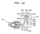
Fig.22 is a structural view showing an oil feed joint-in
socket and air valve of Fig.14;
Fig.23 is a structural view showing an oil feed joint-out
socket of Fig.14;
Fig.24 is a structural view showing a burner and a
vaporizer of Fig.14;
Fig.25 is a structural view showing a heat pump of Fig.14;
Fig.26 is a structural view showing a cooling fin assembly
of Fig.14;
Fig.27 (a) is a view showing an oil feed joint-in and
an oil feed joint-in socket with its air valve abbreviated
in the inserted state of a fuel supply 1 tank of Fig.14, and
(b) is a front view of a socket portion 61;
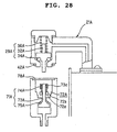
Fig.28 is a view showing an oil feed joint-out and an
oil feed joint-out socket in the inserted state of a fuel
supply 1 tank of Fig.14;
Fig.29 is a front, partly sectional view showing a
kerosene fan heater in accordance with an example 1 of the
third embodiment of the present invention;
Fig.30 is a structural view showing the same liquid fuel
burning apparatus;
Fig.31 is an outline view showing a fuel supply tank
of the same;
Fig.32 is a perspective view showing joining portions
of the fuel supply tank of the same;
Fig.33 is a sectional view showing the structure of an
oil feed joint of the same;
Fig.34 is a sectional view showing the structure of a
return oil joint of the same;
Fig.35 is a sectional view showing the structure of an
oil feed side joining means of the same;
Fig.36 is a sectional view showing the structure of an
oil feed joint socket portion;
Fig.37 is a sectional view showing the structure of a
return oil side joining means of the same;
Fig.38 is a plan view showing a joining means according
to an example 2 of the third embodiment of the present invention;
Fig.39 is a front view of the same;
Fig.40 is a sectional view showing an oil feed joint
side;
Fig.41 is a sectional view showing a return oil joint
side;
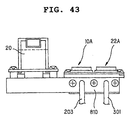
Fig.42 is a sectional view showing a joint socket side;
Fig.43 is a front view of the same;
Fig.44 is a front, partly sectional view showing a
kerosene fan heater in accordance with an example 1 of the
fourth embodiment of the present invention;
Fig.45 is a structural view showing the operation of
the same;
Fig.46 is a partly sectional view of a fuel supply tank
of the same;
Fig.47 is a view cut along a plane B-B in Fig.46;
Fig.48 a partly sectional view showing a suction port
of a fuel supply tank;
Fig.49 is a sectional view showing a filler cap with
a pressure valve for a fuel supply tank;
Fig.50 is a sectional view showing an oil feed joint-in
socket, oil feed joint-out socket and air valve;
Fig.51 is a sectional view showing an air valve;
Fig.52 is a view for explaining insertion of an oil feed
joint-in of a fuel supply tank into an oil feed joint-in socket;
Fig.53 is a sectional view cut along a plane A-A in Fig.44;
Fig.54 is a top view of Fig.53;
Fig.55 is a view for illustrating a state where an oil
feed joint-in of a fuel supply tank is about to fit into an
oil feed joint-in socket;
Fig.56 is a view for illustrating a state where an oil
feed joint-in of a fuel supply tank has fitted into an oil
feed joint-in socket;
Fig.57 is a perspective view showing a fuel supply tank
of an example 2 of the fourth embodiment of the present
invention;
Fig.58 is a top view showing a fuel supply tank of the
same;
Fig.59 is a top view showing the same equipped with an
impact protecting means;
Fig.60 is a top view showing a fuel supply tank of an
example 3 of the fourth embodiment of the present invention;
Fig.61 is a top view showing the same equipped with an
impact protecting means;
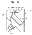
Fig.62 is a top view showing a fuel supply tank of an
example 4 of the fourth embodiment of the present invention;
Fig.63 is a top view showing the same equipped with an
impact protecting means;
Fig.64 is a front, partly sectional view showing a
kerosene fan heater in accordance with an example 1 of the
fifth embodiment of the present invention;
Fig.65 is a structural view showing a liquid fuel burning
apparatus of the same;
Fig.66 is an outline view showing a fuel supply tank
of the same;
Fig.67 is a perspective view showing a joining portion
of a fuel supply tank of the same;
Fig.68 is a sectional view showing the structure of an
oil feed joint of the same;
Fig.69 is a sectional view showing the structure of a
return oil joint of the same;
Fig.70 is a sectional view showing the structure of an
oil feed side joining means of the same;
Fig.71 is a sectional view showing the structure of an
oil feed joint socket portion;
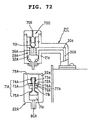
Fig.72 is a sectional view showing the structure of a
return oil side joining means of the same;
Fig.73 is a side view showing a fuel supply tank;
Fig.74 is a sectional view showing the structure of a
filler port of the same;
Fig.75 is a sectional view showing the open state of
a filler port of the same;
Fig.76 is a sectional view showing the relationship
between a fuel supply tank and a placement board;
Fig.77 is a sectional view showing the bottom part of
a fuel supply tank of the same;
Fig.78 is a perspective view showing a water receptacle
attachment hole of a fuel supply tank of the same, viewed
from the tank interior;
Fig.79 is a control circuit of a liquid fuel burning
apparatus of the same;
Fig.80 is a perspective view showing a filler port and
thereabout of a fuel supply tank according to an example 2
of the fifth embodiment of the present invention;
Fig.81 is a side view showing a fuel supply tank of an
example 3 of the fifth embodiment of the present invention;
Fig.82 is a partly sectional view showing a fuel supply
tank of an example 4 of the fifth embodiment of the present
invention;
Fig.83 is a perspective view showing the main body of
kerosene fan heater in accordance with the embodiment of the
present invention;
Fig.84 is a perspective view showing the rear side of
the kerosene fan heater shown in Fig.83;
Fig.85 is an outline view showing the structure of the
liquid fuel burning apparatus shown in Fig.83;
Fig.86 is a front view of the main body shown in Fig.83
with part of the front panel cut away;
Fig.87 is an outline view showing a burner unit and a
vaporizer shown in Fig.83;
Fig.88 is an outline view showing the vaporizer shown
in Fig.87;
Fig.89 is a sectional side view showing a burner unit
in the main body shown in Fig.83;
Fig.90 is a front view showing a burner unit in the main
body shown in Fig.83;
Fig.91 is an outline view showing a fuel supply tank
in Fig.83;
Fig.92 is a top view showing the tank side of the main
body shown in Fig.83;
Fig.93 is an outline view showing an air hole shutoff
means of the fuel supply tank shown in Fig.91;
Fig.94 is an outline view showing a connecting joint
unit of the fuel supply tank shown in Fig.91;
Fig.95 is a sectional view showing the oil feed side
joint in Fig.94;
Fig.96 (a) is an exploded perspective view showing the
assembled state of an oil feed side joint and a suction pipe,
and (b) is a sectional view cut along a plane A-A in (a);
Fig.97 is a sectional view showing the return oil side
joint in Fig.94;
Fig.98 (a) is an exploded perspective view showing the
assembled state of an return oil side joint and a return pipe,
and (b) is a sectional view cut along a plane B-B in (a);
Fig.99 is an outline view showing a filler port shutoff
means of the fuel supply tank shown in Fig.91;
Fig.100 is an outline view showing a water detecting
means and a fuel detecting means in the fuel supply tank shown
in Fig.91;
Fig.101 is an outline view showing a tank insertion
detecting means of a fuel supply tank;
Fig.102 is an outline view showing a detector board on
the fuel supply tank side shown in Fig.86;
Fig.103 (a) is a perspective view showing an electrode
lever on the water receptacle side in the detector board and
(b) is a view showing the attached state of the same;
Fig.104 is a view showing the attached state of an
electrode lever on the tank side in the detector board;
Fig.105 is an outline view showing a tank insertion
detecting means;
Fig.106 is a top view showing a fuel supply tank holding
compartment;
Fig.107 is an exploded perspective view showing assembly
of a tank guide and a tank guide fixture;
Fig.108 is a front view showing a tank guide fixture;
Fig.109 is an exploded perspective view showing the
connected state of a joint socket unit and pipes;
Fig.110 is an outline view showing an oil feed side joint
socket and an air valve on the burner unit side;
Fig.111 is an outline view showing a return oil side
joint socket on the burner unit side;
Fig.112 (a) is a top view showing a connecting joint
socket portion viewed from the air valve side and (b) is an
outline sectional view showing an air valve and a joint socket
portion;
Fig.113 is a view showing the relationship as to the
liquid level of fuel in the fuel supply tank, connecting joint
unit, joint socket unit and air valve;
Fig.114 is a block diagram showing a controller provided
in the main body shown in Fig.83;
Fig.115 is an outline view showing an oil feed side joint
and its joint socket when the tank is inserted in Fig.86;
Fig.116 is an outline view showing an oil feed side joint
and its joint socket when the tank has been fitted in Fig.86;
Fig.117 is an outline view showing a return oil side
joint and its joint socket when the tank is inserted in Fig.86;
Fig.118 is an outline view showing a return oil side
joint and its joint socket when the tank has been fitted in
Fig.86;
Fig.119 is a partly abbreviated, front sectional view
showing a conventional kerosene fan heater;
Fig.120 is an overall sectional side view showing the
same kerosene fan heater; and
Fig. 121 is a partial sectional view showing a fuel supply
tank and a socket of the same.
Best Mode for Carrying Out the Invention
[The first embodiment]
(Example 1)
Fig. 1 is an outline view showing the structure of a liquid
fuel burning apparatus in accordance with the present
invention. As shown in the drawing, a liquid fuel burning
apparatus 1 of the present embodiment is a liquid fuel burning
apparatus of a rotary atomizing type including a vaporizer
B1 for evaporating fuel by heating and a burner unit B integrally
formed with a burner B2 for burning vaporized fuel, further
including a separable fuel supply tank 6 attached to the
apparatus body and an oil feed pump EP for feeding fuel from
fuel supply tank 6 to vaporizer B1, wherein a joining means
C is provided to join fuel supply tank 6, when it is mounted
to the apparatus body, to an oil feed path T, reaching to
burner unit B, so that fuel in fuel supply tank 6 can be directly
fed from oil feed pump EP to burner unit B, instead of providing
a fuel tank for temporarily holding the fuel under fuel supply
tank 6.
Since rotary atomizing burner unit B is of a well-known
structure defined in JIS S3030, the configuration is only
briefly described. Burner unit B is integrally formed of a
vaporizer B1 of a cylinder with a bottom and a burner B2 that
covers the top of vaporizer B1 and mixes vaporized fuel from
vaporizer B1 with primary combustion air and burns the mixture.
Vaporizer B1 includes a front-end piping nozzle of the oil
feed path, exposed through a center hole H formed in the bottom
face of vaporizer B1, and an atomizing motor M and rotor R
for atomizing the fuel flowing out from the nozzle by
centrifugal force. Further, a combustion air passage AP is
connected to the center hole H at the bottom face of vaporizer
B1 so that combustion air can be supplied through combustion
air passage AP by a fan F.
Burner B2 is enclosed by a combustion chamber BR and
is provided with an electrode EL for combustion gas ignition
and a flame rod RD for detecting flame of burner B2 arranged
over burner B2. Other than these components a convection fan,
though it is not illustrated, is arranged over combustion
chamber BR so that air suctioned into the kerosene fan heater
from the room can be blown out together with heated air and
combustion gas inside the combustion chamber BR as warm air
from the air outlet on the front side of the main body.
Fig.2 is a partially sectional, front view showing a
fuel supply tank and Fig.3 is a sectional view showing a joining
means of the same. As illustrated, fuel supply tank 6 has
a vertical box-shaped configuration capable of being inserted
in and removable from the tank holding compartment in the
kerosene fan heater body, and includes a handle 23 arranged
on the top for carriage, a filler cap 24 with a built-in pressure
valve, disposed on the same plane as the handle 23, an oil
gauge 25 disposed near the filler cap 24 with a built-in pressure
valve and extending vertically to make the supplied fuel
visible, an oil feed joint 9 of joining means C for connection
with oil feed path T when fuel supply tank 6 is mounted to
the main body, and a filler port 26 from which filler cap
24 with a built-in pressure valve is loosened to allow
refueling.
As shown in Fig.3, joining means C is composed of an
oil feed joint 9 provided on the fuel supply tank side and
an oil feed joint socket 10 provided for oil feed path T on
the burner unit side. The oil feed joint 9 and oil feed joint
socket 10 are arranged above the maximum fluid level of fuel
in fuel supply tank 6 so as to avoid fuel spilling out of
fuel supply tank 6.
Oil feed joint 9 is arranged along the side face of the
top part of fuel supply tank 6 and enclosed by a protective
cover 28 for protection against impacts, and is attached to
an attachment plate 27 by the protective cover 28. Further,
the oil feed joint incorporates a valve mechanism 30 of a
spindle type therein and is connected to a suction pipe 31
for suctioning fuel from fuel supply tank 6 and sending fuel
to electromagnetic pump EP for conveyance.
Suction pipe 31 has one end almost reaching the bottom
of fuel supply tank 6 while the other side is formed so as
to penetrate through the top face of fuel supply tank 6 and
is bent in an approximately inverted U shape so that the distal
end is connected to communicate with valve mechanism 30 of
the oil feed joint. Protective cover 28 is formed so as to
enclose the projected part of suction pipe 31 over the top
face of fuel supply tank 6, i.e., the approximately, inverted
U-shaped communicating portion of suction pipe 31, as well
as protecting oil feed joint 9.
Valve mechanism 30 of oil feed joint 9 is comprised of
a joint body 33, a valve element 34, an annular O-ring packing
35, a spring 36 and a joint body packing 37. Joint body 33
is formed in a funnel shape by enlarging a metallic pipe in
diameter and formed at a partway position with a bead portion
33d which is extended in a flange-like manner for allowing
joint body 33 to fit inside cover 28. That is, the joint body
is continuously formed of a cylindrical barrel portion 33a,
a tapered portion (sealing surface) 33b which gradually
becomes smaller in diameter from the lower end of the barrel
downwards, and a cylindrical portion 33c having a
predetermined length with a constant diameter equal to the
predetermined diameter at the lower end of the tapered portion
33b while the lower end of cylindrical portion 33c is tapered
so as to be further smaller in diameter. Formed at the upper
end of joint body 33 is an inward flange 33e. This flange
fixes joint body packing 37, which in turn holds suction pipe
31 so that its front end is inserted into the joint body,
establishing communication.
Here, the material of joint body 33 should not be limited
to metal but may be a resin. Barrel portion 33a, tapered
portion 33b, cylindrical portion 33c and other parts should
not be limited to having circular shapes. Joint body packing
37 is molded and shaped from rubber, providing the sealing
function for joint body 33 and the contact sealing function
with suction pipe 31.
Valve element 34 has a shape approximately analogous
to the inside shape of the funnel-like portion of joint body
33 and has a configuration which can reciprocate inside joint
body 33. Specifically, the valve element is comprised of a
plug portion (sealing surface) 34a having an approximately
conical shape and an elongated column-like movable portion
34b which is extended from the lower end of plug portion 34a
and is narrower and longer than cylindrical portion 33c. An
annular O-ring packing 35 is provided at the tapered portion
of plug portion 34a so that the packing will be able to come
into sealing contact with tapered portion 33b of joint body
33.
In order to regulate contact and separation between plug
portion 34a and tapered portion 33b of joint body 33, the
length of movable portion 34b is designated so that its front
end projects out from the cylindrical portion 33c when the
valve is closed or when O-ring 35 of plug portion 34a is placed
in sealing contact with the inner surface of tapered portion
33b.
The aforementioned spring 36 is interposed between the
top inward flange 33e and plug portion 34a of valve element
34, inside barrel portion 33a of joint body 33, so as to urge
valve element 34 in the valve closing direction.
Attachment plate 27 is welded to the side face of fuel
supply tank 6 and is comprised of a box-like fixing portion
27a for fixing impact protective cover 28 and an insert guide
portion 27b disposed at a lower position, serving as a guide
means when fuel supply tank 6 is inserted.
Oil feed joint socket 10 includes: a cylindrical valve
retainer body 62 having a projection 60 at the center thereof
for engagement with the valve element 34 of oil feed joint
9 and an annular groove 69 around the projection for creating
communication with oil feed path T; a cylindrical,
bellows-like joint sealing element 63 formed of rubber in
such a manner that it projects upwards from valve retainer
body 62 and encloses the projection 60; a spring 64 interposed
between the top part of the sealing element and valve retainer
body 62 so as to urge the sealing element upwards to assist
its flexibility; and a bracing plate 66 for fixing the bottom
of sealing element 63 against valve retainer body 62. Formed
at the top of sealing element 63 is a passage hole 70 into
which valve element 34 on the oil feed joint side snugly fits.
Oil feed joint socket 10 is fixed by an oil feed joint
support plate 72 to tank guide 71 which sections the tank
holding compartment in the apparatus body. Oil feed joint
support plate 72 is bent and formed in a U-shape with its
top open and has oil feed joint socket 10 fixed to the bottom
plate thereof and one side plate fixed to tank guide 71.
Another side plate 73 of support plate 72, bent on the other
side (tank side) is rounded at its front end so as to form
a guide portion 74 for insertion of fuel supply tank 6 into
the main body. Provided on the tank guide side of support
plate 72 is an elastic guide abutment plate 75 which is rounded
or convexed toward the fuel supply tank side. This guide
abutment plate 75 is fixed at only its upper side and provides
the guiding function of smoothing the connection between oil
feed joint 9 and its joint socket 10 by its abutting protective
cover 28 of oil feed joint 9 when fuel supply tank 6 is inserted
into the main body.
Fig.4 is a sectional view showing a fixing structure
of the lower end of a suction pipe. Suction pipe 31 almost
reaches the bottom of fuel supply tank 6 opposite to that
with handle 23 and has a suction opening 44 at its distal
end. A filter 45 which blocks water and dust from permeating
is fitted inside this suction opening 44. This suction opening
44 may be formed at the bottom face instead of the side portion
of the distal part of suction pipe 31. This suction pipe 31
is assembled into fuel supply tank 6 in such a manner that,
before the left and right parts of fuel supply tank 6 is
Adrian-formed, filter 45 is fitted into suction opening 44
and suction pipe 31 is fitted through a cutout hole 46a formed
in a crank-shaped, suction pipe fixing plate 46, and then
the left and right parts of fuel supply tank 6 are joined
by Adrian-forming. Since the thus configured suction pipe
31 is kept from moving during carriage of fuel supply tank
6 by suction pipe fixing plate 46, suction opening 44 of suction
pipe 31 will not interfere with the inner wall of fuel supply
tank 6 so that it is possible to avoid damage to it.
Fig.5 is a sectional view showing a filler cap with a
built-in pressure valve for the fuel supply tank. Filler cap
24 with a built-in pressure valve is comprised of a cap 53
which is screw fitted on filler port 26 which is projectively
formed on the top of fuel supply tank 6 with its outer periphery
threaded and a pressure valve mechanism 54. The filler cap
is screw fitted on filler port 26 with a rubber packing 55
interposed therebetween. This cap 53 has a pressure releasing
hole 56 for relieving pressure, penetrating through the center
thereof. The side of the cap is threaded and the brim is curled.
Rubber packing 55 provides a sealing function between filler
port 26 and cap 53 and has a pressure releasing hole 57 at
the center thereof for relieving pressure.
Pressure valve mechanism 54 is composed of a valve element
58 disposed between rubber packing 55 and the ceiling of cap
53 and a spring 59 urging this valve element 58 so as to close
pressure releasing hole 52. The reason why this pressure valve
mechanism 54 is needed is as follows. Generally, fuel to be
charged into fuel supply tank 6 is stored at a cool site,
and after fuel supply tank 6 is refueled, it is used in a
room where the temperature is higher. Therefore, the
temperature around fuel supply tank 6 inside main body 1 is
high so that the space of air other than the fuel inside fuel
supply tank 6 will expand due to difference in temperature.
Resultantly, the air pressure increases, causing the liquid
surface of fuel in tank 6 to rise and producing a risk of
fuel spilling out. To avoid this, pressure valve mechanism
54 is provided. On the contrary, in order to prevent
occurrence of negative pressure in the fuel supply tank,
through- holes 77 and 78 having a diameter equal to or smaller
than 1.5 mm are formed in rubber packing 55 and the ceiling
of cap 53.
As shown in Fig.1, arranged along oil feed path T from
oil feed joint socket 10 to the burner unit are electromagnetic
pump EP as an oil feed pump for feeding the fuel to burner
unit B and electromagnetic valve EV as a shutoff valve for
shutting off fuel supply. Solenoid pump EP and
electromagnetic BEN 80 may be provided separately, though
the two are integrally arranged in oil feed path T, in the
case of the present embodiment.
Fig.6 is a sectional view showing an integrated state
of electromagnetic pump EP and electromagnetic valve EV. As
illustrated, electromagnetic valve EV is comprised of a
cylindrical valve body EV1, a cylindrical valve piece EV4
incorporated in a valve chamber EV2 of valve body EV1 and
having an O-ring or rubber sheet EV7 at the end for opening
and closing a communication path EV3 with electromagnetic
pump EP, a solenoid coil EV5 arranged around valve body EV1
for causing valve piece EV4 to move in the valve opening
direction and a coil spring EV6 interposed between the exit
side of valve chamber EV2 and valve piece 42 for urging valve
piece EV4 to move in the valve closing direction.
A mating hollow EV8 which receives electromagnetic pump
EP is formed so as to be connected to the entrance side of
valve chamber EV1 by way of communication passage EV3. An
exit side projection P of electromagnetic pump EP is adapted
to tightly fit this hollow EV8 with an O-ring OR therebetween.
A pipe connecting port TC1 is formed on the exit side of the
valve chamber of electromagnetic valve EV while another pipe
connecting port TC2 is formed on the entrance side of
electromagnetic pump EP.
An oil feed pipe T1 connecting this electromagnetic pump
EP with oil feed joint socket 10 and another oil feed pipe
T2 connecting the connecting port TC1 of electromagnetic valve
EV with vaporizer B1 are formed of copper pipes, thereby forming
oil feed path T. Oil feed pipe T1 connecting oil feed joint
socket 10 and electromagnetic pump EP may be of a resin pipe.
In the kerosene fan heater thus configured, when fuel
in fuel supply tank 6 has run out, fuel is charged into fuel
supply tank 6 through filler port 26 by opening the lid of
main body 1, taking out fuel supply tank 6 by holding handle
23, releasing and removing filler cap 24 with a pressure valve
with the handle 23 side up. In this case, since refueling
is done while fuel supply tank 6 is placed on a flat site
with the handle 23 side up, it is no longer necessary to turn
fuel supply tank 6 upside down. Accordingly, it is possible
to easily and reliably perform refueling without the filler
cap of fuel supply tank 6 being stained with fuel.
When refueling is completed, the fuel supply tank 6 filled
up with fuel is set into the predetermined position inside
main body 1 after opening the lid of main body 1. Upon this
setting, insert guide portion 27a extended downwards of
attachment plate 27 is guided between insert guide 74 extended
upwards of oil feed joint support plate 72 and valve retainer
body 62, and protective cover 28 of fuel supply tank 6 is
pushed by guide abutment sheet 75 so that valve element 34
of oil feed joint 9 is lead and inserted into passage hole
70 of oil feed joint socket 10. As the valve element is inserted,
the bellows of sealing element 63 contracts, whereby valve
element 34 of oil feed joint 9 comes into contact with projection
60 of valve retainer body 62.
When fuel supply tank 6 is further inserted into main
body 1, valve element 34 of oil feed joint 9 moves upwards,
pressurizing spring 36, whereby valve element 34 becomes open.
That is, the oil feed path from suction pipe 31 of fuel supply
tank 6 to the electromagnetic pump EP side of oil feed path
T by way of joining means C becomes open.
When, in this tank inserted state, the operation switch
(not shown) of the kerosene fan heater is actuated so as to
turn the power on, solenoid EV5 of electromagnetic valve EV
is magnetized so that valve piece EV4 moves in the valve opening
direction, whereby the oil feed path T from electromagnetic
pump EP to the vaporizer B1 side is opened and fuel is sent
by electromagnetic pump EP to the vaporizer B1 side.
At vaporizer B1, fuel fed from electromagnetic pump EP
is atomized and evaporated by rotor R of centrifugal atomizer,
the vapor is ejected from the flame port of burner B2 located
above, and ignited at the flame port and burns in the combustion
chamber. At the same time, based on the difference in
temperature between the room temperature detected by the room
temperature thermistor and the set temperature designated
through the control portion, an unillustrated controller
controls drive of electromagnetic pump EP to vary the amount
of liquid fuel fed to vaporizer B1, whereby the heat generation
rate of the burning is controlled appropriately.
When combustion starts and the flame sensor detects a
flame current equal to or greater than the preset current
value, an unillustrated fan motor is activated so that the
blower fan starts rotating to suction air from the room. The
rotational rate of the fan is controlled by the controller.
The air suctioned from the room absorbs the radiated heat
obtained in combustion chamber BR and is blown out together
with the combustion gas as warm air through the air outlet
to the room, whereby the temperature in the room rises and
is controlled.
When the operation of main body 1 is stopped, drive of
electromagnetic pump EP is deactivated and electromagnetic
valve EV is demagnetized so as to close the valve, whereby
fuel supply can be shut off in a positive manner.
(Example 2)
Fig.7 is an outline view showing the structure of a liquid
fuel burning apparatus in accordance with an example 2. In
this example, an electromagnetic valve EV for shutting off
fuel supply is disposed closer to the oil feed joint socket
10 side than electromagnetic pump EP is. Also in this case,
it is possible to achieve space-saving and simplification
of the pipe connecting process by integrating electromagnetic
valve EV and electromagnetic pump EP. Other configurations
are the same as those in example 1, so that the description
is omitted.
(Example 3)
Fig.8 is an outline view showing the structure of a liquid
fuel burning apparatus in accordance with an example 3. In
this example, an electromagnetic pump EP is arranged on the
suction pipe 31 side upstream of oil feed joint 9 of fuel
supply tank 6 and is fixed to the top face of fuel supply
tank 6 by screws or the like. The suctioning side of this
electromagnetic pump EP is connected for communication to
suction pipe 31 while the ejection side is connected for
communication to oil feed joint 9 by a pipe. Electromagnetic
valve EV is arranged halfway along oil feed path T between
oil feed joint socket 10 and vaporizer B1 similarly to the
first embodiment.
Also in the above configuration, once fuel supply tank
6 is set in place into the main body, oil feed joint 9 and
joint socket 10 are connected establishing the oil feed path
from fuel supply tank 6 to vaporizer B1, whereby it is possible
for electromagnetic pump EP to feed fuel to the vaporizer.
Here, concerning electric power supply to the
electromagnetic pump, an unillustrated connecting plug can
be used to be connected to the main body side when detachable
fuel supply tank 6 is set into the main body. Other
configurations are the same as those in example 1, so that
the description is omitted.
(Example 4)
Fig.9 is an outline view showing the structure of a liquid
fuel burning apparatus in accordance with an example 4; Fig.10
is a sectional view showing an oil feed joint socket of the
same; and Fig.11 is a structural sectional view showing an
air valve of the same. In this example, as a shutoff valve
for shutting off fuel supply, an air valve 110 is used in
place of the electromagnetic valve EV used in the above
embodiments 1 to 3. This air valve 110 is arranged in oil
feed joint socket 10.
Air valve 110 is to take in air to feed air for shutting
off the oil feed path of fuel from fuel supply tank 6 to
electromagnetic pump 13, and is disposed in a communication
passage 112, which is branched off from oil feed path T connected
for communication from groove 69 of oil feed joint 9b and
the burner unit B·side. Further, similarly to oil feed joint
socket 10, air valve 110 is arranged above the maximum liquid
surface of fuel in fuel supply tank 6, so as to prevent fuel
from spilling out of fuel supply tank 6.
As shown in Fig.11, the structure of air valve 110 is
composed of a cylindrical valve body 115 having an opening
113 on one side thereof which opens to the atmosphere and
a valve chamber 114 on the other side which is connected to
the communication passage 112, an approximately conical valve
piece 116 for opening and closing the opening 113 arranged
in valve chamber 114 of valve body 115, a solenoid coil 117
arranged around valve body 115 to move the valve piece 116
in the valve opening direction, a coil spring 118 interposed
between the opening side of valve chamber 114 and valve piece
116 for urging valve piece 116 in the valve closing direction,
and an O-ring 119 disposed on the sealing side of valve piece
116.
This air valve 110 is closed by activation of solenoid
coil 117 while kerosene fan heater is being operated, under
control of an unillustrated controller. While the kerosene
fan heater is not in operation, solenoid coil 117 is
demagnetized so that the valve is opened by the repulsive
force of spring 118, whereby air for shutting off fuel in
oil feed path T from fuel supply tank 6 to electromagnetic
pump EP is taken in to oil feed path T. Here, control, or
opening and closing of air valve 110 may be done mechanically
or manually other than the above electric control.
Similarly to the above examples 1 and 2, electromagnetic
pump EP is arranged closer to the burner unit B side downstream
of oil feed joint 9b.
In the above configuration, when oil feed tank 6 is mounted
to the main body, oil feed joint 9 and joint socket 10 mate
each other creating an oil feed path from fuel supply tank
6 to vaporizer B1, whereby it is possible to feed fuel to
vaporizer B1 by electromagnetic pump EP. When fuel supply
needs to be shut off, air valve 110 is opened so that air
can be taken in to oil feed path T, whereby it is possible
to stop fuel supply from fuel supply tank 6. Other
configurations and operations are the same as those in example
1, so that the description is omitted.
(Example 5 )
Fig.12 is an outline view showing the structure of a
liquid fuel burning apparatus in accordance with an example
5. In this example, similarly to example 3, an electromagnetic
pump EP is disposed close to suction pipe 31 upstream of oil
feed joint 9 on the fuel supply tank 6 side and similarly
to embodiment 4, an air valve 110 is used as a shutoff valve
for shutting off fuel supply and is arranged in oil feed joint
socket 10. The configurations and operations are same as those
in examples 3 and 4 so that the description is omitted.
(Other examples)
The present invention should not be limited to the above
embodiments and many changes and modifications can of course
be added within the scope of the present invention. For
example, though description of the above embodiment was made
referring to the oil supply system in a rotary atomizing type
liquid fuel burning apparatus, the present invention can of
course be applied to other burning types than this, such as
pot type, pressure spraying type, jet spraying type burners
and others.
Concerning the oil feed pump, it should not be limited
to electromagnetic pumps, but pumps of other types can be
used as long as it can feed fuel. As an example of the closing
means for closing the filler opening of the fuel supply tank,
a filler cap screw-fitted on the filler opening was mentioned,
but a rotational shutoff type filler cap may be used. Further,
the above embodiment was described referring to a
configuration that uses a filler cap with a built-in pressure
valve, but the pressure valve mechanism may be provided in
the oil feed joining portion, not limited to the filler cap.
In the above embodiment, the valve mechanism that opens
its valve when the fuel supply tank is set in the main body
and closes the valve when the tank is removed is provided
in the oil feed joint only. However, a similar valve mechanism
may also be provided on the oil feed joint socket side.
As described heretofore, according to the present
invention, in a liquid fuel burning apparatus of a rotary
atomizing type, pot type, pressure spraying type, jet spraying
type, or other burning types, a joining means for connecting
the fuel supply tank to the oil feed path reaching the burner
when the fuel supply tank is set into the apparatus body is
provided without providing a fuel tank for temporarily holding
fuel under the fuel supply tank, so that fuel is directly
fed from the fuel supply tank to an oil feed pump which feeds
the fuel to the burner unit. Accordingly, it is possible to
construct the fuel passage with fewer components. Further,
since setting and refueling of the fuel supply tank can be
done without turning the fuel supply tank upside down, the
fuel supply tank becomes easy to handle.
[The second embodiment]
The embodiment of the present invention will be described
with reference to the drawings. Fig.13 is a front overall
view showing a kerosene fan heater including a liquid fuel
burning apparatus in accordance with the embodiment. Fig.14
is an outline view showing the liquid fuel burning apparatus.
A kerosene fan heater body 1 is comprised of a detachable
front panel 2, a top panel 3 integrally formed with side panels,
a control portion 4 allowing for operation control, an outlet
port 5 from which warm air is blown out, and an openable and
closable lid 7 arranged at the right side in the top of top
panel 3 for permitting a fuel supply tank 6 to be fitted in
and taken out, and is placed and fixed on a mount base 8 for
holding liquid fuel in case of leakage. As shown in Figs.13
and 14, main body 1 incorporates detachable fuel supply tank
6 for temporarily storing fuel, a vaporizer 12 for vaporizing
the liquid, an electromagnetic pump 13 for feeding fuel from
fuel supply tank 6 to vaporizer 12, a burner 14 for mixing
vaporized fuel through vaporizer 12 with primary combustion
air and burning the mixture, a combustion chamber 15 enclosing
burner 14, a partition 16 for partitioning burner 14 and
combustion chamber 15, a burner box 17 for holding burner
14, a heat pipe 18 for retaining fuel from vaporizer 12 and
a cooling fin assembly 19 located between vaporizer 12 and
heat pipe 18 to cool fuel.
The fuel supply tank 6 includes, as shown in Fig.15,
a handle 23 for carriage, a filler cap 24 with a built-in
pressure valve, an oil gauge 25, a filler port 26, an oil
feed joint 9A having avalve for opening and closing the passage
connected to a pipe for suctioning fuel, and an oil feed
joint-out 21A for transporting the return fuel from the
vaporizer, from heat pipe 18 to fuel supply tank 6. Fig.16
is a structural view of the fuel supply tank 6 viewed in
perspective from a higher point. This fuel supply tank 6 is
configured so as to be attached and detached. The oil feed
joint-in 9A and the oil feed joint-out 21A are configured
so as to be attached to and detached from the oil feed joint-in
socket 10A and the oil feed joint-out socket 22A, respectively.
As shown in Figs.15 and 18, the oil feed joint-in 9A
is provided with a spindle type valve mechanism 28A and a
suction pipe 27A for suctioning fuel from the fuel supply
tank 6 while the oil feed joint-out 21A is provided with a
spindle type valve mechanism 29A and a return pipe 30A for
returning the liquefied fuel into the fuel supply tank 6.
The oil feed joint-in 9A is fixed to the fuel supply tank
6 with a rubber packing 50A interposed therebetween by a screw
bolt inserted into an attachment hole 47A formed on the oil
feed joint 9 in the fuel supply tank 6.
As shown in Fig. 17, the valve mechanism 28A is comprised
of a valve element 31A having a projection, an annular O-ring
packing 33A and a spring 35A, and is fitted into the hollow
of a guard 300A that has a passage hole at the hollow bottom,
and covered by a lid nut 39A which is fixed to the guard with
a seal packing 37A therebetween. The projected part of valve
element 31A is fitted in the passage hole formed at the hollow
bottom of the guard 300A with the aforementioned O-ring packing
33A held therebetween. Spring 35A is interposed in a space
302A between the top part of the valve element 31A and the
lid nut 39A. A passage 43A for supplying fuel to the space
302A is provided and connected to the suction pipe 27A for
suctioning fuel from fuel supply tank 6.
As shown in Fig.18, the suction pipe 27A is extended
to almost the bottom of the fuel supply tank 6, penetrating
through a fitting hole 46A formed on the top face of the fuel
supply tank 6, and has a suction opening 44A and a filter
45A at its distal end. This suction opening 44A may be formed
at the side portion other than the front end part of the suction
pipe 27A.
As shown in Figs.19 and 20, the valve mechanism 29A is
comprised of a valve element 32A having a projection, an annular
O-ring packing 34A and spring 36A, and is fitted in the hollow
of a guard 301A with a passage hole at the hollow bottom and
is covered by a lid nut 40A which is fixed to the guard with
a seal packing 38A therebetween. The projected part of valve
element 32A is fitted in the passage hole formed at the hollow
bottom of the guard 301A with the aforementioned O-ring packing
34A held therebetween. The spring 36A is interposed in a space
303A between the top part of the valve element 32A and the
lid nut 40A. Further, the aforementioned return pipe 30A for
returning fuel into the fuel supply tank 6 is disposed so
as to communicate with the space 303A. The oil feed joint-out
21A is fixed to the fuel supply tank 6 with a rubber packing
51A therebetween by a screw bolt inserted into an attachment
hole 49A formed on the oil feed joint 21 side in the fuel
supply tank 6. Further, a fitting hole 48A through which the
return pipe 30A is inserted is formed in the fuel supply tank
6.
Filler cap 24 with a built-in pressure valve (Fig.13)
arranged on the top face of fuel supply tank 6 is composed
of, as shown in Fig.21, a filler port 26 of which the outer
periphery is threaded, a cap 53 screw fitted on the filler
port 26 with a rubber packing 55 providing a sealing function
interposed therebetween and a pressure valve mechanism 54.
The aforementioned filler port 26 is comprised of a hole 306A
opening on the same plane as that to which the oil feed joint-out
21A is attached and a wall portion 26a projected outwards
from the rim of the hole 306A. The cap 53 is fitted on the
projected filler port 26 and engaged with wall portion 26a.
Here, the side face of the cap 53 and the wall portion 26a
are shaped so as to mesh each other. Fig.21 shows a particular
example in which they are shaped in a wavy form. The pressure
valve mechanism 54 is comprised of a valve element 58 and
a spring 59, and the rubber packing 55 and the cap 53 have,
at their center, pressure relieve holes 56 and 57 for releasing
pressure, respectively.
The oil feed joint-in socket 10A (Fig.13) is comprised
of, as shown in Fig.22, a valve mechanism 60A for receiving
the valve element 31A of the valve mechanism 28A (Fig.17),
a guard 68A and a valve support 61A having a grating hole
66A fitted in the guard. The valve mechanism 60A is composed
of a valve element 62A, a spring 63A and a sealing O-ring
64A. The aforementioned valve support 61A serves as a stopper
for valve element 62A. That is, when the oil feed joint-in
9A(Fig.16) is fitted to the oil feed joint-in socket 10A,
side part 62a of the valve element 62A is supported by a valve
abutment 65A of the valve support 61A. Further, oil feed
joint-in socket 10A includes a sealing surface 67A creating
a seal with valve mechanism 28A of oil feed joint-in 9A, a
passage 69A extending from grating hole 66A of valve support
61A to electromagnetic pump 13 and a passage 70A which branches
off at a position partway along the passage and communicates
with air valve 20 formed of an electromagnetic coil and other
components.
The oil feed joint-out socket 22A (Fig.16) is comprised
of, as shown in Fig.23, a valve mechanism 71A for receiving
the valve element 32A of the valve mechanism 29A (Fig.20),
a guard 79A and a valve support 72A having a grating hole
77A fitted in the guard 79A. The valve mechanism 71A is
composed of a valve element 73A, a spring 74A and a sealing
O-ring 75A. The aforementioned valve support 72A serves as
a stopper for valve element 73A. That is, when the oil feed
joint-out 21A (Fig.16) is fitted into the guard 79A of the
oil feed joint-out socket 22A, the side part 73a of the valve
element 73A is supported by a valve abutment 72a of the valve
support 72A.
When the fuel supply tank 6 is set to the main body 1
by the above structure, the joining means, namely the valve
mechanism 28A of the oil feed joint-in 9A and the valve mechanism
29A of the oil feed joint-out 21A are set in place to oil
feed joint-in socket 10A and oil feed joint-out socket 22A,
respectively. The external O-rings 41A (Fig.17) and 42A
(Fig.19) of the valve mechanisms 28A and 29A abut the sealing
surface 67A (Fig.22) of the oil feed joint-in socket 10A and
the sealing surface 78A (Fig.23) of the oil feed joint-out
socket 22A, creating sealing contact.
The air valve 20 (Fig.22) is closed during operation,
whereby the electromagnetic pump 13 (Figs.13 and 14) feeds
liquid fuel from the fuel supply tank 6 to the vaporizer 12.
It is opened when the apparatus is not in operation. Further,
when the vaporizer 12 is to be baked for cleaning, the air
valve 20 is opened and the electromagnetic pump 13 is actuated
so as to send air to the vaporizer 12.
(Vaporizer and burner configuration)
Fig.24 is a structural view showing a vaporizer and a
burner portion. As illustrated, vaporizer 12 is comprised
of a vaporizing element 81 for vaporizing the fuel existing
therein by heating, anozzle 82 for ejecting the fuel evaporated
by this vaporizing element 81, a needle 83 that reciprocates
back and forth through the hole of the nozzle 82 so as to
open and close it, a solenoid valve 84 that is coupled with
this needle 83 for moving needle 83, a fuel entrance 85 for
supplying fuel to vaporizing element 81, a return circuit
86 for returning the fuel inside vaporizer 12 when the operation
stops and a heat collector 87 for collecting combustion heat
from burner 14.
Vaporizing element 81 is a sintered cylinder made of
fine ceramic particles, and tar generated when fuel evaporates
accumulates inside vaporizing element 81 from its surface
inwards. Fuel entrance 85 to vaporizer 12 has a double pipe
structure of an outer stainless pipe 88 and an inner copper
pipe 89. Stainless pipe 88 is used to reduce heat conduction
from vaporizer 12 and suppress temperature rise of fuel
entering vaporizer 12. Further, stainless pipe 88 is made
greater in diameter than the copper pipe so as to further
inhibit heat conduction from stainless pipe 88 to the copper
pipe. The end of copper pipe 89 is located at a position outside
vaporizer 12.
Solenoid valve 84 is mainly composed of an
electromagnetic coil 90 made up of wire wound in a coil, a
moving piece 91 which is located inside the coil and axially
movable together with the needle, an attracting piece 92 and
a pressure spring 93. As electric current through
electromagnetic coil 90 is turned on or cut off, moving piece
91 is attracted to or departs from attracting piece 92, so
as to cause needle 83 linked with moving piece 91 to move
whereby the hole of nozzle 82 of vaporizer 12 is made open
or closed.
Burner 14 is composed of a mixing tube 94 for mixing
the combustion gas evaporated through vaporizer 12 with
primary combustion air and a flame port 95 for burning the
mixed combustion gas.
(Configurations of the electromagnetic pump, collecting
container, cooling fin assembly)
As shown in Fig.14, electromagnetic pump 13 suctions
fuel from fuel supply tank 6 to send it toward the vaporizer
12 while the ejected amount of fuel and the like are controlled
by the controller.
Fig.25 is a sectional view showing a collecting container.
A collecting container 18 is configured as illustrated, and
is provided to temporarily retain and cool the fuel, which
remains inside vaporizer 12 upon a halt of electromagnetic
pump 13 and shutoff of nozzle 82 of vaporizer 12 because of
room temperature control from the start to end of operation
and needs to be returned to fuel supply tank 6.
A container body 96 of collecting container 18 is tightly
sealed and its volume is designated to be about 20 cc. As
stated already, the partly evaporated fuel remaining in
vaporizer 12 becomes liquefied when it is returned to fuel
supply tank 6. This unburned, returned fuel roughly amounts
to 0.3 to 0.5 cc each time. If it is assumed that
electromagnetic pump 13 is halted roughly ten times to change
the burning intensity under room temperature control when
the kerosene fan heater is operated all day long, the amount
of returned unburned fuel per day amounts to about 3 to 5
cc. Accordingly, container body 96 has a large enough volume
(about 20 cc) to collect the amount of returned fuel.
Formed on the side face of this container body 96 is
an entrance 97 of combustion gas from vaporizer 12 while an
exit 98 for the fuel collected in container body 96 is formed
on the top of container body 96. A pipe 99 almost reaching
the bottom inside container body 96 is arranged through this
exit 98 on the container top and is formed with a funnel shaped
suction port 200 at its lower end so that the fuel collected
inside the container will be suctioned easily without being
affected by its surface tension.
Fig.26 is a sectional view showing a cooling fin assembly
19 provided halfway along the passage between vaporizer 12
and collecting container 18. As illustrated, cooling fin
assembly 19 has many thin fins 201 formed on the outer side
of pipe 202 and has the function of radiating heat from partly
evaporated fuel, which is returned from vaporizer 12.
In the above configuration, oil feed pipes 203, 204,
205, 206 and 207, which each connect the oil feed joint-in
socket 10A and the electromagnetic pump 13, the
electromagnetic pump 13 and the vaporizer 12, the vaporizer
12 and the cooling fin assembly 19, the cooling fin assembly
19 and the heat pipe 18, and the heat pipe 18 and the oil
feed joint-in socket 10A, respectively, are formed of steel
pipes.
Concerning the above configuration, its operation will
be described.
When fuel in the fuel supply tank 6 (Fig.13) has run
out, fuel is charged into fuel supply tank 6 through the filler
port 26 by opening the lid 7 of the main body 1, taking out
the fuel supply tank 6 by holding the handle 23, releasing
and removing the filler cap 24 with a pressure valve with
the handle 23 side up. When refueling is completed, the fuel
supply tank 6 filled up with fuel is set into the predetermined
position inside the main body 1 after opening the lid 7 of
the main body 1. Upon this setting, when, as shown in Figs.27
and 28, the valve element 31A in the valve mechanism 28A of
the oil feed joint-in 9A and the valve element 32A in the
valve mechanism 29A of the oil feed joint-out 21A, as the
joining means of the fuel supply tank 6, respectively press
the valve element 62A of the valve mechanism 60A of the oil
feed joint-in socket 10A and the valve element 73A of the
valve mechanism 71A of the oil feed joint-out socket 22A,
as the joining means, the valve elements 62A and 73A move
down so that the side parts 62a and 73a of the valve elements
62A and 73A abut bearing portions 65A and 72a of valve supports
61A and 72A. Then the valve element 31A of the valve mechanism
28A of the oil feed joint-in 9A and the valve element 32A
of the valve mechanism 29A of oil feed joint-out 21A move
upwards so that the urging springs 35A and 36A become compressed,
whereby the O- ring packings 33A and 34A forming sealing
surfaces of valve elements 31A and 32A depart from the
respective sealing surfaces of the oil feed joint-in 9A and
the oil feed joint-out 21A, creating clearances. Thus, these
clearances establish the passage of fuel into the
electromagnetic pump 13 side and the passage from the heat
pump 18 to the fuel supply tank 6.
Next, electric power is turned on by actuating the
operating switch (not shown) of the kerosene fan heater, the
vaporizer heater (not shown) attached to the vaporizer 12
heats the vaporizer 12. During heating, a vaporizer
thermistor (not shown) detects the temperature of vaporizer
12. When the vaporizer 12 is heated to a predetermined
temperature, the electromagnetic pump 13 is driven so as to
suction the liquid fuel inside the fuel supply tank 6 through
the suction pipe 27A and sends it to the vaporizer 12 by way
of the oil feed joint-in 9A and the oil feed joint-in socket
10A. The liquid fuel is gasified by the heated vaporizer 12
and the gas is ejected from the flame port 95 of the burner
14, ignited at the flame port 95 and burns in the combustion
chamber. At the same time, based on the difference in
temperature between the room temperature detected by the room
temperature thermistor and the set temperature designated
through the control portion, a controller controls drive of
the electromagnetic pump 13 to vary the amount of liquid fuel
fed to vaporizer 12, whereby the heat generation rate of the
burning is controlled appropriately.
When combustion starts and the flame sensor detects a
flame current equal to or greater than the preset current
value, a fan motor is activated so that the blower fan starts
rotating to suction air from the room. The rotational rate
of the fan is controlled by the aforementioned controller.
The air suctioned from the room absorbs the radiated heat
in combustion chamber 15 and is blown out together with the
combustion gas as warm air through the air outlet 5 to the
outside (the room of main body 1), whereby the temperature
in the room will rise.
Next, when the operation of main body 1 is stopped, the
drive of electromagnetic pump 13 is deactivated and electric
current through the vaporizer heater is stopped. At the same
time, the solenoid valve 84 is deactivated so as to release
the moving piece 91 and the attracting piece 92, whereby the
hole of the nozzle 82 is shut off by the needle 83. As the
hole is closed, partially evaporated fuel remaining inside
the vaporizer 12 passes through the return channel 86 (Fig.24)
and oil feed pipe 205 (Fig.14) to the heat pump 18, where
the fuel is stored. The partly evaporated fuel, elevated in
temperature, is cooled through the cooling fin assembly 19
provided between the oil feed pipe 205 and the oil feed pipe
206 and sent to the heat pipe 18. The partly evaporated fuel
fed into the heat pipe 18 reduces in temperature with the
passage of time, whereby the gas is liquefied and stored therein.
Upon ignition, the nozzle 82 is closed (for about one to two
minutes) until the fuel changes from liquid to gas inside
the vaporizer 12, whereby the internal pressure in the
vaporizer 12 rises to about 0.2 kg/cm. This pressure acts
on the interior of the heat pipe 18 so as to push up the liquid
inside the heat pipe 18 and send it out from the funnel shaped
port 200 at the lower end of the pipe 99 (Fig.25) arranged
inside the heat pipe 18 through the oil feed pipe 207 (Fig.14),
the passage 80A (Fig.23) of the oil feed joint-out socket
22A and the return pipe 30A (Fig.20) of oil feed joint-out
21A into the fuel supply tank 6.
When liquid fuel is heated and evaporated in the vaporizer
12, it leaves some impurities therein. The impurities build
up inside the vaporizer 12 after long-term operation, whereby
the amount of gas emitted from the nozzle 82 of the vaporizer
12 lowers and it becomes necessary to remove the impurities
built up inside the vaporizer 12. For this purpose, the
vaporizer 12 is cleaned by baking in the following manner.
When the switch for cleaning by baking is turned on with the
fuel supply tank 6 set in the main body 1, the temperature
of vaporizer 12 is raised automatically to a temperature for
cleaning by baking. At the same time, the air valve 20 (Fig.14)
is activated so as to open itself and electromagnetic pump
13 starts to be driven. In this situation, since the pressure
of air entering through the air valve 20 is higher than that
inside the fuel supply tank 6, air is suctioned through the
air valve 20 and is sent by the electromagnetic pump 13 to
the vaporizer 12. Thus, the impurities in vaporizer 12 can
be baked for a predetermined time together with air sent by
the vaporizer 12 and removed. Accordingly, this method makes
it possible to easily clean the interior of the vaporizer
12 without the necessity of any tedious work of removing fuel
because air is suctioned in by the electromagnetic pump 13.
As has been described heretofore, according to the
present invention, cleaning of the vaporizer by baking
impurities built up in the vaporizer with the air valve set
open during non-operation, makes it possible to easily clean
the vaporizer without removing the fuel supply tank from the
main body.
It is also possible to shut off fuel in the fuel passage
by the air valve.
No fuel will spill if the apparatus falls down.
It is possible to change the partly evaporated fuel to
liquid and return it to the fuel supply tank.
Provision of a filler cap functioning as a pressure
release valve mechanism and a lid for the fuel supply tank
prevents the fuel from spilling when a temperature variation
occurs.
Since the oil feed joint as the joining means is arranged
above the liquid level of fuel in the fuel supply tank, no
fuel will spill out of the fuel supply tank.
Since the passage connected to the oil feed joint as
the joining means is provided inside the fuel supply tank
with a dust removal filter attached at the end of the passage,
neither water nor dirt will be suctioned.
Since means for cooling fuel inside the passage is
provided halfway along the fuel passage for return fuel from
the vaporizer to the heat pump, it is possible to lower the
temperature of the fuel returning from the vaporizer.
[The third embodiment]
(Example 1)
Fig.29 is a front overall view showing a kerosene fan
heater including a liquid fuel burning apparatus in accordance
with the third embodiment of the present invention. Fig.30
is an outline view showing the liquid fuel burning apparatus.
As illustrated, a kerosene fan heater body 1 is formed
in a box-like configuration and comprised of a detachable
front panel 2, a top panel 3 integrally formed with side panels,
a control portion 4 allowing for operation control, an outlet
port 5 from which warm air is blown out, an openable and closable
lid 7 arranged at the right side in the top of top panel 3
for permitting a fuel supply tank 6A to be fitted in and taken
out. This main body 1 is placed and fixed on a mount base
8 for holding liquid fuel in case of leakage.
As shown in Figs.29 and 30, the interior of main body
1 is divided by a tank guide 11 and partitioning plate 16
into a tank holding compartment 1a for accommodating fuel
supply tank 6A, a functional part compartment 1b for
accommodating a vaporizer 12, electromagnetic pump 13 and
the like and a burner unit compartment 1c including a burner
14 and a combustion chamber 15.
Arranged in tank holding compartment 1a are fuel supply
tank 6A of a cartridge type which temporarily stores fuel
and is detachable, oil feed side joining means 9A and 10A
that create a detachable connection between fuel supply tank
6A and an oil feed passage 300 for transferring fuel from
fuel supply tank 6A to the vaporizer side, and oil return
side joining means 21B and 22A that create a detachable
connection between fuel supply tank 6A and an oil return passage
301 for returning fuel from the vaporizer 12 side to fuel
supply tank 6A. A cushioning mount base 1d for absorbing and
relieving impacts acting on joining means 9A, 10A, 21B and
22A when the fuel supply tank is inserted is provided at the
bottom of tank holding compartment 1a. Further a guide portion
is preferably formed in tank holding compartment 1a so that
oil feed side joining means 9A and 10A and oil return side
joining means 21B and 22A will reliably fit to each other
when fuel supply tank 6A is inserted.
The oil feed side joining means is composed of an oil
feed joint 9A incorporating a valve for opening and shutting
off the passage to the suction pipe and an oil feed joint
socket 10A for receiving the valve of the oil feed joint 9A.
Connected to oil feed joint socket 10A is an air valve 20
for taking air into the oil feed passage in order to shut
off oil feed passage 300 for supplying fuel from fuel supply
tank 6A to electromagnetic pump (oil feed pump) 13. This oil
feed joint socket 10A is attached to the upper part of the
wall surface of tank guide 11, where the wall is projected
to the functional part compartment side.
The functional part compartment 1b is located between
tank holding compartment 1a and burner unit compartment 1c
and includes vaporizer 12 for evaporating fuel from fuel supply
tank 6A, electromagnetic pump 13 for feeding fuel from fuel
supply tank 6A to vaporizer 12, a collecting container 18
for temporarily holding partly evaporated fuel from vaporizer
12 and a cooling fin assembly 19 arranged between vaporizer
12 and collecting container 18 for cooling the partly
evaporated fuel.
Burner unit compartment 1c is defined by partitioning
plate 16 and incorporates burner 14 that mixes the evaporated
fuel through vaporizer 12 with primary combustion air and
burns it, a combustion chamber 15 enclosing burner 14 for
burning and a burner box 17 that holds burner 14. Thus, the
burner unit for burning fuel is constituted of the vaporizer
12, burner 14 and other parts.
Oil feed passage 300 is composed of a pipe 203 connecting
oil feed joint socket 10A and electromagnetic pump 13 and
a pipe 204 connecting electromagnetic pump 13 and vaporizer
12. Return oil passage 301 is composed of a pipe 205 connecting
vaporizer 12 and cooling fin assembly 19, a pipe 206 connecting
cooling fin assembly 19 and collecting container 18 and a
pipe 207 connecting collecting container 18 and return oil
joint socket 10A. These pipes 203 to 207 are all formed of
copper pipes. The pipe from fuel supply tank 6A to
electromagnetic pump 13 and pipe 207 may be formed of resin
pipes or others, instead of copper pipes.
Fig.31 is an outline view showing a fuel supply tank,
Fig.32 is a perspective view showing a joining portion of
the fuel supply tank, Fig.33 is a sectional view showing the
connected state of an oil feed joint and a suction pipe in
the fuel supply tank, and Fig.34 is a structural view showing
a return oil joint.
As illustrated, fuel supply tank 6A is formed in a vertical
box-shaped configuration made up of a metallic material
presenting conductivity (e.g., galvanized steel sheet),
having a handle 23 on the top face of the tank for carriage
with fuel therein, a filler port 26 arranged on the same top
face as the handle 23, a filler cap 24 with a built-in rubber
packing for closing the filler port 26, an oil gauge 25 disposed
on the side face near the filler port 26 to make the supplied
fuel visible, oil feed joint 9A and return oil joint 21B arranged
on the side opposite to filler port 26, on the same top face
as handle 23.
As shown in Fig.33, oil feed joint 9A is comprised of
a side-facing L-shaped connecting pipe 43A projected from
the top of fuel supply tank 6A and extended sidewards of the
tank and a joint body 9Aa with a built-in spindle type valve
mechanism 28A, arranged at the distal end of the connecting
pipe 43A.
Joint body 9Aa is formed of a vertical cylinder having
a small-diametric projective cylinder 9Ab shaped at the bottom
end thereof so as to be fitted into the oil feed joint socket
10A side. Further, an O-ring 41A for connection sealing is
tightly fitted on the outer periphery of the cylinder 9Ab.
An openable and closable lid nut 38A is screw fitted on the
top opening of joint body 9Aa so as to allow valve mechanism
28A to be inserted.
Valve mechanism 28A inside joint body 9Aa is composed
of a center valve hole 9Ac in small-diametric projective
cylinder 9Ab of joint body 9Aa, a spindle-like valve element
31A which can fit on and separate from an inverted conical
valve seat 9Ad formed in the lower part of the joint body,
a spring 35A interposed between the top of valve element 31A
and lid nut 38A for urging valve element 31A in the valve
closing direction and an O-ring 33A for sealing fitted on
the peripheral side of valve element 31A so as to oppose the
valve seat. When the valve mechanism is in the closed state,
the lower end of valve element 31A is set so as to project
out and downwards from small-diametric projective cylinder
9Ab.
Connecting pipe 43A has a suction passage 43a formed
therein which communicates with the valve chamber inside joint
body 9Aa and the end that is extended sidewards of the tank
is integrally connected to the side part of joint body 9Aa.
The lower end of connecting pipe 43A is inserted into the
tank through an insert hole 46A formed on the top face of
fuel supply tank 6A. The connecting pipe has a flange 43b
formed in the lower part thereof so that the flange is fastened
to a hole 47A on the top face of fuel supply tank 6A by a
screw with a rubber packing 50A interposed therebetween. The
outer peripheral side at the lower end of connecting pipe
43A is incised with a male thread, on which the upper end
of a suction pipe 27A inside the fuel supply tank is screw
fitted.
Suction pipe 27A almost reaches the bottom of fuel supply
tank 6A and has a suction opening 44A on the side at its lower
end, to which a filter 45A that blocks water and dust from
permeating is fitted. This suction opening 44A may be formed
at the bottom face of suction pipe 27A.
This suction pipe 27A is assembled into fuel supply tank
6A in such a manner that, before the left and right parts
of fuel supply tank 6A is Adrian-formed, filter 45A is fitted
into suction opening 44A and suction pipe 27A is fitted through
a cutout hole 50a formed in a crank-shaped, suction pipe fixing
plate 50, and then the left and right parts of fuel supply
tank 6 are joined by Adrian forming. Since suction pipe 27A
is fixed by fixing plate 50, it will be constrained during
carriage of fuel supply tank 6A hence suction opening 44A
of suction pipe 27A will not interfere with the inner wall
of fuel supply tank 6A, thus making it possible to avoid damage
to it.
On the other hand, return oil joint 21B is arranged on
the top face of fuel supply tank 6A at the side of oil feed
joint 9A as illustrated in Fig.34 and has basically the same
structure as that of oil feed joint 9A except in that no suction
pipe 27A is connected and a pressure valve mechanism 700 is
provided for fuel supply tank 6A. Accordingly, description
will be made briefly except for the above differences.
As shown in Fig.34, return oil joint 21B is comprised
of a side-facing L-shaped connecting pipe 30A projected from
the top of fuel supply tank 6A and extended sidewards of the
tank and a joint body 21a with a built-in spindle type valve
mechanism 29A, arranged at the distal end of the connecting
pipe 30A.
Joint body 21a is formed of a vertical cylinder and has
a small-diametric projective cylinder 21b formed at the bottom
end thereof so as to be fitted into the return oil joint socket
22A side. Further, an O-ring 42A for connection sealing is
tightly fitted on the outer periphery of the small-diametric
cylinder. An openable and closable lid nut 40A is screw fitted
on the top opening of joint body 21a so as to allow valve
mechanism 29A and pressure valve mechanism 700 to be inserted.
Valve mechanism 29A inside joint body 21a is composed
of a center valve hole 21c in small-diametric projective
cylinder 21b of joint body 21a, a spindle-like valve element
32A which can fit on and separate from an inverted conical
valve seat 21d formed in the lower part of the joint body,
a spring 36A for urging valve element 32A in the valve closing
direction and an O-ring 34A for sealing which is fitted on
the peripheral side of valve element 32A so as to oppose the
valve seat.
When valve element 32A is in its closed position, its
lower end projects out and downwards from the small-diametric
projective cylinder 21b. Further, this valve element
integrally has a pushing rod 709 on top which can press a
ball valve piece 703 of pressure valve mechanism 700. Spring
36A is interposed between the top face of valve element 32A
and the bottom face of a valve seat element 702 of pressure
valve mechanism 700 which is to be described later.
Connecting pipe 30A has a return passage 30a formed
therein which communicates with the valve chamber inside joint
body 21a and the end that is extended sidewards of the tank
is integrally connected to the side part of joint body 21a.
The lower end of connecting pipe 30A is inserted into the
tank through an insert hole 48A formed on the top face of
fuel supply tank 6A. The connecting pipe has a flange 30b
formed in the lower part so that the flange is fastened to
a hole 49A on the top face of fuel supply tank 6A by a screw
with a rubber packing 51 interposed therebetween.
In the present embodiment, pressure valve mechanism 700
is provided for return oil joint 21B in order to prevent fuel
leakage due to a rise of the liquid level in the tank as the
air pressure inside the tank increases due to difference in
temperature between the interior and exterior of fuel supply
tank 6A.
This pressure valve mechanism 700 is comprised of valve
seat element 702 with a cylindrical valve hole 701, located
over valve element 32A, ball valve piece 703 which can fit
on and separate from the sealing surface in the valve chamber
above valve hole 701 of the valve seat element 702, a spring
704 for urging ball valve piece 703 in the direction it is
seated and lid nut 40A for positioning the valve seat element
702 inside joint body 21a.
Lid nut 40A has a pressure release hole 705 formed at
the center thereof. Spring 704 is held between ball valve
piece 703 and lid nut 40A. Valve hole 701 has a diameter
adequate enough to allow pushing rod 709 of valve element
32A to pass therethrough. When return oil joint 21B is fitted
and connected to return oil joint socket 22A (Fig.32) and
valve element 32A is pushed upwards, pushing rod 709 penetrates
through valve hole 701 and pushes ball valve piece 703 upwards,
whereby valve hole 701 is opened and the tank interior is
made to communicate with pressure release hole 705 of lid
nut 40A by way of connecting pipe 30A.
In both the aforementioned oil feed joint 9A(Fig.32)
and return oil joint 21B, valve elements 31A and 32A are set
downwards in the joint bodies and arranged at the same level
so that they are vertically fitted and connected respectively
to oil feed joint socket 10A and return oil joint socket 22A
which are arranged upwards so as to oppose them. Accordingly,
just the insertion of fuel supply tank 6A into tank compartment
1a from above makes it possible to establish smooth connection
between joining means 9A and 21B and between joining means
10A and 22A, both. The first joining means on the oil feed
side and the second joining means on the return oil side are
configured so as to be positioned at a level higher than the
liquid level of fuel in the fuel supply tank full of fuel
when the fuel supply tank is mounted in the main body, whereby
fuel can be prevented from spilling out from the tank, which
is full.
Fig.35 is a structural view showing oil feed side joining
means 9A and 10A. Fig.36 is a structural view showing an oil
feed joint socket. Fig.37 is a structural view showing a
return oil side joining means. As illustrated, in tank holding
compartment 1a (Fig.29), oil feed joint socket 10A and return
oil joint socket 22A (Fig.32) are arranged under, and opposing,
oil feed joint 9A and return oil joint 21B, respectively when
fuel supply tank 6A is mounted in place.
As shown in Fig.35, oil feed joint socket 10A is comprised
of a hollow socket portion 61A that has a circular cross-section,
opens to the top of a cylindrical socket body 10Aa to receive
the small-diametric projective cylinder 9Ab at the lower end
of oil feed joint 9A, and a valve mechanism 60A that is disposed
in the hollow socket portion 61A and opens and closes as valve
element 31A of valve mechanism 28A of oil feed joint 9A is
abutted against, and separated from, socket portion 61A.
Formed at the top of hollow socket portion 61A is an
annular sealing surface 67A which can make hermetic contact
with the periphery of small-diametric projective cylinder
9Ab of oil feed joint 9A. Further, a valve support holder
68A is indented in the bottom of socket portion 61A. A valve
support 65A is fitted in this valve support holder 68A. Valve
support 65A is formed with a valve hole 60b which communicates
with a valve chamber 60a formed in the lower part of socket
body 10Aa while grating channels 66A for allowing fuel to
flow are formed around the valve hole.
Valve mechanism 60A is composed of a valve element 62A
that can fit on and separate from the valve seat of valve
chamber 60a and has an upper end passing through valve hole
60b and projecting to the socket portion 61A side, a spring
63A interposed between the head of the valve element 62A and
valve support 65A so as to urge valve element 62A in the valve
closing direction, and an O-ring 64A tightly fitted on valve
element 62A on its valve chamber 60a side to seal against
the valve seat. This valve mechanism 60A is adapted to open
the valve when valve element 33A of oil feed joint 9A comes
into pressure contact with the head of valve element 62A on
the socket side and close the valve when it separates from
the head of valve element 62A.
Formed in the lower part of valve chamber 60a of socket
body 10Aa is a conduit 69A (Fig.36) communicating with pipe
203 which is connected to electromagnetic pump 13 (Fig.30).
A conduit 70A for air valve 20 is formed on the side part
of valve chamber 60a. This air valve 20 and conduit 70A are
positioned at a level higher than the liquid level of fuel
in the fuel supply tank when it is full, so that fuel can
be prevented from spilling out from the tank.
Air valve 20 is provided to take air into oil feed passage
300 to shut off the fuel inside oil feed passage 300 from
fuel supply tank 6A to electromagnetic pump 13, and is composed
of a valve piece 20a located in the air taking passage of
the valve body, an electromagnetic coil 20b disposed on the
outer periphery of the valve body to move valve piece 20a
in such a direction as to close conduit 70A when it is magnetized
and a spring 20c urging valve piece 20a in the valve opening
direction.
Concerning the operation of this air valve 20, air valve
20 is in the closed state while the apparatus is in operation.
When the apparatus is not in operation, the valve becomes
open so as to take air in to shut off fuel inside oil feed
passage 300. Air valve 20 also has the function of suctioning
air by opening itself during cleaning by baking so that air
can be sent to vaporizer 12 by actuation of electromagnetic
pump 13.
On the other hand, return oil joint socket 22A basically
has the same configuration as that of oil feed joint socket
10A except in that it does not have any air valve 20.
Accordingly, briefly explaining the structure, return oil
joint socket 22A, as shown in Fig.37, is comprised of a hollow
socket portion 72A formed on the top face of a socket body
22a and a valve mechanism 71A that is disposed in this socket
portion 72A and opens and closes as a valve element 32A of
a valve mechanism 29A of return oil joint 21B is abutted against
it and separated from it.
Formed at the top of socket portion 72A is an annular
sealing surface 78A. Further, a valve support holder 79A is
indented in the bottom of socket portion 72A. A valve support
76A is fitted in this valve support holder 79A. Valve support
76A is formed with a valve hole 71b which communicates with
a valve chamber 71a formed in the lower part of socket body
22a while grating channels 77A for allowing fuel to flow are
formed around the valve hole.
Valve mechanism 71A is composed of a valve element 73A
that can fit on and separate from the valve seat of valve
chamber 71a and has an upper end passing through valve hole
71b and projecting to the socket portion 72A side, a spring
74A interposed between the head of the valve element 73A and
valve support 72 so as to urge valve element 73A in the valve
closing direction, and a sealing O-ring 75A tightly fitted
on valve element 73A on its valve chamber 71a side. This valve
mechanism 71A is adapted to open the valve when valve element
32A of return oil joint 21B comes into pressure contact with
the head of valve element 73A on the socket side and close
the valve when it separates from the head of valve element
73A. Formed in the lower part of valve chamber 71a of socket
body 22a is a conduit 80A communicating with pipe 207 which
is connected to collecting container 18.
In the above configuration of the fuel supply tank 6A,
joining means 9A, 10A, 21B and 22A, when fuel supply tank
6A is set into tank holding compartment 1a of main body 1
from above, oil feed joint 9A and return oil joint 21B as
the joining means are fitted to the predetermined positions
of oil feed joint socket 10A and return oil joint socket 22A,
so that O- rings 41A and 42A on their sides of small-diametric
projective portions 9Ab and 21b (Figs.33 and 34) of joint
bodies 9Aa and 21a abut against sealing surface 67A of oil
feed joint socket 10A and sealing surface 78A of return oil
joint socket 22A, forming hermetic states. At the same time,
in each joint, valve mechanism 28A or 29A is mated with socket
side valve mechanism 60A or 71A, so that mating valve elements
push each other, forming a valve-open state.
Further, on the return oil joint 21B side, valve element
32A moves upwards as it opens so that the upper pushing rod
709 moves upwards through valve hole 701 of pressure valve
mechanism 700 and pushes ball valve piece 703 upwards hence
valve hole 701 opens. Accordingly, a communication passage
is formed from the tank to valve hole 701 and pressure release
hole 705 in joint body 21a by way of connecting pipe 30A,
so that it is possible to equalize the tank internal pressure
with the tank external pressure, whereby it is possible to
prevent fuel leakage due to a temperature rise in the tank.
The configurations of vaporizer 12 and burner 14,
electromagnetic pump 13, collecting container 18 and cooling
fin assembly 19 are the same as ZENKI so that description
is omitted.
(The operation of the kerosene fan heater)
The operation of the kerosene fan heater will be described.
Fuel is charged into fuel supply tank 6A through filler port
26 by opening lid 7 of main body 1, taking out the empty fuel
supply tank 6A by holding handle 23, releasing and removing
filler cap 24 with the handle 23 side up.
When refueling is completed, the fuel supply tank 6A
filled up with fuel is set into the predetermined position
after opening lid 7 of main body 1. Upon this setting, as
shown in Figs.35 and 37, valve element 31A in valve mechanism
28A of oil feed joint 9A and valve element 32A in valve mechanism
29A of the return oil joint 21B, of fuel supply tank 6A, press
valve element 62A of valve mechanism 60A of oil feed joint
socket 10A and valve element 73A of valve mechanism 71A of
the return oil joint socket 22A, respectively, and the valve
elements 62A and 73A move down.
As the head parts 62a and 73a of these valve elements
62A and 73A abut the respective top faces of valve supports
61A and 72A, valve element 31A of valve mechanism 28A of oil
feed joint 9A and valve element 32A of valve mechanism 29A
of return oil joint 21B move upwards so that urging springs
35A and 36A which have urged in the valve closing direction
become compressed, whereby the O- rings 33A and 34A forming
sealing surfaces of valve elements 31A and 32A depart from
the respective sealing surfaces of oil feed joint 9A and return
oil joint 21B, forming clearances, which open oil feed passage
300 for fuel to flow to the electromagnetic pump 13 side and
return oil passage 301 from collecting container 18 to fuel
supply tank 6A.
When electric power is turned on by actuating the
operating switch (not shown) of the kerosene fan heater, the
vaporizer heater (not shown) attached to vaporizer 12 heats
vaporizer 12. During this period, a vaporizer thermistor (not
shown) detects the temperature of the vaporizer 12. When
vaporizer 12 is heated to a predetermined temperature,
electromagnetic pump 13 is driven so as to suction liquid
fuel inside fuel supply tank 6A through suction pipe 27A and
sends it to vaporizer 12 by way of oil feed joint 9A and oil
feed joint socket 10A. The liquid fuel is gasified by the
heated vaporizer 12 and the gas is ejected from flame port
95 of burner 14, ignited at the flame port 95 to burn in
combustion chamber 15.
At the same time, based on the difference in temperature
between the room temperature detected by a room temperature
sensor 153 (thermistor) and the set temperature designated
through a room temperature setup switch 157 of the control
portion, a controller 950 controls drive of electromagnetic
pump 13 to vary the amount of liquid fuel fed to vaporizer
12, whereby the heat generation rate of burning is controlled
appropriately.
When combustion starts and the flame sensor detects a
flame current equal to or greater than the preset current
value, a fan motor is activated so that the blower fan starts
rotating to suction air from the room. The rotational rate
of the fan is controlled by the controller. The air suctioned
from the room absorbs the radiated heat in combustion chamber
15 and is blown out together with the combustion gas as warm
air through air outlet 5 to the outside of main body 1 (the
room), whereby the temperature in the room rises and is
regulated at an optimal temperature.
(Example 2)
Fig.38 is a plan view showing a joining means of an example
2; Fig.39 is its front view; Fig.40 is a sectional view showing
the oil feed joint side; Fig.41 is a sectional view showing
the return oil joint side; Fig.42 is a sectional view showing
the joint socket side; and Fig.43 is its front view.
As illustrated, this embodiment is made different from
example 1 in that, in the joining means on the oil feed side
and in the joining means on the return oil side, oil feed
joint 9A and return oil joint 21C are integrated, oil feed
joint socket 10A, return oil joint socket 22A and air valve
20 are integrated, a protective cover 800 is provided as an
impact protecting means for oil feed joint 9A and return oil
joint 21C, the shape of a ball valve piece 702a of return
oil joint 21C is made different and the valve mechanism of
oil feed joint socket 10A is omitted, and basically has the
same configuration as example 1 in other respects. Therefore,
only the differences will be described in detail.
As illustrated, oil feed joint 9A and return oil joint
21C are laid out side by side, on the side of, and in the
upper part of fuel supply tank 6A. These joint bodies 9Aa
and 21a are integrated on the fuel supply tank side by a
connecting plate 801, which is fixed by screws to the side
wall of fuel supply tank 6A with a sealing element 802 in
between.
A reinforcing plate 804 having an approximately U-shape,
viewed from top, so as to enclose oil feed joint 9A and return
oil joint 21C on the three sides and is fixed to connecting
plate 801. Further, a protecting cover 800 made of resin is
arranged so as to fit in contact with the outer faces of
reinforcing plate 804 and is fixed thereto by a screw 806,
whereby impacts acting on oil feed joint 9A and return oil
joint 21C will be reduced. Accordingly, it is possible to
protect the joining portion from impacts when fuel supply
tank 6A is carried or when fuel supply tank 6A is inserted
into the main body.
Oil feed joint socket 10A and return oil joint socket
22A are also laid out side by side on the compartment wall
of the tank holding compartment. These joint bodies 10Aa and
22a are also integrated by a connecting plate 810. Further,
an air valve 20 which is connected to communicate with the
valve chamber of oil feed joint socket body 10Aa by way of
a communication passage 70A is also integrally joined to socket
body 10Aa.
Here, oil feed joint socket 10A is comprised of a hollow
socket portion 61A that has a circular cross-section, opens
to the top of cylindrical socket body 10Aa to receive a
small-diametric projective cylinder 9Ab at the lower end of
oil feed joint 9A, and a projection 812 which is projected
upwards at the center of this socket portion 61A so as to
abut valve element 31A of valve mechanism 28A of oil feed
joint 9A and open the valve of valve mechanism 28A of oil
feed joint 9A. A communication passage 70A to air valve 20
and a communication passage (not shown) to electromagnetic
pump 13 are formed in connection with an annular groove 813
formed around this projection 812.
Return oil joint socket 22A basically has the same
configuration and function as that of the first embodiment.
A notable difference is that, among valve mechanism 71A
incorporated in socket body 22a of return oil joint socket
22A, spring 63A that urges valve element 62A in the valve
closing direction is arranged in valve chamber 60a of socket
body 22a between its bottom wall and valve element 62A. This
valve mechanism 71A is provided so that unburned fuel from
vaporizer 12 will not leak out when fuel supply tank 6A is
taken out from the main body. This prevents generation of
odor.
In the configuration of the fuel supply tank 6A, joining
means 9A, 10A, 21C and 22A, when fuel supply tank 6A is set
into tank holding compartment 1a of main body 1 from above,
oil feed joint 9A and return oil joint 21C as the joining
means are fitted to the predetermined positions of oil feed
joint socket 10A and return oil joint socket 22A, so that
O- rings 41A and 42A on their outer sides of small-diametric
projective portions 9Ab and 21b of joint bodies 9Aa and 21a
abut against sealing surface 67A of oil feed joint socket
10A and sealing surface 78A of return oil joint socket 22A,
respectively, forming hermetic states. At the same time,
valve mechanism 28A of oil feed joint 9A and the valve element
of valve mechanism 60A on the socket side press each other
to open their respective valves. Valve mechanism 29A of return
oil joint 21C and the valve element of valve mechanism 71A
on the socket side press each other to create a valve-open
state.
Further, on the return oil joint 21C side, valve element
32A moves upwards as it opens so that upper pushing rod 709
moves upwards through valve hole 701 of pressure valve
mechanism 700 and pushes ball valve piece 703 upwards and
valve hole 701 opens. Accordingly, a communication passage
is formed from the tank to valve hole 701 and pressure release
hole 705 in joint body 21a by way of connecting pipe 30a,
so that it is possible to equalize the tank internal pressure
with the tank external pressure, whereby it is possible to
prevent fuel leakage due to a temperature rise in the tank.
Further, this also prevents occurrence of a negative pressure
inside the tank. Other configurations and operating effects
are the same as the first embodiment, so that description
is omitted.
(Other examples)
The present invention should not be limited to the above
embodiments and many changes and modifications can be added
within the scope of the present invention. For example, in
the above description of the embodiment, the oil feed joint
and the return oil joint are extended sidewards from the top
face of the fuel supply tank, but the present invention should
not be limited to this. It is also possible to provide a
configuration in which the joints are projected from the side
as in example 2. Further, the filler port of the fuel supply
tank does not need to be provided on the top. It may be arranged
in the side faces of the tank as long as it is located in
the upper part of the tank.
As has been described heretofore, according to the
present invention, since fuel in the fuel supply tank is
directly fed to the oil feed pump while no fuel tank for
temporarily holding the fuel is provided, there is no need
for the filler port of the fuel supply tank to be set to the
fuel tank, hence there is no possibility of the filler port
cap being wetted with fuel from the fuel tank. Particularly,
since no fuel tank is needed, the number of constituent parts
can be reduced.
Moreover, joining means are provided for the oil feed
passage for feeding fuel from the fuel supply tank to the
burner unit and/or for the return oil passage for allowing
fuel to return from the burner unit to the fuel supply tank
and these joining means are provided with valve mechanisms
which open their valves when the fuel supply tank is mounted
to the main body and close the valves when the fuel supply
tank is taken out from the main body. As a result, no fuel
leakage will occur when the tank is taken out from the main
body.
Further, since the air valve for taking air into the
oil feed passage so as to shut off fuel supply is provided,
it is possible to reliably shut off fuel supply. Since the
pressure valve mechanism for adjusting the tank internal
pressure using the return oil joint as the second joining
means is provided, it is possible to cancel a pressure
difference between the interior and exterior of the tank if
it arises due to difference in temperature between the interior
and exterior of the tank. It is also possible to prevent
variation in fuel suction and the suctioning amount, without
causing a negative pressure inside the tank.
[The fourth embodiment]
(Example 1)
The embodiment of the present invention will be described
with reference to the drawings. Fig.44 is a partly cutaway
outline view showing the front of a kerosene fan heater 1
including a liquid fuel burning apparatus in accordance with
the present invention. Fig.45 is an outline view showing the
operative configuration of a liquid fuel burning apparatus.
Fig.46 is a partially sectional front view showing a fuel
supply tank 6. Fig.47 is a sectional view cut along a plane
B-B in Fig. 46. Fig. 48 is a partly sectional illustrative view
showing a suction port 44 and the like. Fig.49 is a sectional
view showing a filler cap 24 with a built-in pressure valve
of fuel supply tank 6. Fig.50 is a sectional view showing
an oil feed joint socket.
As shown in Fig.44, a kerosene fan heater body 1 is
comprised of a detachable front panel 2, a top panel 3 integrally
formed with side panels, a control portion 4 allowing for
operation control, an outlet port 5 from which warm air is
blown out, an openable and closable lid 7 arranged at the
right side in the top of top panel 3 for permitting a fuel
supply tank 6 to be fitted in and taken out, and is placed
and fixed on a mount base 8 for holding liquid fuel in case
of leakage.
As shown in Figs.44 and 45, the kerosene fan heater main
body 1 incorporates detachable fuel supply tank 6 for
temporarily storing fuel, an oil feed joint-in 9a as a joining
means, an oil feed joint-in socket 10a connectable to the
valve of the oil feed joint-in 9a, an air valve 20 (Fig.45)
for shutting off the fuel passage between fuel supply tank
6 and an aftermentioned electromagnetic pump 13 (Fig.45),
a tank guide 11 for positioning and holding oil feed joint-in
socket 10a at a predetermined position, a vaporizer 12 for
evaporating fuel from fuel supply tank 6, electromagnetic
pump 13 for feeding fuel from fuel supply tank 6 to vaporizer
12, a burner 14 for mixing evaporated fuel through vaporizer
12 with primary combustion air and burning the mixture, a
combustion chamber 15 enclosing burner 14 where combustion
occurs, a partition 16 for partitioning burner 14 and
combustion chamber 15 from the other parts, a burner box 17
for holding the burner 14, a heat pipe 18 (Fig.45) for retaining
partly evaporated fuel from the vaporizer 12 and a cooling
fin assembly 19 (Fig.45) located between vaporizer 12 and
heat pipe 18 for cooling partly evaporated fuel, an oil feed
joint-out 9b (Fig.45) as a joining means for sending the return
fuel from the vaporizer, from heat pipe 18 to fuel supply
tank 6, and an oil feed joint-out socket 10b as a joining
means of the fuel supply tank 6.
Fig.46 is a front, partly sectional view showing fuel
supply tank 6. Fig.47 is a sectional view taken along a plane
B-B in Fig.46.
Box-shaped fuel supply tank 6 for storing fuel includes
a handle 23 arranged on the top face thereof for carriage,
a filler cap 24 with a built-in pressure valve, disposed on
the same top side as the handle 23, an oil gauge 25 disposed
near the filler cap 24 with a built-in pressure valve and
extending vertically to make the supplied fuel visible, a
joining means 9 for establishing an oil feed passage when
fuel supply tank 6 is mounted to the main body, and a filler
port 26 from which filler cap 24 with a built-in pressure
valve is released to allow refueling.
As shown in Figs.46 and 47, joining means 9 has a fuel
suction pipe 31a which almost reaches the bottom of fuel supply
tank 6 at its one end and is formed in an inverted, approximate
U-shape at the other end, oil feed joint-in 9a connected to
the inverted, approximate U-shaped side of fuel suction pipe
31a, oil feed joint-out 9b as a joining means for the return
fuel passage from vaporizer 12, an inverted, approximately
U-shaped return pipe 31b for communication between the oil
feed joint-out 9b and fuel supply tank 6, and a protective
cover 28 for holding the oil feed joint-in 9a, oil feed joint-out
9b, fuel suction pipe 31a and return pipe 31b at predetermined
positions relative to fuel supply tank 6 and covering these
to protect them against impacts.
Protective cover 28 is positioned on the side face of
fuel supply tank 6 by means of an attachment plate 27.
Oil feed joint-in 9a and oil feed joint-out 9b are of
an identical configuration as shown in Fig.47, whereby both
have a spindle type valve mechanism. Suction pipe 31a for
suctioning and transferring fuel from fuel supply tank 6 to
electromagnetic pump 13 is connected to the oil feed joint-in
9a side while return pipe 31b for sending return fuel from
vaporizer 12 (Figs.44 and 45) to fuel supply tank 6 is connected
to the other side, or the oil feed joint-out 9b side.
As shown in Fig.47, each valve mechanism in oil feed
joint-in 9a and oil feed joint-out 9b is comprised of a joint
body 33, a valve element 34, an annular O-ring packing 35,
a spring 36 and a joint body packing 37.
As illustrated, joint body 33 is formed into a funnel
shape by enlarging a metallic pipe in diameter and also formed
at a partway position with a bead portion 33d which is extended
in a flange-like manner for allowing joint body 33 to fit
inside cover 28. That is, joint body 33 is formed of a
cylindrically formed barrel portion 33a, a tapered portion
(sealing surface) 33b which gradually becomes smaller in
diameter from the end of barrel portion 33a to the distal
side and a cylindrical portion 33c having a predetermined
length with a constant diameter equal to the predetermined
diameter at the lower end of the tapered portion 33b while
the distal end of cylindrical portion 33c is tapered so as
to be further smaller in diameter. Formed at the other end
of joint body 33 is an opening portion 33d for hermetically
holding suction pipe 31a or return pipe 31b with a joint body
packing 37. The aforementioned bead portion 33d which is
extended in a flange-like manner is formed at a position close
to tapered portion 33b in barrel portion 33a.
Here, the material of joint body 33 should not be limited
to metal but may be a resin. Barrel portion 33a, tapered
portion 33b, cylindrical portion 33c and other parts should
not be limited to having cross sectional circular shapes.
Joint body packing 37 is molded and shaped from rubber,
providing sealing against joint body 33 and contact sealing
with the pipe for oil feed passage.
Valve element 34 has a shape approximately analogous
to the inside shape of the funnel-like portion of joint body
33 and has a configuration which can reciprocate inside joint
body 33. Specifically, the valve element is comprised of a
plug portion (sealing surface) 34a having an approximately
conical shape and a column-like movable portion 34b which
is extended from the end of plug portion 34a and is narrower
and longer than the cylindrical portion 33c. The
aforementioned spring 36 is connected to the side opposite
to plug portion 34a. An annular O-ring packing 35 is provided
at the tapered portion of plug portion 34a so that it will
be able to come into sealing contact with funnel-shaped tapered
portion 33b of joint body 33.
Since contact and separation between O-ring packing 35
and tapered portion 33b of joint body 33 are actuated by movable
portion 34b, the length of actuator 34b is designated so that
its front end will project out from the cylindrical portion
33c when O-ring 35 of plug portion 34a is set in tight contact
with the inner surface of tapered portion 33b.
The aforementioned spring 36 is arranged with its one
end resting on opening portion 33d of joint body 33 and the
other end resting on plug portion 34a, so that it provides
repulsive force so as to keep O-ring packing 35 of plug portion
34a in contact with the inner surface of tapered portion 33b.
That is, spring 36 is in its expanded state.
Accordingly, if no external force acts, O-ring packing
35 and the inner portion of tapered portion 33b are pressed
in hermitic contact with each other by the repulsive force
of spring 36.
Assembly of oil feed joint-in 9a and oil feed joint-out
9b is performed by fitting annular O-ring packing 35 at the
predetermined position of valve element 34, fitting spring
36 to valve element 34, inserting the valve element into joint
body 33 from the opening portion 33d side, fitting joint body
packing 37 into joint body 33 and fixing it with adhesives.
Attachment plate 27 provided for fuel supply tank 6 is
welded to fuel supply tank 6 and is comprised of a box-like
fixing portion 27a for fixing an impact protective cover 28
and an insert guide portion 27b disposed at a lower position,
serving as a guide means when fuel supply tank 6 is inserted.
Impact protective cover 28 is composed of a rear cover
39, front cover 40 and top cover 41, as shown in Fig. 46.
Rear cover 39 has ahollowed structure so as to accommodate
oil feed joint-in 9a and oil feed joint-out 9b with their
length supported vertically and is formed with a groove 39a
for receiving bead portion 33d of joint body 33 and three
bolt holes 39b for fixture to attachment plate 27.
Front cover 40 also has a hollowed structure similarly
to the rear cover 39 so as to accommodate oil feed joint-in
9a and oil feed joint-out 9b and is formed with a groove for
receiving bead portion 33d of joint body 33, bolt holes for
fixture of attachment plate 27 of fuel supply tank 6 and a
fixing catch 42 of top cover 41.
Front cover 40 and rear cover 39 are assembled with their
hollowed supporting structures opposed to each other and the
corresponding bolt holes aligned so as to hold oil feed joint-in
9a and oil feed joint-out 9b therebetween and be fixed to
the attachment plate 27 by common screw bolts.
Top cover 41 has a number of unillustrated guide pins
for preventing displacement of suction pipe 31a for
transporting fuel to oil feed joint-in 9a and oil feed joint-out
9b and return pipe 31b for returning fuel to fuel supply tank
6. Further, the top cover is also formed with a fixture hook
43 which engages catch 42 of front cover 40 and a bolt hole
41a for fixture to attachment plate 27.
Suction pipe 31a for suctioning fuel from fuel supply
tank 6 almost reaches the bottom opposite to that with handle
23 of fuel supply tank 6, as shown in Fig.46 and has a suction
opening 44 at its distal end (Figs.46 and 48). A filter 45
which blocks water and dust from permeating is fitted inside
the suction opening 44. This suction opening 44 may be formed
at the side portion other than the bottom face at the distal
end of suction pipe 31a.
This suction pipe 31a is assembled into fuel supply tank
6 in such a manner that, before the left and right parts of
fuel supply tank 6 is Adrian-formed, filter 45 is fitted into
suction opening 44 and suction pipe 31a is fitted through
a cutout hole 46a formed in a crank-shaped, suction pipe fixing
plate 46, and then the left and right parts of fuel supply
tank 6 are joined by Adrian-forming. Since the suction pipe
31a is fixed during carriage of fuel supply tank 6 by suction
pipe fixing plate 46, suction opening 44 of suction pipe 31a
will not interfere with the inner wall of fuel supply tank
6 so that it is possible to avoid damage to it.
For assembly of the joining means of fuel supply tank
6 or oil feed joint-in 9a and oil feed joint-out 9b, a connecting
packing 47 is fitted on suction pie 31a and set into the
predetermined position of fuel supply tank 6.
Further, bead portions 33d of oil feed joint-in 9a and
oil feed joint-out 9b are fitted into respective grooves 39a
of rear cover 39. Similarly, front cover 40 is fitted so as
to hold oil feed joint-in 9a and oil feed joint-out 9b between
itself and rear cover 39 and fixed to attachment plate 27
by multiple screw blots. Then suction pipe 31a and return
pipe 31b are inserted into the centers of respective joint
packings 37 of two joint bodies 33.
Fixing hook 43 of top cover 41 is fitted into fixing
catch 42 of front cover 40 and top cover 41 is fixed to attachment
plate 27 by a screw bolt fitted through bolt hole 41a.
As illustrated heretofore, since cover 28 as a means
for reducing impacts acting on oil feed joint-in 9a and oil
feed joint-out 9b as the joining means of fuel supply tank
6 is provided, it is possible to reduce impacts by the cover
28 if an external impulsive force acts. Accordingly, it is
possible to eliminate the risk of fuel supply tank 6, oil
feed joint-in 9a and oil feed joint-out 9b being damaged.
As shown in Figs.46 and 49, filler cap 24 with a built-in
pressure valve is comprised of a cap 53 which is screw fitted
on filler port 26 which is projectively formed on the top
face of fuel supply tank 6 with its outer periphery threaded,
and a pressure valve mechanism 54. The filler cap is screw
fitted on filler port 26 with a rubber packing 55 interposed
therebetween.
This cap 53 has a pressure releasing hole 56 for relieving
pressure, penetrating through the center thereof. The side
of the cap is threaded and the brim is curled.
This rubber packing 55 provides a sealing function
between filler port 26 and cap 53 and has a pressure releasing
hole 57 for reliving pressure at the center thereof.
Pressure valve mechanism 54 is composed of a valve element
58 and a spring 59.
Generally, fuel to be charged into fuel supply tank 6
is stored at a cool site, and after fuel supply tank 6 is
refueled, it is used in a room where the temperature is higher.
Therefore, the temperature around fuel supply tank 6 inside
main body 1 is high so that the space of air other than the
fuel inside fuel supply tank 6 will expand due to difference
in temperature. Resultantly, the air pressure increases,
causing the liquid surface of fuel in fuel supply tank 6 to
rise and producing a risk of fuel spilling out. To avoid this,
the pressure valve mechanism 5 4 is provided. Further, in order
to prevent occurrence of negative pressure in fuel supply
tank 6, through- holes 97 and 98 having a diameter equal to
or smaller than 1.5 mm are formed in rubber packing 55 and
the ceiling of cap 53. These holes 97 and 98 may be formed
on the top face of the fuel supply tank.
As shown in Fig.45, oil feed joint-in socket 10a as the
joining means on the socket side is arranged under oil feed
joint-in 9a while oil feed joint-out socket 10b as the joining
means on the socket side is arranged under the valve mechanism
of oil feed joint-out 9b. When fuel supply tank 6 is mounted
to the main body, the associated joints are coupled providing
the function of joining means for the fuel passages.
The arrangement of the oil feed joint-in socket 10a and
oil feed joint-out socket 10b side will be described with
reference to Fig.50.
In the oil feed joint-in socket 10a and oil feed joint-out
socket 10b side, each socket is composed of a valve socket
body 62 including a projective valve retainer 60 engaging
valve element 34, a surrounding upright wall 61 and a fuel
passage formed therein, a bellows joint-in receiver 63 for
sealing between oil feed joint-in socket 10a or oil feed
joint-out socket 10b and valve socket body 62, a spring 64
for supporting expansion of bellows joint-in receiver 63,
a spring rest 65 for receiving spring 64 and a bracing plate
66 for pressing joint-in receiver 63. The two socket pieces
are integrally formed and arranged side by side, a
predetermined distance apart from each other.
An abutment 67 of valve retainer 60 is formed to be greater
than the contact area of the front end 68 of valve element
34 as a part of the valve mechanism of oil feed joint-in 9a
so as to secure its engagement. A depressed groove 69 is formed
around valve retainer 60 and is connected by a passage 71a
to electromagnetic pump 13 or by a passage 71b to heat pipe
18.
Air valve 20 as a valve for taking air in in order to
shut off the flow of fuel (see Figs.45, 50 and 51) is connected
to fuel passage 71a on the oil feed joint-in socket 10a side,
by providing a hole 71c communicating with fuel passage 71a.
Here, communication hole 71c should be disposed above the
level of fuel when the fuel supply tank is full.
Since the valve retainers 60 for oil feed joint-in 9a
and oil feed joint-out 9b are formed into a uni-body structure
as stated above, it is possible to make the structure including
attachment of valve socket body 62 compact.
Joint receiver 63 is to seal oil feed joint-in socket
10a and valve socket body 62 and is made up of resilient
multi-folded rubber on the side thereof so as to obtain improved
contraction and expansion. The base 63a of joint receiver
63 in contact with valve socket body 62 is formed with a
projected rib 63b for attachment. The joint receiver further
has a flange 63c folded inwards on the side to which valve
element 34 is inserted, so as to provide a passage hole 70
which comes into hermetic contact with valve element 34.
Arranged between the lower part of joint receiver 63
and valve socket body 62 is spring rest 65 for supporting
one end of spring 64. Spring rest 65 has an upright rim around
the abutment on which spring 64 rests and a hole 65a at the
center thereof for allowing fuel passage.
Bracing plate 66 is to brace joint receiver 63 against
valve socket body 62 and holds base 63a of joint receiver
63 against valve socket body 62 by its being fixed with screws.
Air valve 20 (Figs.45, 50 and 51) is provided to take
air in to shut off the fuel inside oil feed passage from fuel
supply tank 6 to electromagnetic pump 13. While the kerosene
fan heater is in operation air valve 20 is in the closed state,
whereas the valve is released when the kerosene fan heater
is not in operation, so as to take air in to shut off fuel
inside oil feed passage 71a from fuel supply tank 6 to
electromagnetic pump 13.
Air valve 20 suctions air into oil feed passage 71a by
opening itself during cleaning by baking of vaporizer 12 and
also sends air to vaporizer 12 by actuating electromagnetic
pump 13. As shown in Fig.51, air valve 20 may be given in
any configuration such as a solenoid valve as long as it can
create an air hole 71c that communicates with oil feed passage
71a in accordance with a control signal from an unillustrated
controller. Also, air valve 20 may be actuated to open and
close its air hole, mechanically or manually other than the
aforementioned electric control.
The above-described oil feed joint-in socket 10a can
be assembled by inserting spring rest 65 into a predetermined
position of valve socket body 62, fitting spring 64 inside
spring rest 65, fitting bellows joint-in receiver 63 over
spring 64 and fixing it to the predetermined depressed portion
of valve socket body 62, and fixing bracing plate 66 to valve
socket body 62 with screws. Oil feed joint-out socket 10b
is assembled in the same manner as oil feed joint-in socket
10a, using the other part of valve-socket body 62. At the
end of assembly, air valve 20 is attached and fixed to hole
71c portion located at a position partway along passage 71.
The integration of oil feed joint-in socket 10a and oil
feed joint-out socket 10b in valve socket body 62 is fixed
to an oil feed joint support plate 72 so that it can be fixed
to a tank guide 11 as shown in Fig.52.
Oil feed joint support plate 72 is formed with a
surrounding upright wall 73 which is higher than the oil feed
joint-in socket 10a and oil feed joint-out socket 10b and
the front end of the wall on the tank 6 side is rounded forming
a guide portion 74 which will guide fuel supply tank 6 when
it is inserted into the main body.
Provided on the fixed side of oil feed joint support
plate 72, i.e., on the tank guide 11 side, is an elastic guide
abutment sheet 75 which is rounded or convex toward the fuel
supply tank side and is fixed at the upper side only. This
sheet provides the guiding function of bringing fuel supply
tank 6 to the side opposite to combustion chamber 15 when
fuel supply tank 6 is inserted into main body 1.
Fig.53 is a sectional view of Fig.44 cut along a plane
A-A. Fig.54 is a top view of Fig.53, viewed from the direction
C, with top cover 28 removed.
Vaporizer 12, burner 14, heat pump 18 and cooling fin
assembly 19 have the same configurations as those described
above so that description is omitted.
Next, the operation of the kerosene fan heater having
the above configuration will be described.
Fuel is charged into fuel supply tank 6 through filler
port 26 by opening lid 7 of main body 1, taking out the empty
fuel supply tank 6 by holding handle 23, releasing and removing
filler cap 24 with a built-in pressure valve with the handle
23 side up.
When refueling is completed, the fuel supply tank 6 filled
up with fuel is set into place after opening lid 7 of main
body 1. Upon this setting, as shown in Figs.52, 55 and 56,
an insert guide 38 extending downward from attachment plate
27 is guided between an insert guide 74 extending upwards
from oil feed joint support plate 72 and valve socket body
62 while guide abutment sheet 75 pushes front cover 40 of
the joining means of fuel supply tank 6 so as to bring fuel
supply tank 6 to the side opposite to combustion chamber 15,
whereby valve elements 34 are inserted into respective passage
holes 70 of the joint receivers 63 of oil feed joint-in socket
10a and oil feed joint-out socket 10b. As each valve element
is inserted, the bellows of joint receiver 63 contracts and
valve element 34 comes into contact with valve retainer 60
of valve socket body 62. As fuel supply tank 6 is further
inserted into main body 1 as shown in Fig.56, valve elements
34 in oil feed joint-in 9a and oil feed joint-out 9b move
upwards while springs 36 become compressed, whereby O-rings
35 arranged at the sealing surfaces of valve elements 34 depart
from the sealing surfaces of joint bodies 33, forming
clearances S, which individually establish fuel passage to
the electromagnetic pump 13 side and return fuel passage from
heat pump 18 to fuel supply tank 6.
When electric power is turned on by actuating the
operating switch (not shown) of the kerosene fan heater, a
vaporizer heater (not shown) attached to vaporizer 12 heats
vaporizer 12. At the same time, a vaporizer thermistor (not
shown) detects the temperature of the vaporizer 12. When
vaporizer 12 is heated to a predetermined temperature,
electromagnetic pump 13 is driven so as to suction the liquid
fuel inside fuel supply tank 6 through suction pipe 31a and
sends it to the vaporizer 12 by way of oil feed joint-in 9a
and oil feed joint-in socket 10a.
The liquid fuel is gasified by the heated vaporizer 12
and the gas is emitted from flame port 95 of burner 14, ignited
at the flame port 95 to burn in combustion chamber. At the
same time, based on the difference in temperature between
the room temperature detected by a room temperature thermistor
and the set temperature designated through control portion
4, an unillustrated controller controls drive of the
electromagnetic pump 13 to vary the amount of liquid fuel
fed to vaporizer 12, whereby the heat generation rate of burning
is controlled appropriately.
When combustion starts and the flame sensor detects a
flame current equal to or greater than the preset current
value, a fan motor is activated so that the blower fan starts
rotating to suction air from the room. The rotational rate
of the fan is controlled by the aforementioned controller.
The air suctioned from the room absorbs the radiated
heat generated in combustion chamber 15 and is blown out
together with the combustion gas as warm air through air outlet
5 to the outside of main body 1 (the room), whereby the
temperature in the room rises and is regulated.
When the operation of main body 1 is stopped, drive of
electromagnetic pump 13 is deactivated and electric current
through the vaporizer heater is stopped. At the same time,
solenoid valve 84 is deactivated so as to release moving piece
91 of solenoid valve 84 from attracting piece 92, whereby
the hole of nozzle 82 in vaporizer 12 is shut off by needle
83 attached to attracting piece 92.
Partially evaporated fuel remaining inside the vaporizer
12 passes through the gap between the sealing surfaces of
solenoid valve 84 body and needle 83, and proceeds through
the oil feed pipe to the heat pump 18, where the fuel is stored.
The partly evaporated fuel elevated in temperature, as it
passes through the pipe 202, radiates heat through cooling
fin assembly 19 which is arranged partway along the oil feed
pipe, so that partly evaporated fuel is cooled and sent to
heat pipe 18.
Partly evaporated fuel in the heat pipe 18, is present
in gas when it is fed therein, but reduces in temperature
with the passage of time, whereby the gas is liquefied and
stored therein.
Upon ignition, nozzle 82 is closed by needle 83 for about
one to two minutes until fuel is heated to change from liquid
to gas inside vaporizer 12 and is emitted from nozzle 82.
The internal pressure in vaporizer 12 rises to about 0.2
[kg/cm2] due to the hole of nozzle 82 of vaporizer 12 being
closed. This pressure acts on the interior of heat pipe 18
by way of the oil feed pipe, applying pressure on the surface
of the liquefied fuel in a container 96 of heat pipe 18 to
push down the oil surface and send the liquefied fuel out
from a funnel shaped port 200 at the lower end of a pipe 99
arranged inside heat pipe 18 through oil feed pipe 202b, passage
71b of oil feed joint-out socket 10b and return pipe 31b of
oil feed joint-out 9b to fuel supply tank 6.
When liquid fuel is heated and evaporated, it leaves
some impurities. Since impurities build up inside vaporizer
12 after long-term operation and lower the amount of gas emitted
from nozzle 82 of vaporizer 12, it becomes necessary to remove
the impurities built up inside the vaporizer 12 in order to
recover the original amount of gas. For this purpose,
vaporizer 12 needs to be cleaned by baking.
Cleaning of vaporizer 12 by baking is performed in the
following manner.
First, when the switch for cleaning by baking is turned
on with fuel supply tank 6 set in main body 1, the temperature
of vaporizer 12 is raised automatically to a temperature for
cleaning by baking. Air valve 20 is opened and electromagnetic
pump 13 starts to be driven. Since the pressure of air entering
through air valve 20 is higher than that inside fuel supply
tank 6, air is suctioned through air valve 20 into passage
71a and further sent by the electromagnetic pump 13 to vaporizer
12. The impurities in vaporizer 12 are removed by raising
the temperature in vaporizer 12 and baking them together with
air, for a predetermined period of time.
Since air is suctioned by electromagnetic pump 13 as
used previously, no means is needed to remove fuel from the
oil feed passage and it is possible to easily clean vaporizer
12 without the necessity of tedious work of removing fuel
from the oil feed passage.
When fuel is added into fuel supply tank 6, fuel supply
tank 6 is taken out from main body 1 and fuel is charged from
another container outside the main body. In this situation,
fuel supply tank 6 is placed on a flat site with the handle
23 side up, cap 24 with a built-in pressure valve which is
present on the same side as handle 23 is loosened and removed
and fuel is charged from filler port 26 of fuel supply tank
6 using a refueling pump. In this way, it is no longer necessary
to turn fuel supply tank 6 upside down when fuel is charged
into fuel supply tank 6. Accordingly, it is possible to easily
and reliably perform refueling without the filler cap of fuel
supply tank 6 being stained with fuel, as used to be the case.
Further, fuel to be charged therein is often stored at
a cool place outside the room and so the temperature of the
fuel is low. Since the ambient temperature around fuel supply
tank 6 inside main body is high, air inside fuel supply tank
6 expands and the pressure rises due to temperature difference.
The air pressure thus increased pushes up valve element 58
of filler cap 24 with a built-in pressure valve to release
air through pressure relieve hole 56 of cap 53 so as to restore
the original air pressure in fuel supply tank 6, whereby no
fuel will spill out from fuel supply tank 6.
Since oil feed joint-in 9a and oil feed joint-out socket
10a are arranged above the maximum liquid surface level in
fuel supply tank 6, fuel is prevented from spilling out from
fuel supply tank 6.
(Example 2)
Fig.57 is a perspective view showing a fuel supply tank
in accordance with an example 2 of the embodiment. Fig.58
is a top view showing the same fuel supply tank. This example
is aimed at preventing the joining means such as oil feed
joint-in 9a, oil feed joint-out 9b, etc., from being damaged
even if a fuel supply tank 6B falls down. That is, as oil
feed joint-in 9a, oil feed joint-out 9b are arranged within
a ridge-based contour 600 in the top view of fuel supply tank
6B.
Specifically, as shown in Figs.57 and 58, in fuel supply
tank 6B of an approximate parallelepiped, sides 6B1 and 6B2
which should adjoin to each other are beveled toward the tank
center from the ridgeline 6B3 formed between sides 6B1 and
6B2, so as to create an approximately triangular space 6B4
within ridge-based contour 6B0, in the top view of fuel supply
tank 6B. Oil feed joint-in 9a and oil feed joint-out 9b are
disposed on the thus formed tank wall side 6B5 in space 6B4
so that they are located within the space 6B4.
Tank wall side 6B5 of space 6B4 is extended from the
top to the bottom of fuel supply tank 6B, and oil feed joint-in
9a and oil feed joint-out 9b, formed individually, are fixed
to this tank wall side by means of an attachment plate 27.
Here, although not illustrated, joint-in 9a and joint-out
9b are connected with a fuel suction pipe 31a and fuel return
pipe 31b, respectively. Further, similar to first embodiment,
each joint incorporates a spindle type valve mechanism so
as to constitute part of the oil feed passage or return oil
passage.
Further, a bevel 6B9 is formed by cutting off a volume
defined by the tank top face and two adjoining sides 6B2 and
6B8 from a partway point on a ridgeline 6B7 of the fuel supply
tank adjacent to ridgeline 6B3 based on which space 6B4 is
formed. A filler port 26 is formed on this bevel. A filler
cap 24 is provided to cover this filler port in a rotationally
openable and closable manner. This filler cap 24 is also
disposed within ridge-based contour 6B0 in the top view of
fuel supply tank 6, so as to be able to prevent cap 24 from
being damaged in case the tank falls down.
Fig.59 is a top view showing a configuration further
including an impact protecting means, wherein a protective
cover 28 for impact reduction is arranged outside oil feed
joint-in 9a and oil feed joint-out 9b, in addition to the
configuration shown in Figs.57 and 58. In this case,
protective cover 28 having an approximately U-shaped
cross-section, viewed from top, is arranged within the
approximately triangular space 6B4 inside ridge-based contour
6B0 in the top view of fuel supply tank 6B.
In this configuration, since the joining means, including
oil feed joint-in 9a, oil feed joint-out 9b and protective
cover 28, are all arranged within the approximately
rectangular space 6B4 inside ridge-based contour 6B0 in the
top view of fuel supply tank 6B, it is possible to avoid oil
feed joint-in 9a and oil feed joint-out 9b directly hitting
the floor if the tank, wrongly, falls down during carriage
of the tank while sides 6B1, 6B2 and 6b8 of tank 6 hit the
floor, instead. Accordingly, it is possible to prevent damage
to these joining parts. Since other configurations are the
same as the above first embodiment, the description is omitted.
(Example 3)
Fig.60 is a top view showing a fuel supply tank in
accordance with an example 3 of the present embodiment. In
this example, instead of creating the approximately triangular
space as in example 2, an approximately rectangular space
6C4 is created so as to dispose an oil feed joint-in 9a and
oil feed joint-out 9b therein. Specifically, a fuel supply
tank 6C is constructed by creating a depressed portion from
a ridgeline 6C3 which is defined by an intersection between
two adjoining sides 6C1 and 6C2, towards the center of the
tank so as to form an approximately rectangular space 6C4
within a ridge-based contour 6C0 in the top view of fuel supply
tank 6C, wherein oil feed joint-in 9a and oil feed joint-out
9b are arranged and fixed to a tank wall side 6C5 by means
of an attachment plate 27. Other configurations and
operations are the same as in example 2.
Fig.61 is a top view showing a variation of the example
shown in Fig.60, in which a protective cover 28 for impact
protection having a shape curved along ridge-based contour
6C0 is added. The protective cover 28 is arranged inside the
ridge-based contour 6C0. In either example, the same
operations and effects as in the above example 2 are obtained
so that prevention of damage to the joining parts can be
achieved.
(Example 4)
Fig.62 is a top view showing a fuel supply tank in
accordance with an example 4 of the embodiment. Fig.63 is
a top view showing a case in which a protective cover 28 for
impact protection is added. In this example, a side 6D1 of
a fuel supply tank 6D is depressed toward the center of the
tank, creating a depressed portion 6D4 within a ridge-based
contour 6D0 in the top view of fuel supply tank 6D, wherein
oil feed joint-in 9a and oil feed joint-out 9b are disposed
and attached to the bottom of the depressed portion 6D4 or
tank wall surface 6D5 by means of an attachment plate 27.
The configuration shown in Fig.63 additionally has a
protective cover 28 having a U-shaped section for protecting
oil feed joint-in 9a and oil feed joint-out 9b, arranged within
ridge-based contour 6D0. Also in this embodiment, it is
possible to prevent damage to the joining parts, similarly
to the ways used in embodiments 2 and 3.
(Other examples)
The present invention should not be limited to the above
examples and many changes and modifications can of course
be added within the scope of the present invention. For
example, though in the above examples, a filler cap with a
pressure valve built in was described, a pressure valve
mechanism may be provided in the oil feed joining portion,
instead of the filler cap. Further, in examples 2 to 4, air
valve 20 shown in example 1 may also be arranged within the
ridge-based contour.
As has been described heretofore, according to the
present invention, fuel in the fuel supply tank is directly
fed to the oil feed pump which transfers fuel to the burner
unit while no fuel tank for temporarily holding the fuel is
provided. Accordingly, the fuel passage can be constituted
by fewer constituent parts while handling of the fuel supply
tank can be improved.
Since there is no need to temporarily hold the fuel under
the fuel supply tank, design flexibility of the fuel supply
tank is improved. Since the position of the fuel discharge
port of the fuel supply tank is not limited to the lower part
thereof and it is not necessary for the filler cap to also
provide the fuel delivery function, the exterior of the filler
cap will not be in contact with fuel. Accordingly, the hands
will never be stained with fuel when the filler cap is opened
and closed for refueling. Further, there is no concern of
fuel spilling out if the filler cap becomes loose.
Moreover, since the joining means of the fuel supply
tank and its impact protecting cover are arranged within the
ridge-based contour in the top view of the fuel supply tank,
no impacts will act on the joining means, etc., whereby it
is possible to prevent damage to it.
[The fifth embodiment]
Fig.64 is a front overall view showing a kerosene fan
heater including a liquid fuel burning apparatus in accordance
with the fifth embodiment of the present invention. Fig.65
is an outline view showing the liquid fuel burning apparatus.
As illustrated, a kerosene fan heater body 1 is formed
in a box-like configuration and comprised of a detachable
front panel 2, a top panel 3 integrally formed with side panels,
a control portion 4 allowing for operation control, an outlet
port 5 from which warm air is blown out, an openable and closable
lid 7 arranged at the right side in the top of top panel 3
for permitting a fuel supply tank 6E to be fitted in and taken
out. This main body 1 is placed and fixed on a mount base
8 for holding liquid fuel in case of leakage.
As shown in Figs.64 and 65, the interior of main body
1 is divided by a tank guide 11 and partitioning plate 16
into a tank holding compartment 1a for accommodating fuel
supply tank 6E, a functional part compartment 1b for
accommodating a vaporizer 12, electromagnetic pump 13 and
the like and a burner unit compartment 1c including a burner
14 and a combustion chamber 15.
Arranged in tank holding compartment 1a are fuel supply
tank 6E of a cartridge type which temporarily holds fuel and
is detachable, oil feed side joining means 9A and 10A that
create a detachable connection between fuel supply tank 6E
and an oil feed passage 300 for transferring fuel from fuel
supply tank 6E to the vaporizer side, and oil return side
joining means 21C and 22A that create a detachable connection
between fuel supply tank 6E and an oil return passage 301
for returning fuel from the vaporizer 12 side to fuel supply
tank 6E. A cushioning mount base 1d for absorbing and
relieving impacts acting on joining means 9A, 10A, 21C and
22A when the fuel supply tank is inserted is provided at the
bottom of tank holding compartment 1a. Further a guide portion
is preferably formed in tank holding compartment 1a so that
oil feed side joining means 9A and 10A and oil return side
joining means 21C and 22A will reliably fit to each other
when fuel supply tank 6E is inserted.
The oil feed side joining means is composed of an oil
feed joint 9A incorporating a valve for opening and shutting
the passage to the suction pipe and an oil feed joint socket
10A for receiving the valve of the oil feed joint 9A. Connected
to oil feed joint socket 10A is an air valve 20 for taking
air into the oil feed passage in order to shut off oil feed
passage 300 for supplying fuel from fuel supply tank 6E to
electromagnetic pump (oil feed pump) 13. This oil feed joint
socket 10A is attached to the upper part of the wall surface
of tank guide 11, where the wall is projected to the functional
part compartment side.
The functional part compartment 1b is located between
tank holding compartment 1a and burner unit compartment 1c
and includes vaporizer 12 for evaporating fuel from fuel supply
tank 6E, electromagnetic pump 13 for feeding fuel from fuel
supply tank 6E to vaporizer 12, a collecting container 18
for temporarily holding partly evaporated fuel from vaporizer
12 and a cooling fin assembly 19 arranged between vaporizer
12 and collecting container 18 for cooling partly evaporated
fuel.
Burner unit compartment 1c is defined by partitioning
plate 16 and incorporates burner 14 that mixes evaporated
fuel through vaporizer 12 with primary combustion air and
burns it, a combustion chamber 15 enclosing burner 14 for
burning and a burner box 17 that holds burner 14. Thus, the
burner unit for burning fuel is constituted of the vaporizer
12, burner 14 and other parts.
Oil feed passage 300 is composed of a pipe 203 connecting
oil feed joint socket 10A and electromagnetic pump 13 and
a pipe 204 connecting electromagnetic pump 13 and vaporizer
12. Return oil passage 301 is composed of a pipe 205 connecting
vaporizer 12 and cooling fin assembly 19, a pipe 206 connecting
cooling fin assembly 19 and collecting container 18 and a
pipe 207 connecting collecting container 18 and return oil
joint socket 10A. These pipes 203 to 207 are all formed of
copper pipes. The pipes from fuel supply tank 6E to
electromagnetic pump 13 may be formed of resin pipes or others,
instead of copper pipes.
(Fuel supply tank configuration)
Fig.66 is an outline view showing a fuel supply tank,
Fig.67 is a perspective view showing a joining portion of
the fuel supply tank, Fig.68 is a sectional view showing the
connected state of an oil feed joint and a suction pipe in
the fuel supply tank, and Fig.69 is a structural view showing
a return oil joint.
As illustrated, fuel supply tank 6E is formed in a vertical
box-shaped configuration made up of a metallic material
presenting conductivity (e.g., galvanized steel sheet),
having a handle 23 on the top face of the tank for carriage
with fuel therein, a bevel 501 formed between the top face
with handle 23 thereon and one side adjacent to the top face,
a filler port 26 for refueling arranged on bevel 501, a shutoff
means 600 for closing the filler port 26 in a rotationally
openable and closable manner, an oil gauge 25 disposed on
the side surface near the filler port 26 to make the supplied
fuel visible, oil feed joint 9A and return oil joint 21C arranged
on the side opposite to filler port 26, on the same top face
as handle 23.
As shown in Fig.68, oil feed joint 9A is comprised of
an inverted L-shaped connecting pipe 43A projected from the
top of fuel supply tank 6E and extended sidewards of the tank
and a joint body 9Aa with a built-in spindle type valve mechanism
28A, arranged at the distal end of the connecting pipe 43A.
Joint body 9Aa is formed of a vertical cylinder having
a small-diametric projective cylinder 9Ab shaped at the bottom
end thereof so as to be fitted into the oil feed joint socket
10A side. Further, an O-ring 41A for connection sealing is
tightly fitted on the outer periphery of the cylinder 9Ab.
An openable and closable lid nut 38A is screw fitted on the
top opening of joint body 9Aa so as to allow valve mechanism
28A to be inserted.
Valve mechanism 28A inside joint body 9Aa is composed
of a center valve hole 9Ac in small-diametric projective
cylinder 9Ab of joint body 9Aa, a spindle-like valve element
31A which can fit on and separate from an inverted conical
valve seat 9Ad formed in the lower part of the joint body,
a spring 35A interposed between the top of valve element 31A
and lid nut 38A for urging valve element 31A in the valve
closing direction and an O-ring 33A for sealing fitted on
the peripheral side of valve element 31A so as to oppose the
valve seat. When the valve mechanism is in the closed state,
the lower end of valve element 31A is set so as to project
out and downward from small-diametric projective cylinder
9Ab.
Connecting pipe 43A has a suction passage 43a formed
therein which communicates with the valve chamber inside joint
body 9Aa and the end that is extended sidewards of the tank
is integrally connected to the side part of joint body 9Aa.
The lower end of connecting pipe 43A is inserted into the
tank through an insert hole 46A formed on the top face of
fuel supply tank 6E. The connecting pipe has a flange 43b
formed in the lower part thereof so that the flange is fastened
to a hole 47A on the top face of fuel supply tank 6E by a
screw with a rubber packing 50A interposed therebetween. The
outer peripheral side at the lower end of connecting pipe
43A is incised with a male thread, on which the upper end
of a suction pipe 27A inside the fuel supply tank is screw
fitted.
Suction pipe 27A almost reaches the bottom of fuel supply
tank 6E and has a suction opening 44B on the side at its lower
end, to which a filter 45B that blocks water and dust from
permeating is fitted. This suction opening 44B may be formed
at the bottom face of suction pipe 27A (see Fig.82).
Return oil joint 21C is arranged on the top face of fuel
supply tank 6E at the side of oil feed joint 9A as illustrated
in Fig.69 and has basically the same structure as that of
oil feed joint 9A except in that no suction pipe 27A is connected
and a pressure valve mechanism 700 is provided for fuel supply
tank 6E. Accordingly, description will be made briefly except
for the above differences.
As shown in Fig.69, return oil joint 21C is comprised
of a side facing L-shaped connecting pipe 30A projected from
the top of fuel supply tank 6E and extended sidewards of the
tank and a joint body 21a with a built-in spindle type valve
mechanism 29A, arranged at the distal end of the connecting
pipe 30A.
Joint body 21a is formed of a vertical cylinder and has
a small-diametric projective cylinder 21b formed at the bottom
end thereof so as to be fitted into the return oil
joint socket 22A side. Further, an O-ring 42A for connection
sealing is tightly fitted on the outer periphery of the
small-diametric cylinder. An openable and closable lid nut
40A is screw fitted on the top opening of joint body 21a so
as to allow valve mechanism 29A and pressure valve mechanism
700 to be inserted.
Valve mechanism 29A inside joint body 21a is composed
of a center valve hole 21c in small-diametric projective
cylinder 21b of joint body 21a, a spindle-like valve element
32A which can fit on and separate from an inverted conical
valve seat 21d formed in the lower part of the joint body,
a spring 36A for urging valve element 32A in the valve closing
direction and an O-ring 34A for sealing which is fitted on
the peripheral side of valve element 32A so as to oppose the
valve seat.
When valve element 32A is in its closed position, its
lower end projects out and downwards from the small-diametric
projective cylinder 21b. Further, this valve element is
integrally has a pushing rod 709 on top which can press a
ball valve piece 703 of pressure valve mechanism 700. Spring
36A is interposed between the top face of valve element 32A
and the bottom face of a valve seat element 702a of pressure
valve mechanism 700 which is to be described later.
Connecting pipe 30A has a return passage 30a formed
therein which communicates with the valve chamber inside joint
body 21a and the end that is extended sidewards of the tank
is integrally connected to the side part of joint body 21a.
The lower end of connecting pipe 30A is inserted into the
tank through an insert hole 48A formed on the top face of
fuel supply tank 6E. The connecting pipe has a flange 30b
formed in the lower part so that the flange is fastened to
a hole 49A on the top face of fuel supply tank 6E by a screw
with a rubber packing 51A interposed therebetween.
In the present embodiment, pressure valve mechanism 700
is provided for return oil joint 21C in order to prevent fuel
leakage due to a rise of the liquid level in the tank as the
air pressure inside the tank increases due to difference in
temperature between the interior and exterior of fuel supply
tank 6E and in order to prevent occurrence of a negative pressure
in the tank.
This pressure valve mechanism 700 is comprised of valve
seat element 702a with a cylindrical valve hole 701 located
over valve element 32A, ball valve piece 703 which can fit
on and separate from the sealing surface in the valve chamber
above valve hole 701 of the valve seat element 702a, a spring
704 for urging this ball valve piece 703 in the direction
it is seated and lid nut 40A for positioning the valve seat
element 702a inside joint body 21a.
Lid nut 40A has a pressure release hole 705 formed at
the center thereof. Spring 704 is held between ball valve
piece 703 and lid nut 40A. Valve hole 701 has a diameter
adequate enough to allow pushing rod 709 of valve element
32A to pass therethrough. When return oil joint 21C is fitted
and connected to return oil joint socket 22A and valve element
32A is pushed upwards, pushing rod 709 penetrates through
valve hole 701 and pushes ball valve piece 703 upwards, whereby
valve hole 701 is opened and the tank interior is made to
communicate with pressure release hole 705 of lid nut 40A
by way of connecting pipe 30A.
In both the aforementioned oil feed joint 9A and return
oil joint 21C, valve elements 31A and 32A are set downwards
in the joint bodies and arranged at the same level so that
they are vertically fitted and connected respectively to oil
feed joint socket 10A and return oil joint socket 22A which
are arranged upwards so as to oppose them. Accordingly, just
the insertion of fuel supply tank 6E into tank compartment
1a from above makes it possible to establish smooth connection
between joining means 9A and 21C and between joining means
10A and 22A, both.
Fig.70 is a structural view showing oil feed side joining
means 9A and 10A. Fig.71 is a structural view showing an oil
feed joint socket. Fig.72 is a structural view showing a
return oil side joining means. As illustrated, in tank holding
compartment 1a, oil feed joint socket 10A and return oil joint
socket 22A are arranged under, and opposing, oil feed joint
9A and return oil joint 21C, respectively when fuel supply
tank 6E is mounted in place.
As shown in Fig.71, oil feed joint socket 10A is comprised
of a hollow socket portion 61A that has a circular cross-section,
opens to the top of a cylindrical socket body 10Aa to receive
the small-diametric projective cylinder 9Ab at the lower end
of oil feed joint 9A, and a valve mechanism 60A that is disposed
in the hollow socket portion 61A and opens and closes as valve
element 33A of valve mechanism 28A of oil feed joint 9A is
abutted against, and separated from, socket portion 61A.
Formed at the top of hollow socket portion 61A is an
annular sealing surface 67A which can make hermetic contact
with the periphery of small-diametric projective cylinder
9Ab of oil feed joint 9A. Further, a valve support holder
68A is indented in the bottom of socket portion 61A. A valve
support 65A is fitted in this valve support holder 68A. Valve
support 65A is formed with a valve hole 60b which communicates
with a valve chamber 60a formed in the lower part of socket
body 10Aa while grating channels 66A for allowing fuel to
flow are formed around the valve hole.
Valve mechanism 60A is composed of a valve element 62A
that can fit on and separate from the valve seat of valve
chamber 60a and has an upper end passing through valve hole
60b and projecting to the socket portion 61A side, a spring
63A interposed between the head of the valve element 62A and
valve support 65A so as to urge valve element 62A in the valve
closing direction, and an O-ring 64A tightly fitted on valve
element 62A on its valve chamber 60a side to seal against
the valve seat. This valve mechanism 60A is adapted to open
the valve when valve element 33A of oil feed joint 9A comes
into pressure contact with the head of valve element 62A on
the socket side and close the valve when it separates from
the head of valve element 62A.
Formed in the lower part of valve chamber 60a of socket
body 10Aa is a conduit 69A communicating with pipe 203 which
is connected to electromagnetic pump 13. A conduit 70A for
air valve 20 is formed on the side part of valve chamber 60a.
This conduit 70A is positioned at a level higher than the
liquid level of fuel in the fuel supply tank when it is full.
Air valve 20 is provided to take air into oil feed passage
300 to shut off the fuel inside oil feed passage 300 from
fuel supply tank 6E to electromagnetic pump 13, and is composed
of a valve piece 20a located in the air taking passage of
the valve body, an electromagnetic coil 20b disposed on the
outer periphery of the valve body to move valve piece 20a
in such a direction as to close conduit 70A when it is magnetized
and a spring 20c urging valve piece 20a in the valve opening
direction.
Concerning the operation of this air valve 20, air valve
20 is in the closed state while the apparatus is in operation.
When the apparatus is not in operation, the valve becomes
open so as to take air in to shut off fuel inside oil feed
passage 300. Air valve 20 also has the function of suctioning
air by opening itself during cleaning by baking so that air
can be sent to vaporizer 12 by actuation of electromagnetic
pump 13.
On the other hand, return oil joint socket 22A basically
has the same configuration as that of oil feed joint socket
10A except in that it does not have any air valve 20.
Accordingly, briefly explaining the structure, return oil
joint socket 22A, as shown in Fig.72, is comprised of a hollow
socket portion 72A formed on the top face of a socket body
22a and a valve mechanism 71A that is disposed in this socket
portion 72A and opens and closes as a valve element 32A of
a valve mechanism 29A of return oil joint 21C is abutted against
it and separated from it.
Formed at the top of socket portion 72A is an annular
sealing surface 78A. Further, a valve support holder 79A is
indented in the bottom of socket portion 72A. A valve support
76A is fitted in this valve support holder 79A. Valve support
76A is formed with a valve hole 71b which communicates with
a valve chamber 71a formed in the lower part of socket body
22a while grating channels 77A for allowing fuel to flow are
formed around the valve hole.
Valve mechanism 71A is composed of a valve element 73A
that can fit on and separate from the valve seat of valve
chamber 71a and has an upper end passing through valve hole
71b and projecting to the socket portion 72A side, a spring
74A interposed between the head of the valve element 73A and
valve support 72A so as to urge valve element 73A in the valve
closing direction, and a sealing O-ring 75A tightly fitted
on valve element 73A on its valve chamber 71a side. This valve
mechanism 71A is adapted to open the valve when valve element
32A of return oil joint 21C comes into pressure contact with
the head of valve element 73A on the socket side and close
the valve when it separates from the head of valve element
73A. Formed in the lower part of valve chamber 71a of socket
body 22a is a conduit 80A communicating with pipe 207 which
is connected to collecting container 18.
In the above configuration of the fuel supply tank 6E,
joining means 9A, 10A, 21C and 22A, when fuel supply tank
6E is set into tank holding compartment 1a of main body 1
from above, oil feed joint 9A and return oil joint 21C as
the joining means are fitted to the predetermined positions
of oil feed joint socket 10A and return oil joint socket 22A,
so that O- rings 41A and 42A on their sides of small-diametric
projective portions 9Ab and 21b of joint bodies 9Aa and 21a
abut against sealing surface 67 of oil feed joint socket 10A
and sealing surface 78A of return oil joint socket 22A, forming
hermetic states. At the same time, in each joint, valve
mechanism 28A or 29A is mated with socket side valve mechanism
60A or 71A, so that mating valve elements push each other,
forming a valve-open state.
Further, on the return oil joint 21C side, valve element
32A moves upwards as it opens so that the upper pushing rod
709 moves upwards through valve hole 701 of pressure valve
mechanism 700 and pushes ball valve piece 703 upwards, and
valve hole 701 opens. Accordingly, a communication passage
is formed from the tank to valve hole 701 and pressure release
hole 705 in joint body 21a by way of connecting pipe 30A,
so that it is possible to equalize the tank internal pressure
with the tank external pressure, whereby it is possible to
prevent fuel leakage due to a temperature rise in the tank
as well as to prevent occurrence of a negative pressure inside
the tank.
(Filler port configuration)
Fig.73 is a side view showing a fuel supply tank; Fig. 74
is a sectional view showing a filler port and thereabout when
the fuel supply tank is set in the main body; and Fig.75 is
a sectional view showing a filler port and thereabout when
the fuel supply tank is taken out from the main body.
As illustrated, in fuel supply tank 6E, a bevel 501 that
extends at a predetermined angle downwards from the top face
6d to the side 6E which should adjoin to the top face, is
formed. Filler port 26 is located on this bevel 501. The
angle of inclination of bevel 501 is designated so that the
volume reduction of the fuel supply tank is minimal, and yet
filler port 26 cannot be opened and closed when the tank is
mounted in the main body.
Filler port 26 is shut off by a pivotal lid component.
Specifically, a shutoff means 600 of filler port 26, as shown
in Fig.74, is composed of a fixing plate 601 which has an
opening fitted to the filler port 26 and is spot-welded on
bevel 501, a moving plate 603 which is pivotally supported
by an upturned piece 602 formed on this fixing plate 601 on
the top handle side, a lid part 605 which has a packing 604
and is disposed on the inner side of moving plate 603 for
closing a mouth 26a of filler port 28A, a coil spring element
606 interposed between this lid part 605 and the inner side
of moving plate 603 for pressing lid part 605 toward mouth
26a of filler port 26, and an engaging means 607 for keeping
moving plate 603 in its filler port closed position.
Fixing plate 601 extends from bevel 501 to the tank top
face and has a shaft support (not shown), in that extended
part, which pivotally supports handle 21C at its lower leg
end so as to be upright and laid down. Moving plate 603 is
supported on the handle side at a pivot 611 while engaging
means 607 is provided at the free end side. The length of
moving plate 603 is designed so that when moving plate 603
is tried to be opened with the tank inserted in the main body,
it cannot be opened due to its free end being blocked by tank
guide 11.
Lid part 605 is formed like a dish and has an outer flange
608, which is engaged by an annular stopper part 610 formed
in the inner face of moving plate 603, so as not to slip off
and so as to move in a direction perpendicular to the plate
surface of the moving plate. A packing 604 is an annular part
and fitted to the outer periphery of the central projected
portion of the lid part so that it will be pressed against
the brim of mouth 26a. Spring element 606 is disposed in the
inner space between moving plate 603 and lid part 605.
Engaging means 607 is disposed on the side opposite to
pivot 611 of moving plate 603 or the free end side thereof,
in other words, on the lower end side of bevel 501 close to
tank guide 11 of the tank holding compartment. The engaging
means is composed of an engagement lever 615 with a pin-like
engaging piece 614 rotationally supported on a shaft 613 on
the free end side of the moving plate, a hook-like engaging
hold 616 provided on fixing plate 601 for meshing engaging
piece 614 to hold moving plate 603 in its closed position
and a lever spring 617 for urging lever 615 in the direction
engaging piece 614 is engaged with engaging hold 616.
Lever spring 617 is a coil spring element which is wound
on a rotary axle 618 of engaging lever 615, with one end hooked
on a cut and upturned piece 619 of the engaging lever and
the other end engaged by stopper part 610 of moving plate
603. This spring is arranged on the inner face side of engaging
lever 615 so as to urge engaging lever 615 more to the outside
than moving plate 603.
Engaging hold 616 has a space for permitting engaging
piece 614 to enter between itself and the side wall of mouth
26a and opens to the mouth 26a side, so as to engage engaging
piece 614, in a detachable manner.
Engaging lever 615 is so formed that its outer edge partly
extends, forming a triangular shape, and when engaging lever
615 is in the engaged position, the lever is positioned so
that its back opposes, and is spaced only a slight gap from,
tank guide 11, prohibiting a finger, for releasing the engaging
lever, from being inserted into the gap. Further, when
engaging lever 615 is in the engaged position, it does not
protrude outside beyond the tank side face. If engaging lever
615 is tried to be rotated so as to release when the tank
is mounted in the main body, the extended part 620 interferes
with the wall 11 of the tank holding compartment to thereby
prohibit rotation and release of engaging lever 615.
In the above configuration, when engaging lever 615 is
pushed toward the mouth while engaging lever 615 is in its
engaged state, engage piece 613 comes off engaging hold 616,
and the engagement of shutoff means 600 is released. However,
since the filler port is provided on bevel 501 and since engaging
lever 615 is formed with extended part 620, if engaging lever
615 is tried to be rotated and released, engaging lever 615
is hidden by moving plate 603 when tank 6E is mounted in the
main body. Further, since, in this situation, the back of
engaging lever 615 opposes the wall of the tank holding
compartment so as not to allow a finger to enter the gap,
it is impossible to release engaging lever 615. Therefore,
no refueling is allowed unless fuel supply tank 6E is taken
out from the main body. Thus, fuel will never spill into the
main body when refueled. In the above embodiment, the
description was made referring to a case where the engaging
lever is provided on the moving plate side, but the engaging
lever may be arranged on the fixing plate side.
(Tank bottom arrangement)
Fig.76 is a sectional view showing an arrangement of
the tank bottom; Fig.77 is a sectional view showing the interior
of the same tank; and Fig.79 is a perspective view showing
a water receptacle attachment hole in the tank bottom. As
illustrated, fuel supply tank 6E of this embodiment has, at
its bottom, a fuel quantity detecting means 750 (Fig.77) for
detecting the amount of fuel in the fuel supply tank, a water
detecting means W for detecting condensation of water arising
in the fuel supply tank, and a tank insertion detecting means
900 for detecting whether the fuel supply tank is mounted
in the main body.
Tank placement board 1d is made up of a synthetic resin
molding comprised of: a leg portion 755, along its periphery,
which is in direct contact with mount base 8; a central part
projected downwards defining a depressed holder 754 by its
upper face side for accommodating a water receptacle W1 which
is concave downwards; and a placement board 757 which
constitutes the peripheral part for supporting the bottom
face 6b of the tank. This board is placed on mount base 8
with its central projected portion 756 fitted in a hollow
8a of the base.
Water detecting means W is comprised of a conductive
water receptacle W1 which is arranged at the conductive tank
bottom to collect condensation of water, an electrode W2 in
contact with the water receptacle W1, an electrode W3 in contact
with the bottom of fuel supply tank 6E and an insulating
water-tight packing W4 which provides electric insulation
between water receptacle W1 and fuel supply tank 6E, and is
adapted to detect water based on the difference in electric
resistance between fuel and water collected in water
receptacle W1.
Water receptacle W1 is formed of a stainless steel sheet,
separately from tank 6E, in order to prevent rust, and has
an upper side concave similar to a dish and a peripheral flange
W7 extending radially outwards, and is attached to the bottom
of fuel supply tank 6E with the flange W7 fixed to a bottom-side
attachment hole W5 with rubber packing W4 interposed
therebetween.
Packing W4 is a resilient non-conductive member
interposed between the peripheral wall of bottom-side
attachment hole W5 of fuel supply tank 6E and peripheral flange
W7 of water receptacle W1, and holds water receptacle W1 so
as to grip flange W7 between its upper and lower parts. Packing
W4 is fixed around tank attachment hole W5 by means of an
annular bracing member W9 disposed at the underside thereof,
with screws W10. Thus, water receptacle W1 is fixed in a
water-tight manner to attachment hole W5.
This rubber packing W4 is formed of a non-conductive
rubber member having oil resistance and water-repellence.
Specific examples include NBR (butadiene-acrylonitrile
rubber) which is excellent in oil resistance and fluororubber
which is excellent in water-repellence. Particularly, if the
packing is poor in water repellence, water may pool and be
left covering the packing and the metal portion of fuel supply
tank 6E after water is drained off. This may be the cause
of malfunction. In the present embodiment, since rubber
material having water-repellence is used, correct water
detection with high precision can be achieved.
Electrode W2 on the water receptacle W1 side and electrode
W3 on the tank side are both attached to the tank placement
board 1d outside the fuel supply tank. Water receptacle W1
side electrode W2 is aneedle-like electrode which is projected
from the bottom wall of water receptacle depressed holder
754 to the tank side and in contact with the external surface
of water receptacle W1 when the tank is set in place. Tank
side electrode W3 is a needle-like electrode which is exposed
on peripheral placement surface 757 of placement board 1d
and is in contact with the bottom face 6b of the tank when
the tank is set in place. Connecting these two electrodes
to a power supply constitutes a closed electric circuit,
starting from the power supply, by way of water receptacle
electrode W2, water receptacle W1, fuel or water on the inner
surface, tank bottom surface 6b, tank side electrode W3, to
the power supply, whereby it is possible to detect the presence
of water based on the resistance of liquid (fuel or water)
on the interior side of water receptacle W1.
In order to enhance the accuracy of water detection,
the opening wall of attachment hole W5 on the tank side, which
water receptacle W1 fits, is bent downwards forming a bent
portion W11 while a multiple number of needle portions W12
of a narrow sharpened tip are projected downwards at intervals
along the circumference of the bent portion W11. These needle
portions W12 function as the tank side front electrodes and
are electrically connected through the tank bottom to tank
side electrode W3. Suction port 44B for suctioning fuel from
the tank is positioned above needle portions W12 so that it
will not directly suction water from the water pool in the
water receptacle W1. Further, the areas other than the inner
side and outer side of the bottom of water receptacle W1 are
coated with a non-conductive paint or the like, whereby
malfunction is prevented even if water is left covering packing
W4 and metal parts of fuel supply tank 6E.
Further, when the inner surface of fuel supply tank 6E
above the suction port 44B for suctioning fuel from the tank
is coatedwith a non-conductive paint or the like, it is possible
to prevent adverse effects due to water on the systems other
than the electric water detecting scheme.
A tank die 901 for guarding water receptacle W1 is welded
around conductive water receptacle W1 in the bottom face of
fuel supply tank 6E. This tank die 901 is configured of a
rib or U-shaped structure 902 which is higher than the surface
that is welded to fuel supply tank 6E, has a height greater
than that of water receptacle W1, and is formed at the periphery.
Therefore, if, upon refueling fuel supply tank 6E with the
filler port side up after being taken out from the main body,
there are some foreign bodies present on the surface that
is in contact with the bottom of fuel supply tank 6E or water
receptacle W1, it is possible to prevent the tank bottom face
and water receptacle W1 from being damaged or pitted, whereby
it is possible to prevent malfunction in water detection.
Fuel quantity detecting means 750 is comprised of a float
752 incorporating a magnet 751 functioning as a detection
portion disposed inside the tank and a lead switch 753 which
is disposed on the tank placement board 1d side, opposing
float 752 so as to turn on and off as magnet 751 moves closer
and away.
Float 752 has its magnet at the bottom thereof and is
held inside a transparent, canopied cylindrical guide 754
in such a manner that it can move vertically as the fuel level
varies. The bottom face of guide 754 is integrally fixed to
the inner side of water receptacle W1 of water detecting means
W. Lead switch 753 is fixed to the underside of the central
projected portion of tank placement board 1d so as to oppose
float 752. Guide 754 is to prevent float 752 from coming into
contact with a typical refueling hose as sold on the market
when fuel is drawn off from fuel supply tank 6E. Therefore,
if this guide 754 is of metal, it should be machined so as
not to form burrs inside.
Accordingly, when the surface of fuel reaches a certain
level as the fuel inside fuel supply tank 6E is used, lead
switch 753 detects magnetism from the magnet in float 752
and sends the detection to controller 950, so that warnings
of the end of fuel and the like can be given through a display
952.
Tank insertion detecting means 900 is constituted of
a micro-switch 901 including a switch body 901a disposed
beneath tank placement board 1d and a moving contact 901b
arranged so as to project and retract through a hole 758 formed
in peripheral placement surface 757. When tank 6E is set on
the placement surface 757, moving contact 901b is pressed
down by the tank so as to retract actuating the switch.
Fig.79 is a block diagram showing a control circuit for
controlling various modes of operation in accordance with
the signals from fuel quantity detecting means 750, water
detecting means W and tank insertion detecting means 900.
As illustrated, controller 950 is constituted of a
microcomputer incorporating a CPU, ROM and RAM, and connected
on its input side to fuel quantity detecting means 750, water
detecting means W and tank insertion detecting means 900 while
the output side is connected to an electromagnetic pump driver
circuit 951, display 952 and a valve drive circuit 953, so
that it can control the operation in accordance with various
input signals.
For example, when tank insertion detecting means 900
is turned off (no tank) by removal of the fuel supply tank
during operation, the controller receives the signal and
outputs an electromagnetic pump cutoff signal to pump driver
circuit 951 and also outputs an open signal for air valve
20 to valve drive circuit 953 so as to stop the operation.
Alternatively, it is also possible to perform control of
actuating a baking and cleaning operation mode for effecting
baking of vaporizer 12 when tank insertion detecting means
900 is on.
Cleaning by baking refers to baking of impurities built
up in the vaporizer by sending air instead of fuel to vaporizer
12 by opening air valve 20 while the apparatus is not in
operation. The cleaning by baking is performed such that,
when the bake-cleaning switch (not shown) is turned on, the
temperature of vaporizer 12 is heated up to the bake-cleaning
temperature and then air valve 20 is opened while
electromagnetic pump 13 is actuated to send air into the
vaporizer side.
Under the above control, air is suctioned from air valve
20 because the atmospheric pressure of air entering through
air valve 20 is higher than the pressure inside fuel supply
tank 6E, and is sent to the vaporizer 12 side so that impurities
can be baked together with air in vaporizer 12 at an elevated
temperature for a predetermined period of time, whereby
vaporizer 12 is cleaned. In this cleaning operation by baking,
no means of removing fuel from the oil feed passage is needed,
so that no tedious work of removing fuel from the oil feed
passage is required.
Controller 950 is also able to perform control of driving
electromagnetic pump 13 to start the operation in accordance
with the operation command from the operation switch (not
shown) when tank insertion detecting means 900 is in the ON
state and the fuel quantity detecting means for detecting
the amount of fuel is in the OFF state (fuel present). Further,
it is also possible to perform control of stopping the operation
when tank insertion means 900 is in the ON state(the tank
inserted) during the burning operation and when the fuel
quantity detecting means for detecting the amount of fuel
is in the ON state (no fuel present). It is also possible
to make control of displaying refueling warning on display
952 when the ON state of the fuel quantity detecting means
750 (no fuel present) is detected.
The configurations of the vaporizer, burner,
electromagnetic pump, collecting container, cooling fin
assembly are the same as those described above so that the
description is omitted.
(The operation of the kerosene fan heater)
The operation of the kerosene fan heater will be described.
When fuel supply tank 6E is empty, fuel is charged into fuel
supply tank 6E through filler port 26 by opening lid 7 of
main body 1, taking out the fuel supply tank by holding handle
23 and releasing shutoff means 600 with the handle 23 side
up.
When refueling is completed, the fuel supply tank 6E
filled up with fuel is set into the predetermined position
after opening lid 7 of main body 1. Upon this setting, as
shown in Figs.71 and 73, valve element 31A in valve mechanism
28A of oil feed joint 9A and valve element 32A in valve mechanism
29A of the return oil joint 21C, of fuel supply tank 6E, press
valve element 62A of valve mechanism 60A of oil feed joint
socket 10A and valve element 73A of valve mechanism 71A of
the return oil joint socket 22A, respectively, and the valve
elements 62A and 73A move down.
As the head parts 62a and 73a of these valve elements
62A and 73A abut the respective top faces of valve supports
61A and 72A, valve element 31A of valve mechanism 28A of oil
feed joint 9A and valve element 32A of valve mechanism 29A
of return oil joint 21C move upwards so that urging springs
35A and 36A which have urged in the valve closing direction
become compressed, whereby the O- rings 33A and 34A forming
sealing surfaces of valve elements 31A and 32A depart from
the respective sealing surfaces of oil feed joint 9A and return
oil joint 21C, forming clearances, which open oil feed passage
300 for fuel to flow to the electromagnetic pump 13 side and
return oil passage 301 from collecting container 18 to fuel
supply tank 6E.
When electric power is turned on by actuating the
operating switch (not shown) of the kerosene fan heater, the
vaporizer heater (not shown) attached to vaporizer 12 heats
vaporizer 12. During this period, a vaporizer thermistor (not
shown) detects the temperature of the vaporizer 12. When
vaporizer 12 is heated to a predetermined temperature,
electromagnetic pump 13 is driven so as to suction liquid
fuel inside fuel supply tank 6E through suction pipe 27A and
sends it to vaporizer 12 by way of oil feed joint 9A and oil
feed joint socket 10A. The liquid fuel is gasified by the
heated vaporizer 12 and the gas is ejected from flame port
95 of burner 14, ignited at the flame port 95 to burn in
combustion chamber 15.
At the same time, based on the difference in temperature
between the room temperature detected by a room temperature
sensor 153 (thermistor) and the set temperature designated
through a room temperature setup switch 157 of the control
portion, a controller 950 controls drive of electromagnetic
pump 13 to vary the amount of liquid fuel fed to vaporizer
12, whereby the heat generation rate of burning is controlled
appropriately.
When combustion starts and the flame sensor detects a
flame current equal to or greater than the preset current
value, a fan motor is activated so that the blower fan starts
rotating to suction air from the room. The rotational rate
of the fan is controlled by controller 950. The air suctioned
from the room absorbs the radiated heat in combustion chamber
15 and is blown out together with the combustion gas as warm
air through air outlet 5 to the outside of main body 1 (the
room), whereby the temperature in the room rises and is
controlled at an optimal temperature.
(Example 2)
Fig. 80 is a perspective view showing an example 2 relating
to the position of a filler port formed at the top of a fuel
supply tank. In this example, a bevel 501 cut at a fixed
inclination is formed straddling top face 6d of the fuel supply
tank and two adjacent sides 6e and 6e so that a filler port
26 and a shutoff means 600 for closing the port in a pivotally
openable and closable manner. An oil gauge 25 for allowing
visible indication of a full state is arranged together with
and near filler port 26 on the bevel.
In the above configuration, bevel 501 is formed at a
fixed angle such that it cuts a minimum volume of the tank.
Since oil gauge 25 is laid out near oil port 26 in bevel 501,
refueling can be done whilst oil gauge 25 is being checked.
Therefore, it is possible to prevent fuel from overflowing.
Further, oil gauge 25 can be viewed at an easy angle compared
to configurations where the oil gauge is arranged on the tank
side. Other configurations and operations are the same as
those in the first embodiment.
(Example 3)
Fig.81 shows an example 3 of a fuel supply tank. In this
example, a filler port 26 is formed on the upper side face
of a fuel supply tank 6F with a filler cap 24 screw fitted
to this filler port 26, so that filler port 26 cannot be opened
when the tank is mounted in the main body.
Arranged at the bottom of tank 6F are a tank insertion
detecting means 900a, a water detecting means W and a fuel
quantity detecting means 750. Tank insertion detecting means
900a is comprised of a magnet 910 disposed in the depressed
portion in the bottom of tank 6F and a lead switch 911 disposed
on the tank placement board 1d side, opposing this magnet
910.
Water detecting means W has the same configuration as
that in the above first embodiment. Fuel quantity detecting
means 750 includes a guide rod 760 fixed upright on a water
receptacle W1 and a magnet float 761 guided so as to vertically
move along the guide rod as the liquid surface of fuel varies.
Similarly to the first embodiment, a lead switch is arranged
on the tank placement board 1d side opposing this float 761,
so that the end of fuel can be detected by actuation of the
lead switch in accordance with the vertical movement of the
float. Other configurations are the same as in the above first
embodiment, so that description is omitted.
(Example 4)
Fig.82 is a sectional view showing an example 4 of a
fuel quantity detecting means. In the above first and second
embodiments, as a fuel quantity detecting means 750, float
761 is arranged in water receptacle W1, but as shown in Fig. 82,
the float may be arranged at the lower part of a suction pipe
27A. Specifically, a cylindrical float 761 incorporating a
magnet 763 on the inner surface thereof may be externally
fitted so as to move vertically with respect to a cylindrical
suction port body 766 which is externally fixed at the bottom
end of suction pipe 27A while a lead switch 753 is incorporated
in suction port body 766 so as to detect the magnet to sense
the end of fuel. Other configurations are the same as in the
above embodiments, so that description is omitted.
(Other examples)
The present invention should not be limited to the above
embodiments and many changes and modifications can be added
within the scope of the present invention. For example, in
the above description of the embodiment, the oil feed joint
and the return oil joint are extended sidewards from the top
face of the fuel supply tank, but the present invention should
not be limited to this. These joints may be projected from
the side instead of the top face, as long as they are arranged
in the upper part of the fuel supply tank.
Further, though the above embodiments include all of
the tank insertion detecting means, fuel quantity detecting
means and water detecting means, one or combination of the
two means from these alone may be used to configure the system.
Similarly, concerning the control operation by the controller,
control of the operation may be made based on input signals
from one or combination of two means selected from the tank
insertion detecting means, fuel quantity detecting means and
water detecting means.
As has been described heretofore, according to the
present invention, since fuel in the fuel supply tank is
directly fed to the oil feed pump while no fuel tank for
temporarily holding the fuel is provided, there is no need
for the filler port of the fuel supply tank to be set to the
fuel tank, hence there is no possibility of the filler port
cap being wetted with fuel from a fuel tank. Particularly,
since no fuel tank is needed, the number of constituent parts
can be reduced.
Moreover, since at least one device of tank insertion
detecting means, fuel quantity detecting means and water
detecting means, is provided on the bottom face of the fuel
supply tank so as to control the operation state based on
the input signals from these, it is possible to improve the
operativity.
[The sixth embodiment]
Fig.83 is a perspective view showing a kerosene space
heater in accordance with the present invention, viewed from
the front side of the body. Fig.84 is a perspective view
showing the same kerosene space heater, viewed from the back
side of the body. As shown in Figs.83 and 84, in this kerosene
space heater, the external housing of a main body A1 for
accommodating a burner unit and a fuel supply tank is formed
of a box with the bottom open, composed of a front panel A6
for covering the front side, a side/rear panel A7 for covering
the sides and backside and a top plate A8 for covering the
top face, and this main body A1 is set on a base board A5.
Formed in the lower part of front panel A6 is an air
outlet A2 for blowing warm air to the room. A control portion
A3 including switches for changing operational states is
disposed in the upper part of front panel A6. An output port
A4b for a fuel supply tank is formed on the top plate A8 and
the output port A4b is covered with an openable tank lid A4.
Provided on the backside of the side/rear panel A7
(Fig.84) is a convection fan A9 for suctioning air from the
room. This convection fan A9 is covered with a convection
guard A10 of mesh so as to prevent dirt from being suctioned.
Further, a temperature sensor A11 for detecting the room
temperature is disposed on the backside of side/rear panel
A7.
Fig.85 is an outline view showing a liquid fuel burning
apparatus and its fuel paths in a kerosene space heater shown
in Fig.83. A liquid fuel burning apparatus A comprises: a
fuel supply tank A12 which is detachable from main body A1;
a first joining means A13 and second joining means A17 for
making connection between fuel supply tank A12 and a vaporizer
A15 of a burner unit A25 when fuel supply tank A12 is inserted
into the main body; an electromagnetic pump A14 as an oil
feed pump for transferring fuel from fuel supply tank A12;
vaporizer A15 for heating fuel from electromagnetic pump A14
to gasify it; a burner A16 for emitting gasified fuel from
vaporizer A15 from a nozzle, mixing it with combustion air
and burning the mixture; and an air valve A18 as a shutoff
valve for shutting off fuel supply to the electromagnetic
pump A14 side by sending air into the oil feed path. By
connecting these components, an oil feed passage B for
transferring fuel from fuel supply tank A12 to vaporizer A15
and a return oil passage C for returning partly evaporated
fuel from vaporizer A15 to fuel supply tank A12 are created.
In oil feed passage B, a pipe A21 is provided to make
connection between the first joining means A13 on the oil
feed side in the fuel supply tank and electromagnetic pump
A14 while a pipe A22 is provided to complete the connection
between electromagnetic pump A14 and vaporizer A15. In return
oil passage C, a return oil pipe A23 is provided to make
connection between vaporizer A15 and the second joining means
A17 on the return oil side.
Joining means A13 and A17 for joining fuel supply tank
A12 and burner unit A25 is composed of the first joining means
A13 arranged halfway along the oil feed passage B from fuel
supply tank A12 to electromagnetic pump A14 and the second
joining means A17 arranged halfway along the return oil passage
C for returning partly evaporated fuel from vaporizer A15
to fuel supply tank A12. Each of joining means A13 and A 17
has a configuration which can be separated into a connecting
joint part on the fuel supply tank side and a connecting joint
socket part on the burner side. Further, as will be described
later, connecting joints A13a and A17a of the first and second
joining means A13 and A17 are integrated on the fuel supply
tank A12 side, forming a joint unit A47 while connecting joint
sockets A13b and A17b of the first and second joining means
A13 and A17 are integrated on the burner side, forming a joint
socket unit A100 (Fig.107). Thus, the joining means is
provided in a compact configuration.
Fig.86 is a view showing a state of the main body shown
in Fig.83 with its front panel partially cut away. As
illustrated, in the front view of main body A1, burner unit
A25 is disposed on the left side, and fuel supply tank A12
and electromagnetic pump A14 are on the right side. The left
side of main body A1 is comprised of burner unit A25
incorporating burner A16 and vaporizer A15, a burner unit
frame A26 for enclosing burner unit A25 and a burner unit
front frame A27 for covering the front and upper part of burner
unit frame A26.
Burner unit A25 includes vaporizer A15, burner A16, a
burner box A28 for accommodating burner A16, a burner partition
board A29 for fixing burner box A28 and a combustion chamber
A30 enclosing flame from burner A16.
Figs.87 and 88 are structural views showing vaporizer
A15 and burner A16. As illustrated, vaporizer A15 is comprised
of a vaporizing element A15a for vaporizing the fuel existing
therein by heating, a nozzle A31 for ejecting the evaporated
fuel by the vaporizing element A15a, a needle A32 that opens
and closes the hole of the nozzle A31, a solenoid valve A33
that is linked to this needle A32 for moving needle A32, a
fuel entrance A15b for supplying fuel to vaporizing element
A15a, a return oil pipe A23 for returning the fuel inside
vaporizer A15 when the operation stops and a heat collector
A15c for collecting combustion heat from burner A16.
Vaporizing element A15a is a sintered cylinder made of
fine ceramic particles, and tar generated when fuel evaporates
accumulates inside vaporizing element A15a from its surface
inwards.
Fuel entrance A15b to vaporizer A15 has a double pipe
structure of an outer stainless pipe A34 and an inner copper
pipe A22. Outer stainless pipe A34 is used to reduce heat
conduction from vaporizer A15 and suppress temperature rise
of the fuel entering vaporizer A15. Further, stainless pipe
A34 is made greater in diameter than the copper pipe so as
to further inhibit heat conduction from stainless pipe A34
to the copper pipe. The end of copper pipe A22 is located
at a position outside vaporizer A15.
Solenoid valve A33 is composed of an electromagnetic
coil A33a made up of wire wound in a coil, a moving piece
A33b which is located inside the coil and axially movable
together with needle A32, an attracting piece A33c for
attracting moving piece A33b to move in the nozzle closing
direction by magnetization of electromagnetic coil A33a and
a pressing spring A33d for urging moving piece A33b in the
nozzle opening direction.
In the thus configured solenoid valve A33, activation
and deactivation of electromagnetic coil A33a causes moving
piece A33b to be attracted to and separated from attracting
piece A33c, so that needle A32 linked with moving piece A33b
moves to thereby open and close the hole of nozzle A31 of
vaporizer A15.
Burner A16 is composed of a mixing tube A16a for mixing
the combustion gas evaporated through vaporizer A15 with
primary combustion air and a flame port A16b for burning the
mixed combustion gas.
As shown in Figs.89 and 90, burner box A28 has a top-open
box configuration capable of accommodating burner A16, with
an approximately rectangular hole formed in the bottom for
attaching a flange of the mixing tube of burner A16 and with
attachment holes for an ignition heater A35 and flame sensor
A36 formed on one side face.
Attached to the underside of burner box A28 is a burner
cover A37. This burner cover A37, having an inverted
triangular shape and being arranged under burner A16, has
a sound absorbing and heat insulating material applied on
the inner side thereof and is fixed to burner box A28, so
as to absorb flame noise and prevent reduction of the
temperature of the burner itself.
As shown in Figs.89 and 90, burner partition board A29
is bent upwards at the left and right edges and backside edge
while the front edge is bent obliquely, downward and forwards,
and has an approximately rectangular hole at the center thereof,
around which the top-open edges of burner box A28 is fixed,
so that combustion flame from burner A16 passes through the
rectangular hole. Further, partition board A29 has at its
periphery a number of attachment holes for combustion chamber
A30.
As shown in Fig.89, combustion chamber A30 surrounds
the combustion flame from burner A16 on all sides, having
an opening on the upper and front side. This chamber is
composed of a combustion chamber front A38 and a combustion
chamber rear A39.
Combustion chamber front A38 is bent inwards on both
left and right sides and somewhat inclined inwards and upwards
while the lower part is bent outwards so as to be fixed to
partition board A29. Further combustion chamber front A38
is made of a heat-resisting material so that it will not be
incinerated in case abnormal combustion occurs.
Combustion chamber rear A39 has an inverted U-shape when
viewed from top, and the front parts of the left and right
sides are bent inwards forming marginal edges, which is joined
to combustion chamber front A38. The upper part of the
backside wall of combustion chamber rear A39 is inclined
inwards while the lower part is bent outwards and fixed to
partition board A29. Cut and upturned pieces A39a and A39b
are formed in each of the left and right sides of combustion
chamber rear A39, so that part of air flow from convention
fan A9 can be introduced into combustion chamber A30 as
secondary combustion air to improve the flammability and
reduce the burning temperature.
The upper part of the backside portion of combustion
chamber rear A39 is cut and press formed so as to be projected
inwards in an open-V shape forming air holes A39c, whereby
part of air from convection fan A9 located on the rear side
thereof is flowed into combustion chamber A30 as secondary
combustion air, thus suppressing the combustion flame from
emerging. Combustion chamber front A38 and rear A39 are coated
on both inner and outer sides with a heat resistant paint
or subjected to a blackening treatment, to thereby improve
the heat resistance.
As shown in Fig.89, burner unit frame A26 is configured
of an inverted U-shaped box so as to surround combustion chamber
A30 and create air flow passage, through which air suctioned
from the room by convention fan A9 will pass, absorbing heat
from combustion chamber A30. This burner unit frame A26 is
fixed to the left side and backside of side/rear panel A7
of main body A1 and base board A5 by claws and screws. Burner
unit frame A26 has a bevel A26a formed obliquely in the upper
part on the front side. The front part is formed with a bent
engaging portion to which a louver of air outlet A2 is fixed.
A burner unit frame front A27 can be attached to bevel A26a
after mounting burner unit A25 including burner A16 and
vaporizer A15 into burner unit frame A26, obliquely from the
upper and front part of main body A1.
Burner unit frame A27 is to guide air suctioned by
convention fan A9 toward air outlet A2 on the front side of
main body A1, and has an overheat protector on the front side
thereof in order to protect the main body when the air rate
of the convention fan decreases for some reason or other.
Further, burner unit frame front A27 has a double-fold
configuration so as to avoid local thermal influence.
As shown in Fig.92, main body A1 has, on its right side,
a holding portion A4a for accommodating fuel supply tank A12
in a detachable manner by opening and closing tank lid A4
on the top face of main body A1 and a detector board A40 (Fig. 86)
arranged at the bottom of the holding portion A4a having parts
of the aftermentioned fuel quantity detecting means A69 and
water detecting means A70. Further, joint socket unit A100
(Fig.107) on the burner unit side is arranged inside holding
portion A4a, to detachably receive connecting joint unit A47
on the fuel supply tank side when fuel supply tank A12 is
mounted into the main body.
Tank holding compartment A4a is partitioned by a tank
guide A41 (Fig.86) for guiding fuel supply tank A12 when the
tank is mounted and removed. The right front part of this
tank guide A41 is cut obliquely, and a tank guide fixture
A42 for fixing joint socket unit A100 is attached to this
part. Here, since no fuel tank, as used conventionally, exits
in holding compartment A4a, the volume corresponding to the
fuel tank can be allotted to increase the capacity of the
fuel supply tank or to reduce the volume of the main body.
Therefore, the occupied space can be reduced, providing the
advantage of saving space.
The configuration of the insertion port including tank
output port A4b (Fig.92) of holding portion A4a is formed
as shown in Fig.92 in an approximately similar manner to,
but marginally greater than, the top view of fuel supply tank
A12, and its left side is substantially perpendicular to the
front and rear sides of main body A1 while the right side
is substantially perpendicular to the front and rear sides
of main body A1 with two corners, front and rear, rounded.
As shown in Fig.101, in the front right corner, tank guide
fixture A42 for supporting connecting joint socket unit A100
on the burner unit side is disposed at a lower position a
predetermined distance away from top face A8 of main body
A1.
(Fuel supply tank configuration)
Fig.91 is a perspective view showing fuel supply tank
A12 from the backside. Fig.92 is a plan view showing the fuel
supply tank in its inserted state in tank holding compartment
A4a. As illustrated, fuel supply tank A12 has a roughly
parallelepiped configuration, made up of a substantially flat,
fuel supply tank left part A12a and a fuel supply tank right
part A12b which is press formed in a sectionally U-shaped
receptacle with its left side open, the two parts being joined
together by Adrian-forming. When viewed from the top side,
the tank is roughly rectangular with the right corners, front
and rear, rounded.
Therefore, upon insertion of fuel supply tank A12 into
holding compartment A4a, if the tank is attempted to be inserted
into holding compartment A4a with its right-side left as
indicated by the two-dot chain line in Fig.92, the front and
rear corners of fuel supply tank right A12b collide with the
front and rear rounded corners on the right side of the tank
output port A4b, so that tank A12 is prohibited from being
inserted.
Provided on the fuel supply tank right part A12b side
are a handle A43 composed of a metal ring A43b attached to
the tank top face so as to be upright and laid down and a
resin grip A43a fixed at the center, a filler port A44 for
refueling, formed on a bevel A12c extending over three faces,
i.e., the two neighboring sides and the top face, and a shutoff
means A19 for closing this filler port A44.
An oil gauge for visible indication of the liquid level
of fuel in fuel supply tank A12 is provided on one side face
adjacent to closing means A19. Further, one side face adjacent
to this oil gauge or the corner on the front right side of
the tank right part is formed with a depressed portion A12d
set back and inwards so that connecting joint unit A47 on
the fuel supply tank side is fixed in this depressed portion
A12d. This connecting joint unit A47 is fixed to depressed
portion A12d of the fuel supply tank so that it is kept from
jutting out beyond the approximately rectangular orthogonal
projection of the tank, whereby the tank can be accommodated
in the roughly rectangular tank holding compartment A4a.
A water receptacle A71 as a part of a water detecting
means A68 (Fig.91) for detecting water in tank A12 is projected
on the underside of fuel supply tank A12. In order to protect
this water receptacle A71, a tank leg portion A50 projected
downwards is welded around it.
A small air hole A51 (of about 1.5 mm in diameter) is
formed on the top face of fuel supply tank A12 so as to prevent
a negative pressure state from occurring inside fuel supply
tank A12. This air hole A51 is formed with an air hole shutoff
means A52 (Fig.93) for closing air hole A51 so that no fuel
inside tank A12 will leak through air hole A51 in case fuel
supply tank A12 falls down.
Fig.93 is a sectional view showing air hole shutoff means
A52. As illustrated, air hole shutoff means A52 is of a bellow
type, and is composed of a bellow A48 provided on the interior
side of air hole A51 and an annular bellow guide A49 for
supporting the bellow therein. Bellow A48 is made of elastic
rubber with its circumference A48b and central part A48c thick
while other parts are formed to be thin and a small hole A48a
is formed in the thin part. Bellow guide A49 has a Z-shaped
section so as to press and brace the circumference A48b of
bellow A48 and has a hole A49a formed in the center thereof.
With the above arrangement, in case fuel supply tank
A21 falls down, fuel in fuel supply tank A12 comes into contact
with bellow A48 inside bellow guide A49 and moves bellow A48
toward air hole A51, so that the central thick portion A48c
of bellow A48 shuts off air hole A51, whereby fuel will not
leak out from fuel supply tank A12 through air hole A51. In
the ordinary state, air can be exchanged through small hole
A48a of bellow A48.
(The connecting joint configuration)
Fig.94 is a perspective view showing the structure of
the connecting joint unit; Fig.95 is a sectional view showing
joint A13a on the oil feed side; Fig.96 is an exploded
perspective view showing its connection with suction pipe
A20 on the tank side; Fig.97 is a sectional view showing joint
A17a on the return oil side; and Fig.98 is an exploded
perspective view showing its connection with a pipe A63 on
the tank side.
As shown in Fig.94, connecting joint unit A47 on the
tank side is an integrated structure of connecting joint A13a
on the oil feed side and connecting joint A17a on the return
oil side. Each of connecting joints A13a and A17a is comprised
of a joint body A55, a valve mechanism A56 and a valve bracing
A57. Each proximal flange A55d of body A55 is connected to
the other so as to be integrated. This connecting joint unit
A47 is arranged in depressed portion A12d formed at the right
front corner on the side part of fuel supply tank A12 and
is fixed to the bottom of depressed portion A12d of fuel supply
tank A12 with a packing A53 therebetween, by a joint bracing
plate A54 being fixed by screws A54f.
Each joint body A55 is made up of synthetic resin and
is comprised, as shown in Fig.95, of a cylindrical barrel
A55a on the front end side, a projected pipe portion A55e
or A55f, projected from barrel body A55a towards the fuel
supply tank side and a proximal flange 55d extended radially
outwards from a mid portion of the projected portion A55e.
These joint bodies are integrated by joining proximal flanges
A55d of two connecting joints A13a and A17a to each other.
Barrel portion A55a is continuously integrated with a
tubular tapered portion (sealing surface) A55b which gradually
becomes smaller in diameter from the lower end of the barrel
downwards and a cylindrical portion 55c having a predetermined
length with a constant diameter equal to the predetermined
diameter at the lower end of the tapered portion A55b. This
integration incorporates a valve mechanism A56 therein.
Each valve mechanism A56 incorporated in cylindrical
barrel portion A55a is to shut off oil feed path B from fuel
supply tank A12 to electromagnetic pump A14 (Fig.85) or a
return oil path C from vaporizer A15 to fuel supply tank A12
in an openable and closable manner, and is composed of a valve
element A59, an O-ring A60 fitted on the valve element and
a spring A61 for the valve element.
Valve element A59 has a shape approximately analogous
to the inside shape of the funnel-like portion made up of
barrel portion A55a, tapered portion A55b and tubular portion
A55c of joint body A55, and has a configuration which can
reciprocate inside joint body A55. Specifically, valve
element A59 is comprised of a plug portion (sealing surface)
A59b having an approximately conical shape and a column-like
movable portion A59a which is extended from the lower end
of plug portion A59b and is narrower and longer than the
cylindrical portion A55c. An annular O-ring packing A60 is
provided at the tapered portion of plug portion A59b so that
the packing will be able to come into sealing contact with
tapered portion A55b of joint body A55.
In order to regulate contact and separation between plug
portion A59b and tapered portion A55b of joint body A55, the
length of movable portion A59a is designated so that its front
end projects out from the cylindrical portion A55a when the
valve is closed or when O-ring A60 of plug portion A59b is
placed in sealing contact with the inner surface of tapered
portion A55b.
Valve bracing A57 hermetically confines the top hole
of barrel cylinder A55a with an O-ring A58 interposed
therebetween and has an annular groove formed on its underside
for easily receiving valve element spring A61.
Valve element spring A61 is held within barrel portion
A55a, being interposed between valve bracing A57 at the top
and plug portion A59b of valve element A59 so as to urge valve
element A59 in the valve closing direction.
Each proximal flange A55d is extended radially outwards,
forming an approximately rectangular plate in order to
integrally join the two joints A13a and A17a. Annular joint
packing A53 is externally fitted inside this flange A55d so
as prevent fuel leakage from the boundary of projected portion
A55e or A55f.
Each of projected portions A55e and A55f on the tank
side is formed to be tubular, and the proximal extension beyond
proximal flange A55d is inserted into fuel supply tank 12
through an opening A64 formed in the tank wall, so that the
end part of suction pipe A20 or return pipe A63 is connected
to its interior passage. The height of this interior passage
is positioned above the maximum fluid level of fuel in the
fuel supply tank so as to prevent fuel from accidentally
spilling out of the fuel supply tank to the barrel portion
A55a side.
As shown in Fig.97, the interior passage of projected
portion A55e or A55f is composed of a portion having a diameter
to snugly hold suction pip A20 or return pipe A63 and a
large-diametric portion from the halfway point of the passage
to its tank interior end so as to receive pipe fixing members.
The stepped portion A55r formed between the large-diametric
passage A55q and the small-diametric passage A55s on the distal
side is adapted to position a bead portion A20a of suction
pipe 20A or A63a (Fig.98) of return pipe A63. Small-diametric
passage A55s (Fig.97) is made to communicate with the valve
chamber in barrel portion A55a (Fig.95).
Slit gaps A55g (Fig.96) and A55m (Fig.98) penetrating
through in the radial direction are formed on the proximal
side of projected portions A55e (Figs.95 and 96) and A55f
(Fig.97), respectively, so as to allow the projected portions
to spread in diameter by elasticity. Insertion grooves A55J
or 55n (Fig.96(b), Fig.98(b)), which are engageable with a
bead portion A65a of a stopper element A65 for suction pipe
A20 or return pipe A63, are formed on the interior surface
of the pipe, between the slit gaps A55g or A55m.
As shown in Fig.96, the interior part of projected portion
A55e on the oil feed side is set to be shorter than that of
projected portion A55f (Fig.98) on the return oil side so
as to facilitate connection of suction pipe 20.
Suction pipe A20 is formed in an inverted L-shape with
its upper horizontal portion connected to oil feed joint A13a
(Fig.95) while the lower end of the vertical portion reaches
almost the bottom of fuel supply tank A12 and connected to
a suction port A66 (Fig.100) in order to suction fuel in fuel
supply tank A12. A flange-like bead portion A20a (Fig.96)
is formed at the distal end of the horizontal portion of suction
pipe A20 for positioning an O-ring when the pipe is connected
to connecting joint A47.
The projected portion A55f (Fig.98) on the return oil
side is longer than projected portion A55e on the oil feed
side and formed with upper and lower slit gaps A55k and A55m.
Of the upper and lower slit gaps A55k and A55m, the upper
slit gap A55k is formed greater than the lower slit gap A55m.
This projected portion has an inside diameter slightly greater
than the outside diameter of return pipe A63, and has a bore
therein to which return pipe A63 is inserted and a bead fitting
groove A55n formed outwards on the interior surface of the
bore for mating a bead portion A65a on a pipe fixing member
A65.
Return pipe A63 is to return partly evaporated fuel from
vaporizer A12 to fuel supply tank A12, and is bent in an L-shape
inside fuel supply tank A12 so that its pipe outlet A63b is
oriented upwards. With this arrangement, the pipe outlet A63b
can be kept projected upward above the liquid level of fuel
in fuel supply tank A12 even in case the liquid level of fuel
in fuel supply tank A12 abnormally rises due to temperature
difference, to thereby prevent incidental fuel leakage toward
the burner unit side.
As the means for fixing suction pipe A20 and return pipe
A63 to respective projected portions A55e and 55f, in a fall
preventative manner, a pipe fixing member A65 having a C-shaped
section as shown in Figs.96 and 98 is provided. Formed on
the peripheral side of pipe fixing member A65 is a flange-like
bead portion A65a which can engage fitting groove A55j or
A55n formed in the inner surface of projected portion A55e
or A55f while a slit gap A65b is cut through. The inside
diameter is formed to be slightly smaller the outside diameter
of suction pipe A20 or return pipe A63.
The material of joint body A55 (Fig.95) is not limited
to resins, but may be made of metal. The cross-sections of
barrel portion A55a, tapered portion A55b and cylindrical
portion A55c and others should not be limited to being circular.
Joint bracing plate A54 for fixing connecting joint unit
A47 to fuel supply tank A12 is formed by cutting a central
part of a metal sheet and bending it forming a cut and upturned
piece A54a, as shown in Fig.94. This cut and upturned piece
A54a is adapted to hold valve bracings A57 of SETSUJITU joints
A13a and A17a by bracing them from the top so that the bracings
will not come out from barrel portions A55a. The central part,
from which cut and upturned piece A54a is removed, is shaped
to be a relief opening A54b through which projected portions
A55e and A55f of connecting joints A13a and A17a pass. The
peripheral part of this relief opening A54b is formed to be
a peripheral bracing A54d with a rib A54c for bracing the
peripheral part of connecting joint unit A47 while a center
bracing A54e is extended from the center bottom of relief
opening A54b to and between the two connecting joints A13a
and A17a.
Peripheral bracing A54d and center bracing A5 4e are fixed
together with proximal flange A55d of connecting joint unit
A47 to fuel supply tank A12 with screws A54f. Combination
of relief opening A54b and center bracing A54e prevents
bilateral offset of connecting joint unit A47.
This connecting joint unit A47, as shown in Figs.92 and
94, is protected from the top face of fuel supply tank A12
by a cushioning cover A120 having an L-shaped section, in
order to keep connecting joint unit A47 out of the way of
other components when fuel supply tank A12 falls down. The
outer face of this cushioning cover A120 is formed to be a
flat guide surface A120a, opposing and in contact with, a
guide surface A111a which is formed opposing a protective
cover A111 enclosing air valve A18 (Fig.85) of connecting
joint socket unit A100, and functions to be the guide when
the fuel supply tank is inserted into the main body.
The connecting portion on the side of suction port A66
(Fig.100) at the lower end of the vertical portion of suction
pipe A20 is also formed with a bead portion similar to that
of the connecting portion with the connecting joint unit and
is connected to suction port A66. Suction port A66 is formed
of an approximately cylindrical configuration with multiple
feet at its bottom. A mesh filter A66a of stainless steel
is concurrently formed in the lower part while a pair of slit
gaps A66b opposing each other for joining suction pipe A20
is formed in the upper part, so that suction pipe A20 can
be connected to the top end.
As shown in Fig.100, suction port A66 is fitted in the
hole of a suction port fixing plate A67 of fuel supply tank
A12 so as not to move, whereby suction port A66 will not
interfere with the inner wall of fuel supply tank A12.
In the above configuration, assembly of connecting joint
unit A47, suction pipe A20 and return pipe A63 to fuel supply
tank A12 is performed by press forming fuel supply tank left
and right parts A12a and A12b and fixing connecting joint
unit A47 at the predetermined position of fuel supply tank
right part A12b with a packing A53 (Fig.97) interposed
therebetween, using joint bracing plate A54 (Fig.95) and
screws, before Adrian forming for joining fuel supply tank
left part A12a and right part A12b.
At the same time, valve bracings A57 of the joints are
braced from above by cut and upturned piece A54a of joint
bracing plate A54 (Fig.95). Therefore, each valve bracing
A57 is held by cut and upturned piece A54a of joint bracing
plate A54, so that it will not spring out from the connecting
joint unit A47.
The method of inserting suction pipe A20 and return pipe
A63 from the interior side of fuel supply tank right part
A12b and fixing them to projected portions A55e (Fig.95) and
A55f (Fig.97) of joint bodies A55, respectively is performed
as follows: That is, suction port A66 is assembled into
suction pipe A20, then O-ring A64 is fitted at the front side
of bead portion A20a (Fig.96) of suction pipe A20 and the
pipe is fitted into projected portion A55e of joint body A55.
This is followed by fitting pipe fixing member A65 through
its slit A65b onto suction pipe A20 so that it is positioned
to be closer to the suction port than bead portion A20a is,
and pushing it into the connecting joint unit A47 side until
bead portion A65a of pipe fixing member A65 fits into bead
fitting groove A55J on the inner side of projected portion
A55e. During pushing, pipe fixing member A65 is contracted
inwards in diameter so that suction pipe 20 is fixed to projected
portion A55e, whereby it is possible to prevent the suction
pipe from coming off from connecting joint unit A47.
For the method of fixing return pipe A63, as shown in
Fig.98, O-ring A64 is fitted at the front side of bead portion
A63a of return pipe A63. When the pipe is fitted into projected
portion A55f of joint body A55, by fitting return pipe A63
through the greater slit A55k of projected portion A55f of
joint body A55, the return pipe A63 can be oriented upward.
This is followed by fitting pipe fixing member A65 from above
the pipe, through its slit A65b onto return pipe A63 and pushing
it into projected portion A55f until bead portion A65a of
pipe fixing member A65 fits into bead fitting groove A55n
on the inner side of projected portion A55f. During pushing,
pipe fixing member A65 is contracted inwards in diameter so
that return pipe A63 is fixed to projected portion A55f, whereby
it is possible to prevent the return pipe from coming off
from connecting joint unit A47.
In the above way, it is possible to simply join suction
pipe A20 and return pipe A63 to connecting joint unit A47
using pipe fixing members A65 without the necessity of welding.
Therefore, this method is suitable to be used for assembly
at a confined site or space. Further, since parts can be
dissembled, the cost for maintenance is reduced.
(Tank filler port configuration)
Fig.99 is a sectional view showing a tank filler port.
As illustrated, in fuel supply tank A12, bevel A12c is formed
between the top face and two sides adjacent to it so that
it inclines at, at least 30 degrees, from the tank top surface
downwards. Filler port A44 is provided on this bevel A12c.
Filler port A44 has a mouth A44a projected outwards from the
bevel and the opening of this mouth A44a is covered in an
openable and closable manner by a pivotal lid member.
Specifically, a filler port shutoff means A19 of filler
port A44 is composed of a fixing plate A82 which has an opening
fitted to mouth A44a of filler port A44 and is spot-welded
integrally with bevel A12c, a moving plate A83 which is
pivotally supported by an upturned piece A82a formed on this
fixing plate A82 on the top handle side, a lid part A85 which
has a packing A84 and is disposed on the inner side of moving
plate A83 for closing mouth A44a of filler port A44, a coil
spring element A86 interposed between this lid part A85 and
the inner side of moving plate A83 for pressing lid part A85
toward mouth A44a of filler port A44, and an engaging means
A87 for keeping moving plate A83 in its filler port closed
position.
Fixing plate A82 is formed extending from the lower part
of bevel A12c to the vicinity of the tank top face. Moving
plate A83 is supported on the tank top face side at a pivot
A88 while engaging means A87 is provided at the free end side.
The length of the moving plate is designed so that when moving
plate A83 is tried to be opened with the tank inserted in
the main body, it cannot be opened due to its free end being
blocked by tank guide A41.
Lid part A85 is formed like a dish and has an outer flange
A89, which is engaged by an annular stopper part A90 formed
in the inner face of moving plate A83, so as not to slip off
and so as to move in a direction perpendicular to the plate
surface of moving plate A83. Packing A84 is an annular part
and fitted to the underside projected portion of lid part
A85 so that it will be pressed against the brim of mouth A44a.
Spring element A86 is disposed in the inner space between
moving plate A83 and lid part A85.
Engaging means A87 is disposed on the side opposite to
pivot A88 of moving plate A83 or the free end side thereof,
in other words, on the lower end side of bevel A12c close
to tank guide A41 of the tank holding compartment. The
engaging means is composed of an engagement lever A93 with
a pin-like engaging piece A92 rotationally supported on a
shaft A96 on the free end side of moving plate A83, a hook-like
engaging hold A94 provided on fixing plate A82 for meshing
engaging piece A92 to hold moving plate A83 in its closed
position and a lever spring A95 for urging engaging piece
A92 in the direction it becomes engaged with engaging hold
A94.
Lever spring A95 is a coil spring element which is wound
on a rotary axle A96 of engaging lever A93, with one end hooked
on a cut and upturned piece A93a of the engaging lever and
the other end engaged by stopper part A90 of moving plate
A83. This spring is arranged on the inner face side of engaging
lever A93 so as to urge engaging lever A93 more to the outside
than moving plate A83.
Engaging hold A94 has a space for permitting engaging
piece A92 to enter between itself and the side wall of mouth
A44a and opens to the mouth A44a side, so as to engage engaging
piece A92, in a detachable manner.
Engaging lever A93 is so formed that its outer edge partly
extends A97, forming an approximately triangular shape, and
when engaging lever A93 is in the engaged position, the lever
is positioned so that its back opposes, and is spaced only
a slight gap from, tank guide A41, prohibiting a finger, for
releasing engaging lever A93, from being inserted into the
gap. Further, when engaging lever A93 is in the engaged
position, it does not protrude outside beyond the tank side
face. If engaging lever A93 is tried to be rotated so as to
release when the tank is mounted in the main body, the extended
part A97 of engaging lever A93 interferes with tank guide
A41 of the wall of the tank holding compartment to thereby
prohibit rotation and release of engaging lever A93.
In the above configuration, when engaging lever A93 is
pushed toward the mouth while engaging lever A93 is in its
engaged state, engage piece 92 comes off engaging hold A93,
and the engagement of filler port shutoff means A19 is released.
However, since the filler port A44 is provided on bevel A12c
and since engaging lever A93 is formed with extended part
A97, if engaging lever A93 is tried to be rotated and released,
engaging lever A93 is hidden by moving plate A83 when tank
A12 is mounted in the main body. Further, since, in this
situation, the back of engaging lever A93 opposes the wall
of the tank holding compartment so as not to allow a finger
to enter the gap, it is impossible to release engaging lever
A93.
Even if, in order to release engaging lever A93, a
releasing member is forcibly inserted into the gap between
engaging lever A93 and tank guide A41 and thereby if the
engagement of engaging lever A93 is released, extended portion
A97 of engaging lever A93 and the free end of moving plate
A83 abut the wall surface (tank guide) A41 of the tank holding
compartment, so as to prohibit moving plate A83 from being
released. Therefore, unless fuel supply tank A12 is taken
out from the main body, no refueling will be allowed, hence
it is possible to prohibit filling fuel into main body A1.
In the above embodiment, the description was made referring
to a case where the engaging lever is provided on the moving
plate side, but the engaging lever may be arranged on the
fixing plate side.
(The arrangement of the fuel supply tank bottom)
Fig.100 is sectional view showing the bottom of fuel
supply tank 12. Fig.101 is a sectional view showing a tank
insertion detecting means. As illustrated in Fig.100, fuel
supply tank A12 has, at its bottom, a water detecting means
A68 for detecting water arising in the fuel supply tank, a
fuel quantity detecting means A69 for detecting the amount
of fuel in fuel supply tank A12, and a tank insertion detecting
means A70 for detecting whether fuel supply tank A12 is mounted
in the main body.
Water detecting means A68 is comprised of a conductive
water receptacle A71 which is arranged at the conductive tank
bottom to collect water, an electrode A72 in contact with
the water receptacle A71, an electrode A73 in contact with
the bottom of fuel supply tankAl2 and an insulating water-tight
packing A74 which provides electric insulation between water
receptacle A71 and fuel supply tank A12, and is adapted to
detect water based on the difference in electric resistance
between fuel and water collected in water receptacle A71.
Water receptacle A71 is formed of a stainless steel sheet,
separately from tank A12, in order to prevent rust, and has
an upper side concave similar to a dish or a shape tapered
to the center as it goes downwards and a peripheral flange
A71a formed around it extending radially outwards, and is
attached to a bottom-side attachment hole A12d with the flange
A71a fixed to the bottom face of fuel supply tank A12 with
rubber packing A74 therebetween. Further, both the interior
and exterior of water receptacle A71 from the outside of the
contact portion with electrode A72 upwards are coated with
a non-conductive paint, whereby it is possible to perform
correct water detection with precision by eliminating
occurrence of malfunction with leftover water.
Packing A74 is a resilient non-conductive member
interposed between the peripheral wall of bottom-side
attachment hole A12d of fuel supply tank A12 and peripheral
flange A71a of water receptacle A71, and holds water receptacle
A71 so as to grip flange A71a between its upper and lower
parts. Packing A74 is fixed around tank attachment hole A12d
by means of an annular bracing member A75 disposed at the
underside thereof, with screws A76. Thus, water receptacle
A71 is fixed in a water-tight manner to attachment hole A12d.
This rubber packing A74 is formed of a non-conductive
rubber member having oil resistance and water-repellence.
Specific examples include NBR (butadiene-acrylonitrile
rubber) which is excellent in oil resistance and fluororubber
which is excellent in water-repellence. Particularly, if
packing A74 is poor in water repellence, water may pool and
be left covering packing A74 and the metal portion of fuel
supply tank A12 after water is drained off. Therefore this
may be the cause of malfunction. In the present embodiment,
since rubber material having water-repellence is used, correct
water detection with high precision can be achieved.
Electrode A72 on the water receptacle A71 side and
electrode A73 on the tank side are both attached to detector
board A40 outside the fuel supply tank A12. Water receptacle
A71 side electrode A72 is a needle-like electrode or a
line-contact type electrode which is projected from the bottom
wall of water receptacle depressed holder A40a to the tank
A12 side and in contact with the external surface of water
receptacle A71 when tank A12 is set in place.
Tank side electrode A73 is a needle-like electrode which
is exposed on peripheral placement board A40b of detector
board A40 and is in contact with the bottom face A12f of the
tank A12 when tank A12 is set in place. Connecting these two
electrodes A72 and A73 to a power supply constitutes a closed
electric circuit, starting from the power supply, by way of
water receptacle electrode A72, water receptacle A71, fuel
or water on the inner surface, tank bottom surface A12f, tank
side electrode A73, to the power supply, whereby it is possible
to detect the presence of water based on the resistance of
liquid (fuel or water) on the interior side of water receptacle
A71.
In order to enhance the accuracy of water detection,
the opening wall of attachment hole A12d on the tank side,
which water receptacle A71 fits, is bent downwards forming
a bent portion A12d while a multiple number of needle portions
A12e of a narrow sharpened tip are projected downwards at
intervals along the circumference of the bent portion A12d.
These needle portions A12e function as the tank side front
electrodes and are electrically connected through the tank
bottom to tank side electrode A73.
Suction port A66 for suctioning fuel from tank A12 is
positioned above needle portions A12e so that it will not
directly suction water from the water pool in the water
receptacle A71. Further, the areas other than the inner and
outer sides of the bottom of water receptacle A71 are coated
with a non-conductive paint or the like, whereby malfunction
is prevented even if water is left covering packing A74 and
metal parts of fuel supply tank A12. Further, when the inner
surface of fuel supply tank A12 above the suction port A66
for suctioning fuel from tank A12 is coated with a
non-conductive paint or the like, it is possible to prevent
adverse effects due to water on the systems other than the
electric water detecting scheme.
As shown in Fig.91, tank leg portion A50 for guarding
water receptacle A71 are welded at the periphery of water
receptacle A71 in the bottom face of fuel supply tank A12.
This tank leg portion A50 is made up of rib-like or U-shaped
feet A50a which are higher than the tank bottom surface that
is welded to fuel supply tank A12, have a height greater than
that of the water receptacle and are formed at both left and
right ends.
Therefore, if, upon refueling fuel supply tank A12 with
the filler port A24 side up after being taken out from main
body A1, there are some foreign bodies present on the surface
that is in contact with the bottom of fuel supply tank A12
or water receptacle A71 side, it is possible to avoid damage
or pitting, whereby it is possible to prevent malfunction
in water detection.
As shown in Fig.100, fuel quantity detecting means A69
is comprised of a float A77 incorporating a magnet A78
functioning as a detection portion disposed inside tank A12
and a lead switch A79 which is disposed on the detector board
A40 side, opposing float A77 so as to turn on and off as magnet
A78 moves closer and away.
Float A77 has its magnet at the bottom thereof and is
held inside a transparent, canopied cylindrical guide A80
in such a manner that it can move vertically as the fuel level
varies. The bottom face of guide A80 is integrally fixed to
the inner side of water receptacle A71 of water detecting
means A68.
Lead switch A79 is fixed to the underside of the central
depressed portion A40a of detector board A40 so as to oppose
float A77. Guide A80 is to prevent float A77 from coming into
contact with a typical refueling hose as sold on the market
when fuel is drawn off from fuel supply tank A12. Therefore,
if this guide A80 is of metal, it is machined so as not to
form burrs inside.
Accordingly, when the surface of fuel reaches a certain
level as the fuel inside fuel supply tank A12 is used, lead
switch A79 detects magnetism from the magnet in float A77
and sends the detection to a controller A80, so that warnings
of the end of fuel and the like can be given through a display
A81.
Tank leg portion A50 is press formed from a sheet material,
having a relief opening for water receptacle A71 in the center
with U-shaped feet A50a which are extended front to rear at
both the left and right ends. Further, a tank side abutment
A50d against which a lever of tank insertion detecting means
A70 abuts is formed in an approximately Z-shape, at the
corresponding site on the backside of the main body. This
tank leg portion A50 is welded to the bottom face of fuel
supply tank A12.
(Peripheral arrangement of the tank holding portion)
(The detector board structure)
Arranged at the bottom of holding compartment A4a is
detector board A40 on which fuel supply tank A12 rests. This
detector board A40 is attached to base board A5 located under
fuel supply tank A12, as shown in Figs.100 to 102, including
tank insertion detecting means A70 for detecting whether fuel
supply tank A12 is inserted and a structure for attachment
of the electrodes of water detecting means A68.
Detector board A40 has upright walls A40s arranged at
both left and right ends, extending upwards and downwards.
Each upright wall A40s is bent outwards at its top end. In
the approximate center of detector board A40, a depressed
holder portion A40a for water receptacle A71 that is concave
downwards is formed. On both left and right sides of depressed
holder portion A40a, two holding hollows A40t extended front
to rear for receiving tank leg portion A50 on the underside
of fuel supply tank A12 are formed. In the lower upright wall
on the right side of detector board A40, a number of V-grooves
A40c (Fig.104) for supporting and fixing lead wires are formed.
Provided in depressed holder portion A40a and placement
surface A40b (Fig.100) on the left side of holding hollow
A40t are two rectangular holes A40d and A40e (Fig.102) through
which the contacts of electrodes A72 and A73 of water detecting
means A68 move up and down and two lever supports A40h and
A40g functioning as the electrodes.
Four attachment bosses A40J for fixing tank guide A41
are provided at positions front and rear on both the left
and right sides in detector board A40 while guide rails A40k
for guiding tank guide A41 when it is fixed to the side/rear
panel A7 are arranged near the rear-side attachment bosses.
Attached to a depressed portion A40n (Fig. 103(b)) formed
on the underside of depressed holder portion A40a of detector
board A40 is a lead switch A79 as a proximity switch for fuel
quantity detecting means A69.
Each of electrodes A72 and A73 of water detecting means
A68 (Fig.100) is comprised of an electrode lever A115
(Fig.103(a)). As shown in Fig.103(a), this electrode lever
A151 is formed of an elastic stainless steel sheet bent in
a step-like manner. An insert receiver A151a for a lead wire
connector at the proximal portion of the lever is formed with
a screw hole A151b for its fixture to the detector board and
a receiving hole A151c formed at a position more frontwards
while the front end of the lever is bent upwards in an L-shape.
Formed on the detector board A40 side to which this
electrode lever A151 is attached is a lever attachment boss
A40q projected downwards. This boss has a fixing hole A40p
formed therein. Further, a circular projected support A40h
serving as a fulcrum on which lever A151 pivots up and down
is projectively formed in the vicinity of this attachment
portion.
Assembly of electrode lever A151 is performed by fitting
support A40h of detector board A40 into receiving hole A151c
of electrode lever A151, aligning screw hole A151b of lever
A151 to attachment hole A40q of detector board A40, and
fastening it to boss A40p with a screw. By this arrangement,
the distal part of electrode lever A151 is set so as to come
out through rectangular hole A40d or A40e above the obverse
side. In order to regulate the projected height, a rib A40m
is projectively formed on the underside of detector board
A40. In this way, since electrode lever A151 has its pivoting
fulcrum at a site different from its fixed point at the proximal
end, no stresses will concentrate on the fixed point so that
the durability can be improved.
Tank insertion detecting means A70 is arranged on the
rear side of detector board A40, and is comprised of, as shown
in Fig.105, a tank detector plate A117 fixed on the rear side
of detector board A40, a lever A113 which is attached to this
detector plate A117 so as to pivot vertically and come into
contact with the fuel supply tank bottom when fuel supply
tank A12 is inserted into the main body, a microswitch A112
which is fixed to detector plate A117 so that it turns on
and off as the lever moves up and down and a lever spring
A116 for urging lever A113 when it is movable.
Lever A113 has an L-shaped configuration of a small width
when viewed from top. A boss A113b functioning as a pivoting
fulcrum is formed at one end thereof while a tank abutment
A113a to be in contact with the fuel supply tank is formed
on the other end and projected from tank detector plate A117
to the detector board A40 side.
Tank detector plate A117 is formed in a side-facing
U-shape by bending sheet material, having an axle A117a, on
its upright wall, to which the lever is fitted, a holding
hollow A117b for attachment of microswitch A112 and a
rectangular hole A117c having a size approximately equal to
the moving distance of the tank abutment of lever A113 when
it moves up and down.
Lever spring A116 is hooked between the top plate of
tank detector plate A117 and lever A113 and urges lever A113
in the direction microswitch A112 is turned on.
Assembly of the insertion detecting means A70 is
performed by fitting and engaging lever spring A116 to lever
A113, inserting tank abutment A113b of lever A113 through
rectangular hole A117c of tank detector plate A117, then
fitting boss A113b formed at one end of lever A113 onto axle
A117a of tank detector plate A117 and fixing it with a stopper
ring. This assembly is completed by fitting microswitch A112
onto the pin of holding hollow A117b of tank detector plate
A117 and fixing it with a stopper ring.
Referring to the operation of tank insertion means A70,
when fuel supply tank A12 is inserted into main body A1, tank
abutment A113a of lever A113 is pressed downwards by fuel
supply tank A12, so that microswitch A112 is opened and the
circuit becomes activated. Conversely, when fuel supply tank
A12 is not mounted in the main body, fuel supply tank A12
does not rest on tank abutment A113a of lever A113. Therefore,
the lever is pushed up by lever spring A116, where by microswitch
A112 is closed and the circuit becomes deactivated.
In the above way, microswitch A112 is used in such a
manner that its moving contact is open when tank is attached
while it is closed when the tank is removed. Accordingly,
it is possible to take a large enough margin for the vertical
movement of fuel supply tank A12 when microswitch A112 is
operated, and occurrence of problems can be reduced.
(Tank guide structure)
Next, the arrangement of the fuel supply tank and its
periphery will be described. Fig.106 is a top view showing
tank holding compartment A4a; Fig.107 is an exploded plan
view showing the relationship between a tank guide and
connecting joint socket unit; Fig.108 is a front view showing
a tank fixing member; Fig.109 is a perspective exploded view
showing the state of connection of an oil feed pipe and return
oil pipe to the joint socket unit; Fig.110 is a sectional
view showing an oil feed joint socket; Fig.111 is a section
view showing a return oil joint socket; Fig.112 (a) is a plan
view showing an upturned passage; and (b) is a vertical section
of an air valve.
As shown in Figs.102 and 106, the peripheral four sides
of holding portion A4a for fuel supply tank 12 is enclosed
by tank guide A41. This tank guide A41 is formed by bending
a metal sheet so as to have a rectangular frame-like
configuration when viewed from top with just a central part
on the rear side open. The left and right ends of the central
opening on the rear side are bent in an L-shape, forming bent
portions A41c. The top parts of bent portions A41c are hooked
by claws on the backside face of side/rear panel A7 of the
main body while the lower side is fixed with screws. Tank
insertion detecting means A70 is disposed under this backside
opening A41d.
The lower part of tank guide A41 is arranged along the
inner side of the left and right upright walls A40s (Fig.102)
of detector board A40. The front part of the lower part of
the tank guide is located along the outer side of the front
wall and bosses A40j of detector board A40 while the rear
side is arranged between bosses A40j and upright walls A40k.
The lower parts on the front and rear sides are fastened to
detector board A50 by screws.
Tank guide A41 is unfolded to the outer side at its right
corner, from the top to the mid part, so as to be opened out,
forming an opening portion A41a. Tank guide fixture A42 is
fixed between the unfolded tabs A41b of the opening portion
A41a with claws and screws.
Tank guide fixture A42 is to hold joint socket unit A100
and electromagnetic pump A14, having a U-shaped box-like
configuration. Specifically, connecting joint socket unit
A100 is fixed with screws at the predetermined position on
the top while electromagnetic pump A14 is fixed on the underside
with screws. The inner side of fixture A42 is projected into
the tank holding compartment A4a to such a degree that it
will not come into contact with depressed portion A12d
(Fig.100) in which connecting joint unit A47 of the fuel supply
tank is mounted and so that joint socket unit A100 on the
top face and connecting joint unit A47 on the tank side can
be joined to each other.
Connecting joint socket unit A100 is an integrated
structure of oil feed joint side socket A13b and return oil
joint side socket A17b, and copper-made outward pipe A21 is
connected for communication to oil feed joint side socket
A13b while copper-made return pipe A23 is connected for
communication to return oil side joint socket A17b.
Coupling of outward pipe A21 and return oil pipe A23
with this connecting joint socket unit A100 is done as shown
in Fig.109. That is, sealing O-rings A99 are fitted at the
front side of flange-like bead portions A21a and A23a formed
at the front ends of pipes A21 and A23, and these pipes are
inserted into predetermined holes A98c and A98f, respectively,
of connecting joint socket unit A100. With U-shaped slots
A101a formed on the bottom side of a pipe fixing plate A101
fitted from above onto pipes A21 and A23 outside their bead
portions A21a and A23a, fixing plate A101 and joint socket
unit A100 are fixed to each other with screws passing through
screw holes A101b and A100a formed on respective members.
Outward pipe A21 and return oil pipe A23 are formed of
copper material. As to the inside diameter of outward pipe
A21 and return oil pipe A23, the former is formed so as to
be smaller in diameter than the latter. Specifically, the
inside diameter of outward pipe A21 is set at 1.5 mm and the
inside diameter of return oil pipe A23 is set at 3 mm. If
the inside diameter of outward pipe A21 is greater than 1.5
mm, a greater amount of fuel is left over in outward pipe
A21 upon extinguishment, and it takes time to return the
remaining fuel from vaporizer A14 to fuel supply tank A12
when the apparatus starts to be operated or when it is re-ignited,
causing generation of odor. When the inside diameter of return
oil pipe A23 is 4 mm or greater, a phenomenon of air inside
the pipe displacing fuel occurs, making it difficult for fuel
to return to fuel supply tank A12, so that fuel stagnates
within the pipe, causing generation of odor. In contrast,
the inside diameter is smaller than 3 mm, there is a possibility
that fuel cannot return to fuel supply tank A12 while air
only is sent due to the resistance of the pipe.
Differentiation in diameter between the two pipes also is
effective in preventing wrong connection from occurring when
assembled.
(Connecting joint socket unit configuration)
Connecting joint socket unit A100 is comprised of a socket
body A98 fixed with screws to the top face of tank guide fixture
A42, oil feed side joint socket A13b and return oil joint
socket A17b, arranged side by side in this socket body, and
air valve A18 as a shutoff valve disposed with socket body
A98.
As shown in Fig.110, oil feed joint side socket A13b
is comprised of a rod-like valve retainer A98a, projected
upwards from the center of a depressed portion formed from
the top face of socket body A98, an approximately cylindrical
connection packing A102 of rubber placed on the top face of
socket body A98 so as to enclose the valve retainer and an
approximately cylindrical packing bracing A103 which covers
the periphery of this packing A102 and fixes the bottom flange
A102b of packing A102 to the top face of socket body A98 with
screws. Formed around valve retainer A98a in socket body A98
is a groove A98b, from which a horizontal tubular passage
A98c is formed to communicate with the electromagnetic pump
A14 side.
As shown in Fig.112 (b), the passage A98c turns upwards
along the way forming an inverted U-shaped upturned passage
A98d which is higher than passage 98c. This upturned passage
A98d is formed inside a cylindrical portion A98h which is
integrally formed on the top face of socket body A98. Air
valve A18 is fixed using screws to the depressed portion at
the top of this cylindrical portion A98h with a packing A104
interposed therebetween. The exit A18a of air valve A18 is
set to be open to the top end of inverted U-shaped passage
A98d.
Further, as shown in Fig. 112 (a), upturned passage A98d
is composed of a vertical upward passage A98d1, having a
crescent cross-section, connected to the joint retainer A13b
side and a vertical downward passage A98d2, having a circular
cross-section, connected to outward pipe A21 on the
electromagnetic pump A14 side, with a partitioning wall A98i
in-between. These two passages A98d1 and A98d2 are formed
so as to communicate with each other at their top ends over
partitioning wall A98i.
As to the sectional areas of these two passages A98d1
andA98d2, the area of passage A98d2 is designated to be smaller
than that of passage A98d1. This setting is aimed at reducing
the amount of fuel left over upon extinguishment to shorten
the time taken to return the remaining fuel from the vaporizer
to the fuel supply tank when the apparatus starts to be operated
or when the apparatus is re-ignited. This further reduces
the factors causing generation of odor, and makes it possible
to quickly return the fuel to the fuel supply tank side and
shut off the passage.
Connection packing A102 (Fig.110) is used to reduce the
impacts and create sealing when valve element A59 on the oil
feed joint A13a side is inserted into the oil feed joint socket
A13b side, and has an approximately cylindrical configuration
with a hole A102a formed on top of the cylinder so as to allow
cylindrical portion A55c and valve element A59 of the oil
feed joint A13a side to access thereto.
Packing bracing A103 presses connecting packing A102
from thereabove to improve sealability and also functions
as a guide when connecting joint unit A47 fits in from above.
This has an approximately cylindrical configuration with a
hole A103a formed on top of the cylinder so as to allow barrel
portion A55a and tapered portion A55b of the connecting joint
A13a side to access thereto.
Air valve A18 takes air into the oil feed passage from
fuel supply tank A12 to electromagnetic pump A14, from the
outside of the passage to shut off the fuel supply through
the oil feed passage, and is comprised, as shown in Fig.112(b),
of an electromagnetic coil A18d located at the periphery of
a valve chamber A18b, a valve element 18g which can move in
the valve chamber by demagnetization of the electromagnetic
coil A18d to open and close an air hole A18f formed in a valve
bracing A18e above the valve element, a coil spring A18h which
urges valve element A18g in the direction air hole A18f is
opened, and a communication exit A18a formed under the valve
chamber to communicate with inverted U-shaped passage A98d
on the oil feed side. Valve element A18g moves as
electromagnetic coil A18d is magnetized so as to close air
hole A18f while it opens air hole A18f by virtue of repulsive
force of coil spring A18h when electromagnetic coil A18d is
demagnetized, whereby air passes through the clearance around
valve element A18g to be supplied from communication exit
A18a into the upturned passage A98d side.
Valve element A18g is constructed of a closed bottomed
cylinder A18i, a valve piece A18j fitted inside the cylinder
so as to project out and retract with respect to the top opening,
and a spring A18k urging this valve piece A18j in the projected
direction, to thereby alleviate collision with valve bracing
A18e when air hole A18f is closed.
An air valve cover A111 for covering the air valve A18
to protect it is fastened together with socket body 98 of
connecting joint socket unit A100. This air valve cover A111
is so formed that at least the oil feed joint socket A13b
side forms a vertical surface A111a, opposing protective cover
A120 of connecting joint unit A47 so as to provide the guide
function for guiding the joint unit when fuel supply tank
A12 is inserted into the main body.
On the other hand, as shown in Fig.111, socket body A98
of return oil side joint socket A17b of the second joining
means has a valve chamber A98i which is located under a valve
hole A98e formed on the top thereof, accommodates a valve
mechanism A105 and is formed on its side wall with a horizontal
passage A98f from vaporizer A14.
Valve mechanism A105 comprised of a receiver valve
element A106 which shuts off valve hole A98e in an openable
manner, a receiver valve element cap A108 for closing the
bottom of valve chamber A98i, a receiver valve element spring
A107 interposed between this cap A108 and receiver valve
element A106 to urge receiver valve element A106 in the
direction the valve hole is closed, an O-ring A109 fitted
on the sealing surface of receiver valve element A106 and
a cap O-ring A110 for sealing receiver valve element cap A108.
Receiver valve element A106 is provided in order to
receive valve element A59 of joint A17a on the return oil
side as the second joining means and to prevent odor leakage
when fuel supply tank A12 is taken out.
Receiver valve element spring A107 becomes compressed
by pressing of connecting joint A17a on receiver valve element
A106 when fuel supply tank A12 is set into the main body.
Receiver valve element cap A108 includes a hollowed receiver
A108a for guiding the lower part of receiver valve element
A106 when receiver valve element A106 is moved a predetermined
distance by valve element A59 of connecting joint A17a and
a rest A108b for receiver valve element spring A107, formed
around that hollow.
This receiver valve element cap A108 is inserted from
the opening of the fuel passage on the underside of connecting
joint socket unit A100. When this connecting joint socket
unit A100 is fixed to the predetermined position of the tank
guide fixture A42 by screws, tank guide fixture A42 braces
that part. That is, the inserted receiver valve element cap
A108 is prevented from falling off by connecting joint socket
unit A100.
Connecting joint socket A17b has a connection packing
A102 in socket body A98 and is covered above the connection
packing A102 by a packing bracing A103, similarly to the first
connecting joint socket.
Fixed at the predetermined position under tank guide
fixture A42 is electromagnetic pump A14 as an oil feed pump.
Coupling of outward pipe A21 from this electromagnetic pump
A14 and return oil pipe A23 from vaporizer A15 with connecting
joint socket unit A100 may be performed, in the aforementioned
manner, by fitting O-rings A99 to bead portions A21a and A23a
on outward pipe A21 and return oil pipe A23, inserting these
pipes into the predetermined holes, respectively, of socket
body A98, then fitting pipe fixing plate A101 with its U-shaped
slots A101a onto pipes A21 and A23 and fixing the plate with
screws.
In the above configuration, fuel in fuel supply tank
A12 flows from connecting joint A13a to connecting joint socket
A13b when electromagnetic pump A14 is driven so as to suction
the fuel inside fuel supply tank A12 through suction pipe
A20. Thereby, fuel flows sidewards into connecting joint unit
A47, passing through the gap opened in valve mechanism A56
between the main body cylindrical portion A55c and body A59
to connecting joint socket A13b. The fuel further proceeds
from groove A98b through passage A98c, flowing through
upturned passage A98d under air valve A18. Then the fuel is
sent from electromagnetic pump A14 to vaporizer A15.
(The positional relationship between the liquid level in the
fuel supply tank and joining means)
Fig.113 shows a view showing the positional relationship
of each joining means with respect to the liquid level of
fuel in fuel supply tank A12. As illustrated, in the
connecting joint unit A47 of fuel supply tank A12, passage
A55p through which fuel suctioned from fuel supply tank A12
passes is arranged above the indicated maximum fluid level
L0 of fuel supply tank A12, so as to avoid fuel leakage at
the tank joining portion in connecting joint unit A47.
In connecting joint socket unit A100, the upper end of
partitioning wall A98i of upturned passage A98d under air
valve A18 is positioned to be higher than the fuel level LO
in fuel supply tank A12. Here, the fuel level in the fuel
supply tank means the fluid level of the maximum fuel indication
at the ordinary state.
Since pipe outlet A63b of return oil pipe A63 from the
vaporizer A15 side into fuel supply tank A12, in connecting
joint unit A47 is positioned so as to be higher than the abnormal
fluid level L1 of fuel in fuel supply tank A12, fuel is prevented
from flowing backwards, from the fuel supply tank side to
the vaporizer A15 side through the return oil passage even
when the fluid level of fuel in fuel supply tank A12 rises
abnormally due to difference in temperature. In this case,
if some fuel is sent from connecting joint unit A47 to the
electromagnetic pump A14 side, no fuel will be sent further
forwards because pump A14 is deactivated. Further, air hole
A18f in air valve A18 is set at such a position as to be always
higher than the abnormal fluid level L1, so that no fuel will
leak from fuel supply tank A12 to the outside by way of air
valve A18.
In connecting joint socket unit A100, the upper end of
partitioning wall A98i of upturned passage A98d under air
valve A18 is located so as to be always higher than the normal
fluid level L0 of fuel supply tank A12. Accordingly, when
air valve A18 is opened upon extinguishment so that air is
taken in to the oil feed passage, fuel can be quickly returned
to the fuel supply tank side because the area of passage A98d1
on the fuel supply tank side of upturned passage A98d is greater
than the other. Thus, it is possible to reliably shut off
fuel supply.
(Controller configuration)
Fig.114 is a block diagram showing a control circuit
for controlling various modes of operation in accordance with
the signals from fuel quantity detecting means A69, water
detecting means A68 and tank insertion detecting means A70.
As illustrated, controller 140 is constituted of a
microcomputer incorporating a CPU, ROM and RAM, and connected
on its input side to fuel quantity detecting means A69, water
detecting means A68 and tank insertion detecting means A70
while the output side is connected to an electromagnetic pump
driver circuit A118, display A143 and a valve drive circuit
A119, so that it can control the operation in accordance with
various input signals.
For example, when tank insertion detecting means A70
is turned off (no tank) by removal of the fuel supply tank
during operation, the controller receives the signal and
outputs a cutoff signal for electromagnetic pump A14 to pump
driver circuit A118 and also outputs an open signal for air
valve A18 to valve drive circuit A119 so as to stop the operation.
Alternatively, it is also possible to perform control of
actuating a baking and cleaning operation mode for effecting
baking of vaporizer A15 when tank insertion detecting means
A70 is on.
(The operation of the kerosene fan heater)
Next, the operation of the kerosene fan heater will be
described. When fuel in fuel supply tank A12 has run out,
fuel is charged into fuel supply tank A12 through filler port
A44 by opening lid A4 of main body A1, taking out the fuel
supply tank A12 by holding handle A43, and releasing shutoff
means A19 with the handle A43 side up. In this case, since
refueling is done while fuel supply tank A12 is placed on
aflat site with the handle A43 side up, it is no longer necessary
to turn fuel supply tank A12 upside down. Accordingly, it
is possible to easily and reliably perform refueling without
the filler cap of fuel supply tank A12 being stained with
fuel, as used to be the case.
When refueling is completed, the fuel supply tank A12
filled up with fuel is set into the predetermined position
after opening lid A4 of main body A1. Upon this setting, as
shown in Figs.115 through 118, the lower part of cushioning
cover A120 attached to connecting joint unit A47 of fuel supply
tank A12 is lead to the lower part of connecting joint socket
unit A1 along the outside of air valve protective cover
A111 of connecting joint socket unit A100 on the burner unit
side, so that connecting joint unit A47 on the fuel supply
tank A12 side becomes connected to the joint socket unit A100
on the burner unit side.
At the same time, in oil feed side joint A13a of connecting
joint unit A47, the valve element A59 is guided and inserted
into hole A103a of packing bracing A103 of oil feed side joint
socket A13b and enters hole A102a of connection packing A102
to abut valve retainer A98a. In this situation, hole A102a
of connection packing A102 is hermetically sealed by HON ITA
cylindrical portion A55c of connecting joint unit A47 so as
to eliminate the risk of fuel leakage from this connection.
As fuel supply tank A12 is further inserted into main
body A1, valve retainer A98a pushes valve element A59 of oil
feed joint A13a upward while valve element spring A61 becomes
compressed to set valve element A59 open. Thus, oil feed
passage B for flow of fuel from suction pipe A20 of fuel supply
tank A12 to the electromagnetic pump A14 side via connecting
joint A13a becomes open.
Similarly, return oil side joint A17a of fuel supply
tank A12 moves in the same manner. That is, the valve element
A59 of connecting joint A17a is lead and inserted into hole
A103a of packing bracing A103 of connecting joint socket unit
A100 and enters hole A102a of connection packing A102, so
that valve element A59 of return oil side joint A13a abuts
valve element A106 in valve mechanism A105 of socket body
A98. In this situation, connection packing A102 is
hermetically sealed with main body cylindrical portion A55c
of connecting joint unit A47 so as to eliminate the risk of
fuel leakage.
As fuel supply tank A12 is further inserted into main
body A1, receiver valve element A106 of valve mechanism A105
moves downwards and abuts the bottom of hollowed receiver
A108a of receiver valve element cap A108. Then, valve element
A59 of return oil joint A17a is pushed upwards by receiver
valve element A106 while valve element spring A61 becomes
compressed to set valve element A59 open. Thus, return oil
passage C for flow of fuel from vaporizer A15 to the fuel
supply tank A12 side via pipe A23 becomes open.
When fuel supply tank A12 is inserted into main body
A1 and the bottom of fuel supply tank A12 reaches detector
board A40 at the bottom of holding compartment A4a, rear side
lever abutment A50d of tank leg portion A50 of fuel supply
tank A12 presses down lever tank abutment A113a of lever A113
of tank insertion detecting means A70 so as to turn on
microswitch A112 on the circuit.
When the operation switch (not shown) of the kerosene
fan heater is actuated to turn power on with the fuel supply
tank mounted in place and electromagnetic pump A14 is driven,
air is taken in from air hole A18f of air valve A18 and sent
to oil feed passage B because air valve A18 is in demagnetized
state and hence is open. Therefore, no fuel in fuel supply
tank A12 is suctioned through suction pipe A20, whereas fuel
remaining in oil feed passage B is sent to vaporizer A15 and
then it is returned together with the fuel partly vaporized
and remaining in vaporizer A15 to fuel supply tank A12 by
way of return oil passage C so that no fuel will remain in
the passage.
In vaporizer A15, the vaporizer heater is heated as the
operation switch is turned on so that vaporizer A15 is preheated
to the predetermined temperature. When it reaches the
predetermined preheat temperature, air valve A18 is actuated
and electromagnetic coil A18d is magnetized so that valve
element A18g moves so as to close air hole A18f and stop taking
air from air hole A18f. As a result, oil feed passage B is
made to communicate from fuel supply tank A12 to
electromagnetic pump A14 by way of the joining means, and
fuel is sent from fuel supply tank A12 to oil feed passage
B.
At vaporizer A15, the fuel sent by electromagnetic pump
A14 is evaporated into gaseous fuel in vaporizer A15 so that
it is blown out from nozzle A31 of vaporizer A15 and mixed
with combustion air in the burner. This mixture is emitted
from flame port A16b of burner A16, and ignited at flame port
A16b and made to burn in combustion chamber A30. At the same
time, based on the temperature difference between the room
temperature detected by room temperature thermistor A1 and
a set temperature designated through control portion A3,
controller 140 controls the drive of electromagnetic pump
A14, whereby the amount of liquid fuel supplied to vaporizer
A15 is varied to appropriately control the power of heating
from burning.
When combustion starts and flame sensor A36 detects a
flame current equal to or greater than the preset current
value, an unillustrated fan motor is activated so that blower
fan A9 starts rotating to suction air from the room. The
rotational rate of the fan motor is controlled by controller
140. The air suctioned from the room absorbs the radiated
heat obtained in combustion chamber A30 and is blown out
together with the combustion gas as warm air through air outlet
A2 to the room, whereby the temperature in the room rises
and is regulated.
When the operation of main body A1 is stopped, drive
of electromagnetic pump A14 is deactivated and air valve A18
is opened so that air flows into the passage from the outside,
whereby supply of fuel is reliably shut off.
As has been described heretofore, according to the
present invention, since fuel in the fuel supply tank is
directly fed to the burner unit without providing any fuel
tank for temporarily holding fuel under the fuel supply tank,
it is possible to eliminate the fuel tank and enlarge the
fuel supply tank by the volume corresponding to the fuel tank
or make the apparatus small and compact, providing the
advantage of saving space.
In liquid fuel burning apparatus of this type,
integration of the first joining means for connecting the
fuel supply tank to the oil feed path reaching to the burner
unit and the second joining means for connecting the fuel
supply tank to the fuel return path from the burner unit,
makes the joining means compact, reduces the number of the
steps of assembly and manufacture and simplifies the structure,
thus providing a totally compact configuration.
Each of the above configurations described in the
embodiments and examples described heretofore can of course
be applied to other embodiments within the scope of their
applicability.
Industrial Applicability
As has been described, the liquid fuel burning apparatus
according to the present invention is suitably applied to
a space heater for the winter or cold sites, for example,
a kerosene fan heater and the like, which is refueled by taking
out a fuel supply tank from the main body and returning it
in place after charging fuel.