EP1256480A1 - Relay fusion detector for electrically driven vehicles - Google Patents
Relay fusion detector for electrically driven vehicles Download PDFInfo
- Publication number
- EP1256480A1 EP1256480A1 EP01904554A EP01904554A EP1256480A1 EP 1256480 A1 EP1256480 A1 EP 1256480A1 EP 01904554 A EP01904554 A EP 01904554A EP 01904554 A EP01904554 A EP 01904554A EP 1256480 A1 EP1256480 A1 EP 1256480A1
- Authority
- EP
- European Patent Office
- Prior art keywords
- relay
- adhesion
- current
- photocoupler
- detecting
- Prior art date
- Legal status (The legal status is an assumption and is not a legal conclusion. Google has not performed a legal analysis and makes no representation as to the accuracy of the status listed.)
- Withdrawn
Links
- 230000004927 fusion Effects 0.000 title 1
- 238000002844 melting Methods 0.000 claims abstract description 41
- 230000008018 melting Effects 0.000 claims abstract description 41
- 238000000034 method Methods 0.000 description 13
- 238000010276 construction Methods 0.000 description 11
- 238000001514 detection method Methods 0.000 description 7
- PXHVJJICTQNCMI-UHFFFAOYSA-N Nickel Chemical compound [Ni] PXHVJJICTQNCMI-UHFFFAOYSA-N 0.000 description 4
- 238000012423 maintenance Methods 0.000 description 3
- UFHFLCQGNIYNRP-UHFFFAOYSA-N Hydrogen Chemical compound [H][H] UFHFLCQGNIYNRP-UHFFFAOYSA-N 0.000 description 2
- 230000002159 abnormal effect Effects 0.000 description 2
- 230000006870 function Effects 0.000 description 2
- 229910052739 hydrogen Inorganic materials 0.000 description 2
- 239000001257 hydrogen Substances 0.000 description 2
- 229910052759 nickel Inorganic materials 0.000 description 2
- 239000002699 waste material Substances 0.000 description 2
- 230000000903 blocking effect Effects 0.000 description 1
- 239000003990 capacitor Substances 0.000 description 1
- 238000010586 diagram Methods 0.000 description 1
- 230000001681 protective effect Effects 0.000 description 1
- 238000009877 rendering Methods 0.000 description 1
- 230000008439 repair process Effects 0.000 description 1
- 230000004044 response Effects 0.000 description 1
Images
Classifications
-
- B—PERFORMING OPERATIONS; TRANSPORTING
- B60—VEHICLES IN GENERAL
- B60L—PROPULSION OF ELECTRICALLY-PROPELLED VEHICLES; SUPPLYING ELECTRIC POWER FOR AUXILIARY EQUIPMENT OF ELECTRICALLY-PROPELLED VEHICLES; ELECTRODYNAMIC BRAKE SYSTEMS FOR VEHICLES IN GENERAL; MAGNETIC SUSPENSION OR LEVITATION FOR VEHICLES; MONITORING OPERATING VARIABLES OF ELECTRICALLY-PROPELLED VEHICLES; ELECTRIC SAFETY DEVICES FOR ELECTRICALLY-PROPELLED VEHICLES
- B60L3/00—Electric devices on electrically-propelled vehicles for safety purposes; Monitoring operating variables, e.g. speed, deceleration or energy consumption
-
- B—PERFORMING OPERATIONS; TRANSPORTING
- B60—VEHICLES IN GENERAL
- B60L—PROPULSION OF ELECTRICALLY-PROPELLED VEHICLES; SUPPLYING ELECTRIC POWER FOR AUXILIARY EQUIPMENT OF ELECTRICALLY-PROPELLED VEHICLES; ELECTRODYNAMIC BRAKE SYSTEMS FOR VEHICLES IN GENERAL; MAGNETIC SUSPENSION OR LEVITATION FOR VEHICLES; MONITORING OPERATING VARIABLES OF ELECTRICALLY-PROPELLED VEHICLES; ELECTRIC SAFETY DEVICES FOR ELECTRICALLY-PROPELLED VEHICLES
- B60L3/00—Electric devices on electrically-propelled vehicles for safety purposes; Monitoring operating variables, e.g. speed, deceleration or energy consumption
- B60L3/0023—Detecting, eliminating, remedying or compensating for drive train abnormalities, e.g. failures within the drive train
-
- H—ELECTRICITY
- H01—ELECTRIC ELEMENTS
- H01H—ELECTRIC SWITCHES; RELAYS; SELECTORS; EMERGENCY PROTECTIVE DEVICES
- H01H47/00—Circuit arrangements not adapted to a particular application of the relay and designed to obtain desired operating characteristics or to provide energising current
- H01H47/002—Monitoring or fail-safe circuits
-
- B—PERFORMING OPERATIONS; TRANSPORTING
- B60—VEHICLES IN GENERAL
- B60L—PROPULSION OF ELECTRICALLY-PROPELLED VEHICLES; SUPPLYING ELECTRIC POWER FOR AUXILIARY EQUIPMENT OF ELECTRICALLY-PROPELLED VEHICLES; ELECTRODYNAMIC BRAKE SYSTEMS FOR VEHICLES IN GENERAL; MAGNETIC SUSPENSION OR LEVITATION FOR VEHICLES; MONITORING OPERATING VARIABLES OF ELECTRICALLY-PROPELLED VEHICLES; ELECTRIC SAFETY DEVICES FOR ELECTRICALLY-PROPELLED VEHICLES
- B60L2250/00—Driver interactions
- B60L2250/10—Driver interactions by alarm
-
- B—PERFORMING OPERATIONS; TRANSPORTING
- B60—VEHICLES IN GENERAL
- B60L—PROPULSION OF ELECTRICALLY-PROPELLED VEHICLES; SUPPLYING ELECTRIC POWER FOR AUXILIARY EQUIPMENT OF ELECTRICALLY-PROPELLED VEHICLES; ELECTRODYNAMIC BRAKE SYSTEMS FOR VEHICLES IN GENERAL; MAGNETIC SUSPENSION OR LEVITATION FOR VEHICLES; MONITORING OPERATING VARIABLES OF ELECTRICALLY-PROPELLED VEHICLES; ELECTRIC SAFETY DEVICES FOR ELECTRICALLY-PROPELLED VEHICLES
- B60L2250/00—Driver interactions
- B60L2250/16—Driver interactions by display
Definitions
- the present invention relates to a device for detecting adhesion in relays due to melting for use in electrically driven vehicles, such as electric motor vehicles, wherein the relay is interposed between a load circuit including an electric motor and a plurality of batteries for effecting or interrupting the supply of current from the batteries to the load circuit.
- Electric motor vehicles are provided with a power source unit having a high voltage and a great capacity and comprising a plurality of secondary batteries, such as lead batteries or nickel hydrogen batteries, which are connected in series. Electric power is supplied from the power source unit to a load circuit including an electric motor.
- a power source unit having a high voltage and a great capacity and comprising a plurality of secondary batteries, such as lead batteries or nickel hydrogen batteries, which are connected in series. Electric power is supplied from the power source unit to a load circuit including an electric motor.
- a main relay which is energized or deenergized by an on/off manipulation of a key switch (ignition switch) of the electric motor vehicle.
- the main relay When the key switch is turned off by the user, the main relay is deenergized to electrically separate the load circuit from the power source unit, thereby preventing useless consumption of power and ensuring safety of maintenance.
- the current flowing through the main relay and the load circuit is as great as up to 400 A if maximum, whereas the main relay capable of blocking the passage of such a great current is large-sized and expensive, so that main relays in used are smaller than 400 A in the value of the current that can be blocked.
- the main relay When the main relay is erroneously deenergized in a state wherein the electric motor vehicle is accelerated, for example, for starting, with a great current flowing through the main relay, it is likely that the main relay fails to completely block the passage of current instantaneously, permitting occurrence of an arc across the contacts of the relay and adhesion of the contacts by melting.
- the secondary batteries provided on the electric motor vehicle as the power source for the motor, etc. are all used as the power source for the main relay adhesion detecting device for the vehicle, so that a high voltage is applied to the main body of the device.
- This entails a need to use elements of great voltage resistance in constructing the circuit, further giving rise to the problem of making the device body greater in size and also the problem of low safety.
- An object of the present invention is to provide a device having a compact main body and ensuring high safety for detecting adhesion in relays due to melting.
- the present invention provides a relay adhesion detecting device for detecting occurrence or absence of adhesion in the relay due to melting by detecting presence or absence of current flowing through the relay when the relay is unenergized using one or more of the batteries as a power source.
- the relay adhesion detecting device of the invention accordingly, the relay is checked for the adhesion of its contact due to melting by detecting the presence or absence of current flowing through the relay.
- the relay adhesion detecting device embodying the invention utilizes as its power source one or more of the plurality of batteries provided in the electrically driven vehicle and serving as a power source for the load circuit including the electric motor, so that the voltage to be applied to the device main body is lower than in the case of the conventional relay adhesion detecting device for which all the batteries installed in the vehicle serve as the power source. This makes it possible to use elements of small voltage resistance for the circuit, to compact the device main body and to achieve improved safety.
- the device comprises:
- the relay can be checked for the adhesion of its contact due to melting by detecting the presence or absence of current flowing through the current passage line.
- the line switching means is closed only when the relay is checked for adhesion, obviating useless consumption of power.
- the line switching means comprises:
- the photocoupler When actuating drive current is supplied to the photocoupler from the current supply means in this construction, the photocoupler is actuated with the current to close the current passage line. If the supply of current to the photocoupler from the supply means is interrupted, on the other hand, the photocoupler is brought out of conduction upon detecting the interruption to open the current passage line. In this way, the line is closed or opened in accordance with the supply of current from the supply means to the photocoupler or interruption of the supply.
- the adhesion detecting means comprises:
- the relay is found free of adhesion when the photocoupler is off, whereas when in conduction, the photocoupler indicates adhesion occurring in the relay.
- the current passage line is provided with a resistor for limiting the magnitude of current to be passed through the current passage line to not greater than a predetermined value.
- the magnitude of the current to be passed through the current passage line is limited to not greater than the predetermined value by the resistor.
- the above-mentioned one or more of the batteries can therefore be prevented from becoming thermally damaged owing to an excess current.
- the device comprises means for informing the user of adhesion occurring in the relay due to melting when the adhesion is detected.
- the user is informed of the occurrence of adhesion in the relay by a known method of information, for example, by actuating an alarm buzzer or turning on an alarm lamp. Accordingly, the person possessing or maintaining the vehicle can be readily informed of the thermal adhesion in the relay.
- the relay adhesion detecting device embodying the invention for use in electrically driven vehicles can be compacted in the device main body and improved in safety.
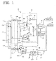
- FIG. 1 shows the circuit construction of a power source unit of an electric motor vehicle provided with the device of the invention for detecting adhesion in the relay due to melting.
- the electric motor vehicle shown in FIG. 1 is provided with a power source unit 12 of high voltage (e.g., of 200 to 300 V in overall voltage) comprising, for example, a plurality of secondary batteries 12a ... 12b, such as nickel hydrogen batteries or lead batteries, which are connected in series.
- a power source unit 12 of high voltage e.g., of 200 to 300 V in overall voltage
- secondary batteries 12a ... 12b such as nickel hydrogen batteries or lead batteries, which are connected in series.
- a pair of main positive line 11a and main negative line 11b Extending respectively from opposite ends of the power source unit 12 are a pair of main positive line 11a and main negative line 11b.
- a load circuit Connected to a pair of output terminals A, B provided at the terminating ends of the pair of these lines 11a, 11b is a load circuit (not shown) including an electric motor and an inverter comprising a switching element such as an IGBT (Insulated Gate Bipolar Transistor).
- IGBT Insulated Gate Bipolar Transistor
- the electric motor vehicle mentioned has a main relay 14 for effecting or interrupting the supply of electric current to the load circuit from the power source unit 12.
- the main relay 14 has a first contact 14a and a second contact 14b which are provided on the respective main positive line 11a and main negative line 11b each at an intermediate portion of the line.
- the main relay 14 has a relay coil 14c for drivingly opening or closing the first contact 14a and the second contact 14b.
- a key switch 24 which can be turned on or off by the user is connected to the relay coil 14c by way of a delay relay 15 and an auxiliary relay 20.
- An auxiliary battery 22 is connected to the key switch 24.
- the electric motor vehicle has a CPU 31.
- the delay relay 15 and the key switch 24 are connected to the CPU 31.
- the electric motor vehicle is provided with the device 10 of the invention for detecting adhesion in the relay by melting.
- the relay adhesion detecting device 10 has a first adhesion detecting positive line 13a branching off from the main positive line 11a between the first contact 14a of the main relay 14 and the output terminal A, and a first adhesion detecting negative line 13b extending from the negative electrode of the secondary battery 12a included among the secondary batteries 12a ... 12b of the power source unit 12 and positioned at the positive-side end thereof.
- a first adhesion detecting circuit 16 Connected to terminating ends of these lines 13a, 13b is a first adhesion detecting circuit 16 for detecting the adhesion, if any, of the first contact 14a of the main relay 14 due to melting as will be described below.
- the relay adhesion detecting device 10 further has a second adhesion detecting positive line 15a extending from the positive electrode of the secondary battery 12b included among the secondary batteries 12a ... 12b of the power source unit 12 and positioned at the negative-side end thereof, and a second adhesion detecting negative line 15b branching off from the main negative line 11b between the second contact 14b of the main relay 14 and the output terminal B.
- a second adhesion detecting circuit 18 Connected to terminating ends of these lines 15a, 15b is a second adhesion detecting circuit 18 for detecting the adhesion, if any, of the second contact 14b of the main relay 14 by melting.
- the second adhesion detecting circuit 18 has the same construction as the first adhesion detecting circuit 16 and is therefore not shown.
- the first and second adhesion detecting circuits 16, 18 are connected to the CPU 31.
- the CPU 31 has connected thereto a nonvolatile memory 40 for storing the result of detecting adhesion in the main relay 14 due to melting.
- Also connected to the CPU 31 are an alarm buzzer 38 and a display 39. In the case where the main relay 14 has its contact adhered by melting, the CPU 31 gives an actuation command to the alarm buzzer 38 and shows an error message on the display 39.
- the first adhesion detecting circuit 16 comprises a first photocoupler 26 and a second photocoupler 30.
- the first photocoupler 26 and the second photocoupler 30 each comprise a light-emitting diode and a phototransistor.
- the phototransistor 26b of the first photocoupler 26 has its collector connected to the first adhesion detecting positive line 13a and its emitter connected to the positive electrode of the light-emitting diode 30a of the second photocoupler 30 via a resistor 28.
- the first adhesion detecting negative line 13b is connected to the negative electrode of the diode 30a.
- the resistor 28 has the function of serving as a current limiting resistor for restricting the current to be supplied to the diode 30a of the second photocoupler 30 to not greater than a predetermined value, and also the function of a protective resistor for preventing the secondary battery 12a of the power source unit 12 from burning by an excess current.
- the magnitude of current to be admitted to the diode 30a of the second photocoupler 30 is limited usually to about 1 mA. For example when a 12-V secondary battery is used as the battery 12a, the resistor 28 is given a value of 12 k ⁇ .
- a closed loop circuit is formed which extends from the positive electrode of the secondary battery 12a of the power source unit 12 to the negative electrode of the battery 12a by way of the first contact 14a of the main relay 14, the phototransistor 26b of the first photocoupler 26, the resistor 28 and the light-emitting diode 30a of the second photocoupler 30. Current then flows through the circuit as indicated by arrows in the drawing.
- the light-emitting diode 26a of the first photocoupler 26 has its positive electrode connected to the CPU 31 via a transistor 32 connected to the power source and a resistor 34, and its negative electrode grounded via a resistor 35.
- the transistor 32 is on/off-controlled by the CPU 31. When the transistor 32 is brought into conduction, current flows through the light-emitting diode 26a of the first photocoupler 26, bringing the phototransistor 26b into conduction. Thus, the first photocoupler 26 is actuated.
- the phototransistor 30b of the second photocoupler 30 has its collector connected to the CPU 31 and its emitter grounded.
- the line from the collector to the CPU 31 is connected to the power source by way of a resistor 36.
- a high signal representing a high voltage value which is a value obtained by subtracting the value of a voltage drop by the resistor 36 from the power source voltage value Vcc is fed to the CPU 31.
- the CPU 31 sets the first photocoupler 26 in conduction, with the first contact 14a opened.
- the closed loop circuit is not formed, with no current flowing through the light-emitting diode 30b of the second photocoupler 30.
- the phototransistor 30b of the second photocoupler 30, i.e., the second photocouplter 30, is held out of conduction, and the high signal is fed to the CPU 31.
- the signal fed from the second photocoupler 30 to CPU 31 is the low signal, the signal indicates thermal adhesion of the first contact 14a of the main relay 14, while if the signal fed from the second photocoupler 30 is the high signal, this indicates that the first contact 14a of the main relay 14 is free of adhesion due to melting.
- the relay adhesion detecting device 10 With the relay adhesion detecting device 10, one of the secondary batteries 12a ... 12b constituting the power source unit 12 is utilized as the power source of each of the first and second adhesion detecting circuits 16, 18, so that the voltage to be applied to the device main body is as low as the voltage value of one secondary battery, e.g., about 12 V. Accordingly, the first and second adhesion detecting circuits 16, 18 comprise elements of low voltage resistance, rendering the device main body compact while ensuring high safety.
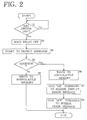
- FIG. 2 shows the control procedure to be performed by the CPU 31 when the key switch 24 closed is turned off after driving.
- the key switch 24 When the key switch 24 is turned off, the supply of power to the power source circuit (not shown) of the CPU 31 is discontinued, whereas power stored in a capacitor provided in the power source circuit is supplied to the CPU 31 to hold the CPU 31 energized only for about 2 seconds.
- the procedure to be described below is executed during this period of 2 seconds.
- step S1 When the key switch 24 is turned off by the user, this change-over is detected in step S1, followed by step S2, in which the first contact 14a and the second contact 14b of the main relay 14 are opened to set the main relay 14 off.
- step S3 the first photocoupler 26 of the first adhesion detecting circuit 16 is brought into conduction, and the first photocoupler (not shown) of the second adhesion detecting circuit 18 is brought into conduction, whereby the CPU starts to check the first contact 14a and the second contact 14b of the main relay 14 for adhesion by melting.
- step S4 Inquiries are made in step S4 as to whether the first contact 14a of the main relay 14 is adhered with reference to the signal fed from the second photocoupler 30 of the first detecting circuit 16 and as to whether the second contact 14b of the main relay 14 is adhered with reference to the signal fed from the second photocoupler (not shown) of the second detecting circuit 18.
- step S4 If the signal fed from the second photocoupler 30 of the first detecting circuit 16 and the signal fed from the second photocoupler of the second detecting circuit 18 are each the high signal, the inquiries are answered in the negative in step S4, followed by step S5 to write to the nonvolatile memory 40 information concerning the result of detecting adhesion and indicating whether the first and second contacts 14a, 14b of the relay 14 are adhered due to melting to terminate the procedure.
- step S4 if one of the signal fed from the second photocoupler 30 of the first detecting circuit 16 and the signal fed from the second photocoupler of the second detecting circuit 18 is the low signal, or each of the signals is the low signal, the inquiries are answered in the affirmative in step S4, followed by step S6 to write to the nonvolatile memory 40 information concerning the result of detection of adhesion of the first and second contacts 14a, 14b of the relay 14.
- step S7 an actuation command is thereafter given to the alarm buzzer 38, and an error message is presented on the display 39 to indicate adhesion in the main relay 14.
- step S8 a deenergization command is given to the alarm buzzer 38, and presentation of the error message is ceased to complete the procedure.
- the first contact 14a and the second contact 14b of the main relay 14 are checked for adhesion due to melting by the above procedure, and when at least one of the contacts is found adhered, an alarm sound is produced from the buzzer 38 with an error message presented on the display 39 only for a short period of less than 2 seconds.
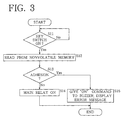
- FIG. 3 shows the control procedure to be performed by the CPU 31 when the key switch 24 which is opened is turned on. Incidentally, the CPU 31 is actuated upon turning on the key switch 24 to execute the procedure to be described below.
- step S11 When the key switch 24 is turned on by the user, this is detected in step S11, which is followed by step S12 to read from the nonvolatile memory 40 the information as to the result of detection of adhesion of the first and second contacts 14a, 14b of the main relay 14.
- step S13 the first contact 14a and the second contact 14b of the main relay 14 are checked for adhesion with reference to the read information.
- step S14 follows to close the first and second contacts 14a, 14b of the main relay 14 to actuate the relay 14 and complete the procedure.
- step S15 to give an actuation command to the alarm buzzer 38 and present on the display 39 an error message indicating adhesion in the relay 14, whereby the procedure is completed.
- the first contact 14a and the second contact 14b of the main relay 14 are checked for adhesion due to melting by the above procedure based on the result of detection of adhesion obtained previously upon turning off the closed key switch 24, and when at least one of the contacts is found adhered, an alarm sound is produced from the buzzer 38 with an error message presented on the display 39.
- the alarm buzzer 38 produces an alarm sound with an error message presented on the display 39 when the key switch 24 as closed is turned off or when the key switch 24 as opened is turned on in the case where at least one of the first and second contacts 14a, 14b of the main relay 14 is adhered by melting.
- This readily indicates the adhesion in the main relay 14 to the person possessing or maintaining the vehicle. If the person thereafter repairs the main relay 14, it is unlikely that an abnormal current will flow through the load circuit to cause damage to the electric motor or the like although this will occur in the conventional electric motor vehicle not equipped with the relay adhesion detecting device.
- the device reliably precludes the power source unit 12 from consuming power uselessly, also ensuring safety of maintenance.
- the main relay 14 is checked for adhesion by melting with reference to the result of detection of adhesion obtained when the key switch 24 is turned off previously. Adhesion is unlikely to occur in the main relay 14 with the key switch 24 in the off state, so that if the main relay 14 is free of thermal adhesion when the key switch 24 is turned off, the main relay 14 remains free of adhesion when the key switch 24 is subsequently turned on. Thus, the check result is highly reliable. Since the main relay 14 is checked for adhesion in this way upon turning on the key switch 24 based on the result of detection of adhesion obtained previously, the power consumption is smaller than when the operation to detect adhesion is performed also when the key switch 24 is turned on.
- first photocoupler 26 of the first adhesion detecting circuit 16 and the first photocoupler of the second adhesion detecting circuit 18 are actuated only when the main relay 14 is to be checked for adhesion due to melting, it is unlikely that current will flow through the closed loop circuit over a long period of time as indicated by arrows in FIG. 1 even in the event of thermal adhesion occurring in the main relay 14. This obviates waste of electric power.
- the present invention is embodied as a relay adhesion detecting device for electric motor vehicles, whereas the device embodying the invention can be used for other known electrically driven vehicles such as bicycles equipped with an electric motor.
- the secondary batteries 12a...12b constituting the power source unit 12 is utilized as the power source for the first and second adhesion detecting circuits 16, 18 according to the foregoing embodiment, a desired number of, and not smaller than two, batteries are usable insofar as they are included among the secondary batteries.
- the nonvolatile memory 40 such that when the key switch 24 is turned on, the main relay 14 is checked for thermal adhesion with reference to the information concerning the result of detection of adhesion and previously written to the memory 40 upon turning off the switch 24, whereas the nonvolatile memory 40 can be dispensed with.
- the first photocoupler 26 of the first adhesion detecting circuit 16 and the photocoupler of the second adhesion detecting circuit 18 are actuated for the detection of adhesion not only when the key switch 24 is turned off but also when the key switch 24 is turned on.
Landscapes
- Engineering & Computer Science (AREA)
- Life Sciences & Earth Sciences (AREA)
- Sustainable Development (AREA)
- Sustainable Energy (AREA)
- Power Engineering (AREA)
- Transportation (AREA)
- Mechanical Engineering (AREA)
- Electric Propulsion And Braking For Vehicles (AREA)
Abstract
A relay adhesion detecting device (10) of the invention
is installed in an electric motor vehicle wherein a relay
(14) is provided between a power source unit (12) comprising
a plurality of secondary batteries and a load circuit
including an electric motor for effecting or interrupting the
supply of current from the power supply unit (12) to the load
circuit. The device (10) comprises one secondary battery
(12a) included among the batteries of the power source unit
(12), the relay (14), an adhesion detecting circuit (16) and
a CPU (31). The CPU (31) detects adhesion in the relay (14)
due to melting by detecting the presence or absence of
current flowing through a closed loop circuit comprising the
secondary battery (12a), the relay (14) and the adhesion
detecting circuit (16).
Description
The present invention relates to a device for detecting
adhesion in relays due to melting for use in electrically
driven vehicles, such as electric motor vehicles, wherein the
relay is interposed between a load circuit including an
electric motor and a plurality of batteries for effecting or
interrupting the supply of current from the batteries to the
load circuit.
Electric motor vehicles are provided with a power source
unit having a high voltage and a great capacity and
comprising a plurality of secondary batteries, such as lead
batteries or nickel hydrogen batteries, which are connected
in series. Electric power is supplied from the power source
unit to a load circuit including an electric motor.
Provided between the power source unit and the load
circuit is a main relay, which is energized or deenergized by
an on/off manipulation of a key switch (ignition switch) of
the electric motor vehicle.
When the key switch is turned off by the user, the main
relay is deenergized to electrically separate the load
circuit from the power source unit, thereby preventing
useless consumption of power and ensuring safety of
maintenance.
The current flowing through the main relay and the load
circuit is as great as up to 400 A if maximum, whereas the
main relay capable of blocking the passage of such a great
current is large-sized and expensive, so that main relays in
used are smaller than 400 A in the value of the current that
can be blocked.
When the main relay is erroneously deenergized in a
state wherein the electric motor vehicle is accelerated, for
example, for starting, with a great current flowing through
the main relay, it is likely that the main relay fails to
completely block the passage of current instantaneously,
permitting occurrence of an arc across the contacts of the
relay and adhesion of the contacts by melting.
Further when the electric motor vehicle is rapidly
accelerated or decelerated during driving, a great charge or
discharge current will flow through the main relay,
consequently causing adhesion of the main relay contacts on
melting.
If the main relay contacts become thermally adhered as
described above, an abnormal current flows through the load
circuit to cause damage to the electric motor or like load.
The main relay is then unable to reliably prevent the power
source unit from wasting electric power and to ensure the
safety of maintenance.
Accordingly, a device has been proposed for detecting
adhesion in main relays of electric motor vehicles due to
melting by checking the presence or absence of current
through a closed loop circuit which includes the main relay
and a plurality of secondary batteries for providing a power
source for the electric motor, etc. (JP-A No. 2000-173428)
However, the secondary batteries provided on the
electric motor vehicle as the power source for the motor, etc.
are all used as the power source for the main relay adhesion
detecting device for the vehicle, so that a high voltage is
applied to the main body of the device. This entails a need
to use elements of great voltage resistance in constructing
the circuit, further giving rise to the problem of making the
device body greater in size and also the problem of low
safety.
An object of the present invention is to provide a
device having a compact main body and ensuring high safety
for detecting adhesion in relays due to melting.
In an electrically driven vehicle wherein a relay is
provided between a load circuit including an electric motor
and a plurality of batteries for effecting or interrupting
the supply of current from the batteries to the load circuit,
the present invention provides a relay adhesion detecting
device for detecting occurrence or absence of adhesion in the
relay due to melting by detecting presence or absence of
current flowing through the relay when the relay is
unenergized using one or more of the batteries as a power
source.
When the contact of the relay is not adhered by melting
with the relay unenergized, no current flows through the
relay and current flowing through the relay is not produced,
but if the relay contact is adhered by melting, the current
from one or more of the plurality of batteries flows through
the relay to pass through the relay.
With the relay adhesion detecting device of the
invention, accordingly, the relay is checked for the adhesion
of its contact due to melting by detecting the presence or
absence of current flowing through the relay.
The relay adhesion detecting device embodying the
invention utilizes as its power source one or more of the
plurality of batteries provided in the electrically driven
vehicle and serving as a power source for the load circuit
including the electric motor, so that the voltage to be
applied to the device main body is lower than in the case of
the conventional relay adhesion detecting device for which
all the batteries installed in the vehicle serve as the power
source. This makes it possible to use elements of small
voltage resistance for the circuit, to compact the device
main body and to achieve improved safety.
Stated more specifically, the device comprises:
When the relay contact is free of adhesion and opened
with the line switching means closed in this specific
construction, no current flows through the current passage
line, whereas if the relay contact is adhered by melting,
current flows through the line as closed.
With the specific construction, therefore, the relay can
be checked for the adhesion of its contact due to melting by
detecting the presence or absence of current flowing through
the current passage line.
If the construction used has no line switching means and
when the relay contact is adhered by melting, current would
flow through the line over a long period of time to result in
a waste of electric power.
With the specific construction described, on the other
hand, the line switching means is closed only when the relay
is checked for adhesion, obviating useless consumption of
power.
Further stated specifically, the line switching means
comprises:
When actuating drive current is supplied to the
photocoupler from the current supply means in this
construction, the photocoupler is actuated with the current
to close the current passage line. If the supply of current
to the photocoupler from the supply means is interrupted, on
the other hand, the photocoupler is brought out of conduction
upon detecting the interruption to open the current passage
line. In this way, the line is closed or opened in
accordance with the supply of current from the supply means
to the photocoupler or interruption of the supply.
Further stated specifically, the adhesion detecting
means comprises:
When the relay is free of adhesion due to melting, no
current flows through the current passage line in this
specific construction as stated above, so that the
photocoupler is then out of conduction. In the event of
adhesion in the relay, current flows through the line to
bring the photocoupler into conduction.
Accordingly, the relay is found free of adhesion when
the photocoupler is off, whereas when in conduction, the
photocoupler indicates adhesion occurring in the relay.
Further stated specifically, the current passage line is
provided with a resistor for limiting the magnitude of
current to be passed through the current passage line to not
greater than a predetermined value.
In this specific construction, the magnitude of the
current to be passed through the current passage line is
limited to not greater than the predetermined value by the
resistor. The above-mentioned one or more of the batteries
can therefore be prevented from becoming thermally damaged
owing to an excess current.
Stated further specifically, the device comprises means
for informing the user of adhesion occurring in the relay due
to melting when the adhesion is detected.
In the event of adhesion occurring in the relay due to
melting in the specific construction, the user is informed of
the occurrence of adhesion in the relay by a known method of
information, for example, by actuating an alarm buzzer or
turning on an alarm lamp. Accordingly, the person possessing
or maintaining the vehicle can be readily informed of the
thermal adhesion in the relay.
As described above, the relay adhesion detecting device
embodying the invention for use in electrically driven
vehicles can be compacted in the device main body and
improved in safety.
With reference to the drawings, a detailed description
will be given of a device embodying the invention for use in
electric motor vehicles for detecting adhesion in a relay due
to melting.
FIG. 1 shows the circuit construction of a power source
unit of an electric motor vehicle provided with the device of
the invention for detecting adhesion in the relay due to
melting.
The electric motor vehicle shown in FIG. 1 is provided
with a power source unit 12 of high voltage (e.g., of 200 to
300 V in overall voltage) comprising, for example, a
plurality of secondary batteries 12a ... 12b, such as nickel
hydrogen batteries or lead batteries, which are connected in
series.
Extending respectively from opposite ends of the power
source unit 12 are a pair of main positive line 11a and main
negative line 11b. Connected to a pair of output terminals A,
B provided at the terminating ends of the pair of these lines
11a, 11b is a load circuit (not shown) including an electric
motor and an inverter comprising a switching element such as
an IGBT (Insulated Gate Bipolar Transistor).
Like conventional electric motor vehicles, the electric
motor vehicle mentioned has a main relay 14 for effecting or
interrupting the supply of electric current to the load
circuit from the power source unit 12.
The main relay 14 has a first contact 14a and a second
contact 14b which are provided on the respective main
positive line 11a and main negative line 11b each at an
intermediate portion of the line. The main relay 14 has a
relay coil 14c for drivingly opening or closing the first
contact 14a and the second contact 14b. A key switch 24
which can be turned on or off by the user is connected to the
relay coil 14c by way of a delay relay 15 and an auxiliary
relay 20. An auxiliary battery 22 is connected to the key
switch 24.
The electric motor vehicle has a CPU 31. The delay
relay 15 and the key switch 24 are connected to the CPU 31.
When the key switch 24 is turned on, current flows from
the auxiliary battery 22 to the relay coil 20b of the
auxiliary relay 20, whereby the relay contact 20a is closed
to actuate the auxiliary relay 20. The closing of the key
switch 24 is detected by the CPU 31, which supplies current
to the relay coil 15b of the delay relay 15, whereby the
relay contact 15a is closed to actuate the relay 15. When
the auxiliary relay 20 and the delay relay 15 are actuated,
current is supplied to the relay coil 14c of the main relay
14, whereby the first contact 14a and the second contact 14b
of the main relay 14 are closed to actuate the main relay 14.
In this way, the main relay 14 is actuated in response to an
action of closing the key switch 24.
The electric motor vehicle is provided with the device
10 of the invention for detecting adhesion in the relay by
melting.
The relay adhesion detecting device 10 has a first
adhesion detecting positive line 13a branching off from the
main positive line 11a between the first contact 14a of the
main relay 14 and the output terminal A, and a first adhesion
detecting negative line 13b extending from the negative
electrode of the secondary battery 12a included among the
secondary batteries 12a ... 12b of the power source unit 12
and positioned at the positive-side end thereof. Connected
to terminating ends of these lines 13a, 13b is a first
adhesion detecting circuit 16 for detecting the adhesion, if
any, of the first contact 14a of the main relay 14 due to
melting as will be described below.
The relay adhesion detecting device 10 further has a
second adhesion detecting positive line 15a extending from
the positive electrode of the secondary battery 12b included
among the secondary batteries 12a ... 12b of the power source
unit 12 and positioned at the negative-side end thereof, and
a second adhesion detecting negative line 15b branching off
from the main negative line 11b between the second contact
14b of the main relay 14 and the output terminal B.
Connected to terminating ends of these lines 15a, 15b is a
second adhesion detecting circuit 18 for detecting the
adhesion, if any, of the second contact 14b of the main relay
14 by melting. Incidentally, the second adhesion detecting
circuit 18 has the same construction as the first adhesion
detecting circuit 16 and is therefore not shown.
The first and second adhesion detecting circuits 16, 18
are connected to the CPU 31. The CPU 31 has connected
thereto a nonvolatile memory 40 for storing the result of
detecting adhesion in the main relay 14 due to melting. Also
connected to the CPU 31 are an alarm buzzer 38 and a display
39. In the case where the main relay 14 has its contact
adhered by melting, the CPU 31 gives an actuation command to
the alarm buzzer 38 and shows an error message on the display
39.
The first adhesion detecting circuit 16 comprises a
first photocoupler 26 and a second photocoupler 30. The
first photocoupler 26 and the second photocoupler 30 each
comprise a light-emitting diode and a phototransistor.
The phototransistor 26b of the first photocoupler 26 has
its collector connected to the first adhesion detecting
positive line 13a and its emitter connected to the positive
electrode of the light-emitting diode 30a of the second
photocoupler 30 via a resistor 28. The first adhesion
detecting negative line 13b is connected to the negative
electrode of the diode 30a. The resistor 28 has the function
of serving as a current limiting resistor for restricting the
current to be supplied to the diode 30a of the second
photocoupler 30 to not greater than a predetermined value,
and also the function of a protective resistor for preventing
the secondary battery 12a of the power source unit 12 from
burning by an excess current. The magnitude of current to be
admitted to the diode 30a of the second photocoupler 30 is
limited usually to about 1 mA. For example when a 12-V
secondary battery is used as the battery 12a, the resistor 28
is given a value of 12 kΩ.
In the case where the main relay 14 has its first
contact 14a adhered by melting and when the phototransistor
26b of the first photocoupler 26 is in conduction, i.e., when
the first photocoupler 26 is in a conducting state, a closed
loop circuit is formed which extends from the positive
electrode of the secondary battery 12a of the power source
unit 12 to the negative electrode of the battery 12a by way
of the first contact 14a of the main relay 14, the
phototransistor 26b of the first photocoupler 26, the
resistor 28 and the light-emitting diode 30a of the second
photocoupler 30. Current then flows through the circuit as
indicated by arrows in the drawing.
The light-emitting diode 26a of the first photocoupler
26 has its positive electrode connected to the CPU 31 via a
transistor 32 connected to the power source and a resistor 34,
and its negative electrode grounded via a resistor 35. The
transistor 32 is on/off-controlled by the CPU 31. When the
transistor 32 is brought into conduction, current flows
through the light-emitting diode 26a of the first
photocoupler 26, bringing the phototransistor 26b into
conduction. Thus, the first photocoupler 26 is actuated.
The phototransistor 30b of the second photocoupler 30
has its collector connected to the CPU 31 and its emitter
grounded. The line from the collector to the CPU 31 is
connected to the power source by way of a resistor 36.
When the phototransistor 30b of the second photocoupler
30 is out of conduction, i.e., when the second photocoupler
30 is out of conduction, a high signal representing a high
voltage value which is a value obtained by subtracting the
value of a voltage drop by the resistor 36 from the power
source voltage value Vcc is fed to the CPU 31.
On the other hand, when the phototransistor 30b of the
second photocoupler 30 is conducting, i.e., when the second
photocoupler 30 is in conduction, a low signal representing a
low voltage value of zero is fed to the CPU 31.
When checking the first contact 14a of the main relay 14
for adhesion due to melting, the CPU 31 sets the first
photocoupler 26 in conduction, with the first contact 14a
opened.
In the event of the adhesion of the first contact 14a of
the main relay 31, current flows through the above-mentioned
closed loop circuit as indicated by arrows in the drawing,
conducting the phototransistor 30b of the second photocoupler
30, i.e., conducting the second photocoupler 30. The low
signal is therefore fed to the CPU 31.
On the other hand, if the first contact 14a of the main
relay 14 is not adhered due to melting, the closed loop
circuit is not formed, with no current flowing through the
light-emitting diode 30b of the second photocoupler 30. The
phototransistor 30b of the second photocoupler 30, i.e., the
second photocouplter 30, is held out of conduction, and the
high signal is fed to the CPU 31.
Accordingly, if the signal fed from the second
photocoupler 30 to CPU 31 is the low signal, the signal
indicates thermal adhesion of the first contact 14a of the
main relay 14, while if the signal fed from the second
photocoupler 30 is the high signal, this indicates that the
first contact 14a of the main relay 14 is free of adhesion
due to melting.
With the relay adhesion detecting device 10, one of the
secondary batteries 12a ... 12b constituting the power source
unit 12 is utilized as the power source of each of the first
and second adhesion detecting circuits 16, 18, so that the
voltage to be applied to the device main body is as low as
the voltage value of one secondary battery, e.g., about 12 V.
Accordingly, the first and second adhesion detecting
circuits 16, 18 comprise elements of low voltage resistance,
rendering the device main body compact while ensuring high
safety.
FIG. 2 shows the control procedure to be performed by
the CPU 31 when the key switch 24 closed is turned off after
driving. When the key switch 24 is turned off, the supply of
power to the power source circuit (not shown) of the CPU 31
is discontinued, whereas power stored in a capacitor provided
in the power source circuit is supplied to the CPU 31 to hold
the CPU 31 energized only for about 2 seconds. The procedure
to be described below is executed during this period of 2
seconds.
When the key switch 24 is turned off by the user, this
change-over is detected in step S1, followed by step S2, in
which the first contact 14a and the second contact 14b of the
main relay 14 are opened to set the main relay 14 off.
Subsequently in step S3, the first photocoupler 26 of
the first adhesion detecting circuit 16 is brought into
conduction, and the first photocoupler (not shown) of the
second adhesion detecting circuit 18 is brought into
conduction, whereby the CPU starts to check the first contact
14a and the second contact 14b of the main relay 14 for
adhesion by melting.
Inquiries are made in step S4 as to whether the first
contact 14a of the main relay 14 is adhered with reference to
the signal fed from the second photocoupler 30 of the first
detecting circuit 16 and as to whether the second contact 14b
of the main relay 14 is adhered with reference to the signal
fed from the second photocoupler (not shown) of the second
detecting circuit 18.
If the signal fed from the second photocoupler 30 of the
first detecting circuit 16 and the signal fed from the second
photocoupler of the second detecting circuit 18 are each the
high signal, the inquiries are answered in the negative in
step S4, followed by step S5 to write to the nonvolatile
memory 40 information concerning the result of detecting
adhesion and indicating whether the first and second contacts
14a, 14b of the relay 14 are adhered due to melting to
terminate the procedure.
On the other hand, if one of the signal fed from the
second photocoupler 30 of the first detecting circuit 16 and
the signal fed from the second photocoupler of the second
detecting circuit 18 is the low signal, or each of the
signals is the low signal, the inquiries are answered in the
affirmative in step S4, followed by step S6 to write to the
nonvolatile memory 40 information concerning the result of
detection of adhesion of the first and second contacts 14a,
14b of the relay 14. In step S7, an actuation command is
thereafter given to the alarm buzzer 38, and an error message
is presented on the display 39 to indicate adhesion in the
main relay 14. Finally in step S8, a deenergization command
is given to the alarm buzzer 38, and presentation of the
error message is ceased to complete the procedure.
Upon turning off the key switch 24 closed, the first
contact 14a and the second contact 14b of the main relay 14
are checked for adhesion due to melting by the above
procedure, and when at least one of the contacts is found
adhered, an alarm sound is produced from the buzzer 38 with
an error message presented on the display 39 only for a short
period of less than 2 seconds.
FIG. 3 shows the control procedure to be performed by
the CPU 31 when the key switch 24 which is opened is turned
on. Incidentally, the CPU 31 is actuated upon turning on the
key switch 24 to execute the procedure to be described below.
When the key switch 24 is turned on by the user, this is
detected in step S11, which is followed by step S12 to read
from the nonvolatile memory 40 the information as to the
result of detection of adhesion of the first and second
contacts 14a, 14b of the main relay 14.
Subsequently in step S13, the first contact 14a and the
second contact 14b of the main relay 14 are checked for
adhesion with reference to the read information.
In the case where neither of the first and second
contacts 14a, 14b of the relay 14 are found adhered, step S14
follows to close the first and second contacts 14a, 14b of
the main relay 14 to actuate the relay 14 and complete the
procedure.
On the other hand, if at least one of the first and
second contacts 14a, 14b of the main relay 14 is found
adhered by melting, the sequence proceeds to step S15 to give
an actuation command to the alarm buzzer 38 and present on
the display 39 an error message indicating adhesion in the
relay 14, whereby the procedure is completed.
Upon turning on the key switch 24 as opened, the first
contact 14a and the second contact 14b of the main relay 14
are checked for adhesion due to melting by the above
procedure based on the result of detection of adhesion
obtained previously upon turning off the closed key switch 24,
and when at least one of the contacts is found adhered, an
alarm sound is produced from the buzzer 38 with an error
message presented on the display 39.
With the electric motor vehicle equipped with the relay
adhesion detecting device 10 of the present embodiment, the
alarm buzzer 38 produces an alarm sound with an error message
presented on the display 39 when the key switch 24 as closed
is turned off or when the key switch 24 as opened is turned
on in the case where at least one of the first and second
contacts 14a, 14b of the main relay 14 is adhered by melting.
This readily indicates the adhesion in the main relay 14 to
the person possessing or maintaining the vehicle. If the
person thereafter repairs the main relay 14, it is unlikely
that an abnormal current will flow through the load circuit
to cause damage to the electric motor or the like although
this will occur in the conventional electric motor vehicle
not equipped with the relay adhesion detecting device.
Furthermore, the device reliably precludes the power source
unit 12 from consuming power uselessly, also ensuring safety
of maintenance.
When the key switch 24 as opened is turned on, the main
relay 14 is checked for adhesion by melting with reference to
the result of detection of adhesion obtained when the key
switch 24 is turned off previously. Adhesion is unlikely to
occur in the main relay 14 with the key switch 24 in the off
state, so that if the main relay 14 is free of thermal
adhesion when the key switch 24 is turned off, the main relay
14 remains free of adhesion when the key switch 24 is
subsequently turned on. Thus, the check result is highly
reliable. Since the main relay 14 is checked for adhesion in
this way upon turning on the key switch 24 based on the
result of detection of adhesion obtained previously, the
power consumption is smaller than when the operation to
detect adhesion is performed also when the key switch 24 is
turned on.
Further because the first photocoupler 26 of the first
adhesion detecting circuit 16 and the first photocoupler of
the second adhesion detecting circuit 18 are actuated only
when the main relay 14 is to be checked for adhesion due to
melting, it is unlikely that current will flow through the
closed loop circuit over a long period of time as indicated
by arrows in FIG. 1 even in the event of thermal adhesion
occurring in the main relay 14. This obviates waste of
electric power.
According to the foregoing embodiment, the present
invention is embodied as a relay adhesion detecting device
for electric motor vehicles, whereas the device embodying the
invention can be used for other known electrically driven
vehicles such as bicycles equipped with an electric motor.
Although one of the secondary batteries 12a...12b
constituting the power source unit 12 is utilized as the
power source for the first and second adhesion detecting
circuits 16, 18 according to the foregoing embodiment, a
desired number of, and not smaller than two, batteries are
usable insofar as they are included among the secondary
batteries.
Further the foregoing embodiment has incorporated
therein the nonvolatile memory 40, such that when the key
switch 24 is turned on, the main relay 14 is checked for
thermal adhesion with reference to the information concerning
the result of detection of adhesion and previously written to
the memory 40 upon turning off the switch 24, whereas the
nonvolatile memory 40 can be dispensed with. In this case,
the first photocoupler 26 of the first adhesion detecting
circuit 16 and the photocoupler of the second adhesion
detecting circuit 18 are actuated for the detection of
adhesion not only when the key switch 24 is turned off but
also when the key switch 24 is turned on.
Claims (6)
- In an electrically driven vehicle wherein a relay is provided between a load circuit including an electric motor and a plurality of batteries for effecting or interrupting the supply of current from the batteries to the load circuit, a relay adhesion detecting device for detecting occurrence or absence of adhesion in the relay due to melting by detecting presence or absence of current flowing through the relay when the relay is unenergized using one or more of the batteries as a power source.
- A relay adhesion detecting device according to claim 1 which comprises:a current passage line for passing current through the relay from one or more of the batteries serving as the power source,line switching means provided on the current passage line for opening or closing the current passage line, andadhesion detecting means provided on the current passage line for detecting occurrence or absence of adhesion in the relay due to melting by detecting presence or absence of current flowing through the current passage line.
- A relay adhesion detecting device according to claim 2 wherein the line switching means comprises:a photocoupler provided on the current passage line and operable by being supplied with current, andcurrent supply means for supplying actuating drive current to the photocoupler.
- A relay adhesion detecting device according to claim 2 or 3 wherein the adhesion detecting means comprises:a photocoupler provided on the current passage line and operable by being supplied with current, andmeans for checking the relay for adhesion due to melting based on the on/off state of the photocoupler.
- A relay adhesion detecting device according to any one of claims 2 to 4 wherein the current passage line is provided with a resistor for limiting the magnitude of current to be passed through the current passage line to not greater than a predetermined value.
- A relay adhesion detecting device according to any one of claims 1 to 5 which comprises means for informing the user of adhesion occurring in the relay due to melting when the adhesion is detected.
Applications Claiming Priority (3)
| Application Number | Priority Date | Filing Date | Title |
|---|---|---|---|
| JP2000041554 | 2000-02-18 | ||
| JP2000041554 | 2000-02-18 | ||
| PCT/JP2001/001185 WO2001060652A1 (en) | 2000-02-18 | 2001-02-19 | Relay fusion detector for electrically driven vehicles |
Publications (2)
| Publication Number | Publication Date |
|---|---|
| EP1256480A1 true EP1256480A1 (en) | 2002-11-13 |
| EP1256480A4 EP1256480A4 (en) | 2011-06-22 |
Family
ID=18564774
Family Applications (1)
| Application Number | Title | Priority Date | Filing Date |
|---|---|---|---|
| EP01904554A Withdrawn EP1256480A4 (en) | 2000-02-18 | 2001-02-19 | Relay fusion detector for electrically driven vehicles |
Country Status (6)
| Country | Link |
|---|---|
| US (1) | US6683778B2 (en) |
| EP (1) | EP1256480A4 (en) |
| JP (1) | JP3789819B2 (en) |
| KR (1) | KR100432285B1 (en) |
| CN (1) | CN1217809C (en) |
| WO (1) | WO2001060652A1 (en) |
Cited By (6)
| Publication number | Priority date | Publication date | Assignee | Title |
|---|---|---|---|---|
| EP2166365A1 (en) * | 2008-09-19 | 2010-03-24 | Bombardier Transportation GmbH | Distributed safety monitoring system provided with a safety loop and method of testing such a system |
| WO2011098282A1 (en) * | 2010-02-12 | 2011-08-18 | Festo Ag & Co. Kg | Device for electric circuit monitoring, circuit arrangement for supplying a load and method for operating a circuit arrangement |
| FR2972687A1 (en) * | 2011-03-18 | 2012-09-21 | Peugeot Citroen Automobiles Sa | Traction storage system for e.g. electric vehicle, has analyzing device analyzing operating condition of contactors and including dipoles, and control device controlling closing process of contactors and detecting current flow in dipoles |
| WO2013013763A1 (en) * | 2011-07-23 | 2013-01-31 | Volkswagen Aktiengesellschaft | Method and test system for testing a contactor arrangement for a vehicle |
| WO2015011531A1 (en) * | 2013-07-23 | 2015-01-29 | Toyota Jidosha Kabushiki Kaisha | Electrical storage system, battery system, and failure determination method |
| DE102015224658A1 (en) * | 2015-12-09 | 2017-06-14 | Lisa Dräxlmaier GmbH | Electromechanical circuit breaker |
Families Citing this family (45)
| Publication number | Priority date | Publication date | Assignee | Title |
|---|---|---|---|---|
| JP2003139810A (en) * | 2001-10-31 | 2003-05-14 | Toyoda Mach Works Ltd | Relay failure detection device |
| JP3945630B2 (en) * | 2002-01-10 | 2007-07-18 | パナソニック・イーブイ・エナジー株式会社 | Relay contact welding inspection method for battery power supply |
| CN100454466C (en) * | 2003-03-31 | 2009-01-21 | 日本电气株式会社 | Method and device for detecting welding of relay contacts |
| JP4416585B2 (en) * | 2004-07-06 | 2010-02-17 | 三洋電機株式会社 | Power supply for vehicle |
| US7514815B2 (en) * | 2004-09-28 | 2009-04-07 | American Power Conversion Corporation | System and method for allocating power to loads |
| JP2007026741A (en) * | 2005-07-13 | 2007-02-01 | Jtekt Corp | Relay contact welding detection device |
| US7446437B2 (en) | 2005-07-22 | 2008-11-04 | American Power Conversion Corporation | Apparatus and method for preventing an electrical backfeed |
| JP4749190B2 (en) | 2006-03-24 | 2011-08-17 | 三洋電機株式会社 | Welding detection method for discriminating welding of power supply device for vehicle and contactor of this power supply device |
| JP4788461B2 (en) * | 2006-04-24 | 2011-10-05 | トヨタ自動車株式会社 | Power supply control device and relay abnormality detection method |
| KR100918564B1 (en) | 2006-04-26 | 2009-09-21 | 주식회사 엘지화학 | How to detect relay status of battery device |
| JP2008301612A (en) * | 2007-05-31 | 2008-12-11 | Sanyo Electric Co Ltd | Power supply device for vehicle, and contactor welding detecting method for the same |
| KR100916430B1 (en) * | 2007-12-12 | 2009-09-07 | 현대자동차주식회사 | How to control high voltage relay in hybrid vehicle |
| DE102008011495B4 (en) * | 2008-02-19 | 2011-09-22 | E.G.O. Control Systems Gmbh | Control device for a household appliance, household appliance and associated method |
| EP2166333B1 (en) * | 2008-09-19 | 2012-01-25 | Bombardier Transportation GmbH | Testable vibration monitoring device and method |
| EP2165912B1 (en) * | 2008-09-19 | 2012-04-25 | Bombardier Transportation GmbH | Instability monitoring device and system, in particular for a rail vehicle |
| US8200370B2 (en) * | 2008-12-04 | 2012-06-12 | American Power Conversion Corporation | Energy reduction |
| US20100145884A1 (en) * | 2008-12-04 | 2010-06-10 | American Power Conversion Corporation | Energy savings aggregation |
| JP2011054762A (en) * | 2009-09-02 | 2011-03-17 | Tokyo Electron Ltd | Device and method for monitoring static eliminator, and monitoring program for static eliminator |
| CN103201927B (en) * | 2010-11-05 | 2016-02-10 | 丰田自动车株式会社 | The power supply system of the vehicle and the vehicle equipped with the power supply system |
| JP5461478B2 (en) | 2011-06-15 | 2014-04-02 | 富士重工業株式会社 | Charging system and electric vehicle |
| JP2013206643A (en) * | 2012-03-28 | 2013-10-07 | Hitachi Ltd | Relay fusion detector of battery system, and battery system using the same |
| US9792552B2 (en) | 2012-06-29 | 2017-10-17 | Schneider Electric USA, Inc. | Prediction of available generator running time |
| JP5370553B1 (en) * | 2012-08-31 | 2013-12-18 | オムロン株式会社 | Electromagnetic relay welding detection device and electromagnetic relay welding detection method |
| JP6308486B2 (en) * | 2012-09-13 | 2018-04-11 | パナソニックIpマネジメント株式会社 | Relay welding detector |
| JP6092638B2 (en) * | 2013-01-23 | 2017-03-08 | 矢崎総業株式会社 | Vehicle power supply control device |
| JP2016012411A (en) * | 2014-06-27 | 2016-01-21 | 矢崎エナジーシステム株式会社 | Charge control device and relay fixture detection method thereof |
| KR101821008B1 (en) | 2014-09-15 | 2018-03-08 | 엘에스산전 주식회사 | Electic automobile recharge apparatus |
| JP6145446B2 (en) * | 2014-12-24 | 2017-06-14 | 矢崎総業株式会社 | Relay drive circuit |
| CN104793135B (en) * | 2015-05-06 | 2018-05-22 | 科力远混合动力技术有限公司 | A kind of hybrid vehicle relay status detection circuit and method |
| JP2016225132A (en) * | 2015-05-29 | 2016-12-28 | 矢崎総業株式会社 | Power supply control device |
| KR101664745B1 (en) * | 2015-09-25 | 2016-10-24 | 현대자동차주식회사 | Method for detecting fusion of relay of battery |
| KR101673822B1 (en) * | 2015-11-18 | 2016-11-07 | 현대자동차주식회사 | Apparatus and method for detecting relay welding in green car |
| US10106042B2 (en) | 2015-11-24 | 2018-10-23 | GM Global Technology Operations LLC | Methods of operating contactors in high voltage circuits of vehicles |
| US10017071B2 (en) * | 2016-10-13 | 2018-07-10 | GM Global Technology Operations LLC | Method and system for diagnosing contactor health in a high-voltage electrical system |
| CN106449274B (en) * | 2016-10-31 | 2018-08-21 | 国网山东省电力公司莱芜供电公司 | A kind of relay output device with self diagnosis warning function and its diagnostic alarms method |
| CN109557403A (en) * | 2017-12-29 | 2019-04-02 | 蜂巢能源科技有限公司 | The contacts of contactor adhesion detection device and method of vehicle |
| US12066654B2 (en) * | 2018-11-19 | 2024-08-20 | Rai Strategic Holdings, Inc. | Charging control for an aerosol delivery device |
| CN109596940A (en) * | 2018-12-29 | 2019-04-09 | 蜂巢能源科技有限公司 | The detection device of power battery charging contacts of contactor adhesion, vehicle |
| CN112578273A (en) * | 2019-09-30 | 2021-03-30 | 江苏万帮德和新能源科技股份有限公司 | Adhesion detection device and method for alternating current circuit relay and alternating current charging pile |
| JP7095016B2 (en) | 2020-04-17 | 2022-07-04 | 富士電機株式会社 | Power converter |
| CN111679183B (en) * | 2020-07-01 | 2022-08-16 | 中国第一汽车股份有限公司 | Relay adhesion detection circuit and method, vehicle and storage medium |
| CN113246734B (en) * | 2021-06-09 | 2024-10-29 | 深圳市誉娇诚科技有限公司 | A coil drive circuit for a high voltage relay on an electric vehicle |
| KR20230082970A (en) * | 2021-12-02 | 2023-06-09 | 주식회사 엘지에너지솔루션 | Relay welding dignosis circuit and relay welding dignosis method |
| CN115015744A (en) * | 2022-06-02 | 2022-09-06 | 深圳巴斯巴科技发展有限公司 | AC charging pile relay adhesion detection circuit |
| CN115684917B (en) * | 2022-11-23 | 2026-03-31 | 上海希形科技有限公司 | A relay normally open contact adhesion detection circuit for SVG |
Family Cites Families (9)
| Publication number | Priority date | Publication date | Assignee | Title |
|---|---|---|---|---|
| JPH06233401A (en) * | 1993-02-02 | 1994-08-19 | Toyota Motor Corp | Inverter input relay device for electric vehicle |
| US5883816A (en) * | 1995-10-13 | 1999-03-16 | Belanger, Inc. | Interface circuit for processor controlled system and vehicle laundry system utilizing such interface circuit |
| JPH09149508A (en) * | 1995-11-20 | 1997-06-06 | Isuzu Motors Ltd | Electric vehicle power supply |
| GB9604431D0 (en) * | 1996-03-01 | 1996-05-01 | Lucas Ind Plc | Circuit for testing an electrical actuator drive stage |
| JP3769843B2 (en) * | 1996-11-07 | 2006-04-26 | 日産自動車株式会社 | High-voltage relay diagnostic device for electric vehicles |
| BR9811960A (en) * | 1997-08-22 | 2000-08-15 | Bosch Gmbh Robert | Process for recognizing connection errors of a first relay |
| DE19753852A1 (en) * | 1997-12-04 | 1999-06-17 | Siemens Ag | Electromagnetic relay |
| JP2000134707A (en) * | 1998-10-26 | 2000-05-12 | Toyota Motor Corp | Power control device |
| JP2000173428A (en) * | 1998-12-01 | 2000-06-23 | Sanyo Electric Co Ltd | Welding detector for main relays of electric vehicles |
-
2001
- 2001-02-19 JP JP2001559722A patent/JP3789819B2/en not_active Expired - Fee Related
- 2001-02-19 KR KR10-2001-7012516A patent/KR100432285B1/en not_active Expired - Fee Related
- 2001-02-19 EP EP01904554A patent/EP1256480A4/en not_active Withdrawn
- 2001-02-19 WO PCT/JP2001/001185 patent/WO2001060652A1/en not_active Ceased
- 2001-02-19 CN CN01800329XA patent/CN1217809C/en not_active Expired - Fee Related
- 2001-02-19 US US09/926,101 patent/US6683778B2/en not_active Expired - Lifetime
Cited By (11)
| Publication number | Priority date | Publication date | Assignee | Title |
|---|---|---|---|---|
| EP2166365A1 (en) * | 2008-09-19 | 2010-03-24 | Bombardier Transportation GmbH | Distributed safety monitoring system provided with a safety loop and method of testing such a system |
| WO2010031570A1 (en) * | 2008-09-19 | 2010-03-25 | Bombardier Transportation Gmbh | Distributed safety monitoring system provided with a safety loop and method of testing such a system |
| RU2503966C2 (en) * | 2008-09-19 | 2014-01-10 | Бомбардир Транспортацион Гмбх | Distributed safety monitoring with safety circuit and method for testing of such system |
| WO2011098282A1 (en) * | 2010-02-12 | 2011-08-18 | Festo Ag & Co. Kg | Device for electric circuit monitoring, circuit arrangement for supplying a load and method for operating a circuit arrangement |
| CN102822930A (en) * | 2010-02-12 | 2012-12-12 | 费斯托股份有限两合公司 | Device for monitoring an electrical circuit, circuit arrangement for supplying a load and method for operating the circuit arrangement |
| CN102822930B (en) * | 2010-02-12 | 2015-04-08 | 费斯托股份有限两合公司 | Device for monitoring an electrical circuit, circuit arrangement for supplying a load and method for operating the circuit arrangement |
| FR2972687A1 (en) * | 2011-03-18 | 2012-09-21 | Peugeot Citroen Automobiles Sa | Traction storage system for e.g. electric vehicle, has analyzing device analyzing operating condition of contactors and including dipoles, and control device controlling closing process of contactors and detecting current flow in dipoles |
| WO2013013763A1 (en) * | 2011-07-23 | 2013-01-31 | Volkswagen Aktiengesellschaft | Method and test system for testing a contactor arrangement for a vehicle |
| WO2015011531A1 (en) * | 2013-07-23 | 2015-01-29 | Toyota Jidosha Kabushiki Kaisha | Electrical storage system, battery system, and failure determination method |
| DE102015224658A1 (en) * | 2015-12-09 | 2017-06-14 | Lisa Dräxlmaier GmbH | Electromechanical circuit breaker |
| DE102015224658B4 (en) | 2015-12-09 | 2018-03-29 | Lisa Dräxlmaier GmbH | Electromechanical circuit breaker |
Also Published As
| Publication number | Publication date |
|---|---|
| KR100432285B1 (en) | 2004-05-22 |
| US6683778B2 (en) | 2004-01-27 |
| EP1256480A4 (en) | 2011-06-22 |
| JP3789819B2 (en) | 2006-06-28 |
| US20030007305A1 (en) | 2003-01-09 |
| CN1217809C (en) | 2005-09-07 |
| KR20020085776A (en) | 2002-11-16 |
| WO2001060652A1 (en) | 2001-08-23 |
| CN1362920A (en) | 2002-08-07 |
Similar Documents
| Publication | Publication Date | Title |
|---|---|---|
| US6683778B2 (en) | Device for use in electric vehicles for detecting adhesion in relay due to melting | |
| JPWO2001060652A1 (en) | Relay welding detection device for electric vehicles | |
| KR100750463B1 (en) | Relay contact welding detection method and apparatus | |
| US7557460B2 (en) | Electric power source for motor vehicle | |
| JP2812066B2 (en) | Power supply voltage switching device for vehicles | |
| JP2000173428A (en) | Welding detector for main relays of electric vehicles | |
| JP7119401B2 (en) | FAILURE DIAGNOSIS DEVICE, POWER STORAGE DEVICE, FAILURE DIAGNOSIS METHOD | |
| US11588188B2 (en) | Battery unit | |
| CN112255539B (en) | A adhesion fault detection circuit for high-side contactor | |
| JPH09284902A (en) | Short circuit detection circuit for electric vehicles | |
| JP2017079496A (en) | Contactor failure determination device and contactor failure determination method | |
| US6333568B1 (en) | Switching arrangement and process for switching off an electric energy source of a vehicle | |
| US4025836A (en) | Protective system against commutation failure in a chopper circuit | |
| JP2009248885A (en) | Auxiliary power supply system of electric power steering device | |
| JPH1082820A (en) | Circuit breaker coil disconnection monitoring device | |
| JPH09293440A (en) | Control method of relay | |
| JP3662431B2 (en) | Control circuit | |
| JP2005184910A (en) | Failure determination device for electric circuit for vehicle | |
| JP7744109B2 (en) | Power Supply Control Device | |
| CN223199877U (en) | Multi-circuit pre-charging device and vehicle | |
| JPH1159293A (en) | Vehicle power supply device and vehicle power supply system | |
| JP2006196251A (en) | Interlock circuit | |
| CN112054790B (en) | A delay switching device, power supply system and control method of a delay switching device | |
| JP2006278003A (en) | Relay system | |
| JPH05319184A (en) | Power supply voltage switching device for vehicles |
Legal Events
| Date | Code | Title | Description |
|---|---|---|---|
| PUAI | Public reference made under article 153(3) epc to a published international application that has entered the european phase |
Free format text: ORIGINAL CODE: 0009012 |
|
| 17P | Request for examination filed |
Effective date: 20010918 |
|
| AK | Designated contracting states |
Kind code of ref document: A1 Designated state(s): AT BE CH CY DE DK ES FI FR GB GR IE IT LI LU MC NL PT SE TR |
|
| RBV | Designated contracting states (corrected) |
Designated state(s): DE FR GB IT SE |
|
| A4 | Supplementary search report drawn up and despatched |
Effective date: 20110524 |
|
| STAA | Information on the status of an ep patent application or granted ep patent |
Free format text: STATUS: THE APPLICATION IS DEEMED TO BE WITHDRAWN |
|
| 18D | Application deemed to be withdrawn |
Effective date: 20130903 |