EP1256456A2 - Sheet material feeding apparatus and recording apparatus - Google Patents
Sheet material feeding apparatus and recording apparatus Download PDFInfo
- Publication number
- EP1256456A2 EP1256456A2 EP02010444A EP02010444A EP1256456A2 EP 1256456 A2 EP1256456 A2 EP 1256456A2 EP 02010444 A EP02010444 A EP 02010444A EP 02010444 A EP02010444 A EP 02010444A EP 1256456 A2 EP1256456 A2 EP 1256456A2
- Authority
- EP
- European Patent Office
- Prior art keywords
- sheet material
- feeding roller
- roller
- feeding
- separation roller
- Prior art date
- Legal status (The legal status is an assumption and is not a legal conclusion. Google has not performed a legal analysis and makes no representation as to the accuracy of the status listed.)
- Granted
Links
Images



Classifications
-
- B—PERFORMING OPERATIONS; TRANSPORTING
- B41—PRINTING; LINING MACHINES; TYPEWRITERS; STAMPS
- B41J—TYPEWRITERS; SELECTIVE PRINTING MECHANISMS, i.e. MECHANISMS PRINTING OTHERWISE THAN FROM A FORME; CORRECTION OF TYPOGRAPHICAL ERRORS
- B41J13/00—Devices or arrangements of selective printing mechanisms, e.g. ink-jet printers or thermal printers, specially adapted for supporting or handling copy material in short lengths, e.g. sheets
- B41J13/10—Sheet holders, retainers, movable guides, or stationary guides
- B41J13/103—Sheet holders, retainers, movable guides, or stationary guides for the sheet feeding section
Definitions
- the present invention relates to a sheet material feeding apparatus which takes a sheet material one by one from a sheaf of the plural stacked sheet materials and then transports the taken sheet materials, and more particularly, to a sheet material feeding apparatus which is provided with a mechanism for preventing so-called multifeeding (or overlap feeding) that plural sheet materials are fed together when a one-time feeding operation is performed.
- an automatic sheet feeding apparatus which is provided with a multifeeding prevention mechanism of retard system
- a system in which an operation to urge a pressure plate for causing a stacked sheet to come into pressure-contact with a paper (or sheet) feeding roller into the paper feeding roller and to move (or shift) the pressure plate to release it from the paper feeding roller is driven by rotation of the shaft of the paper feeding roller with use of a cam on this shaft.
- a contact speed between the sheet on the pressure plate and the paper feeding roller is restrained by driving the paper feeding roller at low speed, so as to reduce a crush sound made when the sheet comes into contact with the paper feeding roller.
- a planet gear clutch or the like might be used to transmit the driving force to other units in the middle of its transmission system.
- the cam on the shaft of the paper feeding roller is pressed by a cam of the pressure plate, and a gear engaging portion of a planet gear is thus released, whereby an antecedent rotation phenomenon of the paper feeding roller occurs.
- the contact speed between the sheet and the paper feeding roller can not be restrained, whereby the crush sound can not be reduced resultingly.
- An object of the present invention is to provide a sheet material feeding apparatus and a recording apparatus which are provided respectively with simple-structure multifeeding prevention mechanisms for preventing the apparatuses from becoming large in size and bringing an increase in cost.
- Another object of the present invention is to provide a sheet material feeding apparatus comprising: a sheet material stacking means for stacking sheet materials; a feeding roller for feeding the sheet materials stacked on the sheet material stacking means; a separation roller, rotating according to the feeding roller, for separating the sheet material; a separation roller holder for rotatably holding the separation roller, the separation roller holder rotating to cause the separation roller to move to a position being in contact with the feeding roller and to a position being released from the feeding roller; and an urging means for urging the sheet material stacking means to the feeding roller to cause the sheet materials stacked on the sheet material stacking means to come into contact with the feeding roller, wherein, after the separation roller came into contact with the feeding roller, it causes the sheet materials stacked on the sheet material stacking means to come into contact with the feeding roller.
- Fig. 1 is a perspective view schematically showing an entire structure of a sheet material feeding apparatus (also called an ASF (automatic sheet feeder)) according to one embodiment of the present invention.
- ASF automatic sheet feeder
- a feeding shaft 10 is rotatably fit on an ASF base 15 which functions as a frame (framework) of the apparatus, a feeding roller 11 which feeds and transports sheet materials such as paper and the like is fit on a part of the feeding shaft 10, and the feeding roller 11 is rotatably supported by the feeding shaft 10 on the ASF base 15. Further, a feeding roller 18 which is to prevent the feeding roller 11 from being in contact with the sheet material when a rotation angle of the feeding roller 11 is within a predetermined range is rotatably fit on a portion of the feeding shaft 10 adjacent to the feeding roller 11.
- a separation roller 12 which is added with a torque limiter and functions as a friction separation means concerning an operation to separate the sheet material on the sheet material feeding apparatus is fit on the ASF base 15 through a holder 27 which rotatably supports the separation roller 12, as later described with reference to Fig. 2. Then, the separation roller 12 is pressed against the feeding roller 11 by springs fit on the holder 27 and the ASF base 15. In the embodiment, the separation roller 12 is rotatably supported so that the roller 12 is urged to the side of the feeding roller 11 to come into pressure-contact with the sheet material so as to nip this sheet material between the rollers 11 and 12 and is also rotated according to the movement of the sheet material nipped between the rollers 11 and 12.
- Plural turn-back levers 13 which function as a turn-back member concerning with prevention of so-called multifeeding that the plural sheet materials from the sheet material feeding apparatus are fed and transported as they overlap each other are swingably fit on the ASF base 15, and each turn-back lever 13 is urged to one direction by a spring.
- a control cam 14 which is to drive the turn-back levers 13 is disposed at one end portion of the ASF base 15. The control cam 14 is fit on a member which drives the respective turn-back levers 13, and rotatably supported together with this member.
- the ASF base 15 includes an inclined portion which is inclined in a use state, and a pressure plate 16 which functions as a pressing member for pressing a sheaf of the sheet materials against the feeding roller 11 is fit on the upper surface of the inclined portion.
- the pressure plate 16 is urged to the side of the feeding roller 11 by a not-shown pressure plate spring set between the pressure plate 16 and the ASF base 15, whereby the sheaf of the sheet materials stacked on the pressure plate 16 is pressed against the side of the feeding roller 11 by the pressure plate 16 and the pressure plate spring.
- a side guide 17 is slidably fit on the pressure plate 16 in a direction C perpendicular to a sheet material transportation direction A of the feeding roller 11 as shown in Fig. 1. The side guide 17 is to position the sheet materials in the direction C on the pressure plate 16.
- the sheet material feeding apparatus of the embodiment is designed on the premise that this apparatus is installed in another apparatus such as a recording apparatus or the like and thus used as one body of such another apparatus, whereby any driving source is not provided in the sheet material feeding apparatus itself. Therefore, the sheet material feeding apparatus of the embodiment is structured as a driven apparatus which is driven by receiving driving force transmitted from, e.g., the side of the body of the recording apparatus.
- the sheet material feeding apparatus is installed in the recording apparatus will be explained by way of example.
- the apparatus in which the sheet material feeding apparatus is to be installed is not limited to the recording apparatus.
- the sheet material feeding apparatus of the embodiment is roughly composed of a sheet material stacking unit, a feeding/separation unit and a multifeeding prevention unit. First, a structure of the sheet material stacking unit will be explained.
- the sheet material stacking unit of the sheet material feeding apparatus is composed of the side guide 17 and the pressure plate 16.
- a sheet material transportation basis portion 15a which is provided to project from a part of the ASF base 15 is set as the basis on the side of the sheet material
- the side guide 17 is set to regulate the side edges of the sheet materials on the side opposite to the sheet material transportation basis portion 15a.
- the pressure plate 16 stops at a predetermined position in a direction apart from the feeding roller 11, and in this state an interspace sufficient to stack the plural sheet materials is secured between the feeding roller 11 and the pressure plate 16.
- the sheet material feeding apparatus of the embodiment is designed to be adapted to a desired sheet material width within a range of a predetermined width.
- the side guide 17 is slid in the direction C of Fig. 1 to be adapted to the sheet material width after the plural sheet materials are stacked at the interspace between the feeding roller 11 and the pressure plate 16 along the sheet material transportation basis portion 15a, the movement of the sheaf of the stacked sheet materials in the direction perpendicular to the sheet material transportation direction is regulated, whereby steady transportation can be performed.
- the side guide 17 is slidably fit on the pressure plate 16, the side guide 17 itself is structured to be fixable by engaging with a latch groove made on the pressure plate 16 so as not to move needlessly. Therefore, when the side guide 17 is moved, the engagement between the side guide 17 and the latch groove on the pressure plate 16 is released by operating a lever unit provided on the side guide 17.
- the sheet materials set on the sheet material stacking unit are urged downward by gravity, and the lower edge of the sheet material bumps to a sheet material leading edge basis portion 15b provided fixedly on the ASF base 15.
- the sheet material leading edge basis portion 15b has a rib shape.
- Fig. 2 is the schematic side view showing the sheet material feeding apparatus being viewed from a direction B shown in Fig. 1.
- an input gear 20, a double gear 21, a feeding shaft gear 22, a control gear 23 and the control cam 14 are disposed on the side of the ASF base 15.
- the input gear 20 is engaged with a gear on the side of the body of the recording apparatus when the sheet material feeding apparatus is installed in the body of the recording apparatus, whereby the input gear 20 receives the driving force from the gear on the side of the body of the recording apparatus.
- the double gear 21 is composed of two gear units which are coaxially arranged and respectively have different diameters, and the gear unit having the smaller diameter is engaged with the input gear 20, whereby the driving force transmitted to the input gear 20 is further transmitted to a next-stage gear through the double gear 21.
- the feeding shaft gear 22 is fixed to one end of the feeding shaft 10 and also engaged with the gear unit having the larger diameter of the double gear 21, whereby the driving force transmitted from the double gear 21 is further transmitted from the feeding shaft gear 22 to the feeding shaft 10 and a next-stage gear.
- the control gear 23 is engaged with the feeding shaft gear 22, whereby the driving of the turn-back levers 13 and the separation roller 12 is controlled on the basis of the driving force transmitted from the feeding shaft gear 22.
- a cam 23a which is engaged with the control cam 14 to control a driving operation of the control cam 14 is formed on one side of the control gear 23.
- One end of an urging spring 25 is fit on an engaging portion formed on the side of the control cam 14, while the other end thereof is fit on an engaging portion formed on the ASF base 15.
- the urging spring 25 is to urge the control cam 14 into its one rotation direction so as to regulate a relative rotation angle of the control cam 14 with respect to the turn-back lever 13 to a predetermined angle in accordance with a rotative operation of the cam 23a.
- pressure springs 26 are fit on the holder 27 rotatably supporting the separation roller 12 and on the ASF base 15 respectively, whereby the separation roller 12 is pressed toward the feeding roller 11 by the pressure spring 26.
- the driving force which is transmitted from the gear provided on the body of the recording apparatus causes the input gear 20 to rotate in the direction B shown in Fig. 2. Then, the driving force transmitted to the input gear 20 is further transmitted to the feeding shaft gear 22 through the double gear 21 which rotates at rotation speed decelerated lower than that of the input gear 20, whereby the feeding shaft gear 22 is rotated in the direction A of Fig. 2.
- the driving force transmitted to the feeding shaft gear 22 is further transmitted to the control gear 23.
- the feeding shaft gear 22 and the control gear 23 are linked together at a deceleration ratio of 1:1, these gears rotate always with a synchronized angle phase.
- a cam follower portion 14b which projects from this side is formed on the side of the control cam 14. Since the cam follower portion 14b which is urged by the urging spring 25 always follows the cam 23a, the control cam 14 is driven and controlled in synchronism with the feeding shaft 10. Further, a control cam 28 later described in Fig. 5 is driven by a not-shown cam provided on the side opposite to the side of the cam 23a of the control gear 23, whereby the position of the separation roller 12 is driven and controlled in synchronism with the feeding shaft 10 in accordance with the operation of the control cam 28. Therefore, a control means which controls an operation to move the separation roller 12 is structured on the basis of the cam provided on the side opposite to the side of the cam 23a of the control gear 23 and the control cam 28.
- the separation roller 12 is rotatably held by the holder 27, the holder 27 itself is rotatably supported based on a rotation center, and, as described above, the separation roller 12 is urged toward the feeding roller 11 by the action of the pressure spring 26. Further, the driving of the separation roller 12 is controlled by the above control cam 28 to release the urging to the control cam 14 by the urging spring 25 at later-described necessary timing and thus release the separation roller 12 from the feeding roller 11.
- the above-explained structure corresponds to the driving mechanism portion, and next a structure of the feeding/separation unit will be explained.
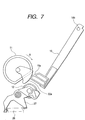
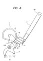
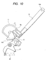
- Figs. 7 to 10 are side views respectively showing the operation of the sheet material feeding apparatus shown in Fig. 1.
- Figs. 7 to 10 only the peripheral portions of the pressure plate 16, the feeding roller 11 and the separation roller 12 are shown to explain the relation of the pressure plate 16, the feeding roller 11 and the separation roller 12.
- the pressure plate 16 includes a rotation spindle 16b at its upper end in a use state, whereby the pressure plate 16 rotatably moves on the basis of the rotation spindle 16b.
- the operation of the pressure plate 16 is regulated by springs and cams. That is, the pressure plate 16 is pressed by a not-shown pressure plate spring so as to be rotated, whereby the pressure plate 16 is urged toward the feeding roller 11.
- a cam 16a is provided at the lower end of the pressure plate 16.
- a cam 22a is provided on the surface of the feeding roller 11 of the feeding shaft gear 22 shown in Fig. 2, and the cam 22a is shown in Figs. 7 to 10 respectively.
- the cam 22a is in contact with the cam 16a of the pressure plate 16 when a rotation angle of the feeding roller 11 is within a predetermined range. That is, the feeding roller 11 rotates in the direction A as shown in the order of Figs. 7, 8, 9 and 10, and the cam 16a slips down from the cam 22a, whereby the pressure plate 16 is rotated on the basis of the rotation spindle 16b by the urging force of the pressure plate spring.
- a rotation torque T1 is generated by the pressing force of the cam 16a.
- the rotation torque T1 is set to be smaller than a braking torque T2 applied to the feeding roller 11 based on the torque of the separation roller 12 (T1 ⁇ T2). Therefore, even in a structure that driving force from a driving source such as a not-shown motor or the like is transmitted to the feeding roller through a later-described planet gear clutch (Fig.
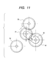
- Fig. 11 is the schematic side view showing the planet gear clutch to be used in the sheet material feeding apparatus according to the embodiment.
- a gear holder 32 is rotatably fit on the rotation center shaft of a sun gear 30 which is driven by a not-shown motor, and a planet gear 31 is rotatably fit on the end of the gear holder 32 so that the planet gear 31 engages with the sun gear 30.
- the planet gear 31 is structured so that, according to the rotation direction of the gear holder 32, the planet gear 31 can engage with an ASF first gear 33 (in case of rotating the gear holder 32 in a direction L) or a recovery-system first gear 34 (in case of rotating the gear holder 32 in a direction M).
- the ASF first gear 33 transmits the driving force to the ASF unit, i.e., the sheet material feeding apparatus of the embodiment, through a not-shown gear string, and the recovery-system first gear 34 transmits the driving force to a not-shown recovery-system unit.
- the ASF first gear 33 is rotated clockwise in Fig. 11, whereby the gear 33 is released from the engagement with the planet gear 31.
- the feeding roller 11 is rotated at the speed higher than the driving speed of the motor.
- the movement of the pressure plate 16 toward the direction apart from the feeding roller 11 is performed by the rotation of the pressure plate 16 which occurs when the cam 16a is pressed by the cam 22a according to the rotation of the feeding roller 11.
- the operation to urge/release the pressure plate 16 into/from the feeding roller 11 is performed at later-described predetermined timing, whereby the feeding operation in the sheet material feeding apparatus is performed.
- the pressure plate 16 By the operation that the pressure plate 16 is urged to and released from the feeding roller 11 at the predetermined timing as described above, the sheaf of the sheet materials stacked on the pressure plate 16 is pressed against the feeding roller 11. At the same time, since the feeding roller 11 is driven to rotate, the uppermost sheet material of the sheaf of the sheet materials stacked on the pressure plate 16 comes into contact with the feeding roller 11, whereby the uppermost sheet material is transported by frictional force between this sheet material and the feeding roller 11. Thus, since the feeding roller 11 transports the sheet material by the frictional force, rubber such as EPDM (ethylene-propylene-diene copolymer) or the like having a high friction coefficient, urethane foam and the like can be suitably used as the material of the feeding roller 11.
- EPDM ethylene-propylene-diene copolymer
- the mechanism to release the pressure plate 16 from the feeding roller 11 is structured by using the cam 22a provided coaxially with the feeding shaft gear 22. Equally, on the feeding shaft 10, the same cam is provided on the side opposite to the side of the feeding shaft gear 22 shown in Fig. 2, whereby the pressure plate 16 is rotated and moved uniformly by simultaneously pressing both the edges of the pressure plate 16 with these cams.
- the uppermost sheet material of the sheaf of the sheet materials stacked on the pressure plate 16 is fed and transported by the feeding roller 11.
- the frictional force between the feeding roller 11 and the uppermost sheet material is often larger than frictional force between the uppermost sheet material and the sheet material immediately below the uppermost sheet material, only the uppermost sheet material is often transported.
- the plural sheet materials might be drawn out at a time from the pressure plate 16 by the feeding roller 11. In this case, according to the embodiment, only the uppermost sheet is separated from the sheaf of the sheet materials stacked on the pressure plate 16 in the following way.
- the separation roller 12 is pressed against the feeding roller 11 so that the separation roller 12 comes into contact with the surface of the feeding roller 11 on a downstream side along the transporting direction where the sheet material first comes into contact with the feeding roller 11.
- the separation roller 12 itself is merely held rotatably by the holder 27, that is, the holder 27 does not actively drive the separation roller 12 to rotate.
- the spindle of the separation roller 12 is fixed, and a coil spring which is formed by metal, plastics or the like is held between the fixed spindle and the separation roller 12.
- the surface of the separation roller 12 is made by rubber, urethane foam or the like so that the separation roller 12 has the friction coefficient substantially the same as that of the feeding roller 11.
- the multifeeding prevention unit is provided in the sheet material feeding apparatus according to the embodiment.
- the multifeeding prevention unit is composed of the control cam 14, the turn-back levers 13 and the like of the above driving mechanism portion.
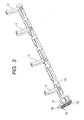
- Fig. 3 is a schematic perspective view showing the relation between the turn-back levers 13 and the control cam 14.
- the sheet material feeding apparatus is provided with the four turn-back levers 13, and, as shown in Fig. 3, these levers are mutually provided on a cylindrical rotative shaft 13b at regular intervals, and the levers 13 and the shaft 13b are integrally manufactured. Further, a hole into which one end of the shaft 13b is rotatably fit is formed on the control cam 14, and thus the control cam 14 is fit on the one end of the rotative shaft 13b coaxially by inserting the one end of this shaft into the hole on the control cam 14.
- a reentrant (recessed) notch into which a projection 13a extending from one end surface of the rotative shaft 13b is inserted as shown in Figs. 2 and 3 is formed like a circular arc, and thus a relative rotation angle between the rotative shaft 13b and the control cam 14 is regulated by engaging the projection 13a with the reentrant notch.
- a spring 24 is provided over the rotative shaft 13b and the control cam 14 to put these relative rotations aside to one direction.
- the turn-back levers 13 rotate in synchronism with the control cam 14. However, when the control cam 14 is fixed and the turn-back levers 13 are rotated in the direction opposite to the direction C of Fig. 2, the turn-back levers 13 can rotate and move independently of the control cam 14 by a predetermined angle range.
- the turn-back levers 13 operate in synchronism with the rotation of the control gear 23. Further, the basic operations of the turn-back levers 13 and the control gear 23 will be explained hereinafter.
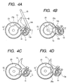
- Figs. 4A, 4B, 4C and 4D are side views showing the portion of the sheet material feeding apparatus which includes the control gear 23, the control cam 14 and the like, in order to explain the operation of the turn-back levers 13.
- Figs. 4A to 4D only the structural components necessary for the explanation are extracted from Fig. 2 and shown.
- each of the turn-back levers 13 can take three kinds of positions.
- Fig. 4A shows the state immediately after the feeding operation started. That is, immediately after the feeding operation started, since there is a possibility that the sheet material is newly stacked while the feeding is being on standby, an operation to return the leading edge of the newly stacked sheet material to the predetermined sheet material leading edge basis portion 15b is performed.
- the position of the turn-back lever 13 is the position which is most moved in the direction B of Fig. 4A. If the turn-back lever 13 reaches this position, the leading edge of the precedent sheet material is completely returned to the predetermined sheet material leading edge basis portion 15b.
- Fig. 4B shows the state that the turn-back lever 13 is most rotated and moved in the direction E.
- a projection 14a projected from the side surface of the control cam 14 comes into contact with a flange portion provided on the surface opposite to the side of the cam 23a of the control gear 23 and thus stops moving, whereby the turn-back lever 13 is set to the predetermined position.
- Fig. 4C shows the state that the control gear 23 is further rotated from the state shown in Fig. 4B in the direction D and the turn-back lever 13 is thus returned to the position shown in Fig. 4A during the feeding operation.
- the position itself of the turn-back lever 13 is substantially the same as the position shown in Fig. 4A.
- Fig. 4D shows the position of the turn-back lever 13 when the feeding operation of the sheet material feeding apparatus is on standby.
- the end of the turn-back lever 13 is inserted into the sheet material passing route as described above, whereby it is prevented that the leading edge of the sheet material carelessly enters the interior of the sheet material feeding apparatus in case of setting the sheet material to the sheet material feeding apparatus.
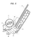
- Fig. 5 is the schematic sectional view of the sheet material feeding apparatus showing the standby state of Fig. 4D in association with the sheet material passing route. It should be noted that Fig. 5 shows the section along the alternate long and short dashed line D of Fig. 1 which is viewed from the direction B.
- a D-cut surface 11d extending in the direction parallel with the shaft of the feeding roller 11 is formed as a plane portion on the periphery of the feeding roller 11 so that the sectional shape of the feeding roller 11 becomes "D". Therefore, after the leading edge of the sheet material fed by the one-time rotation of the feeding roller 11 was grasped on the side of the body of the recording apparatus, the D-cut surface 11d is opposed to the separation roller 12, whereby an interspace is formed between the feeding roller 11 and the separation roller 12, and the latter half of the sheet material passes this interspace.
- the sheet material passing route is dog-legged as a whole, the sheet material starts coiling around the feeding roller 11 due to rigidity of the sheet material.
- the feeding roller 11 of which the surface friction coefficient is high comes into contact with the sheet material, whereby a serious friction load is given to the sheet material.
- the feeding roller 18 of which the friction coefficient with the sheet material is low and which easily rotates according to the sheet material is provided in the vicinity of the feeding roller 11 on the feeding shaft 10.
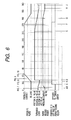
- Fig. 6 is the timing chart showing the operation of the sheet material feeding apparatus according to the embodiment. Concretely, Fig. 6 shows the position of the pressure plate 16, the position of the turn-back lever 13, the position of the separation roller 12, and the rotation angle of the feeding roller 11.
- the rotation angle 0° of the feeding roller 11 indicates the standby state shown in Fig. 5, that is, a series of operations starts from this standby state of Fig. 5.
- the pressure plate 16 is held at the position released (apart) from the feeding roller 11, i.e., a released position, and the turn-back lever 13 is at the position shown in Fig. 4D.
- the separation roller 12 is at the position retracted from the feeding roller 11, i.e., a retracted position, and the D-cut surface 11d of the feeding roller 11 is opposite to the separation roller 12.
- the control cam 28 is first operated, and the separation roller 12 starts moving from the retracted position to the pressure-contact position. At this time, the feeding roller 11, the separation roller 12 and the pressure plate 16 are in the state shown in Fig. 7.
- the turn-back lever 13 is moved to the position shown in Fig. 4A by the control cam 14 to start returning the leading edges of the sheet materials with possibility of becoming irregular on the sheet material feeding apparatus during the standby state, up to a sheet material leading edge basis portion 15b.
- the rotation angle of the feeding roller 11 comes to be in the vicinity of an angle C
- the curved surface portion of the feeding roller 11 is rotated to the position opposite to the separation roller 12, and at the same time the separation roller 12 moved toward the pressure-contact direction on the side of the feeding roller 11 completes its movement, whereby the curved surface portion of the feeding roller 11 comes into pressure-contact with the separation roller 12.
- the separation roller 12 moves according to the rotative movement of the feeding roller 11, the coil spring of the separation roller 12 is charged up to a predetermined torque.
- the rotation angle of the feeding roller 11 becomes an angle K
- the fixed pressure plate 16 is released, and the pressure plate 16 and the sheet materials set on this plate start moving in the direction toward the feeding roller 11.
- the feeding roller 11, the separation roller 12 and the pressure plate 16 are in the state shown in Fig. 8.
- the turn-back lever 13 moves to the position of Fig. 4B in one breath and thus completely retracts from the sheet material passing route.
- the turn-back lever 13 After the turn-back lever 13 retracted, through the states shown in Figs. 9 and 10, it causes an uppermost sheet material 19 of a sheaf of the sheet materials stacked on the pressure plate 16 as shown in Fig. 5 to come into pressure-contact with the feeding roller 11, and then the transportation of the sheet material is started as described above.
- the sheet materials are continuously transported one by one for a while, and, if the plural sheet materials are transported in the state that they overlap each other as above, the overlapping sheet materials are separated by the separation unit.
- the sheet materials are transported toward the body of the recording apparatus (in the direction A shown in Fig. 1). Then, the leading edge of the transported sheet material is grasped on the side of the recording apparatus, this sheet material is transported by the cooperation of the body of the recording apparatus and the feeding roller 11, and then the multifeeding prevention operation starts.
- the releasing operation of the pressure plate 16 is started. That is, if the pressure plate 16 is moved in the direction released (apart) from the feeding roller 11, the sheet material on the pressure plate 16 is released from the pressure-contact with the feeding roller 11, whereby the transportation force of the sheet material decreases. Further, immediately after this, the D-cut surface 11d of the feeding roller 11 becomes opposite to the pressure-plate portion on which the pressure plate 16 has been fit. However, since the separation roller 12 is still in pressure-contact with the feeding roller 11, the sheet materials are continuously being transported.
- the separation roller 12 starts releasing from the feeding roller 11 by the operation of the control cam 28. If the separation roller 12 is made apart from the feeding roller 11, the pressure-contact force of the feeding roller 11 to the sheet material vanishes, whereby the force to hold the sheet materials also vanishes on the side of the sheet material feeding apparatus, while the sheet materials are still held on the side of the body of the recording apparatus. Thus, the turn-back lever 13 starts entering the sheet material passing route just at timing that the sheet holding force vanishes.
- the leading edge of the next sheet material remains in the vicinity of the portion nipped between the feeding roller 11 and the separation roller 12, this leading edge of the sheet material is scraped (or scratched) off and then returned by the end of the turn-back lever 13.
- the sheet material feeding apparatus which separates the sheet materials one by one from the sheaf of the plural sheet materials stacked on the pressure plate 16 and then feeds the separated sheet materials by using the feeding roller 11 and the separation roller 12, it causes the separation roller 12 to come into contact with the feeding roller 11 when the pressure plate 16 is moved by the cam 22a on the rotating shaft of the feeding roller 11.
- the braking force applied from the separation roller 12 it is possible by the braking force applied from the separation roller 12 to prevent that the feeding roller 11 antecedently rotates.
- the friction separation system using the separation roller is used to separate the sheet materials
- the present invention is not limited to this. That is, it is needless to say that various kinds of separation systems such as a friction separation system using a friction pad and the like are applicable to the separation unit.
- the planet gear clutch is used to transmit the driving force also to the unit other than the sheet material feeding apparatus in the middle of this driving force transmission mechanism, however, the present invention is not limited to this. That is, it is needless to say that a spring clutch made by a spring and the like are applicable to the driving force transmission mechanism.
- the present invention is applied to the recording apparatus of serial type which moves the recording head in the main scanning direction.
- the present invention is applicable also to a recording apparatus of full-line type which records an image by a recording head extending to whole area along the recording sheet width direction as continuously transporting recording sheets.
- the above embodiment is explained with respect to the example that the recording head to which a so-called BJ (bubble-jet) system of various kinds of ink-jet systems is applied is used.
- BJ bubble-jet
- the present invention is applicable not only to such a recording head recording system but also to the various recording systems.
- a piezoelectric system may be used as well as the BJ system.
- the sheet material feeding apparatus which separates the sheet materials one by one from the sheaf of the plural sheet materials stacked on the stacking unit and then transports the separated sheet materials by using the feeding roller and the friction separation means, it causes the friction separation means to come into contact with the feeding roller when the pressing member to press and cause the sheet material on the stacking unit to come into contact with the feeding roller is moved by the cam member on the rotating shaft of the feeding roller.
- the driving force is applied from the driving source to the feeding roller through the clutch means, the phenomenon that the feeding roller antecedently rotates can be prevented by the braking force applied from the friction separation means, whereby it becomes unnecessary to provide the driving source dedicated for the sheet material feeding apparatus.
- a sheet material feeding apparatus provided with a simple-structure and low-cost multifeeding prevention mechanism, comprises a sheet stacker for stacking sheets, a feeding roller for feeding the stacked sheets, a separation roller, rotating according to the feeding roller, for separating the sheet, a separation roller holder for rotatably holding the separation roller and rotating to cause the separation roller to move to a position being in contact with the feeding roller and to a position being released from the feeding roller, and a urge unit for urge the sheet stacker to the feeding roller to cause the stacked sheets to come into contact with the feeding roller, wherein, after the separation roller came into contact with the feeding roller, it causes the stacked sheets to come into contact with the feeding roller.
Landscapes
- Sheets, Magazines, And Separation Thereof (AREA)
Abstract
Description
Claims (16)
- A sheet material feeding apparatus comprising:wherein, after said separation roller came into contact with said feeding roller, it causes the sheet materials stacked on said sheet material stacking means to come into contact with said feeding roller.sheet material stacking means for stacking sheet materials;a feeding roller for feeding the sheet materials stacked on said sheet material stacking means;a separation roller, rotating according to said feeding roller, for separating the sheet material;a separation roller holder for rotatably holding said separation roller, said separation roller holder rotating to cause said separation roller to move to a position being in contact with said feeding roller and to a position being released from said feeding roller; andurging means for urging said sheet material stacking means to said feeding roller to cause the sheet materials stacked on said sheet material stacking means to come into contact with said feeding roller,
- An apparatus according to Claim 1, further comprising turn-back means for returning the sheet materials other than the sheet materials separated by said separation roller to said sheet material stacking means.
- An apparatus according to Claim 1, wherein said separation roller is provided with a torque limiter.
- An apparatus according to Claim 1, wherein said separation roller is provided with urging means for causing said separation roller to come into pressure-contact with said feeding roller.
- An apparatus according to Claim 1, wherein said separation roller comes into contact with said feeding roller on a downstream side of a position where said feeding roller comes into contact with said sheet material stacking means.
- An apparatus according to Claim 1, wherein a driving force from a driving source is transmitted to said feeding roller through clutch means for intermitting transmission of the driving force.
- An apparatus according to Claim 6, wherein said clutch means includes a planet gear clutch.
- An apparatus according to Claim 6, wherein said clutch means includes a spring clutch composed by using a spring.
- A recording apparatus which performs recording on a sheet material by using a recording head, comprising:wherein, after said separation roller came into contact with said feeding roller, it causes the sheet materials stacked on said sheet material stacking means to come into contact with said feeding roller.a head mounting unit for mounting the recording head;sheet material stacking means for stacking sheet materials;a feeding roller for feeding the sheet materials stacked on said sheet material stacking means;a separation roller, rotating according to said feeding roller, for separating the sheet material;a separation roller holder for rotatably holding said separation roller, said separation roller holder rotating to cause said separation roller to move to a position being in contact with said feeding roller and to a position being released from said feeding roller; andurging means for urging said sheet material stacking means to said feeding roller to cause the sheet materials stacked on said sheet material stacking means to come into contact with said feeding roller,
- An apparatus according to Claim 9, further comprising turn-back means for returning the sheet materials other than the sheet materials separated by said separation roller to said sheet material stacking means.
- An apparatus according to Claim 9, wherein said separation roller is provided with a torque limiter.
- An apparatus according to Claim 9, wherein said separation roller is provided with urging means for causing said separation roller to come into pressure-contact with said feeding roller.
- An apparatus according to Claim 9, wherein said separation roller comes into contact with said feeding roller on a downstream side of a position where said feeding roller comes into contact with said sheet material stacking means.
- An apparatus according to Claim 9, wherein a driving force from a driving source is transmitted to said feeding roller through clutch means for intermitting transmission of the driving force.
- An apparatus according to Claim 14, wherein said clutch means includes a planet gear clutch.
- An apparatus according to Claim 14, wherein said clutch means includes a spring clutch composed by using a spring.
Applications Claiming Priority (2)
| Application Number | Priority Date | Filing Date | Title |
|---|---|---|---|
| JP2001139898 | 2001-05-10 | ||
| JP2001139898 | 2001-05-10 |
Publications (3)
| Publication Number | Publication Date |
|---|---|
| EP1256456A2 true EP1256456A2 (en) | 2002-11-13 |
| EP1256456A3 EP1256456A3 (en) | 2003-08-20 |
| EP1256456B1 EP1256456B1 (en) | 2005-11-30 |
Family
ID=18986596
Family Applications (1)
| Application Number | Title | Priority Date | Filing Date |
|---|---|---|---|
| EP02010444A Expired - Lifetime EP1256456B1 (en) | 2001-05-10 | 2002-05-08 | Sheet material feeding apparatus and recording apparatus |
Country Status (3)
| Country | Link |
|---|---|
| US (1) | US6896253B2 (en) |
| EP (1) | EP1256456B1 (en) |
| DE (1) | DE60207630T2 (en) |
Cited By (1)
| Publication number | Priority date | Publication date | Assignee | Title |
|---|---|---|---|---|
| CN108650884A (en) * | 2016-04-18 | 2018-10-12 | 惠普发展公司,有限责任合伙企业 | Pressing plate controls |
Families Citing this family (19)
| Publication number | Priority date | Publication date | Assignee | Title |
|---|---|---|---|---|
| JP3919549B2 (en) * | 2002-01-31 | 2007-05-30 | キヤノン株式会社 | Recording device |
| US7165765B2 (en) * | 2002-06-07 | 2007-01-23 | Canon Kabushiki Kaisha | Sheet feeding apparatus and recording apparatus |
| JP4072397B2 (en) * | 2002-08-16 | 2008-04-09 | キヤノン株式会社 | Automatic feeding apparatus and recording apparatus provided with the same |
| JP2004075356A (en) * | 2002-08-21 | 2004-03-11 | Canon Inc | Sheet material guide mechanism, sheet material feeding device provided with the same, and recording device |
| JP2005075525A (en) * | 2003-08-29 | 2005-03-24 | Canon Inc | Sheet material feeding device and recording device |
| JP4432564B2 (en) * | 2004-03-23 | 2010-03-17 | ブラザー工業株式会社 | Printer |
| US7131644B2 (en) * | 2004-04-06 | 2006-11-07 | Lexmark International, Inc. | Imaging apparatus having an automatic sheet feeder |
| US7128317B2 (en) * | 2004-09-10 | 2006-10-31 | Lexmark International, Inc. | Moveable media dam |
| JP4428179B2 (en) * | 2004-09-27 | 2010-03-10 | セイコーエプソン株式会社 | Recording material guide device |
| US7226048B2 (en) * | 2004-09-29 | 2007-06-05 | Lexmark International, Inc. | Imaging apparatus having a print media dam in association with an automatic sheet feeder mechanism |
| JP4444876B2 (en) * | 2005-04-28 | 2010-03-31 | キヤノン株式会社 | Image reading and recording device |
| TWI271313B (en) * | 2005-05-12 | 2007-01-21 | Benq Corp | Paper-feeding mechanism |
| TWI304021B (en) * | 2006-09-08 | 2008-12-11 | Qisda Corp | Media-feed mechanisms |
| US7665724B2 (en) * | 2007-03-08 | 2010-02-23 | Hewlett-Packard Development Company, L.P. | Kicker |
| JP4826812B2 (en) * | 2007-06-20 | 2011-11-30 | セイコーエプソン株式会社 | Feeding device, recording device |
| JP5213529B2 (en) * | 2008-06-09 | 2013-06-19 | キヤノン株式会社 | Image processing device |
| US8215633B2 (en) * | 2010-08-30 | 2012-07-10 | Eastman Kodak Company | Media stopper method for a printing system |
| US8328183B2 (en) * | 2010-08-30 | 2012-12-11 | Eastman Kodak Company | Media stopper for a printing system |
| JP5721493B2 (en) * | 2011-03-24 | 2015-05-20 | キヤノン株式会社 | Sheet feeding apparatus and image forming apparatus |
Family Cites Families (32)
| Publication number | Priority date | Publication date | Assignee | Title |
|---|---|---|---|---|
| US4627607A (en) * | 1982-10-15 | 1986-12-09 | Ricoh Company, Ltd. | Sheet feeding system |
| EP0204227B1 (en) * | 1985-05-24 | 1990-09-12 | Mita Industrial Co. Ltd. | Paper feeding device |
| JPH0825645B2 (en) * | 1987-10-28 | 1996-03-13 | ミノルタ株式会社 | Automatic paper feeder |
| JPH03256944A (en) * | 1990-03-05 | 1991-11-15 | Ricoh Co Ltd | Sheet overlap feed inhibiting roller |
| JP2966054B2 (en) * | 1990-07-13 | 1999-10-25 | キヤノン株式会社 | Sheet feeding device |
| JPH04164723A (en) * | 1990-10-29 | 1992-06-10 | Ricoh Co Ltd | Document tip alignment device for facsimile |
| JP2943415B2 (en) * | 1991-03-19 | 1999-08-30 | キヤノン株式会社 | Paper feeder and image forming apparatus using the same |
| US5244191A (en) * | 1991-07-08 | 1993-09-14 | Matsushita Electric Industrial Co., Ltd. | Sheet feeding apparatus for image recording system |
| US5358230A (en) * | 1992-04-24 | 1994-10-25 | Canon Kabushiki Kaisha | Sheet supplying apparatus |
| US5351945A (en) * | 1992-05-30 | 1994-10-04 | Mita Industrial Co., Ltd. | Overlapped transfer-preventing mechanism |
| DE69307410T2 (en) * | 1992-06-30 | 1997-05-22 | Canon Kk | Automatic sheet feeder |
| JP2950158B2 (en) * | 1993-12-29 | 1999-09-20 | キヤノン株式会社 | Paper feeder and recording device |
| EP0694490B1 (en) * | 1994-07-29 | 2000-05-31 | Canon Kabushiki Kaisha | Sheet supply apparatus |
| JP3309616B2 (en) * | 1994-12-26 | 2002-07-29 | セイコーエプソン株式会社 | Paper feeder |
| JPH08277046A (en) * | 1995-04-10 | 1996-10-22 | Canon Inc | Paper feeding / conveying device and recording apparatus including the paper feeding / conveying device |
| JPH0986705A (en) * | 1995-07-18 | 1997-03-31 | Mitsubishi Electric Corp | Automatic paper feeder |
| US5655762A (en) * | 1995-08-24 | 1997-08-12 | Hewlett-Packard Company | Mechanism for avoiding multiple sheet misfeeds in sheet media feed systems |
| EP0761581B1 (en) * | 1995-08-28 | 2003-05-02 | Canon Kabushiki Kaisha | Sheet supplying apparatus |
| JP3521102B2 (en) * | 1996-02-27 | 2004-04-19 | 株式会社リコー | Paper feeder |
| JPH09323839A (en) * | 1996-06-06 | 1997-12-16 | Canon Inc | Sheet material supply device and image forming apparatus |
| EP0816107B1 (en) * | 1996-06-25 | 2000-09-06 | Seiko Epson Corporation | Paper feeding apparatus and printer |
| US5882004A (en) * | 1996-09-18 | 1999-03-16 | Hewlett-Packard Co. | Automatic sheet feeding mechanism |
| US6059281A (en) * | 1996-10-03 | 2000-05-09 | Canon Kabushiki Kaisha | Sheet feeding apparatus |
| JPH1159939A (en) * | 1997-08-07 | 1999-03-02 | Mitsubishi Electric Corp | Automatic paper feeder |
| US6354584B1 (en) * | 1998-10-14 | 2002-03-12 | Canon Kabushiki Kaisha | Sheet feeding apparatus, image forming apparatus having the same and image reading apparatus having the same |
| JP2000143023A (en) * | 1998-11-04 | 2000-05-23 | Canon Inc | Paper feeder and image forming apparatus |
| US6135444A (en) * | 1998-12-15 | 2000-10-24 | Hewlett-Packard Company | Automatic sheet feeding mechanism |
| JP3368248B2 (en) * | 1999-05-13 | 2003-01-20 | キヤノン株式会社 | Sheet feeding apparatus, and image forming apparatus and image reading apparatus provided with the apparatus |
| US6382622B1 (en) * | 1999-05-13 | 2002-05-07 | Canon Kabushiki Kaisha | Sheet feeding apparatus, image forming apparatus having the same, and image reading apparatus having the same |
| JP2001163472A (en) * | 1999-09-30 | 2001-06-19 | Canon Inc | Sheet feeding apparatus, image forming apparatus provided with the apparatus, and image reading apparatus |
| JP3733841B2 (en) * | 2000-07-06 | 2006-01-11 | セイコーエプソン株式会社 | Sheet feeding device |
| JP3720706B2 (en) * | 2000-12-18 | 2005-11-30 | キヤノン株式会社 | Sheet feeding apparatus, image forming apparatus including the same, and image reading apparatus |
-
2002
- 2002-05-03 US US10/137,378 patent/US6896253B2/en not_active Expired - Fee Related
- 2002-05-08 EP EP02010444A patent/EP1256456B1/en not_active Expired - Lifetime
- 2002-05-08 DE DE60207630T patent/DE60207630T2/en not_active Expired - Lifetime
Cited By (3)
| Publication number | Priority date | Publication date | Assignee | Title |
|---|---|---|---|---|
| CN108650884A (en) * | 2016-04-18 | 2018-10-12 | 惠普发展公司,有限责任合伙企业 | Pressing plate controls |
| US10543700B2 (en) | 2016-04-18 | 2020-01-28 | Hewlett-Packard Development Company, L.P. | Pressure plate control |
| CN108650884B (en) * | 2016-04-18 | 2020-11-20 | 惠普发展公司,有限责任合伙企业 | Platen Control |
Also Published As
| Publication number | Publication date |
|---|---|
| DE60207630T2 (en) | 2006-07-20 |
| US6896253B2 (en) | 2005-05-24 |
| US20020167124A1 (en) | 2002-11-14 |
| EP1256456B1 (en) | 2005-11-30 |
| DE60207630D1 (en) | 2006-01-05 |
| EP1256456A3 (en) | 2003-08-20 |
Similar Documents
| Publication | Publication Date | Title |
|---|---|---|
| EP1256456B1 (en) | Sheet material feeding apparatus and recording apparatus | |
| US6824132B2 (en) | Sheet feeding apparatus and recording apparatus | |
| EP0580431B1 (en) | Paper feeding apparatus for printer | |
| US7621522B2 (en) | Sheet feeding device | |
| JPH0262451B2 (en) | ||
| US9617093B2 (en) | Paper feeder, image reading apparatus and image forming apparatus including the same | |
| US5524994A (en) | Paper skew removal apparatus and a printer using the same | |
| JP3598192B2 (en) | Drive | |
| US5746426A (en) | Feeding device having a feed roller with a low coefficient portion | |
| JP5213740B2 (en) | Drive transmission device and feeding device | |
| US20040070137A1 (en) | Automatic feeding device and recording apparatus provided wish such automatic feeding device | |
| EP0764602B1 (en) | Sheet separator apparatus | |
| JP2916044B2 (en) | Sheet material feeding device | |
| US7753362B2 (en) | Sheet feeding apparatus and recording apparatus | |
| US5630579A (en) | Automatic manuscript sheet feeder | |
| JP3135356B2 (en) | Paper feeder | |
| JPH0444509Y2 (en) | ||
| JP4035369B2 (en) | Sheet material feeding apparatus and recording apparatus | |
| JP2004182417A (en) | Automatic paper feeder | |
| JP2002332130A (en) | Sheet material feeding device, sheet material feeding method, and recording device | |
| JP3149894B2 (en) | Paper feeder in printer | |
| JP4454869B2 (en) | Sheet feeding device | |
| JP2003026340A (en) | Sheet material feeding device and recording device | |
| JP2001099196A (en) | Drive transmitting mechanism | |
| JP2003182862A (en) | Sheet feeding apparatus and image forming apparatus having the same |
Legal Events
| Date | Code | Title | Description |
|---|---|---|---|
| PUAI | Public reference made under article 153(3) epc to a published international application that has entered the european phase |
Free format text: ORIGINAL CODE: 0009012 |
|
| AK | Designated contracting states |
Kind code of ref document: A2 Designated state(s): AT BE CH CY DE DK ES FI FR GB GR IE IT LI LU MC NL PT SE TR |
|
| AX | Request for extension of the european patent |
Free format text: AL;LT;LV;MK;RO;SI |
|
| PUAL | Search report despatched |
Free format text: ORIGINAL CODE: 0009013 |
|
| AK | Designated contracting states |
Designated state(s): AT BE CH CY DE DK ES FI FR GB GR IE IT LI LU MC NL PT SE TR |
|
| AX | Request for extension of the european patent |
Extension state: AL LT LV MK RO SI |
|
| RIC1 | Information provided on ipc code assigned before grant |
Ipc: 7B 41J 13/10 A Ipc: 7B 41J 13/00 B |
|
| 17P | Request for examination filed |
Effective date: 20040105 |
|
| 17Q | First examination report despatched |
Effective date: 20040212 |
|
| AKX | Designation fees paid |
Designated state(s): DE FR GB IT |
|
| GRAP | Despatch of communication of intention to grant a patent |
Free format text: ORIGINAL CODE: EPIDOSNIGR1 |
|
| GRAS | Grant fee paid |
Free format text: ORIGINAL CODE: EPIDOSNIGR3 |
|
| GRAA | (expected) grant |
Free format text: ORIGINAL CODE: 0009210 |
|
| AK | Designated contracting states |
Kind code of ref document: B1 Designated state(s): DE FR GB IT |
|
| REG | Reference to a national code |
Ref country code: GB Ref legal event code: FG4D |
|
| REF | Corresponds to: |
Ref document number: 60207630 Country of ref document: DE Date of ref document: 20060105 Kind code of ref document: P |
|
| ET | Fr: translation filed | ||
| PLBE | No opposition filed within time limit |
Free format text: ORIGINAL CODE: 0009261 |
|
| STAA | Information on the status of an ep patent application or granted ep patent |
Free format text: STATUS: NO OPPOSITION FILED WITHIN TIME LIMIT |
|
| 26N | No opposition filed |
Effective date: 20060831 |
|
| PGFP | Annual fee paid to national office [announced via postgrant information from national office to epo] |
Ref country code: IT Payment date: 20080520 Year of fee payment: 6 |
|
| PG25 | Lapsed in a contracting state [announced via postgrant information from national office to epo] |
Ref country code: IT Free format text: LAPSE BECAUSE OF NON-PAYMENT OF DUE FEES Effective date: 20080508 |
|
| PGFP | Annual fee paid to national office [announced via postgrant information from national office to epo] |
Ref country code: FR Payment date: 20090520 Year of fee payment: 8 |
|
| REG | Reference to a national code |
Ref country code: FR Ref legal event code: ST Effective date: 20110131 |
|
| PG25 | Lapsed in a contracting state [announced via postgrant information from national office to epo] |
Ref country code: FR Free format text: LAPSE BECAUSE OF NON-PAYMENT OF DUE FEES Effective date: 20100531 |
|
| PGFP | Annual fee paid to national office [announced via postgrant information from national office to epo] |
Ref country code: DE Payment date: 20150531 Year of fee payment: 14 Ref country code: GB Payment date: 20150528 Year of fee payment: 14 |
|
| REG | Reference to a national code |
Ref country code: DE Ref legal event code: R119 Ref document number: 60207630 Country of ref document: DE |
|
| GBPC | Gb: european patent ceased through non-payment of renewal fee |
Effective date: 20160508 |
|
| PG25 | Lapsed in a contracting state [announced via postgrant information from national office to epo] |
Ref country code: DE Free format text: LAPSE BECAUSE OF NON-PAYMENT OF DUE FEES Effective date: 20161201 |
|
| PG25 | Lapsed in a contracting state [announced via postgrant information from national office to epo] |
Ref country code: GB Free format text: LAPSE BECAUSE OF NON-PAYMENT OF DUE FEES Effective date: 20160508 |