EP1256362B1 - Basketballkorb mit Torsionsfeder - Google Patents
Basketballkorb mit Torsionsfeder Download PDFInfo
- Publication number
- EP1256362B1 EP1256362B1 EP02394053A EP02394053A EP1256362B1 EP 1256362 B1 EP1256362 B1 EP 1256362B1 EP 02394053 A EP02394053 A EP 02394053A EP 02394053 A EP02394053 A EP 02394053A EP 1256362 B1 EP1256362 B1 EP 1256362B1
- Authority
- EP
- European Patent Office
- Prior art keywords
- torsion rod
- rim
- mounting bracket
- backboard
- rim member
- Prior art date
- Legal status (The legal status is an assumption and is not a legal conclusion. Google has not performed a legal analysis and makes no representation as to the accuracy of the status listed.)
- Expired - Lifetime
Links
- 230000007797 corrosion Effects 0.000 description 7
- 238000005260 corrosion Methods 0.000 description 7
- 238000004519 manufacturing process Methods 0.000 description 6
- 238000009434 installation Methods 0.000 description 4
- 229910000831 Steel Inorganic materials 0.000 description 3
- 238000012423 maintenance Methods 0.000 description 3
- 239000010959 steel Substances 0.000 description 3
- 229910000851 Alloy steel Inorganic materials 0.000 description 2
- 230000000712 assembly Effects 0.000 description 2
- 238000000429 assembly Methods 0.000 description 2
- 230000007812 deficiency Effects 0.000 description 2
- 239000000463 material Substances 0.000 description 2
- 230000002411 adverse Effects 0.000 description 1
- 230000003466 anti-cipated effect Effects 0.000 description 1
- 238000005452 bending Methods 0.000 description 1
- 230000000052 comparative effect Effects 0.000 description 1
- 239000011521 glass Substances 0.000 description 1
- 238000003698 laser cutting Methods 0.000 description 1
- 230000005923 long-lasting effect Effects 0.000 description 1
- 238000005461 lubrication Methods 0.000 description 1
- 239000002184 metal Substances 0.000 description 1
- 238000000034 method Methods 0.000 description 1
- 238000004513 sizing Methods 0.000 description 1
- 238000003466 welding Methods 0.000 description 1
Images




Classifications
-
- A—HUMAN NECESSITIES
- A63—SPORTS; GAMES; AMUSEMENTS
- A63B—APPARATUS FOR PHYSICAL TRAINING, GYMNASTICS, SWIMMING, CLIMBING, OR FENCING; BALL GAMES; TRAINING EQUIPMENT
- A63B63/00—Targets or goals for ball games
- A63B63/08—Targets or goals for ball games with substantially horizontal opening for ball, e.g. for basketball
- A63B63/083—Targets or goals for ball games with substantially horizontal opening for ball, e.g. for basketball for basketball
-
- A—HUMAN NECESSITIES
- A63—SPORTS; GAMES; AMUSEMENTS
- A63B—APPARATUS FOR PHYSICAL TRAINING, GYMNASTICS, SWIMMING, CLIMBING, OR FENCING; BALL GAMES; TRAINING EQUIPMENT
- A63B63/00—Targets or goals for ball games
- A63B63/08—Targets or goals for ball games with substantially horizontal opening for ball, e.g. for basketball
- A63B63/083—Targets or goals for ball games with substantially horizontal opening for ball, e.g. for basketball for basketball
- A63B2063/086—Targets or goals for ball games with substantially horizontal opening for ball, e.g. for basketball for basketball deflectable under excessive loads
-
- A—HUMAN NECESSITIES
- A63—SPORTS; GAMES; AMUSEMENTS
- A63B—APPARATUS FOR PHYSICAL TRAINING, GYMNASTICS, SWIMMING, CLIMBING, OR FENCING; BALL GAMES; TRAINING EQUIPMENT
- A63B2208/00—Characteristics or parameters related to the user or player
- A63B2208/12—Characteristics or parameters related to the user or player specially adapted for children
Definitions
- the present invention relates to basketball rim assemblies, and, in particular, to such assemblies which are designed to flex or give way to relieve excessive loads that are applied to the rim without transmitting the loads to the backboard.
- “Breakaway” basketball rims are intended to prevent damage to the rim assembly and/or the backboard when a player applies excessive downward force to the rim. This commonly occurs when a player slams the rim during a "dunk” shot, or when a player grabs the rim and hangs from it. Unless the resulting downward loads are absorbed and dissipated by the rim assembly, either the circular rim (hoop) may bend or the backboard (which is commonly made of glass) may break or shatter; in that case, the rim and/or backboard must be replaced, which is both expensive and causes a significant time delay before play can be resumed.
- a typical prior art rim 01 includes a series of loops or hooks 02 that are mounted along its lower edge for attachment on the net (not shown).
- the hooks or loops may be formed individually or as part of a continuous wire 03, but in either case the wire must be bent to form the hooks/loops and must then be welded to the bottom edge of the steel hoop.
- a separate prop rod 04 or similar support is also often welded between the bottom of the hoop and the mounting bracket 05 to provide the assembly with sufficient strength and rigidity.
- the present invention has solved the problems cited above, and is a breakaway basketball rim assembly in which the mechanism for allowing the rim to deflect downwardly and then returning it to a horizontal position comprises at least one torsion rod that twists resiliently under the load.
- the assembly comprises a base member, a rim member having a hoop portion for extending in a generally horizontal plane, and at least one torsion rod operably interconnecting with the rim member and the base member, the torsion rod having a first end which is mounted to the base member and a second end which is mounted to the rim member so as to be pivotable relative to the base member, so that in response to a downward impact on the hoop portion the torsion rod twists resiliently to permit the rim member to deflect downwardly relative to the base member.
- the base member may comprise a mounting bracket for attachment to a generally vertical backboard.
- the at least one torsion rod may comprise a transverse torsion rod for extending generally parallel to the backboard when the assembly is mounted thereto, the transverse torsion rod having a first end which is suitably mounted to the mounting bracket and a second end which is mounted to the rim member, so that the torsion rod permits the rim member to deflect downwardly about an axis which extends generally parallel to the backboard.
- the first end of the transverse torsion rod may be fixedly mounted to a forwardly projection flange portion of the mounting bracket and may pass through a cooperating bore in a rearwardly projecting flange portion of the rim member, and the second end of the rod may be fixedly mounted to a rearwardly projecting flange portion of the rim member and may pass through a cooperating bore in a forwardly projecting flange portion of the mounting bracket.
- Each end of the torsion rod may comprise a cylindrical exterior portion for pivotably engaging the bore through which the end of the rod passes, so that the first end of the transverse torsion rod supports the flange portion on the rim member in pivoting engagement therewith, and the second end of the torsion rod is supported by the flange portion on the mounting bracket in pivoting engagement therewith.
- the rim assembly may further comprise a longitudinal torsion rod for extending generally perpendicular to the backboard, the longitudinal torsion rod having a first end mounted to the mounting bracket and a second end mounted to the rim member, so that the longitudinal torsion rod permits the rim assembly to deflect downwardly about an axis extending generally perpendicular to the backboard.
- the transverse torsion rod may be mounted to the second, outer end of the longitudinal torsion rod.
- the mounting bracket may further comprise a support strut having an outer end in pivoting engagement with the longitudinal torsion rod, for supporting the longitudinal torsion rod against downward loads transmitted from the rim member.
- the rim member may further comprise a depending flange portion mounted to the hoop portion and having a plurality of through openings with mounting structures for attachment of a basketball net thereto.
- the mounting structures may comprise first and second attachment members which extend upwardly from the bottom edge of the opening, the attachment members being spaced apart from one another and from first and second side edges of the opening so as to define the central gap and first and second receiving areas for receiving and holding an attachment loop of the net therein.
- the attachment members may comprise first and second hook members that face outwardly in opposite directions so as to define the gap and receiving areas.
- the attachment members may also comprise first and second generally vertical post members which are spaced apart so as to define the central gap, and first and second generally horizontal post members which extend outwardly from the vertical post members so as to define the receiving areas.
- the breakaway basketball rim assembly may comprise a support bracket for mounting to a generally vertical backboard, the support bracket having first and second parallel, forwardly extending flange portions; a rim member having a hoop portion for extending in a generally horizontal plane and first and second parallel, rearwardly extending flange portions; and a transverse torsion rod extending generally perpendicular to the flange portions in parallel to the backboard, the transverse torsion rod having first and second ends with cylindrical exteriors formed thereon, the first end of the torsion rod being fixedly mounted to a flange portion of the mounting bracket and passing through a cooperating bore in a flange portion of the rim member so that its cylindrical exterior is in pivotable engagement therewith, and the second end of the torsion rod being fixedly mounted to a flange portion of the rim member and passing through a cooperating bore in a flange portion of the mounting bracket so that its cylindrical exterior thereon is in pivotable engagement therewith, so that the pivotable
- the breakaway basketball rim assembly may comprise a mounting bracket for attachment to a generally vertical backboard; a rim member having a hoop portion for extending in a generally horizontal plane and further having first and second substantially parallel, rearwardly extending flange portions; a first, longitudinal torsion rod for extending generally perpendicular to the backboard, the longitudinal torsion rod having a first end fixedly mounted to the mounting bracket and a second end extending forwardly therefrom and having a cylindrical exterior surface formed thereon; a support strut having a first end mounted to the mounting bracket and a second end having a bore in which the cylindrical surface on the second end of the torsion rod is received in pivoting engagement, so that the strut supports the second end of the longitudinal torsion rod against downward loads transferred from the rim member; a transverse support tube mounted to the second end of the longitudinal torsion rod so as to extend at substantially right angles thereto, the support tube having a generally cylindrical internal bore; and a second, transverse torsion rod mounted
- FIG. 1 shows a breakaway basketball rim assembly 10 in accordance with the present invention.
- This embodiment is a single axis assembly, so that the rim 12 bends downwardly about a single axis in response to a downward force, as indicated by arrow 14.
- the assembly includes a base bracket 16 that is mounted to the backboard 18 by bolts or other suitable means.
- the stationary bracket is U-shaped and has first and second forwardly projecting flanges 20a, 20b that extend on either side of a pivoting bracket 22 that is mounted and extended variably from the rim 12.
- the stationary and pivoting brackets 16, 22 are interconnected by a torsion rod pivot mechanism 24, as will be described in greater detail below.
- This arrangement of overlapping flanges/brackets provides a particularly strong and easily fabricated structure, however, it will be understood that any other suitable structure may be used to connect the ends of the torsion rod or rods to the rim and the stationary support in accordance with the present invention.
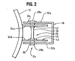
- the torsion bar pivot mechanism can be more clearly seen in FIG. 2.
- This includes a torsion rod 26 having first and second cylindrical end portions 28a, 28b, and a "necked down" cylindrical middle portion 30.
- the torsion rod is suitably formed of heat-treated steel, such as heat-treated 4130-alloy steel, for example.
- the term "torsion rod” includes all rods, bars, plates and similar members that deflect torsionally and resiliently in response to a twisting or turning force, whether having an elongate, cylindrical shape as shown in the drawings or some other configuration.
- the cylindrical end portions 28a, 28b of the torsion rod are somewhat elongate and pass through bore in first and second flanges or plates on either side of the assembly.
- the outer plates 32a, 32b are formed by the forwardly projecting flanges of the stationary bracket 16, and the inner plates 34a, 34b are formed by the rearwardly projecting flanges of the pivoting bracket 22.
- the first end 28a of the torsion rod is fixedly mounted to the flange 32a of the stationary bracket by a weld 36 or other suitable means, while the opposite end of the torsion rod is free to rotate within a cooperating bore 38 in the opposite stationary flange 32b.
- This end of the rod is fixedly attached to the inner flange 34b of the pivoting bracket, by a weld 40 or other suitable means, while the other end 28a of the rod is free to pivot within the cooperating bore 42 formed in the opposite rearward flange 34a.
- the second end 28b of the torsion rod pivots with the rim while its first end 28a remains stationary, so that the center portion 30 of the torsion rod is resiliently twisted by the load thereon.
- the torsional loading of the rod 26 is illustrated in FIG. 3.
- the angle ⁇ of rotation between the fixed and rotating rods is preferably confined to no more than about 15° (approximately 41 ⁇ 2 %) to avoid exceeding the yield stress of the rod, so that the rod returns resiliently to its initial orientation upon release.
- the suitable material for use in the rod is 4130 heat-treated alloy steel, which provides a suitable degree of resilience while still being able to be welded with comparative ease, although it will be understood that other suitable metallic and nonmetallic materials will occur to those skilled in the art.
- the sizing of the rod itself will depend anticipated loads and other factors; exemplary dimensions may be in the range from about 10,16-25,4 cm (4-10") long and about 0,95-2,54 cm (3/8 - 1") in diameter (in the middle portion 30), however it will be understood that a torsion rod or rods having any dimensions that yield suitable torsion characteristics may be used.
- the middle portion 30 of the rod is configured to provide the desired torsional characteristics, while the ends 28a, 28b of the rod are somewhat larger in diameter: The enlarged ends form larger, longer-wearing bearing surfaces where these engage the cooperating bores in the plates, and also provide an enlarged area/circumference for welding at the fixed mounting points.
- a breakaway rim assembly constructed in accordance with the embodiment described above has been found to absorb impact loads exerted by a 113,4 kg (250-lb+) player, and exhibits excellent deflection and return characteristics. Moreover, as compared with the prior art devices described above, the assembly is comparatively simple and inexpensive to construct, and requires little or no maintenance. Moreover, the assembly is virtually unaffected by corrosion and is therefore suitable for outdoor installations; in the event that corrosion develops between the pivot points at the ends of the torsion rod during an extended period of nonuse, this is immediately broken free with very little resistance the first time that the assembly is impacted or struck during play.
- FIG. 4 shows a pivot assembly 50 is accordance with another embodiment of the present invention, in which there are first and second torsion rods 52, 54 arranged at right angles so as to allow deflection along first and second axes.
- Each of the torsion rods 52, 54 is substantially similar to the torsion rod 26 described above in overall configuration, although it will be understood that these are preferably sized to provide suitable resistance when working in concert.
- the first, longitudinal torsion rod 52 extends perpendicular to the backboard, with its first end 56a being fixedly mounted to a stationary base plate 58, as by weld 59.
- a support strut 60 is also mounted to the stationary base plate and extends forwardly to the outer end of the longitudinal torsion rod.
- Bores 62a, 62b are formed in upwardly extending flanges 64a, 64b on the end of the strut for receiving and supporting the outer end 56b of the rod in pivoting engagement therewith, with the result that the strut 60 supports the outer end of the first torsion rod 52 against downward loads transmitted from the rim.
- the second torsion rod 54 resides inside the transverse tube, with its enlarged, cylindrical end portions 72a, 72b engaging the interior of the tube and projecting outwardly from the ends thereof.
- the ends of the tube members are flanked by first and second flange plates 70a, 70b that are mounted to the rim 12, and the projecting ends 72a, 72b of the transverse torsion rod pass through corresponding openings in the plates.
- the first end 72a of the transverse torsion rod is fixedly mounted to the first flange bracket 70a (by weld 74), but is in pivotable engagement with the bore 76 of the tube member.
- the opposite end 72b of the rod is fixedly mounted to its end of the tube member (by weld 76), but is received rotatably in the bore 78 of the second flange plate 70b.
- the fixed end 72b of the transverse torsion rod 54 remains stationary while the opposite end 72a rotates downwardly under the load.
- the first flange plate 70a pivots downwardly with the rotating end of the rod while the opposite flange plate 70 pivots on bore 78.
- the assembly 50 is able to deflect downwardly in response to downward loading of the rim 12, about a first axis 80 that is defined by the longitudinal torsion rod 52, and about a secondary axis 82 that is defined by the transverse torsion rod 54.
- the torsion rods are preferably sized proportionately so that the resistance (i.e., the amount of force needed to cause the rim to deflect) is roughly equal at any point along the rim, so as to provide a fairly uniform response to ball impacts and other loading.
- the torsion bars may be arranged at other angles, e.g., at various other angles to the backboard and/or to each other; for example, it may be found preferable for certain applications to have the axis or axes extend at angles other than parallel or perpendicular to the backboard.
- additional (e.g., three or more) torsion rods in some embodiments, or there may be a rod that is bent or built-up into a configuration that permits torsional deflection to develop around more than one axis using a single unit.
- the ends of the rod or rods may have shapes or configurations other than the cylindrical shape of the examples described above; for example, the end of the rod (if it is not to be used as a pivoting bearing surface) may be angular or provided with other features for mounting it to the associated components of the assembly, or in some embodiments may have or be attached to a crank or another rod or an extension for transmitting/transferring the loads thereto.
- FIG. 7 shows a basketball rim assembly 90 in accordance with the present invention, in which the hoop or rim 92 is provided with a depending flange 94 having a plurality of tie openings 96 formed therein.
- the depending flange is cylindrical and extends around the entire circumference of the rim, although it may extend only partway along the rim in some embodiments.
- the depending flange preferably tapers outwardly from the base of the assembly, so as to be comparatively deep in the area 98 adjacent the mounting bracket 100, and relatively shallow in the area 102 at the front of the rim; for example, the flange may suitably taper from about 5,4cm (2 1/8 inches) at the base to about 1,6cm (5/8 inch) at the front lip. Consequently, the depending flange serves the added purpose of supporting the rim and providing a broad mounting area 104 for attachment to the bracket, thus obviating the need for a separate support strut or arm (see FIG. 6), while minimizing interference with the path of the ball at the front of the assembly.
- the depending flange 94 is suitably formed of a steel plate, welded to the lower edge of rim 92; because the flange 94 is rigid and extends in substantially continuous contact with the lower edge of the rim (as compared with the bent wire arrangement described above), this not only reduces discontinuities that would otherwise encourage corrosion, but also imparts greater strength to the rim and renders the assembly easier to align and weld during fabrication.
- the tie openings 96 are formed in the upper lip of the flange 94, so that their upper edges are defined by the rim 92 itself. This arrangement facilitates economical fabrication of the openings, which are suitably formed by laser cutting or similar techniques. In most embodiments there will be twelve of the openings, spaced more or less evenly about the perimeter of the rim, due to this being the number of tie loops on most regulation nets.
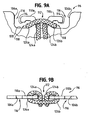
- FIGS. 9A-9B show the configuration of the tie openings 96 in greater detail.
- each of the openings includes a generally rectangular cutout having side edges 106a, 106b and a bottom edge 108.
- First and second, oppositely facing hook members 110a, 110b extend upwardly and outwardly on opposite sides of a central gap 112.
- the outer ends 114 of the hook members are separated from the sidewalls 106a, 106b of the opening by end gaps 116, and are down-turned so as to define first and second, semi-enclosed receiving areas 118.
- Attachment of the net is effected by routing the cords of the attachment loop through the hooks and openings in the manner shown.
- a conventional basketball net 120 has a series of such loops 122 for attachment to the rim, each loop including first and seconds legs 124a, 124b.
- each loop is inserted through an opening so that its two legs 124a, 124b lie in the gap between the hook members. The loop is then bent back upon itself and slipped over the ends of the hook members so that the legs of the loop enter the receiving areas 118, as indicated at 126a, 126b. In this manner, each loop is conveniently and securely attached to the rim assembly.
- Suitable dimensions for an attachment structure in accordance with the embodiment of the invention shown in FIGS. 9A-9B are set forth in the following Table A: DESCRIPTION SIZE cm (inches) Overall height of attachment opening -1,27 (1/2") Overall width of attachment opening -4,12 (1 5/8") Height of hook members -0,95 (3/8") Width of central gap between hook members -0,95 (3/8") Width of hook end gaps -0,47 (3/16") Height of receiving area of the hook members -0,47 (3/16")
- FIGS. 10A-10B shows a tie structure 130 in accordance with another embodiment of the present invention. This is somewhat similar to the structure shown in FIGS. 9A-9B, in that this has a generally rectangular opening with side edges 132a, 132b and a bottom edge 134. In this embodiment, however, the areas for receiving and engaging the cords of the net are defined by right-angle, outwardly facing post members, rather than the hook shaped members shown in FIGS. 9A-9B.
- first and second vertically extending post members 136a, 136b which again define a central gap 138 for receiving the legs 124a, 124b of the attachment loop, with the bottom edge 140 of the gap being raised somewhat above the level of the bottom edge 134 of the main opening.
- First and second horizontal post members 142a, 142b extend outwardly at right angles and in opposite directions from the vertical post members 136a, 136b.
- the outer ends 144a, 144b of the horizontal post members are flared somewhat to help prevent the cords of the attachment loop from sliding thereover, and are spaced inwardly from the edges 132a, 132b and 134 of the opening to define semi-enclosed areas 146a, 146b for receiving and holding the cords, as indicated at 126a, 126b.
- Attachment of the loop is accomplished by inserting this through the central gap and then bending it back over the outwardly extending posts 144a, 144b, in a manner similar to that described above. In the embodiment which is shown in FIGS. 10A-10B, however, and additional turn can be made about the vertical posts 136a, 136b, as indicated at 148a, 148b, making for an even more secure attachment.
- Suitable dimensions for an attachment structure in accordance with the embodiment of the invention which is shown in FIGS. 10A and 10B are set forth in the following Table B: DESCRIPTION SIZE cm (inches) Overall height of attachment opening -1,27 (1/2") Overall width of opening -4,12 (1 5/8") Width of central gap between posts -0,95 (3/8") Height of floor of gap above bottom of opening -0,32 (1/8") Total included width of first and second upright post members -1,74 (11/16") Vertical width of horizontal post members -0,32 (1/8") End gap between horizontal post members and sidewalls of opening -0,47 (3/16") Height of receiving area at horizontal post members -0,47 (3/16")
Landscapes
- Health & Medical Sciences (AREA)
- General Health & Medical Sciences (AREA)
- Physical Education & Sports Medicine (AREA)
- Springs (AREA)
- Devices Affording Protection Of Roads Or Walls For Sound Insulation (AREA)
- Mutual Connection Of Rods And Tubes (AREA)
- Centrifugal Separators (AREA)
Claims (14)
- Nachgiebige Korbballringbaugruppe, die Folgendes umfasst:so dass sich der Torsionsstab (26) als Reaktion auf einen abwärts gerichteten Aufprall auf den Reifenabschnitt elastisch verwindet, um dem Ringelement (12) zu ermöglichen, sich abwärts im Verhältnis zu dem Basiselement (16) zu biegen.ein Basiselement (16),ein Ringelement (12) mit einem Reifenabschnitt, um sich in einer im Allgemeinen horizontalen Ebene zu erstrecken; undmindestens einen Torsionsstab (26), der das Ringelement (12) und das Basiselement (16) in betriebsfähiger Weise miteinander verbindet, wobei der Torsionsstab (26) ein erstes Ende, das an dem Basiselement (16) befestigt ist, und ein zweites Ende, das an dem Ringelement (12) befestigt ist, aufweist, so dass es im Verhältnis zu dem Basiselement (16) drehbar ist;
- Korbballringbaugruppe nach Anspruch 1, wobei das Basiselement Folgendes umfasst:einen Befestigungshalter zur Befestigung an einer im Allgemeinen vertikalen Rückwand.
- Korbballringbaugruppe nach Anspruch 2, wobei der mindestens eine Torsionsstab Folgendes umfasst:einen sich quer erstreckenden Torsionsstab, um sich im Allgemeinen parallel zu der Rückwand zu erstrecken, wobei der sich quer erstreckende Torsionsstab ein erstes Ende, das an dem Befestigungshalter befestigt ist, und ein zweites Ende, das an dem Ringelement befestigt ist, aufweist, so dass der Torsionsstab dem Ringelement ermöglicht, sich abwärts um eine Achse zu biegen, die sich im Allgemeinen parallel zu der Rückwand erstreckt.
- Korbballringbaugruppe nach Anspruch 3, wobei das erste Ende des sich quer erstreckenden Torsionsstabs fest an einem nach vorne vorstehenden Flanschabschnitt des Befestigungshalters befestigt ist und durch eine damit zusammenwirkende Bohrung in einem nach hinten vorstehenden Flanschabschnitt des Ringelements verläuft, und wobei das zweite Ende des sich quer erstreckenden Torsionsstabs fest an einem nach hinten vorstehenden Flanschabschnitt des Ringelements befestigt ist und durch eine damit zusammenwirkende Bohrung in einem nach vorne vorstehenden Flanschabschnitt des Befestigungshalters verläuft.
- Korbballringbaugruppe nach Anspruch 4, wobei jedes Ende des sich quer erstreckenden Torsionsstabs Folgendes umfasst:einen zylindrischen äußeren Abschnitt, um drehbar in die Bohrung in dem Flanschabschnitt einzugreifen, durch die das Ende des Stabs verläuft, so dass das erste Ende des sich quer erstreckenden Torsionsstabs den Flanschabschnitt des Ringelements in Dreheingriff damit stützt und das zweite Ende des Torsionsstabs durch den Flanschabschnitt des Befestigungshalters in Dreheingriff damit gestützt wird.
- Korbballringbaugruppe nach Anspruch 3, die des Weiteren Folgendes umfasst:einen sich längs erstreckenden Torsionsstab, um sich im Allgemeinen senkrecht zu der Rückwand zu erstrecken, wobei der sich längs erstreckende Torsionsstab ein erstes Ende, das an dem Befestigungshalter befestigt ist, und ein zweites Ende, das an dem Ringelement befestigt ist, aufweist, so dass der sich längs erstreckende Torsionsstab der Ringbaugruppe ermöglicht, sich abwärts um eine Achse zu biegen, die sich im Allgemeinen senkrecht zu der Rückwand erstreckt.
- Korbballringbaugruppe nach Anspruch 6, wobei der sich quer erstreckende Torsionsstab an dem zweiten Ende des sich längs erstreckenden Torsionsstabs befestigt ist, so dass der sich quer erstreckende Torsionsstab das Ringelement und das zweite Ende des sich längs erstreckenden Torsionsstabs in betriebsfähiger Weise miteinander verbindet.
- Korbballringbaugruppe nach Anspruch 7, wobei der Befestigungshalter des Weiteren Folgendes umfasst:eine sich vorwärts erstreckende Stützstrebe, die ein äußeres Ende in Dreheingriff mit dem sich längs erstreckenden Torsionsstab aufweist, um den sich längs erstreckenden Torsionsstab gegen abwärts gerichtete Belastungen zu stützen, die von dem Ringelement übertragen werden.
- Korbballringbaugruppe nach Anspruch 1, wobei das Ringelement des Weiteren Folgendes umfasst:einen herabhängenden Flanschabschnitt, der an dem Reifenabschnitt befestigt ist und eine Vielzahl von Durchgangsöffnungen aufweist, die darin gebildet sind, um ein Korbballnetz daran zu befestigen.
- Korbballringbaugruppe nach Anspruch 9, wobei jede der Durchgangsöffnungen Folgendes umfasst:ein erstes und ein zweites Befestigungselement, die sich aufwärts von einer unteren Kante der Durchgangsöffnung erstrecken, wobei die Befestigungselemente voneinander und von einer ersten und einer zweiten Seitenkante der Öffnung beabstandet sind, so dass ein mittlerer Spalt und ein erster und ein zweiter Aufnahmebereich abgegrenzt werden, um eine Befestigungsschlaufe des Netzes darin aufzunehmen und zu halten.
- Korbballringbaugruppe nach Anspruch 10, wobei die Befestigungselemente Folgendes umfassen:ein erstes und ein zweites Hakenelement, die in entgegengesetzten Richtungen auswärts gerichtet sind, um den Spalt und die Aufnahmebereiche abzugrenzen.
- Korbballringbaugruppe nach Anspruch 10, wobei die Befestigungselemente Folgendes umfassen:ein erstes und ein zweites im Allgemeinen vertikales Pfostenelement, die beabstandet sind, um den mittleren Spalt abzugrenzen; undein erstes und ein zweites im Allgemeinen horizontales Pfostenelement, die sich von den vertikalen Pfostenelementen auswärts erstrecken, um die Aufnahmebereiche abzugrenzen.
- Nachgiebige Korbballringbaugruppe, die Folgendes umfasst:so dass der Dreheingriff zwischen den Enden des Torsionsstabs und den Bohrungen in den Flanschabschnitten das Ringelement (12) und den Befestigungshalter für eine Drehbewegung im Verhältnis zueinander stützt und sich der Torsionsstab (26) als Reaktion auf einen abwärts gerichteten Aufprall auf den Reifenabschnitt elastisch verwindet, um dem Ringelement (12) zu ermöglichen, sich abwärts im Verhältnis zu dem Befestigungshalter zu biegen.einen Befestigungshalter (16) zur Befestigung an einer im Allgemeinen vertikalen Rückwand, wobei der Stützhalter einen ersten und einen zweiten parallelen, sich vorwärts erstreckenden Flanschabschnitt (32a, 32b) aufweist;ein Ringelement (12) mit einem Reifenabschnitt, um sich in einer im Allgemeinen horizontalen Ebene zu erstrecken, und einen ersten (34a) und einen zweiten (34b) parallelen, sich rückwärts erstreckenden Flanschabschnitt; undeinen sich quer erstreckenden Torsionsstab (26), der sich im Allgemeinen senkrecht zu den Flanschabschnitten und parallel zu der Rückwand erstreckt, wobei der sich quer erstreckende Torsionsstab (26) ein erstes und ein zweites Ende aufweist, an denen zylindrische Außenseiten gebildet sind, wobei das erste Ende des Torsionsstabs fest an einem nach vorne vorstehenden Flanschabschnitt (32a, 32b) des Befestigungshalters befestigt ist und durch eine damit zusammenwirkende Bohrung in einem nach hinten vorstehenden Flanschabschnitt (34a, 34b) des Ringelements verläuft, so dass die zylindrische Außenseite daran in Dreheingriff damit steht, und das zweite Ende des Torsionsstabs fest an einem sich rückwärts erstreckenden Flanschabschnitt (34a, 34b) des Ringelements befestigt ist und durch eine damit zusammenwirkende Bohrung in einem nach vorne vorstehenden Flanschabschnitt (32a, 32b) des Befestigungshalters verläuft, so dass die zylindrische Außenseite daran in Dreheingriff damit steht;
- Nachgiebige Korbballringbaugruppe, die Folgendes umfasst:so dass sich der sich längs erstreckende (52) und der sich quer erstreckende (54) Torsionsstab als Reaktion auf einen abwärts gerichteten Aufprall, der auf dem Reifenabschnitt empfangen wird, elastisch verwinden, um dem Ringelement (12) zu ermöglichen, sich abwärts um Achsen zu biegen, die sich sowohl parallel als auch senkrecht zu der Rückwand erstrecken.einen Befestigungshalter zur Befestigung an einer im Allgemeinen vertikalen Rückwand;ein Ringelement (12) mit einem Reifenabschnitt, um sich in einer im Allgemeinen horizontalen Ebene zu erstrecken, und einen ersten und einen zweiten im Allgemeinen parallelen, sich rückwärts erstreckenden Flanschabschnitt (34a, 34b);einen ersten sich längs erstreckenden Torsionsstab (52), um sich im Allgemeinen senkrecht zu der Rückwand zu erstrecken, wobei der sich längs erstreckende Torsionsstab (52) ein erstes Ende, das fest an dem Befestigungshalter befestigt ist, und ein zweites Ende, das sich von dem Befestigungshalter vorwärts erstreckt, aufweist, wobei das zweite Ende des sich längs erstreckenden Torsionsstabs (52) eine darauf gebildete zylindrische Außenfläche aufweist;eine Stützstrebe (60) mit einem ersten Ende, das an dem Befestigungshalter befestigt ist, und einem zweiten Ende mit einer Bohrung, in der das zweite Ende des Torsionsstabs (52) in Dreheingriff aufgenommen wird, so dass die Strebe das zweite Ende des sich längs erstreckenden Torsionsstabs gegen abwärts gerichtete Belastungen darauf stützt;ein sich quer erstreckendes Stützrohr (66), das an dem zweiten Ende des sich längs erstreckenden Torsionsstabs (52) befestigt ist, so dass es sich im Wesentlichen in rechten Winkeln dazu erstreckt, wobei das Stützrohr (66) eine im Allgemeinen zylindrische Innenbohrung aufweist; undeinen zweiten sich quer erstreckenden Torsionsstab (54), der in dem Stützrohr (66) befestigt ist, so dass er sich im Allgemeinen parallel zu der Rückwand erstreckt, wobei der sich quer erstreckende Torsionsstab (54) Folgendes aufweist: ein erstes Ende, das fest an einem ersten Ende des Stützrohrs (66) befestigt ist und sich über das erste Ende des Rohrs hinaus erstreckt, so dass eine zylindrische Fläche darauf in Dreheingriff mit einer zusammenwirkenden Bohrung in dem ersten Flanschabschnitt des Ringelements aufgenommen wird, und ein zweites Ende, das fest an dem zweiten Flanschabschnitt des Ringelements befestigt ist und sich in das Stützrohr erstreckt, so dass eine zylindrische Fläche darauf in Dreheingriff mit der Bohrung in dem Rohr aufgenommen wird;
Applications Claiming Priority (2)
| Application Number | Priority Date | Filing Date | Title |
|---|---|---|---|
| US09/854,383 US6503160B2 (en) | 2001-05-11 | 2001-05-11 | Breakaway basketball rim |
| US854383 | 2001-05-11 |
Publications (2)
| Publication Number | Publication Date |
|---|---|
| EP1256362A1 EP1256362A1 (de) | 2002-11-13 |
| EP1256362B1 true EP1256362B1 (de) | 2005-12-21 |
Family
ID=25318543
Family Applications (1)
| Application Number | Title | Priority Date | Filing Date |
|---|---|---|---|
| EP02394053A Expired - Lifetime EP1256362B1 (de) | 2001-05-11 | 2002-05-01 | Basketballkorb mit Torsionsfeder |
Country Status (5)
| Country | Link |
|---|---|
| US (2) | US6503160B2 (de) |
| EP (1) | EP1256362B1 (de) |
| CN (1) | CN1243586C (de) |
| AT (1) | ATE313359T1 (de) |
| DE (1) | DE60208110D1 (de) |
Families Citing this family (15)
| Publication number | Priority date | Publication date | Assignee | Title |
|---|---|---|---|---|
| US6503160B2 (en) * | 2001-05-11 | 2003-01-07 | Porter Athletic Equipment Company | Breakaway basketball rim |
| US7290744B2 (en) * | 2003-04-03 | 2007-11-06 | Baldasari Alan D | Break-away basketball goal system |
| US6848661B2 (en) * | 2003-04-03 | 2005-02-01 | Alan D. Baldasari | Adjustable basketball goal system and mounting method |
| US7331882B1 (en) | 2004-01-08 | 2008-02-19 | Russell Corporation | No tools basketball system and assembly |
| US7175551B1 (en) * | 2004-11-22 | 2007-02-13 | Scott Hamilton | Removable basketball rim assembly |
| US7628718B2 (en) * | 2006-01-17 | 2009-12-08 | Gared Holdings, Llc | Multi-directional break-away goal |
| US7604555B2 (en) * | 2006-02-27 | 2009-10-20 | Lifetime Products, Inc. | Basketball rim assembly |
| US8454460B2 (en) | 2011-03-23 | 2013-06-04 | Gared Holdings, Llc | Breakaway basketball rim assembly |
| US8808118B2 (en) * | 2011-12-22 | 2014-08-19 | Jiao Hsiung Industry Corp. | Basketball hoop |
| CN106880936B (zh) * | 2017-03-28 | 2018-09-11 | 许昌学院 | 一种便捷式篮筐挂网装置 |
| US11000747B2 (en) * | 2018-10-15 | 2021-05-11 | Indian Industries, Inc. | Basketball rim assemblies |
| USD1029941S1 (en) * | 2018-10-25 | 2024-06-04 | Sans End Sports, Llc | Pole having hoops |
| CN111084973B (zh) * | 2020-01-06 | 2021-01-29 | 吉林师范大学 | 一种带有防止卡球装置的篮球架及其使用方法 |
| US11648447B2 (en) | 2020-07-24 | 2023-05-16 | Wm. T. Burnett Ip, Llc | Lacrosse head pocket stringing systems and methods |
| USD1031883S1 (en) * | 2023-07-28 | 2024-06-18 | Chuxuan Chen | Basketball hoop |
Family Cites Families (14)
| Publication number | Priority date | Publication date | Assignee | Title |
|---|---|---|---|---|
| US3462143A (en) | 1966-05-05 | 1969-08-19 | Ronan & Kunzl Inc | Basketball goal with backboard above and separately supported from the goal hoop |
| US4111420A (en) | 1976-07-19 | 1978-09-05 | Frederick Carlson Tyner | Energy absorbing basketball goal/backboard unit |
| US4194734A (en) | 1976-07-19 | 1980-03-25 | Tyner Frederick C | Energy absorbing basketball goal/backboard unit |
| US4365802A (en) | 1976-07-26 | 1982-12-28 | Ehrat Arthur H | Deformation-preventing swingable mount for basketball goals |
| US4534556A (en) | 1977-01-27 | 1985-08-13 | Estlund Paul D | Break-away basketball goal |
| US4483534A (en) * | 1980-08-15 | 1984-11-20 | Saflex Systems | Mounting assembly of controlled resilience for basketball goal hoop |
| US4433839A (en) | 1982-03-25 | 1984-02-28 | John Simonseth | Basketball rim assembly |
| US4723777A (en) | 1984-03-23 | 1988-02-09 | Gared Company | Basketball goal and backboard unit |
| US4738448A (en) | 1987-02-09 | 1988-04-19 | Liester Arvin F | Support assembly for a basketball basket and backboard |
| US5106084A (en) | 1990-01-30 | 1992-04-21 | Schutt Manufacturing Company, Inc. | Breakaway basketball rim |
| US5480139A (en) * | 1991-06-24 | 1996-01-02 | Aubrey J. Owen, Jr. | Basketball practice assembly |
| US5305997A (en) | 1992-01-14 | 1994-04-26 | James Jolly | Basketball rim assembly |
| US6080071A (en) | 1995-11-30 | 2000-06-27 | Basketball Products International, Inc. | Basketball rim and net assembly |
| US6503160B2 (en) * | 2001-05-11 | 2003-01-07 | Porter Athletic Equipment Company | Breakaway basketball rim |
-
2001
- 2001-05-11 US US09/854,383 patent/US6503160B2/en not_active Expired - Fee Related
-
2002
- 2002-05-01 DE DE60208110T patent/DE60208110D1/de not_active Expired - Lifetime
- 2002-05-01 AT AT02394053T patent/ATE313359T1/de not_active IP Right Cessation
- 2002-05-01 EP EP02394053A patent/EP1256362B1/de not_active Expired - Lifetime
- 2002-05-10 CN CNB021413606A patent/CN1243586C/zh not_active Expired - Fee Related
- 2002-12-31 US US10/334,507 patent/US6935972B2/en not_active Expired - Lifetime
Also Published As
| Publication number | Publication date |
|---|---|
| US6503160B2 (en) | 2003-01-07 |
| US6935972B2 (en) | 2005-08-30 |
| CN1386556A (zh) | 2002-12-25 |
| CN1243586C (zh) | 2006-03-01 |
| US20020187865A1 (en) | 2002-12-12 |
| EP1256362A1 (de) | 2002-11-13 |
| ATE313359T1 (de) | 2006-01-15 |
| US20030148834A1 (en) | 2003-08-07 |
| DE60208110D1 (de) | 2006-01-26 |
Similar Documents
| Publication | Publication Date | Title |
|---|---|---|
| EP1256362B1 (de) | Basketballkorb mit Torsionsfeder | |
| US5586759A (en) | Basketball goal unit | |
| JP5129251B2 (ja) | 衝撃吸収システムを有するセレクタ式ダンベル | |
| US4438923A (en) | Shock-absorbing basketball goal unit | |
| US4395040A (en) | Adjustable basketball goal | |
| US7113145B1 (en) | Antenna mounting bracket assembly | |
| US7604555B2 (en) | Basketball rim assembly | |
| US5653669A (en) | Universal gym with uniform resistances | |
| EP3525895B1 (de) | Rohrgestellstangen zur verwendung mit einer übungsmaschine | |
| US20140066259A1 (en) | Trampolines | |
| US6626410B2 (en) | Portable highway sign stand | |
| US4575079A (en) | Articulated resiliently-biased mounted means for basketball hoop | |
| US4955533A (en) | Support and protective structure for a mail box | |
| US4119311A (en) | Combination trampoline and rebounding device with detachable support means | |
| AU2004201140B2 (en) | Basketball rim assembly | |
| US5305997A (en) | Basketball rim assembly | |
| US7306530B2 (en) | Adjustable height basketball goal | |
| US6955615B1 (en) | Pitcher screen | |
| US6334822B1 (en) | Deflectable basketball hoop | |
| US6824481B1 (en) | Impact transmitting strike plate for a basketball goal assembly | |
| US4709540A (en) | Mowing device | |
| US5797810A (en) | Batting practice device | |
| US5056784A (en) | Athletic swing training device | |
| CN219595792U (zh) | 一种角度可调式回球器 | |
| KR100414390B1 (ko) | 낙하물 방지틀 지지장치 |
Legal Events
| Date | Code | Title | Description |
|---|---|---|---|
| PUAI | Public reference made under article 153(3) epc to a published international application that has entered the european phase |
Free format text: ORIGINAL CODE: 0009012 |
|
| AK | Designated contracting states |
Kind code of ref document: A1 Designated state(s): AT BE CH CY DE DK ES FI FR GB GR IE IT LI LU MC NL PT SE TR |
|
| AX | Request for extension of the european patent |
Free format text: AL;LT;LV;MK;RO;SI |
|
| 17P | Request for examination filed |
Effective date: 20021119 |
|
| AKX | Designation fees paid |
Designated state(s): AT BE CH CY DE DK ES FI FR GB GR IE IT LI LU MC NL PT SE TR |
|
| GRAP | Despatch of communication of intention to grant a patent |
Free format text: ORIGINAL CODE: EPIDOSNIGR1 |
|
| GRAS | Grant fee paid |
Free format text: ORIGINAL CODE: EPIDOSNIGR3 |
|
| GRAA | (expected) grant |
Free format text: ORIGINAL CODE: 0009210 |
|
| AK | Designated contracting states |
Kind code of ref document: B1 Designated state(s): AT BE CH CY DE DK ES FI FR GB GR IE IT LI LU MC NL PT SE TR |
|
| PG25 | Lapsed in a contracting state [announced via postgrant information from national office to epo] |
Ref country code: IT Free format text: LAPSE BECAUSE OF FAILURE TO SUBMIT A TRANSLATION OF THE DESCRIPTION OR TO PAY THE FEE WITHIN THE PRESCRIBED TIME-LIMIT;WARNING: LAPSES OF ITALIAN PATENTS WITH EFFECTIVE DATE BEFORE 2007 MAY HAVE OCCURRED AT ANY TIME BEFORE 2007. THE CORRECT EFFECTIVE DATE MAY BE DIFFERENT FROM THE ONE RECORDED. Effective date: 20051221 Ref country code: LI Free format text: LAPSE BECAUSE OF FAILURE TO SUBMIT A TRANSLATION OF THE DESCRIPTION OR TO PAY THE FEE WITHIN THE PRESCRIBED TIME-LIMIT Effective date: 20051221 Ref country code: CH Free format text: LAPSE BECAUSE OF FAILURE TO SUBMIT A TRANSLATION OF THE DESCRIPTION OR TO PAY THE FEE WITHIN THE PRESCRIBED TIME-LIMIT Effective date: 20051221 Ref country code: BE Free format text: LAPSE BECAUSE OF FAILURE TO SUBMIT A TRANSLATION OF THE DESCRIPTION OR TO PAY THE FEE WITHIN THE PRESCRIBED TIME-LIMIT Effective date: 20051221 Ref country code: AT Free format text: LAPSE BECAUSE OF FAILURE TO SUBMIT A TRANSLATION OF THE DESCRIPTION OR TO PAY THE FEE WITHIN THE PRESCRIBED TIME-LIMIT Effective date: 20051221 Ref country code: FI Free format text: LAPSE BECAUSE OF FAILURE TO SUBMIT A TRANSLATION OF THE DESCRIPTION OR TO PAY THE FEE WITHIN THE PRESCRIBED TIME-LIMIT Effective date: 20051221 Ref country code: NL Free format text: LAPSE BECAUSE OF FAILURE TO SUBMIT A TRANSLATION OF THE DESCRIPTION OR TO PAY THE FEE WITHIN THE PRESCRIBED TIME-LIMIT Effective date: 20051221 |
|
| REG | Reference to a national code |
Ref country code: GB Ref legal event code: FG4D |
|
| REG | Reference to a national code |
Ref country code: CH Ref legal event code: EP |
|
| REG | Reference to a national code |
Ref country code: IE Ref legal event code: FG4D |
|
| REF | Corresponds to: |
Ref document number: 60208110 Country of ref document: DE Date of ref document: 20060126 Kind code of ref document: P |
|
| PG25 | Lapsed in a contracting state [announced via postgrant information from national office to epo] |
Ref country code: GR Free format text: LAPSE BECAUSE OF FAILURE TO SUBMIT A TRANSLATION OF THE DESCRIPTION OR TO PAY THE FEE WITHIN THE PRESCRIBED TIME-LIMIT Effective date: 20060321 Ref country code: SE Free format text: LAPSE BECAUSE OF FAILURE TO SUBMIT A TRANSLATION OF THE DESCRIPTION OR TO PAY THE FEE WITHIN THE PRESCRIBED TIME-LIMIT Effective date: 20060321 Ref country code: DK Free format text: LAPSE BECAUSE OF FAILURE TO SUBMIT A TRANSLATION OF THE DESCRIPTION OR TO PAY THE FEE WITHIN THE PRESCRIBED TIME-LIMIT Effective date: 20060321 |
|
| PG25 | Lapsed in a contracting state [announced via postgrant information from national office to epo] |
Ref country code: DE Free format text: LAPSE BECAUSE OF FAILURE TO SUBMIT A TRANSLATION OF THE DESCRIPTION OR TO PAY THE FEE WITHIN THE PRESCRIBED TIME-LIMIT Effective date: 20060322 |
|
| PG25 | Lapsed in a contracting state [announced via postgrant information from national office to epo] |
Ref country code: ES Free format text: LAPSE BECAUSE OF FAILURE TO SUBMIT A TRANSLATION OF THE DESCRIPTION OR TO PAY THE FEE WITHIN THE PRESCRIBED TIME-LIMIT Effective date: 20060401 |
|
| PG25 | Lapsed in a contracting state [announced via postgrant information from national office to epo] |
Ref country code: IE Free format text: LAPSE BECAUSE OF NON-PAYMENT OF DUE FEES Effective date: 20060501 Ref country code: GB Free format text: LAPSE BECAUSE OF NON-PAYMENT OF DUE FEES Effective date: 20060501 |
|
| PG25 | Lapsed in a contracting state [announced via postgrant information from national office to epo] |
Ref country code: PT Free format text: LAPSE BECAUSE OF FAILURE TO SUBMIT A TRANSLATION OF THE DESCRIPTION OR TO PAY THE FEE WITHIN THE PRESCRIBED TIME-LIMIT Effective date: 20060522 |
|
| PG25 | Lapsed in a contracting state [announced via postgrant information from national office to epo] |
Ref country code: MC Free format text: LAPSE BECAUSE OF NON-PAYMENT OF DUE FEES Effective date: 20060531 |
|
| NLV1 | Nl: lapsed or annulled due to failure to fulfill the requirements of art. 29p and 29m of the patents act | ||
| REG | Reference to a national code |
Ref country code: CH Ref legal event code: PL |
|
| PLBE | No opposition filed within time limit |
Free format text: ORIGINAL CODE: 0009261 |
|
| STAA | Information on the status of an ep patent application or granted ep patent |
Free format text: STATUS: NO OPPOSITION FILED WITHIN TIME LIMIT |
|
| 26N | No opposition filed |
Effective date: 20060922 |
|
| GBPC | Gb: european patent ceased through non-payment of renewal fee |
Effective date: 20060501 |
|
| EN | Fr: translation not filed | ||
| REG | Reference to a national code |
Ref country code: IE Ref legal event code: MM4A |
|
| PG25 | Lapsed in a contracting state [announced via postgrant information from national office to epo] |
Ref country code: FR Free format text: LAPSE BECAUSE OF FAILURE TO SUBMIT A TRANSLATION OF THE DESCRIPTION OR TO PAY THE FEE WITHIN THE PRESCRIBED TIME-LIMIT Effective date: 20070209 |
|
| PG25 | Lapsed in a contracting state [announced via postgrant information from national office to epo] |
Ref country code: LU Free format text: LAPSE BECAUSE OF NON-PAYMENT OF DUE FEES Effective date: 20060501 Ref country code: TR Free format text: LAPSE BECAUSE OF FAILURE TO SUBMIT A TRANSLATION OF THE DESCRIPTION OR TO PAY THE FEE WITHIN THE PRESCRIBED TIME-LIMIT Effective date: 20051221 |
|
| PG25 | Lapsed in a contracting state [announced via postgrant information from national office to epo] |
Ref country code: FR Free format text: LAPSE BECAUSE OF FAILURE TO SUBMIT A TRANSLATION OF THE DESCRIPTION OR TO PAY THE FEE WITHIN THE PRESCRIBED TIME-LIMIT Effective date: 20051221 Ref country code: CY Free format text: LAPSE BECAUSE OF FAILURE TO SUBMIT A TRANSLATION OF THE DESCRIPTION OR TO PAY THE FEE WITHIN THE PRESCRIBED TIME-LIMIT Effective date: 20051221 |