EP1255698B1 - Water treatment unit - Google Patents
Water treatment unit Download PDFInfo
- Publication number
- EP1255698B1 EP1255698B1 EP20010915172 EP01915172A EP1255698B1 EP 1255698 B1 EP1255698 B1 EP 1255698B1 EP 20010915172 EP20010915172 EP 20010915172 EP 01915172 A EP01915172 A EP 01915172A EP 1255698 B1 EP1255698 B1 EP 1255698B1
- Authority
- EP
- European Patent Office
- Prior art keywords
- reactor
- filter
- water
- support body
- nozzle
- Prior art date
- Legal status (The legal status is an assumption and is not a legal conclusion. Google has not performed a legal analysis and makes no representation as to the accuracy of the status listed.)
- Expired - Lifetime
Links
Images


Classifications
-
- C—CHEMISTRY; METALLURGY
- C02—TREATMENT OF WATER, WASTE WATER, SEWAGE, OR SLUDGE
- C02F—TREATMENT OF WATER, WASTE WATER, SEWAGE, OR SLUDGE
- C02F1/00—Treatment of water, waste water, or sewage
- C02F1/44—Treatment of water, waste water, or sewage by dialysis, osmosis or reverse osmosis
- C02F1/444—Treatment of water, waste water, or sewage by dialysis, osmosis or reverse osmosis by ultrafiltration or microfiltration
-
- B—PERFORMING OPERATIONS; TRANSPORTING
- B01—PHYSICAL OR CHEMICAL PROCESSES OR APPARATUS IN GENERAL
- B01D—SEPARATION
- B01D33/00—Filters with filtering elements which move during the filtering operation
- B01D33/15—Filters with filtering elements which move during the filtering operation with rotary plane filtering surfaces
- B01D33/21—Filters with filtering elements which move during the filtering operation with rotary plane filtering surfaces with hollow filtering discs transversely mounted on a hollow rotary shaft
-
- B—PERFORMING OPERATIONS; TRANSPORTING
- B01—PHYSICAL OR CHEMICAL PROCESSES OR APPARATUS IN GENERAL
- B01D—SEPARATION
- B01D33/00—Filters with filtering elements which move during the filtering operation
- B01D33/58—Handling the filter cake in the filter for purposes other than for regenerating the filter cake remaining on the filtering element
- B01D33/68—Retarding cake deposition on the filter during the filtration period, e.g. using stirrers
-
- B—PERFORMING OPERATIONS; TRANSPORTING
- B01—PHYSICAL OR CHEMICAL PROCESSES OR APPARATUS IN GENERAL
- B01D—SEPARATION
- B01D33/00—Filters with filtering elements which move during the filtering operation
- B01D33/70—Filters with filtering elements which move during the filtering operation having feed or discharge devices
- B01D33/72—Filters with filtering elements which move during the filtering operation having feed or discharge devices for feeding
- B01D33/727—Filters with filtering elements which move during the filtering operation having feed or discharge devices for feeding provoking a tangential stream
-
- B—PERFORMING OPERATIONS; TRANSPORTING
- B01—PHYSICAL OR CHEMICAL PROCESSES OR APPARATUS IN GENERAL
- B01D—SEPARATION
- B01D61/00—Processes of separation using semi-permeable membranes, e.g. dialysis, osmosis or ultrafiltration; Apparatus, accessories or auxiliary operations specially adapted therefor
- B01D61/14—Ultrafiltration; Microfiltration
- B01D61/20—Accessories; Auxiliary operations
-
- B—PERFORMING OPERATIONS; TRANSPORTING
- B01—PHYSICAL OR CHEMICAL PROCESSES OR APPARATUS IN GENERAL
- B01D—SEPARATION
- B01D63/00—Apparatus in general for separation processes using semi-permeable membranes
- B01D63/16—Rotary, reciprocated or vibrated modules
-
- B—PERFORMING OPERATIONS; TRANSPORTING
- B01—PHYSICAL OR CHEMICAL PROCESSES OR APPARATUS IN GENERAL
- B01D—SEPARATION
- B01D65/00—Accessories or auxiliary operations, in general, for separation processes or apparatus using semi-permeable membranes
- B01D65/08—Prevention of membrane fouling or of concentration polarisation
-
- B—PERFORMING OPERATIONS; TRANSPORTING
- B01—PHYSICAL OR CHEMICAL PROCESSES OR APPARATUS IN GENERAL
- B01D—SEPARATION
- B01D2315/00—Details relating to the membrane module operation
- B01D2315/06—Submerged-type; Immersion type
-
- B—PERFORMING OPERATIONS; TRANSPORTING
- B01—PHYSICAL OR CHEMICAL PROCESSES OR APPARATUS IN GENERAL
- B01D—SEPARATION
- B01D2321/00—Details relating to membrane cleaning, regeneration, sterilization or to the prevention of fouling
- B01D2321/18—Use of gases
- B01D2321/185—Aeration
-
- B—PERFORMING OPERATIONS; TRANSPORTING
- B01—PHYSICAL OR CHEMICAL PROCESSES OR APPARATUS IN GENERAL
- B01D—SEPARATION
- B01D2321/00—Details relating to membrane cleaning, regeneration, sterilization or to the prevention of fouling
- B01D2321/20—By influencing the flow
- B01D2321/2008—By influencing the flow statically
- B01D2321/2025—Tangential inlet
-
- B—PERFORMING OPERATIONS; TRANSPORTING
- B01—PHYSICAL OR CHEMICAL PROCESSES OR APPARATUS IN GENERAL
- B01D—SEPARATION
- B01D2321/00—Details relating to membrane cleaning, regeneration, sterilization or to the prevention of fouling
- B01D2321/20—By influencing the flow
- B01D2321/2033—By influencing the flow dynamically
- B01D2321/2041—Mixers; Agitators
-
- C—CHEMISTRY; METALLURGY
- C02—TREATMENT OF WATER, WASTE WATER, SEWAGE, OR SLUDGE
- C02F—TREATMENT OF WATER, WASTE WATER, SEWAGE, OR SLUDGE
- C02F2301/00—General aspects of water treatment
- C02F2301/06—Pressure conditions
- C02F2301/066—Overpressure, high pressure
-
- C—CHEMISTRY; METALLURGY
- C02—TREATMENT OF WATER, WASTE WATER, SEWAGE, OR SLUDGE
- C02F—TREATMENT OF WATER, WASTE WATER, SEWAGE, OR SLUDGE
- C02F2303/00—Specific treatment goals
- C02F2303/18—Removal of treatment agents after treatment
-
- C—CHEMISTRY; METALLURGY
- C02—TREATMENT OF WATER, WASTE WATER, SEWAGE, OR SLUDGE
- C02F—TREATMENT OF WATER, WASTE WATER, SEWAGE, OR SLUDGE
- C02F3/00—Biological treatment of water, waste water, or sewage
- C02F3/02—Aerobic processes
- C02F3/06—Aerobic processes using submerged filters
-
- C—CHEMISTRY; METALLURGY
- C02—TREATMENT OF WATER, WASTE WATER, SEWAGE, OR SLUDGE
- C02F—TREATMENT OF WATER, WASTE WATER, SEWAGE, OR SLUDGE
- C02F3/00—Biological treatment of water, waste water, or sewage
- C02F3/02—Aerobic processes
- C02F3/12—Activated sludge processes
-
- C—CHEMISTRY; METALLURGY
- C02—TREATMENT OF WATER, WASTE WATER, SEWAGE, OR SLUDGE
- C02F—TREATMENT OF WATER, WASTE WATER, SEWAGE, OR SLUDGE
- C02F3/00—Biological treatment of water, waste water, or sewage
- C02F3/28—Anaerobic digestion processes
- C02F3/286—Anaerobic digestion processes including two or more steps
-
- Y—GENERAL TAGGING OF NEW TECHNOLOGICAL DEVELOPMENTS; GENERAL TAGGING OF CROSS-SECTIONAL TECHNOLOGIES SPANNING OVER SEVERAL SECTIONS OF THE IPC; TECHNICAL SUBJECTS COVERED BY FORMER USPC CROSS-REFERENCE ART COLLECTIONS [XRACs] AND DIGESTS
- Y02—TECHNOLOGIES OR APPLICATIONS FOR MITIGATION OR ADAPTATION AGAINST CLIMATE CHANGE
- Y02W—CLIMATE CHANGE MITIGATION TECHNOLOGIES RELATED TO WASTEWATER TREATMENT OR WASTE MANAGEMENT
- Y02W10/00—Technologies for wastewater treatment
- Y02W10/10—Biological treatment of water, waste water, or sewage
Definitions
- the present invention relates to a device for the treatment of water, in particular waste water and drinking water and a method for carrying out a treatment of water using this device.
- Water treatment involves the treatment of water with the aim of adapting its nature to the intended use as well as to specific requirements.
- Processes for treating drinking water include, for example, flocculation, filtration, aeration, de-ironing, demanganization, deacidification, disinfection, phosphating, denitrification and fluoridation processes.
- wastewater is modified water (dirty water) in its natural composition, as well as the less polluted rainwater and meltwater draining from built-up areas, the type and concentration of contaminants being highly dependent on the source of the wastewater are dependent.
- Wastewater treatment uses physical, chemical and / or biological processes, which often have to be used together to achieve a high degree of cleaning efficiency. In chemical processes, pollutants become more easily removable or into harmless reaction products transformed. For example, reactions that cause oxidation, reduction or the formation of sparingly soluble compounds are used.
- aerobic wastewater treatment In biological processes, the organic substances are metabolized by microorganisms and microorganisms with new formation of biomass to harmless compounds. Basically, a distinction is made between aerobic and anaerobic wastewater treatment.
- the aim of aerobic wastewater treatment is to reduce oxygen-depleting substances as far as possible, whereby organic substances are reduced by the organisms involved in the decomposition with formation of carbon dioxide, water, nitrates and sulfates.
- the basic requirement for aerobic systems is adequate ventilation with air (or oxygen-enriched air or pure oxygen).
- Anaerobic wastewater treatment ie the biological degradation of organic substances with the exclusion of oxygen, is also gaining in importance.
- Anaerobic digestion is fermentation processes (for example, alcohol, acetic acid, lactic acid, acetone-butanol fermentation, etc.).
- the wastewater contents are concentrated according to their physical properties such as particle size, density and rate of descent according to different methods.
- solid auxiliaries for example adsorption, filtration, ion exchange
- liquid auxiliaries extraction
- gaseous auxiliaries fractional auxiliaries
- thermal energy distillation, evaporation
- gravity settling, floating
- Membrane separation techniques and devices are used in many scientific and industrial applications except water treatment. Separation steps in membrane separation technology can be divided into the classes of micro-, ultra- and nanofiltration as well as reverse osmosis according to the separation limits. By means of these methods, particle sizes of up to 5 nm can be separated off. The solids are retained by the membrane and at least concentrate directly on the membrane while the filtered liquid passes through the membrane. A so-called concentration polarization causes a cover layer structure, which is also known as membrane fouling, which can be structurally influenced by different modes of operation. The classical modes of operation have become the dead-end and cross-flow filtration.
- the typical specific energy requirement for cross-flow ultrafiltration is, for example, 3 to 7 kWh / m 3 with filtrate flows of about 100 to 150 l / m 2 h and a transmembrane pressure of 3 to 5 bar.
- comparable values of about 0.1 to 0.5 kWh / m 3 result at filtrate flows of about 50 to 80 l / m 2 h for a transmembrane pressure of about 0.5 to 2 bar.
- the dead-end filtration results in even higher investment costs but lower operating costs.
- dipping systems are used, for example, in aeration tanks of sewage treatment plants, so that a certain reduction of the surface layer formation is possible by the movement of the liquid phase due to the fumigation occurring there. Nevertheless, a significant reduction of the filtrate flow over time due to uncontrolled surface layer formation is a major obstacle to the economical use of such dipping systems in sewage treatment plants.
- a filtration module which consists of cassettes, which include disk-shaped flat membranes, in which the feed can flow on all sides from the outside through the membranes.
- the permeate is discharged in the middle through a central manifold.
- this filter When operated as a cross-flow filter, this filter causes the problems described above, that is, the energy costs are very high. In particular at high overflow velocities and front feed of the feed solution, mechanical damage of the individual membrane disks may occur.
- JP 05 076899-A a filter device is described, which has a plurality of membrane discs which are rotatably connected to a hollow, rotatable support body: the emerging from the bottom region of a reactor liquid is pressed by a pump in the filter device and the concentrate is in the returned to the top of the reactor.
- the technical problem underlying the present invention is thus to provide an economical method and a cost-effective device for water treatment, in particular for the filtration of high volume flows with little added value, in particular for cleaning municipal and industrial wastewater or drinking water obtained from surface waters.
- the present invention solves the technical problem on which it is based by providing a device for treating water, in particular waste water or process water, comprising a reactor and a filter device in fluid communication with the reactor, the filter device being arranged below the reactor bottom and at least one with a hollow rotatable support body rotatably connected filter element, the interior of which is in fluid communication with the interior of the support body in such a way that the filtrate from the interior of the at least one filter element into the interior of the support body and can be removed from there.
- the inventively provided arrangement of the filter device below the reactor bottom, outside the reactor allows the energetically advantageous exploitation of existing in many technical systems hydrostatic and / or hydrodynamic pressures to produce a transmembrane pressure gradient across the filter element.
- filter device in a preferred embodiment as a module with stacked filter discs, which may be made of both inorganic and organic material, made possible for the first time the economical use of membrane separation technology for the filtration of high volume flows at low Value creation, for example in the purification of liquids or suspensions, in particular municipal or industrial wastewater or in the production of drinking water from surface waters.
- filter device that is, the filter element arranged on the support body, in a preferably cylindrical housing and to position it below the reactor.
- filter device and reactor are to be connected to each other via inlet and outlet connections, for example pipes or hoses.
- the housing fills with the suspension to be filtered, wherein the support body is set in rotation about its longitudinal axis, for example by means of a motor.
- Filtrate is drawn in through the at least one filter disk arranged non-rotatably on the support body and withdrawn from the apparatus according to the invention through the hollow shaft which is in flow connection with the filter disk.
- the hydrostatic and hydrodynamic pressure present in many plants which are suitable for the present device is utilized as transmembrane pressure gradient.
- Modern wastewater treatment plants have, for example, aeration reactors of up to 20 m in height, whereby a transmembrane pressure gradient due to the hydrostatic pressure of almost 2 bar is possible.
- aerobically operating reactors frequently disperse the gas phase introduced for aeration by means of liquid jets, for example at speeds of up to 20 m / s.
- the device according to the invention therefore has several Advantages. Compared to cross-flow systems, significantly lower specific energy costs result and there is no danger of blockage for the filter elements. Compared with plate modules or Zee-Weed modules, which are installed in a wastewater reactor, there is the advantage that the oxygen supply aerobic microorganisms is decoupled from the filtration in the apparatus according to the invention, since the air supply and the liquid circulation for the gas dispersion largely independent of the desired filtration performance can be adjusted. The control of the top layer structure is achieved rather by the rotation of the disc filter and can thus be adjusted independently of the supply of aerobic microorganisms.
- the cover layer structure can be further influenced.
- the transmembrane pressure is generated by the hydrostatic pressure necessarily present in the wastewater reactors and, in addition, by the hydrodynamic pressure necessary for gas dispersion by means of a liquid jet.
- no appreciable additional pressure drop in the membrane module of the rotary disk filter is required because the flow through the module is not required to produce high overflow speeds, but only the hydrodynamic pressure is utilized and therefore the free flow cross section is sufficiently large can be selected so that virtually no additional pressure drop and thus energy requirements. This results significantly Lower specific energy costs than in cross-flow filtration.
- the interior of the support body via one or more openings, tubes, channels, lines, holes, slots, porous areas or the like with the interior of the support body in connection so that a liquid flow from the interior of the filter element can be made in the support body interior and thus a fluid connection is provided.
- the hollow support body is a hollow shaft, for example a tubular hollow shaft.
- it can be provided to carry out the filter element as a filter disk.
- the filter disk can be designed, for example, as a membrane-comprising or membrane-coated hollow body or hollow frame. According to the invention, it is possible to use, for example, technical membranes customarily used in membrane separation technology, for example polymer membranes, membrane filters, ultrafiltration membranes or microfiltration membranes.
- the invention thus also relates in a further embodiment to an aforementioned water treatment device with reactor and filter device, wherein the hollow support body is located in a housing, preferably rotatably mounted in a housing, in particular a cylindrical housing.
- a housing may, for example, have an inlet from the reactor and a drain, wherein liquid to be filtered can be introduced into the housing through the inlet and the separated solids can be removed by a drain.
- the inflow of the suspension to be filtered is advantageously tangential.
- the solids also referred to as concentrate, can be withdrawn via a tangential discharge on the cylinder wall or on the lower end wall. The filtrate leaves the housing through the hollow support body.
- the invention provides in a further preferred embodiment, that in the housing of the filter device internals for influencing the flow can be provided, for example, current breaker.
- the filter elements have passage openings for receiving the support body.
- the filter elements are arranged spaced apart in a preferred embodiment on the support body, wherein in a further preferred embodiment, the longitudinal axis of the support body perpendicular to the upper and lower sides, ie base surfaces, the filter element designed as a filter disk is.
- the invention thus provides that the at least one filter disc is rotatably mounted on a rotatable hollow shaft, that the filtrate can be deducted by this.
- the hollow shaft may be integrally formed and pass through the at least one filter disc through a, in a preferred embodiment centrally disposed in the latter passage opening, wherein at least one opening in the region of the hollow shaft is provided, which surrounds the filter disc with its inner circumferential surface, so that liquid from the filter disk can get into the interior of the hollow shaft.
- the support body in particular the hollow shaft is formed in several pieces from different, for example tubular, hollow sections, wherein the different sections of the support body separated by these filter elements, in particular filter discs, and as it were to be filtered Zu practicesswashkeit are liquid-tight connected by this.
- a fluid connection for example, an opening between the interior of the support body and the filter element is provided. The penetrating into the interior of the filter discs filtrate can thus pass from the interior of the filter disc into the interior of the hollow shaft and be deducted from this.
- the invention further provides that the filter device used according to the invention is designed in a modular design.
- the filter device used according to the invention can be used in both aerobic and anaerobic systems, for example wastewater treatment or water treatment systems.
- the filter device can be installed, for example, in the activation stage of a sewage treatment plant and represents a modern system for biomass retention and thus for the concentration of biomass.
- the filter device can of course also be used in the separation of the feed to sewage treatment plants after or instead of the primary treatment.
- the feed is separated into a carbon-rich concentrate, which can be anaerobically converted to biogas, and a low-carbon filtrate, which can be aerobically reacted, for example, in high-performance wastewater reactors.
- the device according to the invention can thus be embodied as a device which has means for introducing air or gas and permits aerobic operating guides.
- the device according to the invention can also be embodied as an air-tight or gas-tight device or as a device equipped with an air-tight or gas-tight reactor or else it can be an anaerobic operation-permitting device by other measures.
- Such a device allows low-cost filtration in the course of bioprocesses that do not require atmospheric oxygen such as denitrification or even oxygen such as lactic acid, ethanol or acetone-butanol fermentation.
- the invention also solves the problem on which it is based by providing a process for the treatment of water, in particular wastewater and drinking water, in which a separation of a filtrate of solids from the water to be purified and wherein one of the devices according to the invention is used.
- the invention accordingly relates to a method for obtaining drinking water or for the purification of waste water, according to which a filter device to be used according to the invention, ie a hollow and rotatable, for example in a housing, mounted hollow body rotatable with at least one filter element, substantially only under influence hydrostatic and hydrodynamic pressure is exposed to the water to be purified and rotated in a rotational movement to produce an overflow velocity and withdrawn through the at least one filter element into the interior of the hollow support body inflowing filtrate through the hollow support body and thereby separated from the concentrate.
- a filter device to be used according to the invention ie a hollow and rotatable, for example in a housing, mounted hollow body rotatable with at least one filter element, substantially only under influence hydrostatic and hydrodynamic pressure is exposed to the water to be purified and rotated in a rotational movement to produce an overflow velocity and withdrawn through the at least one filter element into the interior of the hollow support body inflowing filtrate through the hollow support body and thereby separated from
- the reactor to be purified produces Liquid or suspension a hydrostatic pressure, which is arranged on a filter device according to the invention used in the lower region of the reactor, for example in the region of the reactor bottom or, if outside, in particular below the reactor, and then connected via connecting means to the reactor, acts such that transmembrane pressure gradient is generated via the filter element, which allows in an energetically favorable manner, the filtration of the liquid or suspension to be filtered.
- the filter device arranged in a housing is arranged below the bottom of an aerobic working reactor and a nozzle, in particular a two-fluid nozzle, is arranged in the reactor bottom and the air and concentrate fed from the filter device injected into the reactor and thereby additionally to the hydrostatic pressure acting on the filter device generates, namely a hydrodynamic pressure.
- the invention relates in a further embodiment to an aforementioned method, wherein the water to be treated is feed water to a sewage treatment plant, which is supplied to an aforementioned apparatus for the treatment of water, in which the reactor is designed as the feed water containing feed basin and exiting according to the above method Filtrate after separation from the concentrate is fed to a feed tank downstream of the activation reactor, in a preferred embodiment part of another device according to the present invention. Accordingly, in such a process for the treatment of wastewater two devices according to the invention are connected in series, each having a reactor and a filter device.
- the liquid / suspension to be filtered out of the reactor via a pump into the filter device.
- the filtrate is withdrawn via the hollow shaft and the concentrate optionally together with air through a nozzle, in particular a two-fluid nozzle, re-introduced into the reactor, for example, in a wastewater reactor desired high cell densities of microorganisms can be achieved.
- the liquid / suspension to be filtered out of the reactor into the filter device preferably arranged in a housing, the filtrate being withdrawn from the hollow shaft and the concentrate being pumped to a nozzle preferably arranged in the reactor bottom , in particular a two-fluid nozzle, is passed, the the concentrate is introduced into the reactor together with air.
- the concentrate is not returned to the reactor again.
- the suspension to be filtered from the reactor can be supplied via a pump to the filter device, which is preferably arranged in a housing.
- the concentrate is discharged, for example in a digestion system and the filtrate is discharged through the hollow shaft.
- Some of the suspension / liquid brought in via the pump is not fed into the filter device, but rather directly to a nozzle, preferably arranged in the bottom of the reactor, which optionally together with air recycles the suspension back into the reactor. In this way, it is possible to set a specific cell density in the reactor in a controlled manner.
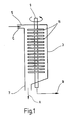
- FIG. 1 shows a filter device 1 embodied as a membrane module with a cylindrical housing 3 which has a liquid or suspension (C) containing a tangentially arranged inlet 5 for the solids to be filtered and a discharge opening 7 for the separated solids, ie the concentrate (FIG. A).
- a hollow shaft 9 is rotatably mounted, which carries a plurality of rotatably connected with her filter discs 11.
- the filtrate (B) is discharged from the hollow shaft 9.
- the tubular hollow shaft 9 is integrally formed and passes through the respective one, not shown, central passage openings having filter discs 11th
- the operation of the filter device 1 is as follows:
- the membrane module 1 used according to the invention together with an aerobic reactor not shown here is, for example, mounted in the liquid circuit in front of the nozzle, not shown, in the area near the bottom to an activation reactor, so that the flow of the pump through the inlet opening 5 into the housing 3 can occur.
- the concentrate supplied through the outlet port 7 of the nozzle is accelerated in the nozzle to a high speed, whereby a liquid jet arises in the reactor for gas dispersion.
- the resulting hydrodynamic pressure is used together with the pressure on the membrane module from the filling of the reactor resulting hydrostatic pressure to produce a transmembrane pressure gradient and leads to the filtration of the liquid fed.
- the necessary for the prevention of the top layer structure overflow velocity is effected by a rotation of the support body and thus the filter elements.
- FIG. 2 schematically shows a device 100 according to the invention for the treatment of water comprising an aerobic reactor 40 and a.
- Filter Device 1 The reactor 40 is a wastewater reactor and designed as a loop reactor with an inner flow tube 50. The content of the reactor is circulated around the flow conduit 50, resulting in intensive mixing. Shown is also the inlet 110 and the outlet 120 of the reactor as well as the bottom 30 of the reactor 40.
- the reactor has a filling height H, with the highest possible filling level is preferred.
- the circulation of the circulating flow present in the reactor 40 is effected by a liquid-air jet irradiated at the reactor bottom 30.
- a liquid-air jet irradiated at the reactor bottom 30 For this purpose, is sucked from a pump 70, which is located outside of the reactor 40, 30 at the bottom of waste water and, via the lines 35 and 37 of a arranged in the reactor bottom 30 nozzle 60, in which the waste water is injected into the reactor 40 at high speed , whereby together with the sucked air 80 an intensive gas dispersion is achieved.
- a membrane module 1 is under the hydrostatic pressure of the liquid column of the wastewater reactor 40 and under the hydrodynamic pressure generated by the pump 70 by means of the nozzle 60.
- Both pressures produce a transmembrane pressure gradient, which allows the filtration of the wastewater in a cost effective manner.
- the filtrate stream B is discharged from the hollow shaft 9, while the concentrate stream A is directed to the nozzle 60 is injected into the reactor 40 together with air 80.
- the device according to FIG. 3 essentially shows the same wastewater reactor 40 as in FIG. 2.
- the filter device 1 is arranged on the pressure side of the pump 70.
- the concentrate stream A is not conducted to the nozzle 60, but is withdrawn from the membrane module 1 and can be passed directly to, for example, sludge digestion.
- the biomass concentration in the wastewater reactor 40 can be adjusted as desired.
- a modern wastewater treatment plant 100 is operated with a biological stage consisting of a loop reactor 40 with filtration unit 1 which is occupied by aerobic microorganisms.
- the wastewater has a chemical oxygen demand (COD) of about 7900 mg / l and accumulates at about 20,000 m 3 per year. It is biodegradable with a degree of degradation of 90% at a hydraulic residence time of about 20 h.
- COD chemical oxygen demand
- the loop reactor 40 has a diameter of 2 m and a filling height H of 15 m, thus its liquid volume at a gas content of about 5% about 45 m 3
- Air are supplied with a flow rate of about 170 to 200 m 3 per hour.
- the supplied air stream is divided by means of a liquid jet generated by a nozzle 60 arranged in the bottom 30 of the reactor.
- the loop reactor 40 is withdrawn at the bottom 30, a liquid flow of about 35 m 3 / h and fed through lines 35 and 37 by means of a pump 70 of the nozzle 60 for gas dispersion.
- the resulting hydrodynamic pressure is about 2 bar, the static pressure due to the liquid column, however, is just under 1.5 bar.
- a gas dispersion can also be done without a nozzle, for example by means of static aerators, such as perforated plates, perforated tubes, plates, etc ..
- the required for the liquid jet Power input results without consideration of the pump efficiency to about 2 kW, resulting in a specific hydraulic power input of less than 50 W / m 3 results.
- the loop reactor 40 on the pressure side of the pump 70 is equipped with a filtration module 1 (FIG. 2).
- a filtration module 1 (FIG. 2).
- It is a rotary disc filter. This consists of 10 individual modules with about 1 m in length and each 100 ceramic filter discs 11 with about 0.15 m diameter and a mean pore diameter of about 0.1 microns.
- the modules are driven by means of an electric motor, not shown, with about 220 revolutions per minute, so that there is a specific filtrate flow of 70 l / m 2 h, without significant cover layer formation occurs.
- the specific power requirement of this filtration is about 0.13 kWh / m 3 without consideration of the motor efficiency.
- Membrane used ceramic multi-channel element with 7 channels each 6 mm in diameter; average pore diameter 0.1 ⁇ m. Length of the module 1 m.
- the cover layer formation can be controlled acceptably and the result is an average specific filtrate flow of about 70 l / m 2 h and thus comparable values for the device according to the invention.
- To the required filtration area of To achieve about 32 m 2 about 240 such cross-flow filter tubes must be used, which are each incorporated into 10 individual tubes in a common module, of which then a total of 24 modules are needed.
- the specific power requirement of this cross-flow filtration is about 1.2 kWh per m 3 of filtrate and is thus almost ten times greater than in the inventive combination of wastewater reactor with rotary disk filter.
- the cross-flow filtration still has the disadvantage of the required very large volume flow (pump selection) and the tendency to clog, if particles are present in the wastewater to be cleaned, which have a larger diameter than the channel diameter (in this case, 6 mm) ,
Abstract
Description
Die vorliegende Erfindung betrifft eine Vorrichtung zur Aufbereitung von Wasser, insbesondere Abwasser und Trinkwasser sowie ein Verfahren zur Durchführung einer Aufbereitung von Wasser unter Verwendung dieser Vorrichtung.The present invention relates to a device for the treatment of water, in particular waste water and drinking water and a method for carrying out a treatment of water using this device.
Bei der Wasseraufbereitung erfolgt die Behandlung von Wasser mit dem Ziel, seine Beschaffenheit dem jeweiligen Verwendungszweck wie auch bestimmten Anforderungen anzupassen. Verfahren zur Aufbereitung von Trinkwasser umfassen beispielsweise Flockungs-, Filtrations-, Belüftungs-, Enteisenungs-, Entmanganungs-, Entsäuerungs-, Desinfektions-, Phosphatierungs-, Denitrifikations- und Fluoridierungsverfahren. Bei Abwasser handelt es sich durch häuslichen, gewerblichen, industriellen, landwirtschaftlichen oder sonstigen Gebrauch in seiner natürlichen Zusammensetzung verändertes Wasser (Schmutzwasser) sowie das von bebauten Flächen abfließende weniger verschmutzte Regen- und Schmelzwasser, wobei Art und Konzentration der Schmutzstoffe stark von der Herkunft des Abwassers abhängig sind. Bei der Abwasserreinigung werden physikalische, chemische und/oder biologische Verfahren verwendet, die häufig gemeinsam eingesetzt werden müssen, um einen hohen Wirkungsgrad der Reinigung zu erzielen. Bei chemischen Verfahren werden Schadstoffe in eine leichter entfernbare Form oder in schadlose Reaktionsprodukte umgewandelt. So werden beispielsweise Reaktionen eingesetzt, die eine Oxidation, Reduktion oder die Bildung schwer löslicher Verbindungen bewirken.Water treatment involves the treatment of water with the aim of adapting its nature to the intended use as well as to specific requirements. Processes for treating drinking water include, for example, flocculation, filtration, aeration, de-ironing, demanganization, deacidification, disinfection, phosphating, denitrification and fluoridation processes. For domestic, commercial, industrial, agricultural or other uses, wastewater is modified water (dirty water) in its natural composition, as well as the less polluted rainwater and meltwater draining from built-up areas, the type and concentration of contaminants being highly dependent on the source of the wastewater are dependent. Wastewater treatment uses physical, chemical and / or biological processes, which often have to be used together to achieve a high degree of cleaning efficiency. In chemical processes, pollutants become more easily removable or into harmless reaction products transformed. For example, reactions that cause oxidation, reduction or the formation of sparingly soluble compounds are used.
Bei biologischen Verfahren werden die organischen Stoffe durch Mikroorganismen und Kleinlebewesen unter Neubildung von Biomasse zu unschädlichen Verbindungen metabolisiert. Grundsätzlich werden die aerobe und die anaerobe Abwasserbehandlung unterschieden. Die aerobe Abwasserbehandlung erfolgt mit dem Ziel, sauerstoffzehrende Inhaltsstoffe weitestgehend zu reduzieren, wobei organische Substanzen durch die am Abbau beteiligten Organismen unter Bildung von Kohlendioxid, Wasser, Nitraten und Sulfaten reduziert werden. Grundvoraussetzung für aerob arbeitende Systeme ist eine ausreichende Belüftung mit Luft (oder Sauerstoff angereicherter Luft oder reinem Sauerstoff). Zunehmende Bedeutung gewinnt auch die anaerobe Abwasserbehandlung, das heißt der biologische Abbau organischer Stoffe unter Ausschluss von Sauerstoff, wobei sowohl obligat anaerobe Mikroorganismen, für die Sauerstoff toxisch ist, als auch fakultativ anaerobe Mikroorganismen eingesetzt werden können. Bei dem anaeroben Abbau handelt es sich um Gärungsprozesse (zum Beispiel Alkohol-, Essigsäure-, Milchsäure-, Aceton-Butanol-Gärung usw.).In biological processes, the organic substances are metabolized by microorganisms and microorganisms with new formation of biomass to harmless compounds. Basically, a distinction is made between aerobic and anaerobic wastewater treatment. The aim of aerobic wastewater treatment is to reduce oxygen-depleting substances as far as possible, whereby organic substances are reduced by the organisms involved in the decomposition with formation of carbon dioxide, water, nitrates and sulfates. The basic requirement for aerobic systems is adequate ventilation with air (or oxygen-enriched air or pure oxygen). Anaerobic wastewater treatment, ie the biological degradation of organic substances with the exclusion of oxygen, is also gaining in importance. Both obligate anaerobic microorganisms for which oxygen is toxic and facultative anaerobic microorganisms can be used. Anaerobic digestion is fermentation processes (for example, alcohol, acetic acid, lactic acid, acetone-butanol fermentation, etc.).
Bei den physikalischen Verfahren zur Abwasserreinigung werden die Abwasserinhaltsstoffe entsprechend ihren physikalischen Eigenschaften, wie Teilchengröße, Dichte und Sinkgeschwindigkeit nach unterschiedlichen Verfahren aufkonzentriert. Hierzu zählen alle Verfahren, die als Trennmittel feste Hilfsstoffe (zum Beispiel Adsorption, Filtration, Ionenaustausch), flüssige Hilfsstoffe (Extraktion), gasförmige Hilfsstoffe (Flotation, Strippen), Wärmeenergie (Destillation, Eindampfen) oder Schwerkraft (Absetzen, Aufschwimmen) verwenden. Insbesondere finden auch Verfahren der Membrantrenntechnik, das heißt mit Hilfe von Membranen durchgeführte Trennprozesse, Anwendung.In the physical wastewater treatment processes, the wastewater contents are concentrated according to their physical properties such as particle size, density and rate of descent according to different methods. Which includes All processes which use solid auxiliaries (for example adsorption, filtration, ion exchange), liquid auxiliaries (extraction), gaseous auxiliaries (flotation, stripping), thermal energy (distillation, evaporation) or gravity (settling, floating) as release agents. In particular, methods of membrane separation technology, that is, with the aid of membranes carried out separation processes, application.
Verfahren und Vorrichtungen der Membrantrenntechnik werden außer bei der Wasseraufbereitung in vielen wissenschaftlichen und industriellen Anwendungsbereichen eingesetzt. Trennschritte in der Membrantrenntechnik lassen sich nach den Trenngrenzen in die Klassen Mikro-, Ultra- und Nanofiltration sowie Umkehrosmose einteilen. Mittels dieser Verfahren können Partikelgrößen bis zu 5 nm abgetrennt werden. Die Feststoffe werden von der Membran zurückgehalten und konzentrieren sich zumindest direkt an der Membran auf, während die abfiltrierte Flüssigkeit die Membran passiert. Durch eine sogenannte Konzentrationspolarisation wird ein Deckschichtaufbau, der auch als Membranfouling bekannt ist, verursacht, der durch unterschiedliche Betriebsweisen strukturell beeinflusst werden kann. Als klassische Betriebsweisen haben sich die Dead-end- und die Cross-flow-Filtration durchgesetzt. Diese unterscheiden sich im wesentlichen dadurch, dass bei der Dead-end-Filtration keine erzwungene Anströmung der Membran erzeugt wird und deshalb die Deckschicht unkontrolliert anwachsen kann, während bei der Cross-flow-Filtration die Membran gezielt parallel zur Oberfläche überströmt wird, wodurch eine Kontrolle des Deckschichtaufbaus erreicht wird. Dennoch tritt nach längerer Betriebszeit eine Reduzierung des Filtratstroms auf, die durch eine reversible Deckschichtbildung verursacht wird. Sowohl bei der Dead-end- als auch bei der Cross-flow-Filtration hat sich deshalb ein periodisches Rückspülen bewährt, um wenigstens kurzzeitig hohe und fast konstante Filtratflüsse zu erzielen. Der typische spezifische Energiebedarf für eine Cross-flow-Ultrafiltration liegt zum Beispiel bei 3 bis 7 kWh/m3 bei Filtratflüssen von etwa 100 bis 150 l/m2h und einem Transmembrandruck von 3 bis 5 bar. Für eine Dead-end-Filtration ergeben sich vergleichbare Werte von etwa 0,1 bis 0,5 kWh/m3 bei Filtratflüssen von etwa 50 bis 80 l/m2h für einen Transmembrandruck von etwa 0,5 bis 2 bar. Dies führt bei hohen Volumenströmen und geringer Wertschöpfung, wie dies bei der kommunalen und/oder industriellen Abwasserreinigung oder in der Trinkwassergewinnung aus Oberflächengewässern der Fall ist, zu einer ungünstigen Kostensituation. Für die Dead-end-Filtration ergeben sich noch höhere Investitions-, dafür aber niedrigere Betriebskosten. Dennoch konnte sich diese Art der Filtration in diesem Anwendungsbereich nicht durchsetzen, weil deren Neigung zur Deckschichtbildung zu betrieblichen Problemen führen kann. Die Cross-flow-Filtration ist technisch eher für den genannten Anwendungsbereich geeignet, verursacht aber zu hohe Betriebskosten. In jüngster Zeit werden daher vermehrt sogenannte Tauchsysteme eingesetzt. Diese Systeme vermeiden das ständige Umpumpen der Flüssigphase und verursachen dadurch niedrigere Betriebskosten als Cross-flow-Systeme. Dabei kommen unterschiedliche Membranformen wie Hohlfasern, Rohre oder Scheiben zum Einsatz, bei denen das transmembrane Druckgefälle durch Erzeugen eines Unterdrucks in Höhe von etwa 0,5 bis 0,9 bar auf der Filtratseite erreicht wird. Diese Tauchsysteme werden zum Beispiel in Belebungsbecken der Kläranlagen eingesetzt, so dass eine gewisse Reduzierung der Deckschichtbildung durch die Bewegung der Flüssigphase aufgrund der dort erfolgenden Begasung möglich ist. Dennoch ist eine deutliche Reduzierung des Filtratflusses mit der Zeit durch unkontrollierte Deckschichtbildung ein wesentliches Hindernis für einen wirtschaftlichen Einsatz solcher Tauchsysteme in Kläranlagen.Membrane separation techniques and devices are used in many scientific and industrial applications except water treatment. Separation steps in membrane separation technology can be divided into the classes of micro-, ultra- and nanofiltration as well as reverse osmosis according to the separation limits. By means of these methods, particle sizes of up to 5 nm can be separated off. The solids are retained by the membrane and at least concentrate directly on the membrane while the filtered liquid passes through the membrane. A so-called concentration polarization causes a cover layer structure, which is also known as membrane fouling, which can be structurally influenced by different modes of operation. The classical modes of operation have become the dead-end and cross-flow filtration. These differ essentially in that in the dead-end filtration no forced flow of the membrane is generated and therefore the cover layer can grow uncontrollably, while in the cross-flow filtration, the membrane is selectively overflowed parallel to the surface, creating a control of the cover layer structure is achieved. Nevertheless, after a long period of operation, a reduction of the filtrate stream, which is caused by a reversible top layer formation occurs. Both in the dead-end and in the cross-flow filtration has therefore proven a periodic backwashing, at least for a short time to achieve high and almost constant Filtratflüsse. The typical specific energy requirement for cross-flow ultrafiltration is, for example, 3 to 7 kWh / m 3 with filtrate flows of about 100 to 150 l / m 2 h and a transmembrane pressure of 3 to 5 bar. For a dead-end filtration, comparable values of about 0.1 to 0.5 kWh / m 3 result at filtrate flows of about 50 to 80 l / m 2 h for a transmembrane pressure of about 0.5 to 2 bar. This leads to an unfavorable cost situation in the case of high volume flows and low added value, as is the case in municipal and / or industrial wastewater treatment or in the extraction of drinking water from surface waters. The dead-end filtration results in even higher investment costs but lower operating costs. Nevertheless, this type of filtration could not prevail in this field of application, because their tendency to form a topcoat can lead to operational problems. The cross-flow filtration is technically more suitable for the stated field of application, but causes too high operating costs. Recently, therefore, so-called dipping systems are increasingly being used. These systems avoid the constant pumping of the liquid phase and thus cause lower operating costs than cross-flow systems. There are different membrane shapes as hollow fibers, tubes or discs are used, in which the transmembrane pressure gradient is achieved by generating a negative pressure in the amount of about 0.5 to 0.9 bar on the filtrate side. These dipping systems are used, for example, in aeration tanks of sewage treatment plants, so that a certain reduction of the surface layer formation is possible by the movement of the liquid phase due to the fumigation occurring there. Nevertheless, a significant reduction of the filtrate flow over time due to uncontrolled surface layer formation is a major obstacle to the economical use of such dipping systems in sewage treatment plants.
In der DE 196 241 76 C2 ist ein Filtrationsmodul beschrieben, der aus Kassetten besteht, welche scheibenförmige Flachmembranen beinhalten, bei denen das Feed allseitig von außen durch die Membranen strömen kann. Das Permeat wird in der Mitte durch ein zentrales Sammelrohr abgeführt. Wenn dieser Filter als Cross-flow-Filter betrieben wird, verursacht er die oben beschriebenen Probleme, das heißt die Energiekosten sind sehr hoch. Insbesondere bei hohen Überströmgeschwindigkeiten und frontseitiger Zufuhr der Feedlösung kann es zu mechanischen Beschädigungen der einzelnen Membranscheiben kommen.In DE 196 241 76 C2, a filtration module is described, which consists of cassettes, which include disk-shaped flat membranes, in which the feed can flow on all sides from the outside through the membranes. The permeate is discharged in the middle through a central manifold. When operated as a cross-flow filter, this filter causes the problems described above, that is, the energy costs are very high. In particular at high overflow velocities and front feed of the feed solution, mechanical damage of the individual membrane disks may occur.
In der JP 05 076899-A wird eine Filtervorrichtung beschrieben, die mehrere Membranscheiben aufweist, die mit einem hohlen, drehbaren Tragkörper drehfest verbunden sind: die aus dem Bodenbereich eines Reaktors austretende Flüssigkeit wird mit einer Pumpe in die Filtervorrichtung gedrückt und das Konzentrat wird in den oberen Bereich des Reaktors zurückgeleitet.In JP 05 076899-A a filter device is described, which has a plurality of membrane discs which are rotatably connected to a hollow, rotatable support body: the emerging from the bottom region of a reactor liquid is pressed by a pump in the filter device and the concentrate is in the returned to the top of the reactor.
In der DE 196 48 519 wird die Nutzung der hydrostatischen Energie der Wassersäule eines Reaktors zur Membranfiltration in einem vom Reaktor getrennten Membranmodul beschrieben.DE 196 48 519 describes the use of the hydrostatic energy of the water column of a membrane filtration reactor in a membrane module separate from the reactor.
Das der vorliegenden Erfindung zugrunde liegende technische Problem besteht also darin, ein wirtschaftliches Verfahren und eine kostengünstige Vorrichtung zur Wasseraufbereitung, insbesondere zur Filtration hoher Volumenströme bei geringer Wertschöpfung bereitzustellen, insbesondere zur Reini-gung kommunaler und industrieller Abwässer oder aus Oberflächengewässern gewonnenen Trinkwassers.The technical problem underlying the present invention is thus to provide an economical method and a cost-effective device for water treatment, in particular for the filtration of high volume flows with little added value, in particular for cleaning municipal and industrial wastewater or drinking water obtained from surface waters.
Die vorliegende Erfindung löst das ihr zugrunde liegende technische Problem durch die Bereitstellung einer Vorrichtung zur Aufbereitung von Wasser, insbesondere Abwasser oder Brauchwasser, umfassend einen Reaktor und eine mit dem Reaktor in Fluidverbindung stehende Filtervorrichtung, wobei die Filtervorrichtung unterhalb des Reaktorbodens angeordnet ist und mindestens ein mit einem hohlen drehbaren Tragkörper drehfest verbundenes Filterelement aufweist, dessen Inneres mit dem Innenraum des Tragkörpers so in Fluidverbindung miteinander steht, dass das Filtrat aus dem Inneren des mindestens einen Filterelementes in das Innere des Tragkörpers gelangen und von dort abgezogen werden kann. Die erfindungsgemäß vorgesehene Anordnung der Filtervorrichtung unterhalb des Reaktorbodens, außerhalb des Reaktors, ermöglicht das energetisch vorteilhafte Ausnutzen der in vielen technischen Anlagen vorhandenen hydrostatischen und/oder hydrodynamischen Drücke zur Erzeugung eines transmembranen Druckgefälles über das Filterelement. Die erfindungsgemäße Kombination aus Filtervorrichtung und Reaktor, wobei die Filtervorrichtung in bevorzugter Ausführungsform als Modul mit gestapelten Filterscheiben, die sowohl aus anorganischem als auch aus organischem Material hergestellt sein können, ausgeführt ist, ermöglicht erstmals den wirtschaftlichen Einsatz der Membrantrenntechnik für die Filtration hoher Volumenströme bei geringer Wertschöpfung, zum Beispiel bei der Reinigung von Flüssigkeiten beziehungsweise Suspensionen, insbesondere kommunalen oder industriellen Abwässern oder bei der Trinkwassergewinnung aus Oberflächengewässern. Es ist vorgesehen, die Filtervorrichtung, also das auf dem Tragkörper angeordnete Filterelement, in einem, vorzugsweise zylindrischen Gehäuse, anzuordnen und unterhalb des Reaktors zu positionieren. In einer solchen Ausführungsform sind Filtervorrichtung und Reaktor über Zu- und Ablaufverbindungen, zum Beispiel Rohre oder Schläuche, miteinander zu verbinden. Das Gehäuse füllt sich mit der zu filtrierenden Suspension, wobei der Tragkörper in Rotation um seine Längsachse, zum Beispiel mittels eines Motors, versetzt wird. Durch die mindestens eine auf dem Tragkörper drehfest angeordnete Filterscheibe wird Filtrat eingezogen und durch die in Strömungszusammenhang mit der Filterscheibe stehende Hohlwelle aus der erfindungsgemäßen Vorrichtung abgezogen. Durch die bei der Rotation auftretende Flüssigkeitsbewegung um die und zwischen den Filterscheiben und die auf diese wirkende Zentrifugalkraft kann eine Deckschichtbildung wirkungsvoll unterbunden werden. Der für die Filtration notwendige transmembrane Druck kann beispielsweise durch Anlegen eines Unterdrucks auf der Filtratseite derThe present invention solves the technical problem on which it is based by providing a device for treating water, in particular waste water or process water, comprising a reactor and a filter device in fluid communication with the reactor, the filter device being arranged below the reactor bottom and at least one with a hollow rotatable support body rotatably connected filter element, the interior of which is in fluid communication with the interior of the support body in such a way that the filtrate from the interior of the at least one filter element into the interior of the support body and can be removed from there. The inventively provided arrangement of the filter device below the reactor bottom, outside the reactor, allows the energetically advantageous exploitation of existing in many technical systems hydrostatic and / or hydrodynamic pressures to produce a transmembrane pressure gradient across the filter element. The inventive combination of filter device and reactor, wherein the filter device in a preferred embodiment as a module with stacked filter discs, which may be made of both inorganic and organic material, made possible for the first time the economical use of membrane separation technology for the filtration of high volume flows at low Value creation, for example in the purification of liquids or suspensions, in particular municipal or industrial wastewater or in the production of drinking water from surface waters. It is envisaged to arrange the filter device, that is, the filter element arranged on the support body, in a preferably cylindrical housing and to position it below the reactor. In such an embodiment, filter device and reactor are to be connected to each other via inlet and outlet connections, for example pipes or hoses. The housing fills with the suspension to be filtered, wherein the support body is set in rotation about its longitudinal axis, for example by means of a motor. Filtrate is drawn in through the at least one filter disk arranged non-rotatably on the support body and withdrawn from the apparatus according to the invention through the hollow shaft which is in flow connection with the filter disk. By occurring during the rotation of liquid movement around and between the filter discs and the centrifugal force acting on this, a cover layer formation can be effectively prevented. The necessary for the filtration transmembrane pressure, for example, by applying a negative pressure on the filtrate side of the
Vorrichtung erfolgen. Erfindungsgemäß wird, wie erwähnt, der in vielen für die vorliegende Vorrichtung in Betracht kommenden Anlagen vorhandene hydrostatische und hydrodynamische Druck als transmembranes Druckgefälle ausgenutzt. Moderne Abwasserreinigungsanlagen weisen beispielsweise Belebungsreaktoren von bis zu 20 m Höhe auf, wodurch ein transmembranes Druckgefälle aufgrund des hydrostatischen Druckes von fast 2 bar möglich ist. Zudem erfolgt in aerob arbeitenden Reaktoren häufig eine Dispergierung der zur Belüftung eingetragenen Gasphase mittels Flüssigkeitsstrahlen, beispielsweise mit Geschwindigkeiten von bis zu 20 m/s. So entstehen zusätzlich nutzbare hydrodynamische Drücke von beispielsweise bis zu 2 bar, da die erfindungsgemäß eingesetzte Filtervorrichtung in den Flüssigkeitskreislauf einer Düse, zum Beispiel einer Zweistoffdüse, zum Einbringen von Flüssigkeit und/oder Gas beziehungsweise eines Gasgemisches wie Luft eingebaut ist. Die Erfindung ermöglicht die energetisch vorteilhafte Entkopplung von für die Filtration notwendiger Überströmgeschwindigkeit und sonstiger Flüssigkeitsbewegung, da die für die effiziente Filtration notwendige Überströmgeschwindigkeit durch die Rotation des Filterelementes erzeugt wird. Das notwendige Druckgefälle wird gleichsam automatisch und daher kostengünstig durch den, insbesondere bei großer Bauhöhe und Füllhöhe des Reaktors, vorhandenen hydrostatischen Druck erzeugt.Device done. According to the invention, as mentioned, the hydrostatic and hydrodynamic pressure present in many plants which are suitable for the present device is utilized as transmembrane pressure gradient. Modern wastewater treatment plants have, for example, aeration reactors of up to 20 m in height, whereby a transmembrane pressure gradient due to the hydrostatic pressure of almost 2 bar is possible. In addition, aerobically operating reactors frequently disperse the gas phase introduced for aeration by means of liquid jets, for example at speeds of up to 20 m / s. This results in addition usable hydrodynamic pressures of for example up to 2 bar, since the filter device used in the invention in the liquid circuit of a nozzle, for example a two-fluid nozzle, for introducing liquid and / or gas or a gas mixture such as air is installed. The invention enables the energetically advantageous decoupling of necessary for the filtration overflow velocity and other liquid movement, since necessary for the efficient filtration overflow velocity is generated by the rotation of the filter element. The necessary pressure gradient is generated as it were automatically and therefore cost by the, in particular at high height and level of the reactor, existing hydrostatic pressure.
Im Unterschied zu den aus der Literatur bekannten Filtrationsvorrichtungen für Abwasserreaktoren weist die erfindungsgemäße Vorrichtung also mehrere Vorteile auf. Gegenüber Cross-flow-Systemen ergeben sich erheblich geringere spezifische Energiekosten und es besteht keine Verstopfungsgefahr für die Filterelemente. Gegenüber Plattenmodulen oder Zee-Weed-Modulen, welche in einen Abwasserreaktor eingebaut werden, besteht der Vorteil, dass die Sauerstoffversorgung aerober Mikroorganismen von der Filtration bei der erfindungsgemäßen Vorrichtung entkoppelt ist, da die Luftzufuhr und der Flüssigkeitskreislauf für die Gasdispergierung weitestgehend unabhängig von der gewünschten Filtrationsleistung eingestellt werden können. Die Kontrolle des Deckschichtaufbaus wird vielmehr durch die Rotation der Scheibenfilter erreicht und kann somit unabhängig von der Versorgung der aeroben Mikroorganismen eingestellt werden. Durch eventuell vorgesehene Einbauten, wie zum Beispiel Strombrecher im Filtrations-Modul, kann der Deckschichtaufbau weiterhin beeinflusst werden. Der Transmembrandruck wird durch den in den Abwasserreaktoren notwendigerweise vorhandene hydrostatischen Druck erzeugt und zusätzlich durch den hydrodynamischen Druck, der zur Gasdispergierung mit Hilfe eines Flüssigkeitsstrahls notwendig ist. Hierbei wird im Unterschied zur Cross-flow-Filtration kein nennenswerter zusätzlicher Druckabfall im Membranmodul des Rotations-Scheibenfilters benötigt, da das Durchströmen des Moduls nicht zur Erzeugung hoher Überströmgeschwindigkeiten benötigt wird, sondern lediglich der hydrodynamische Druck ausgenützt wird und deshalb der freie durchströmte Querschnitt genügend groß gewählt werden kann, so dass praktisch kein zusätzlicher Druckabfall und damit Energiebedarf entsteht. Hierdurch ergeben sich wesentlich niedrigere spezifische Energiekosten als bei der Cross-flow-Filtration.In contrast to the filtration devices for wastewater reactors known from the literature, the device according to the invention therefore has several Advantages. Compared to cross-flow systems, significantly lower specific energy costs result and there is no danger of blockage for the filter elements. Compared with plate modules or Zee-Weed modules, which are installed in a wastewater reactor, there is the advantage that the oxygen supply aerobic microorganisms is decoupled from the filtration in the apparatus according to the invention, since the air supply and the liquid circulation for the gas dispersion largely independent of the desired filtration performance can be adjusted. The control of the top layer structure is achieved rather by the rotation of the disc filter and can thus be adjusted independently of the supply of aerobic microorganisms. By possibly provided internals, such as baffles in the filtration module, the cover layer structure can be further influenced. The transmembrane pressure is generated by the hydrostatic pressure necessarily present in the wastewater reactors and, in addition, by the hydrodynamic pressure necessary for gas dispersion by means of a liquid jet. In contrast to the cross-flow filtration, no appreciable additional pressure drop in the membrane module of the rotary disk filter is required because the flow through the module is not required to produce high overflow speeds, but only the hydrodynamic pressure is utilized and therefore the free flow cross section is sufficiently large can be selected so that virtually no additional pressure drop and thus energy requirements. This results significantly Lower specific energy costs than in cross-flow filtration.
Erfindungsgemäß besteht eine Fluidverbindung zwischen dem Innenraum des Tragkörpers und dem Inneren des Filterelementes, also eine Einrichtung, die einen Flüssigkeitsstrom von einem Raum oder Bereich in einen anderen Raum oder Bereich ermöglicht. So kann das Innere des Filterelementes über eine oder mehrere Öffnungen, Röhren, Kanäle, Leitungen, Bohrungen, Schlitze, poröse Bereiche oder ähnliches mit dem Innenraum des Tragkörpers so in Verbindung stehen, dass ein Flüssigkeitsstrom vom Inneren des Filterelement in den Tragkörperinnenraum erfolgen kann und damit eine Fluidverbindung geschaffen wird.According to the invention there is a fluid connection between the interior of the support body and the interior of the filter element, ie a device which allows a flow of liquid from one room or area to another room or area. Thus, the interior of the filter element via one or more openings, tubes, channels, lines, holes, slots, porous areas or the like with the interior of the support body in connection so that a liquid flow from the interior of the filter element can be made in the support body interior and thus a fluid connection is provided.
In einer bevorzugten Ausführungsform der vorliegenden Erfindung ist der hohle Tragkörper eine Hohlwelle, zum Beispiel eine rohrförmige Hohlwelle. In einer weiteren bevorzugten Ausführungsform kann vorgesehen sein, das Filterelement als Filterscheibe auszuführen. Die Filterscheibe kann beispielsweise als eine Membran aufweisender oder membranüberzogener Hohlkörper beziehungsweise Hohlrahmen ausgeführt sein. Eingesetzt werden können erfindungsgemäß zum Beispiel üblicherweise in der Membrantrenntechnik verwendete technische Membranen, zum Beispiel Polymermembranen, Membranfilter, Ultrafiltrationsmembranen oder Mikrofiltrationsmembranen.In a preferred embodiment of the present invention, the hollow support body is a hollow shaft, for example a tubular hollow shaft. In a further preferred embodiment it can be provided to carry out the filter element as a filter disk. The filter disk can be designed, for example, as a membrane-comprising or membrane-coated hollow body or hollow frame. According to the invention, it is possible to use, for example, technical membranes customarily used in membrane separation technology, for example polymer membranes, membrane filters, ultrafiltration membranes or microfiltration membranes.
Die Erfindung betrifft in einer weiteren Ausgestaltung also auch eine vorgenannte Wasseraufbereitungsvorrichtung mit Reaktor und Filtervorrichtung, wobei der hohle Tragkörper in einem Gehäuse befindlich ist, vorzugsweise drehbar in einem Gehäuse, insbesondere einem zylindrischen Gehäuse, gelagert ist. Ein derartiges Gehäuse kann beispielsweise einen Zulauf vom Reaktor und einen Ablauf aufweisen, wobei durch den Zulauf zu filtrierende Flüssigkeit in das Gehäuse eingebracht und durch einen Ablauf die abgetrennten Feststoffe entnommen werden können. Der Zufluss der zu filtrierenden Suspension erfolgt vorteilhafterweise tangential. Hierdurch wird die Rotation der Flüssigkeit unterstützt und eine mechanische Belastung der Filterscheiben durch das Auftreffen der zu filtrierenden Suspension minimiert. Die auch als Konzentrat bezeichneten Feststoffe können über eine tangentiale Ableitung an der Zylinderwand oder an der unteren Stirnwand abgezogen werden. Das Filtrat verlässt das Gehäuse durch den hohlen Tragkörper.The invention thus also relates in a further embodiment to an aforementioned water treatment device with reactor and filter device, wherein the hollow support body is located in a housing, preferably rotatably mounted in a housing, in particular a cylindrical housing. Such a housing may, for example, have an inlet from the reactor and a drain, wherein liquid to be filtered can be introduced into the housing through the inlet and the separated solids can be removed by a drain. The inflow of the suspension to be filtered is advantageously tangential. As a result, the rotation of the liquid is supported and minimizes mechanical stress on the filter discs by the impact of the suspension to be filtered. The solids, also referred to as concentrate, can be withdrawn via a tangential discharge on the cylinder wall or on the lower end wall. The filtrate leaves the housing through the hollow support body.
Die Erfindung sieht in einer weiteren bevorzugten Ausführungsform vor, dass in dem Gehäuse der Filtervorrichtung Einbauten zur Beeinflussung der Strömung vorgesehen sein können, zum Beispiel Strombrecher.The invention provides in a further preferred embodiment, that in the housing of the filter device internals for influencing the flow can be provided, for example, current breaker.
In bevorzugter Ausführungsform weisen die Filterelemente Durchgangsöffnungen zur Aufnahme des Tragkörpers auf. Die Filterelemente sind in bevorzugter Ausführung beabstandet zueinander auf dem Tragkörper angeordnet, wobei in einer weiteren bevorzugten Ausführung die Längsachse des Tragkörpers senkrecht auf den Ober- und Unterseiten, also Grundflächen, der als Filterscheibe ausgebildeten Filterelemente steht.In a preferred embodiment, the filter elements have passage openings for receiving the support body. The filter elements are arranged spaced apart in a preferred embodiment on the support body, wherein in a further preferred embodiment, the longitudinal axis of the support body perpendicular to the upper and lower sides, ie base surfaces, the filter element designed as a filter disk is.
Die Erfindung sieht also vor, dass die mindestens eine Filterscheibe drehfest so auf einer drehbaren Hohlwelle angebracht ist, dass das Filtrat durch diese abgezogen werden kann. Insbesondere kann die Hohlwelle einstückig ausgebildet sein und die mindestens eine Filterscheibe durch eine, in bevorzugter Ausführungsform zentral in letzterer angeordnete Durchgangsöffnung durchsetzen, wobei zumindest eine Öffnung in dem Bereich der Hohlwelle vorgesehen ist, den die Filterscheibe mit ihrer inneren Mantelfläche umschließt, so dass Flüssigkeit von der Filterscheibe in das Innere der Hohlwelle gelangen kann.The invention thus provides that the at least one filter disc is rotatably mounted on a rotatable hollow shaft, that the filtrate can be deducted by this. In particular, the hollow shaft may be integrally formed and pass through the at least one filter disc through a, in a preferred embodiment centrally disposed in the latter passage opening, wherein at least one opening in the region of the hollow shaft is provided, which surrounds the filter disc with its inner circumferential surface, so that liquid from the filter disk can get into the interior of the hollow shaft.
In einer weiteren Ausgestaltung kann vorgesehen sein, dass der Tragkörper, insbesondere die Hohlwelle mehrstückig aus verschiedenen, zum Beispiel rohrförmigen, hohlen Abschnitten ausgebildet ist, wobei die verschiedenen Abschnitte des Tragkörpers durch zwischen diesen angeordnete Filterelemente, insbesondere Filterscheiben, getrennt und gleichsam zur zu filtrierenden Zugebungsflüssigkeit hin flüssigkeitsdicht durch diese verbunden sind. Auch in dieser Ausgestaltung ist eine Fluidverbindung z.B. eine Öffnung zwischen dem Inneren des Tragkörpers und des Filterelementes vorgesehen. Das in das Innere der Filterscheiben eindringende Filtrat kann so vom Inneren der Filterscheibe in das Innere der Hohlwelle gelangen und aus dieser abgezogen werden.In a further embodiment it can be provided that the support body, in particular the hollow shaft is formed in several pieces from different, for example tubular, hollow sections, wherein the different sections of the support body separated by these filter elements, in particular filter discs, and as it were to be filtered Zugebungsflüssigkeit are liquid-tight connected by this. Also in this embodiment, a fluid connection, for example, an opening between the interior of the support body and the filter element is provided. The penetrating into the interior of the filter discs filtrate can thus pass from the interior of the filter disc into the interior of the hollow shaft and be deducted from this.
Die Erfindung sieht weiterhin vor, dass die erfindungsgemäß eingesetzte Filtervorrichtung in Modulbauweise ausgeführt ist.The invention further provides that the filter device used according to the invention is designed in a modular design.
Die erfindungsgemäß eingesetzte Filtervorrichtung kann sowohl in aerob als auch in anaerob arbeitenden Systemen, zum Beispiel Abwasserbehandlungs- oder Wasseraufbereitungssystemen verwendet werden. Die Filtervorrichtung kann beispielsweise in der Belebungsstufe einer Kläranlage eingebaut werden und stellt ein modernes System zur Biomasserückhaltung und damit zur Aufkonzentrierung der Biomasse dar. Erfindungsgemäß kann die Filtervorrichtung selbstverständlich auch in der Auftrennung des Zulaufes zu Kläranlagen nach oder anstatt der Vorklärung eingesetzt werden. Dadurch wird der Zulauf in ein kohlenstoffreiches Konzentrat, das anaerob zu Biogas umgesetzt werden kann und ein kohlenstoffarmes Filtrat aufgetrennt, das zum Beispiel in Hochleistungsabwasserreaktoren aerob umgesetzt werden kann. Selbstverständlich ist es auch möglich, die erfindungsgemäße Vorrichtung zur Trinkwassergewinnung aus Oberflächengewässern einzusetzen. Die erfindungsgemäße Vorrichtung kann also als Vorrichtung ausgeführt sein, die Einrichtungen zum Luft- oder Gaseintrag aufweist und aerobe Betriebsführungen erlaubt. Die erfindungsgemäße Vorrichtung kann auch als luft- beziehungsweise gasdicht abgeschlossene Vorrichtung beziehungsweise als mit einem luft- oder gasdichten Reaktor ausgerüstete Vorrichtung ausgeführt sein oder aber eine durch sonstige Maßnahmen eine anaerobe Betriebsweise erlaubende Vorrichtung sein. Eine derartige letztgenannte Vorrichtung erlaubt eine betriebskostenarme Filtration im Verlauf von Bioprozessen, die keinen Luftsauerstoff wie die Denitrifikation oder gar keinen Sauerstoff wie die Milchsäure-, Ethanol- oder Aceton-Butanol-Vergärung benötigen.The filter device used according to the invention can be used in both aerobic and anaerobic systems, for example wastewater treatment or water treatment systems. The filter device can be installed, for example, in the activation stage of a sewage treatment plant and represents a modern system for biomass retention and thus for the concentration of biomass. According to the invention, the filter device can of course also be used in the separation of the feed to sewage treatment plants after or instead of the primary treatment. As a result, the feed is separated into a carbon-rich concentrate, which can be anaerobically converted to biogas, and a low-carbon filtrate, which can be aerobically reacted, for example, in high-performance wastewater reactors. Of course, it is also possible to use the device according to the invention for drinking water from surface waters. The device according to the invention can thus be embodied as a device which has means for introducing air or gas and permits aerobic operating guides. The device according to the invention can also be embodied as an air-tight or gas-tight device or as a device equipped with an air-tight or gas-tight reactor or else it can be an anaerobic operation-permitting device by other measures. Such a device allows low-cost filtration in the course of bioprocesses that do not require atmospheric oxygen such as denitrification or even oxygen such as lactic acid, ethanol or acetone-butanol fermentation.
Die Erfindung löst das ihr zugrunde liegende Problem auch durch die Bereitstellung eines Verfahrens zur Wasser-, insbesondere Abwasser- und Trinkwasseraufbereitung, im Rahmen dessen eine Abtrennung eines Filtrates von Feststoffen aus dem zu reinigenden Wasser erfolgt und wobei eine der erfindungsgemäßen Vorrichtungen eingesetzt wird. Insbesondere betrifft die Erfindung demgemäss ein Verfahren zur Gewinnung von Trinkwasser oder zur Reinigung von Abwasser, gemäß dem eine erfindungsgemäß einzusetzende Filtervorrichtung, also ein drehfest mit mindestens einem Filterelement versehener hohler und drehbar, zum Beispiel in einem Gehäuse, gelagerter Tragkörper, im Wesentlichen nur unter Einfluss hydrostatischen und hydrodynamischen Drucks, dem zu reinigenden Wasser ausgesetzt und in eine Drehbewegung zur Erzeugung einer Überströmungsgeschwindigkeit versetzt wird und durch das mindestens eine Filterelement in das Innere des hohlen Tragkörpers einströmendes Filtrat durch den hohlen Tragkörper abgezogen und dabei vom Konzentrat getrennt wird. Zusätzlich zu dem vorstehend beschriebenen hydrostatischen und hydrodynamischen Druck kann auch ein Anlegen eines Unterdrucks auf der Filtratseite oder eines Überdruckes auf der Zuflussseite vorgesehen sein.The invention also solves the problem on which it is based by providing a process for the treatment of water, in particular wastewater and drinking water, in which a separation of a filtrate of solids from the water to be purified and wherein one of the devices according to the invention is used. In particular, the invention accordingly relates to a method for obtaining drinking water or for the purification of waste water, according to which a filter device to be used according to the invention, ie a hollow and rotatable, for example in a housing, mounted hollow body rotatable with at least one filter element, substantially only under influence hydrostatic and hydrodynamic pressure is exposed to the water to be purified and rotated in a rotational movement to produce an overflow velocity and withdrawn through the at least one filter element into the interior of the hollow support body inflowing filtrate through the hollow support body and thereby separated from the concentrate. In addition to the hydrostatic and hydrodynamic pressure described above, it is also possible to provide a negative pressure on the filtrate side or an overpressure on the inflow side.
Gemäß dem Verfahren der vorliegenden Erfindung erzeugt die in dem Reaktor befindliche zu reinigende Flüssigkeit oder Suspension einen hydrostatischen Druck, der auf eine erfindungsgemäß eingesetzte Filtervorrichtung im unteren Bereich des Reaktors, zum Beispiel im Bereich des Reaktorbodens oder, wenn außerhalb, insbesondere unterhalb des Reaktors, angeordnet und dann über Verbindungseinrichtungen mit dem Reaktor verbunden, dergestalt wirkt, dass ein transmembranes Druckgefälle über das Filterelement erzeugt wird, welches in energetisch günstiger Weise die Filtrierung der zu filtrierenden Flüssigkeit oder Suspension ermöglicht. Erfindungsgemäß ist vorgesehen, dass die in einem Gehäuse angeordnete Filtervorrichtung unterhalb des Bodens eines aerob arbeitenden Reaktors angeordnet ist und eine Düse, insbesondere ein Zweistoffdüse, im Reaktorboden angeordnet ist und die Luft und aus der Filtervorrichtung zugeführtes Konzentrat in den Reaktor einspritzt und dabei einen zusätzlich zu dem hydrostatischen Druck wirkenden Druck auf die Filtervorrichtung erzeugt, nämlich einen hydrodynamischen Druck.According to the process of the present invention, the reactor to be purified produces Liquid or suspension a hydrostatic pressure, which is arranged on a filter device according to the invention used in the lower region of the reactor, for example in the region of the reactor bottom or, if outside, in particular below the reactor, and then connected via connecting means to the reactor, acts such that transmembrane pressure gradient is generated via the filter element, which allows in an energetically favorable manner, the filtration of the liquid or suspension to be filtered. According to the invention, it is provided that the filter device arranged in a housing is arranged below the bottom of an aerobic working reactor and a nozzle, in particular a two-fluid nozzle, is arranged in the reactor bottom and the air and concentrate fed from the filter device injected into the reactor and thereby additionally to the hydrostatic pressure acting on the filter device generates, namely a hydrodynamic pressure.
Die Erfindung betrifft in einer weiteren Ausgestaltung ein vorgenanntes Verfahren, wobei das aufzubereitende Wasser Zulaufwasser zu einer Kläranlage ist, welches einer vorgenannten Vorrichtung zur Aufbereitung von Wasser zugeführt wird, in der der Reaktor als das Zulaufwasser enthaltendes Zulaufbecken ausgeführt ist und das gemäß des vorstehenden Verfahrens austretende Filtrat nach Abtrennung vom Konzentrat einem dem Zulaufbecken nachgeschalteten Belebungsreaktor zugeführt wird, der in bevorzugter Ausführungsform Teil einer weiteren Vorrichtung nach der vorliegenden Erfindung darstellen kann. Demgemäss sind in einem solchen Verfahrensgang zur Aufbereitung von Abwasser zwei erfindungsgemäße Vorrichtungen in Reihe geschaltet enthalten, die jeweils einen Reaktor und eine Filtervorrichtung aufweisen.The invention relates in a further embodiment to an aforementioned method, wherein the water to be treated is feed water to a sewage treatment plant, which is supplied to an aforementioned apparatus for the treatment of water, in which the reactor is designed as the feed water containing feed basin and exiting according to the above method Filtrate after separation from the concentrate is fed to a feed tank downstream of the activation reactor, in a preferred embodiment part of another device according to the present invention. Accordingly, in such a process for the treatment of wastewater two devices according to the invention are connected in series, each having a reactor and a filter device.
In einer besonders bevorzugten Ausführungsform kann vorgesehen sein, eine Pumpe vor oder hinter, das heißt druck- oder saugseitig der Filtervorrichtung anzuordnen, die eine Zirkulation der filtrierten beziehungsweise der zu filtrierenden Flüssigkeit oder Suspension vom Reaktor in die Filtervorrichtung und, teilweise, zurück gewährleistet.In a particularly preferred embodiment, provision can be made to arrange a pump in front of or behind, that is to say on the pressure or suction side of the filter device, which ensures circulation of the filtered or the liquid or suspension to be filtered from the reactor into the filter device and, in part, back.
In einer bevorzugten Ausführungsform der vorliegenden Erfindung ist vorgesehen, die zu filtrierende Flüssigkeit/Suspension aus dem Reaktor über eine Pumpe in die Filtervorrichtung zu leiten. Das Filtrat wird über die Hohlwelle abgezogen und das Konzentrat gegebenenfalls zusammen mit Luft durch eine Düse, insbesondere eine Zweistoffdüse, wieder in den Reaktor eingeführt, wobei zum Beispiel in einem Abwasserreaktor erwünschte hohe Zelldichten von Mikroorganismen erreicht werden können.In a preferred embodiment of the present invention, it is provided to pass the liquid / suspension to be filtered out of the reactor via a pump into the filter device. The filtrate is withdrawn via the hollow shaft and the concentrate optionally together with air through a nozzle, in particular a two-fluid nozzle, re-introduced into the reactor, for example, in a wastewater reactor desired high cell densities of microorganisms can be achieved.
In einer weiteren bevorzugten Ausführungsform kann vorgesehen sein, die zu filtrierende Flüssigkeit/Suspension aus dem Reaktor in die vorzugsweise in einem Gehäuse angeordnete Filtervorrichtung zu leiten, wobei das Filtrat aus der Hohlwelle abgezogen wird und das Konzentrat über eine Pumpe zu einer vorzugsweise im Reaktorboden angeordnete Düse, insbesondere eine Zweistoffdüse, geleitet wird, die das Konzentrat zusammen mit Luft in den Reaktor einführt.In a further preferred embodiment, it is possible to direct the liquid / suspension to be filtered out of the reactor into the filter device preferably arranged in a housing, the filtrate being withdrawn from the hollow shaft and the concentrate being pumped to a nozzle preferably arranged in the reactor bottom , in particular a two-fluid nozzle, is passed, the the concentrate is introduced into the reactor together with air.
In einer weiteren bevorzugten Ausführungsform kann vorgesehen sein, das Konzentrat nicht wieder in den Reaktor zurückzuführen. In einer solchen Ausführungsform kann die zu filtrierende Suspension aus dem Reaktor über eine Pumpe zu der Filtervorrichtung, die vorzugsweise in einem Gehäuse angeordnet ist, zugeführt werden. Das Konzentrat wird abgeführt, zum Beispiel in eine Faulanlage und das Filtrat wird über die Hohlwelle abgeführt. Ein Teil der über die Pumpe herangeführten Suspension/Flüssigkeit wird nicht in der Filtervorrichtung, sondern vielmehr direkt einer vorzugsweise im Reaktorboden angeordneten Düse zugeführt, die gegebenenfalls zusammen mit Luft die Suspension wieder in den Reaktor zurückführt. Auf diese Weise lässt sich kontrolliert eine bestimmte Zelldichte im Reaktor einstellen.In a further preferred embodiment it can be provided that the concentrate is not returned to the reactor again. In such an embodiment, the suspension to be filtered from the reactor can be supplied via a pump to the filter device, which is preferably arranged in a housing. The concentrate is discharged, for example in a digestion system and the filtrate is discharged through the hollow shaft. Some of the suspension / liquid brought in via the pump is not fed into the filter device, but rather directly to a nozzle, preferably arranged in the bottom of the reactor, which optionally together with air recycles the suspension back into the reactor. In this way, it is possible to set a specific cell density in the reactor in a controlled manner.
Weitere vorteilhafte Ausgestaltungen ergeben sich aus den Unteransprüchen.Further advantageous embodiments will be apparent from the dependent claims.
Die Erfindung wird anhand eines Ausführungsbeispiels und der dazugehörigen Figuren beschrieben.The invention will be described with reference to an embodiment and the accompanying figures.
Die Figuren zeigen:
- Figur 1 zeigt schematisch ein erfindungsgemäß eingesetztes Membranmodul mit rotierenden Filterscheiben.
- Die Figuren 2
bis 3 zeigen verschiedene Ausführungsformen der erfindungsgemäßen Wasseraufbereitungsvorrichtung.
- FIG. 1 shows schematically a membrane module used according to the invention with rotating filter disks.
- Figures 2 to 3 show various embodiments of the water treatment device according to the invention.
Die Figur 1 zeigt eine als Membranmodul ausgeführte Filtervorrichtung 1 mit einem zylindrischen Gehäuse 3, das eine gegenüber dem Gehäuse tangential angeordnete Zuflussöffnung 5 für die zu filtrierende Feststoffe enthaltende Flüssigkeit beziehungsweise Suspension (C) und eine Austragsöffnung 7 für die abgetrennten Feststoffe, also das Konzentrat (A) aufweist. In dem Gehäuse 3 ist eine Hohlwelle 9 drehbar gelagert, die eine Vielzahl von drehfest mit ihr verbundenen Filterscheiben 11 trägt. Das Filtrat (B) wird aus der Hohlwelle 9 ausgetragen.FIG. 1 shows a filter device 1 embodied as a membrane module with a
Die rohrförmige Hohlwelle 9 ist einstückig ausgebildet und durchsetzt die jeweils eine, nicht dargestellte, zentrale Durchgangsöffnungen aufweisenden Filterscheiben 11.The tubular
Die Funktionsweise der Filtervorrichtung 1 stellt sich wie folgt dar:The operation of the filter device 1 is as follows:
Das erfindungsgemäß zusammen mit einem -hier nicht dargestellten- aerob arbeitenden Reaktor eingesetzte Membranmodul 1 wird beispielsweise in den Flüssigkeitskreislauf vor die, nicht dargestellte, Düse in den bodennahen Bereich an einen Belebungsreaktor angebaut, so dass der Förderstrom der Pumpe durch die Zuflussöffnung 5 in das Gehäuse 3 eintreten kann. Das durch die Auslassöffnung 7 der Düse zugeführte Konzentrat, wird in der Düse auf eine hohe Geschwindigkeit beschleunigt, wodurch ein Flüssigkeitsstrahl im Reaktor zur Gasdispergierung entsteht. Der entstehende hydrodynamische Druck wird zusammen mit dem auf dem Membranmodul lastenden aus der Füllung des Reaktors resultierenden hydrostatischen Druck zur Erzeugung eines transmembranen Druckgefälles genutzt und führt zur Filtration der eingespeisten Flüssigkeit. Die für die Verhinderung des Deckschichtaufbaus notwendige Überströmungsgeschwindigkeit wird durch ein Rotieren des Tragkörpers und damit der Filterelemente bewirkt. Dieser Vorgang ist also unabhängig vom Flüssigkeitskreislauf in der Wasseraufbereitungsanlage und daher energetisch davon abgekoppelt. Filtrat dringt durch die Filterscheiben 11 in deren Inneres ein, strömt durch die Fluidverbindung zwischen Filterscheibe 11 und Hohlkörper 9 in das Innere der Hohlwelle 9 und wird durch diese abgezogen. Die Feststoffe verlassen das Gehäuse 3 durch die Austragsöffnung 7. Während des Verfahrens rotieren also die Hohlwelle 9 und die damit drehfest verbundenen Filterscheiben 11, so dass eine Überströmgeschwindigkeit erzeugt wird, die zur Reduktion beziehungsweise Vermeidung der Deckschichtbildung auf den Filterscheiben 11 führt. Die Überströmgeschwindigkeit wird erfindungsgemäß also durch die Rotation der Hohlwelle erzeugt und ist damit von der Zuflussgeschwindigkeit und dem Zuflussvolumen der zu filtrierenden Suspension abgekoppelt. Die Überströmgeschwindigkeit ist demgemäß frei wählbar. Diese Verfahrensweise ermöglicht eine energetisch erheblich verbesserte Betriebsweise von zum Beispiel Trinkwasseraufbereitungsanlagen oder Abwasserreinigungsanlagen.The membrane module 1 used according to the invention together with an aerobic reactor not shown here is, for example, mounted in the liquid circuit in front of the nozzle, not shown, in the area near the bottom to an activation reactor, so that the flow of the pump through the
Die Figur 2 zeigt schematisch eine erfindungsgemäße Vorrichtung 100 zur Aufbereitung von Wasser umfassend einen aerob arbeitenden Reaktor 40 und eine. Filtervorrichtung 1. Der Reaktor 40 ist ein Abwasserreaktor und als Schlaufenreaktor mit einem inneren Strömungsleitrohr 50 ausgeführt. Um das Strömungsleitrohr 50 wird der Inhalt des Reaktors umgewälzt, wodurch sich eine intensive Durchmischung ergibt. Dargestellt ist auch der Zulauf 110 und der Ablauf 120 des Reaktors ebenso der Boden 30 des Reaktors 40. Der Reaktor weist eine Füllhöhe H auf, wobei eine möglichst hohe Füllhöhe bevorzugt ist.FIG. 2 schematically shows a
Der Antrieb der im Reaktor 40 vorliegenden Umlaufströmung erfolgt durch einen am Reaktorboden 30 eingestrahlten Flüssigkeits-Luftstrahl. Hierzu wird von einer Pumpe 70, die außerhalb des Reaktors 40 angeordnet ist, am Boden 30 Abwasser abgesaugt und, über die Leitungen 35 und 37 einer im Reaktorboden 30 angeordneten Düse 60 zugeführt, in der das Abwasser mit hoher Geschwindigkeit in den Reaktor 40 eingedüst wird, wodurch zusammen mit der eingesaugten Luft 80 eine intensive Gasdispergierung erreicht wird. Zwischen Pumpe 70 und Düse 60 befindet sich das unterhalb des Reaktors 40 angeordnete Membranmodul 1. Das Membranmodul 1 steht unter dem hydrostatischen Druck der Flüssigkeitssäule des Abwasserreaktors 40 und unter dem hydrodynamischen Druck, der von der Pumpe 70 mit Hilfe der Düse 60 erzeugt wird. Beide Drücke erzeugen ein transmembranes Druckgefälle, welches in kostengünstiger Weise die Filtrierung des Abwassers ermöglicht. Der Filtratstrom B wird aus der Hohlwelle 9 abgeleitet, während der Konzentratstrom A zur Düse 60 geleitet wird und zusammen mit Luft 80 in den Reaktor 40 eingedüst wird.The circulation of the circulating flow present in the
Die Vorrichtung gemäß Figur 3 zeigt im Wesentlichen den gleichen Abwasserreaktor 40 wie in Figur 2. Die Filtervorrichtung 1 ist auf der Druckseite der Pumpe 70 angeordnet. Im Unterschied zu der Vorrichtung nach Figur 2 wird der Konzentratstrom A jedoch nicht zur Düse 60 geleitet, sondern wird dem Membranmodul 1 entzogen und kann direkt beispielsweise zur Schlammfaulung geleitet werden. Gemäß dieser Ausgestaltung der erfindungsgemäßen Vorrichtung kann die Biomassekonzentration im Abwasserreaktor 40 nach Belieben eingestellt werden.The device according to FIG. 3 essentially shows the
Am folgenden Beispiel soll unter Bezugnahme auf die Figuren 1 bis 3 der Kostenvorteil der erfindungsgemäßen Apparatur im Vergleich zu einer herkömmlichen Cross-flow-Filtration aufgezeigt werden.In the following example, the cost advantage of the apparatus according to the invention compared to a conventional cross-flow filtration will be shown with reference to Figures 1 to 3.
Für den biologischen Abbau eines industriellen Abwassers wird eine moderne Abwasserreinigungsanlage 100 mit einer biologischen Stufe bestehend aus einem mit aeroben Mikroorganismen besetzten Schlaufenreaktor 40 mit Filtrationseinheit 1 betrieben. Das Abwasser besitzt einen chemischen Sauerstoffbedarf (CSB) von etwa 7900 mg/l und fällt mit etwa 20000 m3 pro Jahr an. Es ist biologisch gut abbaubar mit einem Abbaugrad von 90 % bei einer hydraulischen Verweilzeit von etwa 20 h. Der Schlaufenreaktor 40 besitzt einen Durchmesser von 2 m und eine Füllhöhe H von 15 m, somit beträgt sein Flüssigkeitsvolumen bei einem Gasgehalt von etwa 5 % ungefähr 45 m3 Zur Sauerstoffversorgung der aeroben Mikroorganismen muss dem Schlaufenreaktor 40 unten, also im Bereich des Bodens 30, Luft zugeführt werden mit einem Volumenstrom von etwa 170 bis 200 m3 pro Stunde. Zur Dispergierung des Gases in kleine Blasen und damit zur Schaffung einer genügend gro-ßen Stoffaustauschfläche für die Sauerstoffversorgung wird der zugeführte Luftstrom mittels eines durch eine im Boden 30 des Reaktors angeordnete Düse 60 erzeugten Flüssigkeitsstrahls zerteilt. Hierzu wird dem Schlaufenreaktor 40 am Boden 30 ein Flüssigkeitsstrom von etwa 35 m3/h abgezogen und durch die Leitungen 35 und 37 mit Hilfe einer Pumpe 70 der Düse 60 zur Gasdispergierung zugeführt. Der dabei entstehende hydrodynamische Druck beträgt etwa 2 bar, der statische Druck aufgrund der Flüssigkeitssäule beträgt hingegen knapp 1,5 bar. Selbstverständlich kann eine Gasdispergierung auch ohne Düse erfolgen, zum Beispiel mittels statischer Begaser, wie Lochböden, perforierten Schläuchen, Platten etc.. Der für den Flüssigkeitsstrahl benötigte Leistungseintrag ergibt sich ohne Berücksichtigung des Pumpenwirkungsgrades zu etwa 2 kW, woraus ein spezifischer hydraulischer Leistungseintrag von unter 50 W/m3 resultiert. Zur Erhöhung der aktiven Biomasse im System ist der Schlaufenreaktor 40 auf der Druckseite der Pumpe 70 mit einem Filtrationsmodul 1 ausgerüstet (Figur 2). Es handelt sich um einen Rotations-Scheibenfilter. Dieser besteht aus 10 einzelnen Modulen mit etwa 1 m Länge und jeweils 100 keramischen Filterscheiben 11 mit etwa 0,15 m Durchmesser und einem mittleren Porendurchmesser von etwa 0,1 µm. Die Module werden mittels eines nicht dargestellten Elektromotors mit etwa 220 Umdrehungen pro Minute angetrieben, so dass sich ein spezifischer Filtratfluss von 70 l/m2h ergibt, ohne dass nennenswerte Deckschichtbildung auftritt. Der spezifische Leistungsbedarf dieser Filtration liegt bei etwa 0,13 kWh/m3 ohne Berücksichtigung des Motorwirkungsgrades.For the biodegradation of an industrial wastewater, a modern
Verwendet man anstatt des beschriebenen Rotations-Scheibenfilters eine herkömmliche Cross-flow-Filtration, so ergäben sich folgende Daten:If conventional cross-flow filtration is used instead of the described rotary disk filter, the following data would result:
Verwendete Membran: keramisches Multikanalelement mit 7 Kanälen mit jeweils 6 mm Durchmesser; mittlerer Porendurchmesser 0,1 µm. Länge des Moduls 1 m.Membrane used: ceramic multi-channel element with 7 channels each 6 mm in diameter; average pore diameter 0.1 μm. Length of the module 1 m.
Bei einer Überströmgeschwindigkeit von 3 m/s kann die Deckschichtbildung akzeptabel kontrolliert werden und es ergibt sich ein mittlerer spezifischer Filtratfluss von etwa 70 l/m2h und somit in diesem Punkt vergleichbare Werte zur erfindungsgemäßen Vorrichtung. Um die benötigte Filtrationsfläche von etwa 32 m2 zu erzielen, müssen etwa 240 solcher Cross-flow-Filterröhren verwendet werden, die jeweils zu 10 Einzelröhren in ein gemeinsames Modul eingebaut sind, von denen dann insgesamt 24 Module benötigt werden. Der spezifische Leistungsbedarf dieser Cross-flow-Filtration liegt bei etwa 1,2 kWh pro m3 Filtrat und ist damit nahezu zehnmal größer als bei der erfindungsgemäßen Kombination aus Abwasserreaktor mit Rotations-Scheibenfilter. Zusätzlich besteht bei der Cross-flow-Filtration noch der Nachteil des benötigten sehr großen Volumenstroms (Pumpenauswahl) sowie die Neigung zum Verstopfen, falls Partikel im zu reinigenden Abwasser vorhanden sind, welche einen größeren Durchmesser als den Kanaldurchmesser (in diesem Fall 6 mm) aufweisen.At an overflow velocity of 3 m / s, the cover layer formation can be controlled acceptably and the result is an average specific filtrate flow of about 70 l / m 2 h and thus comparable values for the device according to the invention. To the required filtration area of To achieve about 32 m 2 , about 240 such cross-flow filter tubes must be used, which are each incorporated into 10 individual tubes in a common module, of which then a total of 24 modules are needed. The specific power requirement of this cross-flow filtration is about 1.2 kWh per m 3 of filtrate and is thus almost ten times greater than in the inventive combination of wastewater reactor with rotary disk filter. In addition, the cross-flow filtration still has the disadvantage of the required very large volume flow (pump selection) and the tendency to clog, if particles are present in the wastewater to be cleaned, which have a larger diameter than the channel diameter (in this case, 6 mm) ,
Claims (17)
- Device for the treatment of water comprising a reactor (40) and a filter device (1), wherein
the rector (40) has a discharge conduit (35) for the discharge of suspension,
the filter device (1) is arranged outside the reactor (40), a housing (3) and at least one filter element (11), which is connected in a rotationally fixed manner to a hollow support body (9) rotatably disposed in the housing (3), the interior of the filter element (11) has a fluid connection to the interior of the support body (9) so that filtrate can pass from the interior of the filter element (11) into the interior of the support body (9) and from there can be drawn off and
separated concentrate can be removed, and
the filter device (1) connects to the reactor (40) so that suspension from the reactor (40) can enter the filter device (1), characterised in that
the filter device (1) is arranged below the floor (30) of the reactor (40) on the pressure side of a pump (70) arranged between the reactor (40) and the filter device (1), and a nozzle (60) is arranged in the floor (30) of the reactor (40), through which the separated concentrate or suspension can be returned to the reactor via the nozzle (60). - Device according to one of the preceding claims, wherein the nozzle (60) is a two-fluid nozzle.
- Device according to one of the preceding claims, characterised in that the filter element (11) is a filter disc.
- Device according to one of the preceding claims, characterised in that the support body (9) is a hollow shaft.
- Device according to one of the preceding claims, characterised in that the hollow shaft (9) is configured in one piece and has at least one opening permitting the passage of the filtrate into the hollow shaft (9) in the connection area to the at least one filter disc (11).
- Device according to one of the preceding claims, characterised in that the hollow shaft (9) is configured in multiple pieces and the at least one filter disc (11) is arranged intermittently and in a liquid-tight manner between the individual sections of the hollow shaft (9).
- Device according to one of the preceding claims, characterised in that the device (1) is configured in modular design.
- Device according to one of the preceding claims, characterised in that built-in units are provided in the housing (3) to influence the flow.
- Device according to one of the preceding claims, wherein the reactor (40) is a loop reactor.
- Device according to one of the preceding claims, wherein the reactor (40) has an inside flow conduit (50).
- Device according to Claim 9 or 10, wherein the reactor has a second discharge conduit (120) for the discharge of suspension.
- Device according to one of Claims 1 to 11, wherein the water is feed water to a waste water treatment plant and the reactor is the feed tank containing this water.
- Device according to one of Claims 1 to 11, wherein the water is industrial water or surface water and the reactor is a storage tank.
- Device according to one of Claims 1 to 11, wherein the water is waste water and the reactor is a waste water reactor.
- Method for the treatment of water in a device according to one of Claims 1 to 14, comprising the steps:supplying water to be treated into the reactor;setting the support body in rotation to generate a centrifugal force on the surface of the filter element;directing suspension out of the reactor into the filter device, wherein the filtrate is separated from concentrate;returning the separated concentrate from the filter device and into the reactor, andremoving the filtrate, which discharges from the interior of the hollow support body of the filter device,wherein the filter device is arranged below the floor of the reactor and concentrate or suspension is returned to the reactor via a nozzle.
- Method according to Claim 15, wherein the water is feed water for a waste water treatment plant and is fed to a device, in which the reactor is configured as a feed tank and the discharging filtrate is fed to an aeration reactor connected downstream of the feed tank.
- Method according to Claim 15 or 16, wherein the nozzle feeds the concentrate together with air to the reactor.
Priority Applications (1)
| Application Number | Priority Date | Filing Date | Title |
|---|---|---|---|
| EP20060010018 EP1702664A3 (en) | 2000-01-31 | 2001-01-27 | Water treatment unit |
Applications Claiming Priority (3)
| Application Number | Priority Date | Filing Date | Title |
|---|---|---|---|
| DE2000104096 DE10004096A1 (en) | 2000-01-31 | 2000-01-31 | Water treatment plant |
| DE10004096 | 2000-01-31 | ||
| PCT/EP2001/000903 WO2001056937A1 (en) | 2000-01-31 | 2001-01-27 | Water treatment unit |
Related Child Applications (1)
| Application Number | Title | Priority Date | Filing Date |
|---|---|---|---|
| EP20060010018 Division EP1702664A3 (en) | 2000-01-31 | 2001-01-27 | Water treatment unit |
Publications (2)
| Publication Number | Publication Date |
|---|---|
| EP1255698A1 EP1255698A1 (en) | 2002-11-13 |
| EP1255698B1 true EP1255698B1 (en) | 2007-03-14 |
Family
ID=7629292
Family Applications (2)
| Application Number | Title | Priority Date | Filing Date |
|---|---|---|---|
| EP20060010018 Withdrawn EP1702664A3 (en) | 2000-01-31 | 2001-01-27 | Water treatment unit |
| EP20010915172 Expired - Lifetime EP1255698B1 (en) | 2000-01-31 | 2001-01-27 | Water treatment unit |
Family Applications Before (1)
| Application Number | Title | Priority Date | Filing Date |
|---|---|---|---|
| EP20060010018 Withdrawn EP1702664A3 (en) | 2000-01-31 | 2001-01-27 | Water treatment unit |
Country Status (11)
| Country | Link |
|---|---|
| US (1) | US7037429B2 (en) |
| EP (2) | EP1702664A3 (en) |
| CN (1) | CN1396890A (en) |
| AT (1) | ATE356783T1 (en) |
| BR (1) | BR0108021B1 (en) |
| CY (1) | CY1106489T1 (en) |
| DE (2) | DE10004096A1 (en) |
| DK (1) | DK1255698T3 (en) |
| ES (1) | ES2282239T3 (en) |
| PT (1) | PT1255698E (en) |
| WO (1) | WO2001056937A1 (en) |
Families Citing this family (15)
| Publication number | Priority date | Publication date | Assignee | Title |
|---|---|---|---|---|
| DE10140709B4 (en) * | 2001-08-24 | 2006-02-02 | Z-Filter Gmbh + Co. Kg | Method for maintaining and cleaning a working medium |
| DE10154549B4 (en) | 2001-11-07 | 2005-12-29 | Fraunhofer-Gesellschaft zur Förderung der angewandten Forschung e.V. | Device for separating substances |
| DE102005018946A1 (en) * | 2005-04-22 | 2006-10-26 | Stengelin Gmbh & Co. Kg Anlagenbau Und Verfahrenstechnik | Sewage processing and cleaning assembly has leading basin, with biological solid bed, and second basin with membrane filter to give cleaned water |
| DE102005034138A1 (en) * | 2005-07-19 | 2007-01-25 | Fraunhofer-Gesellschaft zur Förderung der angewandten Forschung e.V. | Reactor for recovering magnesium ammonium phosphate and process for recovering magnesium ammonium phosphate from manure or ammonia-containing waste gases |
| EP1854764B1 (en) * | 2006-05-10 | 2016-12-14 | Grundfos Management A/S | Reactor comprising a stack of filter plates |
| AT505306B1 (en) * | 2007-07-09 | 2008-12-15 | Mbonline Gmbh | DEVICE FOR MONITORING WATER TO MICROBIAL CASES |
| DE102009043134B4 (en) * | 2009-09-18 | 2014-05-22 | Bgd Boden- Und Grundwasserlabor Gmbh | Method for determining mass transfer rates between water bodies and porous media in surface waters |
| DE102009051588A1 (en) | 2009-10-20 | 2011-04-21 | Fraunhofer-Gesellschaft zur Förderung der angewandten Forschung e.V. | Algae culture methods |
| WO2011050825A1 (en) * | 2009-11-02 | 2011-05-05 | Kmpt Ag | Device for separating fluids |
| DE102011083954A1 (en) | 2011-10-04 | 2013-04-04 | bioprocess consulting | Oscillation-based cross-flow filtration device for use in e.g. food industry, has filter membrane separating particle-reduced and -enriched volume fractions from each other, and drive displacing filter module in rotary oscillating movement |
| WO2016106130A1 (en) | 2014-12-22 | 2016-06-30 | PRO-Equipment, Inc. | High velocity cross flow dynamic membrane filter |
| DE102016109802A1 (en) * | 2016-05-27 | 2017-11-30 | Gottfried Wilhelm Leibniz Universität Hannover | Arrangement for the treatment of waters with at least two immersion bodies and method for the treatment of waters hereby |
| CN107673516A (en) * | 2017-11-16 | 2018-02-09 | 南宁众创空间科技有限公司 | A kind of multi-level sanitary sewage primary treatment device |
| GB2586592A (en) * | 2019-08-21 | 2021-03-03 | Xeros Ltd | New filter, filter unit, treatment apparatus, method and use |
| EP4137554A1 (en) * | 2021-08-18 | 2023-02-22 | ANDRITZ Separation GmbH | Fermentation device |
Family Cites Families (12)
| Publication number | Priority date | Publication date | Assignee | Title |
|---|---|---|---|---|
| IT1062526B (en) * | 1976-07-07 | 1984-10-20 | Worthington Pump | MIXING EQUIPMENT FOR THE BIOCHEMICAL TREATMENT OF FLUIDS WITH OXYGEN |
| JPS61274799A (en) * | 1985-05-31 | 1986-12-04 | Agency Of Ind Science & Technol | Apparatus for treating waste water |
| JPS62273100A (en) * | 1986-05-22 | 1987-11-27 | Kubota Ltd | Treatment of sewage |
| JPH0698275B2 (en) * | 1986-05-28 | 1994-12-07 | 日立プラント建設株式会社 | Liquid concentrator |
| JPH0576899A (en) * | 1991-09-20 | 1993-03-30 | Hitachi Kiden Kogyo Ltd | Aerobic digestion of sludge |
| CN1202838A (en) * | 1995-10-10 | 1998-12-23 | 帕尔公司 | Dynamic swirl filter assemblies and methods |
| DE19624176C2 (en) * | 1996-06-18 | 1998-05-07 | Franz Koppe | Filter plate |
| JPH10128393A (en) * | 1996-10-31 | 1998-05-19 | Mitsubishi Rayon Co Ltd | Method and apparatus for waste water treatment |
| DE19647512A1 (en) * | 1996-11-16 | 1998-05-20 | Damann Franz Josef | Mobile waste water treatment assembly |
| DE19648519C2 (en) * | 1996-11-23 | 2000-11-16 | Preussag Wassertechnik Gmbh | Process and system for material separation by means of membrane filtration |
| DE19717448A1 (en) * | 1997-04-25 | 1997-10-02 | Peter Dr Lueth | Filter separates solid matter from suspensions and emulsions |
| FR2799391B1 (en) | 1999-10-07 | 2001-11-30 | Degremont | IMPROVEMENTS IN SOLID / LIQUID SEPARATION EQUIPMENT, PARTICULARLY FOR BIOLOGICAL PURIFICATION |
-
2000
- 2000-01-31 DE DE2000104096 patent/DE10004096A1/en not_active Withdrawn
-
2001
- 2001-01-27 EP EP20060010018 patent/EP1702664A3/en not_active Withdrawn
- 2001-01-27 US US10/182,790 patent/US7037429B2/en not_active Expired - Lifetime
- 2001-01-27 DK DK01915172T patent/DK1255698T3/en active
- 2001-01-27 WO PCT/EP2001/000903 patent/WO2001056937A1/en active IP Right Grant
- 2001-01-27 ES ES01915172T patent/ES2282239T3/en not_active Expired - Lifetime
- 2001-01-27 DE DE50112191T patent/DE50112191D1/en not_active Expired - Lifetime
- 2001-01-27 BR BR0108021A patent/BR0108021B1/en not_active IP Right Cessation
- 2001-01-27 PT PT01915172T patent/PT1255698E/en unknown
- 2001-01-27 AT AT01915172T patent/ATE356783T1/en active
- 2001-01-27 EP EP20010915172 patent/EP1255698B1/en not_active Expired - Lifetime
- 2001-01-27 CN CN01804298A patent/CN1396890A/en active Pending
-
2007
- 2007-04-04 CY CY20071100479T patent/CY1106489T1/en unknown
Also Published As
| Publication number | Publication date |
|---|---|
| BR0108021B1 (en) | 2010-09-08 |
| BR0108021A (en) | 2002-10-29 |
| US20030150822A1 (en) | 2003-08-14 |
| EP1702664A3 (en) | 2007-09-05 |
| CY1106489T1 (en) | 2012-01-25 |
| EP1255698A1 (en) | 2002-11-13 |
| US7037429B2 (en) | 2006-05-02 |
| DK1255698T3 (en) | 2007-07-16 |
| ATE356783T1 (en) | 2007-04-15 |
| EP1702664A2 (en) | 2006-09-20 |
| DE50112191D1 (en) | 2007-04-26 |
| DE10004096A1 (en) | 2001-08-09 |
| ES2282239T3 (en) | 2007-10-16 |
| CN1396890A (en) | 2003-02-12 |
| WO2001056937A1 (en) | 2001-08-09 |
| PT1255698E (en) | 2007-06-21 |
Similar Documents
| Publication | Publication Date | Title |
|---|---|---|
| EP1255698B1 (en) | Water treatment unit | |
| EP0503649B1 (en) | Process and apparatus for biological purification of waste waters polluted with non biodegradable or hardly biodegradable substances | |
| DE2815866C2 (en) | ||
| DE69828821T2 (en) | WATER TREATMENT PROCESS | |
| EP1503848B1 (en) | Hollow-fibre membrane filtration device and use thereof for purifying waste water and membrane bioreactor | |
| DE202008018516U1 (en) | Membrane cleaning with a pulsed air lift pump | |
| DE60304456T2 (en) | MEMBRANE HYBRID BIOREACTOR FOR THE TREATMENT OF URBAN AND INDUSTRIAL WASTE WATER | |
| DE102010043662B4 (en) | Brewery wastewater treatment process as well as brewery wastewater treatment device | |
| EP0891302B1 (en) | Process for the biological purification of waste water | |
| DE102014118130A1 (en) | Fluid distribution device for a gas-liquid contactor, gas-liquid contactor and method for displacing a liquid with a gas | |
| DE2502501B2 (en) | Process for the treatment of waste water | |
| KR102100991B1 (en) | Liquefied fertilizer purification apparatus using porous ceramic membrane | |
| DE602004009084T2 (en) | Process for cleaning a submerged diaphragm module, gas line system for cleaning such a membrane and filtration tank with gas line system | |
| DE19753326A1 (en) | Waste water treatment plant comprising activated sludge tank | |
| EP1041044A1 (en) | A method of purifying waste water containing phenolics | |
| EP1265819B1 (en) | Method and device for effluent treatment | |
| EP3201139B1 (en) | Device and method for filtering water | |
| JP2007190488A (en) | Membrane separation activated sludge treatment apparatus | |
| DE19749411C1 (en) | Biological water treatment membranes subjected to intermittent reverse- flow | |
| KR20200101663A (en) | Equipment capable of filtering of livestock wastewater and cleaning of membrane | |
| EP0812807A2 (en) | Process and reactor for continuously microbiologically treating highly loaded wastewater | |
| DE19703877C1 (en) | Cleaning water effluent cross-flow filter membrane | |
| DE19734759C1 (en) | Waste water treatment and assembly | |
| CN217418469U (en) | Industrial reverse osmosis concentrated water recovery treatment recycling device | |
| DE10105221A1 (en) | Small-scale waste water treatment assembly pump discharges through a ceramic filter |
Legal Events
| Date | Code | Title | Description |
|---|---|---|---|
| PUAI | Public reference made under article 153(3) epc to a published international application that has entered the european phase |
Free format text: ORIGINAL CODE: 0009012 |
|
| 17P | Request for examination filed |
Effective date: 20020902 |
|
| AK | Designated contracting states |
Kind code of ref document: A1 Designated state(s): AT BE CH CY DE DK ES FI FR GB GR IE IT LI LU MC NL PT SE TR |
|
| RAP1 | Party data changed (applicant data changed or rights of an application transferred) |
Owner name: FRAUNHOFER-GESELLSCHAFT ZUR FOERDERUNG DERANGEWAND |
|
| 17Q | First examination report despatched |
Effective date: 20040416 |
|
| GRAP | Despatch of communication of intention to grant a patent |
Free format text: ORIGINAL CODE: EPIDOSNIGR1 |
|
| GRAS | Grant fee paid |
Free format text: ORIGINAL CODE: EPIDOSNIGR3 |
|
| RAP1 | Party data changed (applicant data changed or rights of an application transferred) |
Owner name: FRAUNHOFER-GESELLSCHAFT ZUR FOERDERUNG DER ANGEWAN |
|
| GRAA | (expected) grant |
Free format text: ORIGINAL CODE: 0009210 |
|
| AK | Designated contracting states |
Kind code of ref document: B1 Designated state(s): AT BE CH CY DE DK ES FI FR GB GR IE IT LI LU MC NL PT SE TR |
|
| REG | Reference to a national code |
Ref country code: GB Ref legal event code: FG4D Free format text: NOT ENGLISH |
|
| REG | Reference to a national code |
Ref country code: CH Ref legal event code: NV Representative=s name: PA ALDO ROEMPLER Ref country code: CH Ref legal event code: EP |
|
| REG | Reference to a national code |
Ref country code: GR Ref legal event code: EP Ref document number: 20070400894 Country of ref document: GR |
|
| REF | Corresponds to: |
Ref document number: 50112191 Country of ref document: DE Date of ref document: 20070426 Kind code of ref document: P |
|
| REG | Reference to a national code |
Ref country code: IE Ref legal event code: FG4D Free format text: LANGUAGE OF EP DOCUMENT: GERMAN |
|
| REG | Reference to a national code |
Ref country code: SE Ref legal event code: TRGR |
|
| REG | Reference to a national code |
Ref country code: PT Ref legal event code: SC4A Free format text: AVAILABILITY OF NATIONAL TRANSLATION Effective date: 20070611 |
|
| REG | Reference to a national code |
Ref country code: DK Ref legal event code: T3 |
|
| ET | Fr: translation filed | ||
| REG | Reference to a national code |
Ref country code: ES Ref legal event code: FG2A Ref document number: 2282239 Country of ref document: ES Kind code of ref document: T3 |
|
| PLBE | No opposition filed within time limit |
Free format text: ORIGINAL CODE: 0009261 |
|
| STAA | Information on the status of an ep patent application or granted ep patent |
Free format text: STATUS: NO OPPOSITION FILED WITHIN TIME LIMIT |
|
| 26N | No opposition filed |
Effective date: 20071217 |
|
| PG25 | Lapsed in a contracting state [announced via postgrant information from national office to epo] |
Ref country code: MC Free format text: LAPSE BECAUSE OF NON-PAYMENT OF DUE FEES Effective date: 20080131 |
|
| REG | Reference to a national code |
Ref country code: CH Ref legal event code: PCAR Free format text: ALDO ROEMPLER PATENTANWALT;BRENDENWEG 11 POSTFACH 154;9424 RHEINECK (CH) |
|
| PG25 | Lapsed in a contracting state [announced via postgrant information from national office to epo] |
Ref country code: LU Free format text: LAPSE BECAUSE OF NON-PAYMENT OF DUE FEES Effective date: 20080127 |
|
| REG | Reference to a national code |
Ref country code: FR Ref legal event code: PLFP Year of fee payment: 16 |
|
| REG | Reference to a national code |
Ref country code: FR Ref legal event code: PLFP Year of fee payment: 17 |
|
| REG | Reference to a national code |
Ref country code: FR Ref legal event code: PLFP Year of fee payment: 18 |
|
| PGFP | Annual fee paid to national office [announced via postgrant information from national office to epo] |
Ref country code: NL Payment date: 20180124 Year of fee payment: 18 |
|
| PGFP | Annual fee paid to national office [announced via postgrant information from national office to epo] |
Ref country code: FI Payment date: 20180119 Year of fee payment: 18 Ref country code: GB Payment date: 20180125 Year of fee payment: 18 Ref country code: ES Payment date: 20180201 Year of fee payment: 18 Ref country code: CH Payment date: 20180125 Year of fee payment: 18 Ref country code: DE Payment date: 20180124 Year of fee payment: 18 Ref country code: DK Payment date: 20180125 Year of fee payment: 18 |
|
| PGFP | Annual fee paid to national office [announced via postgrant information from national office to epo] |
Ref country code: TR Payment date: 20180125 Year of fee payment: 18 Ref country code: GR Payment date: 20180123 Year of fee payment: 18 Ref country code: AT Payment date: 20180122 Year of fee payment: 18 Ref country code: SE Payment date: 20180125 Year of fee payment: 18 Ref country code: PT Payment date: 20180114 Year of fee payment: 18 Ref country code: IE Payment date: 20180125 Year of fee payment: 18 Ref country code: FR Payment date: 20180124 Year of fee payment: 18 Ref country code: BE Payment date: 20180124 Year of fee payment: 18 Ref country code: IT Payment date: 20180126 Year of fee payment: 18 |
|
| PGFP | Annual fee paid to national office [announced via postgrant information from national office to epo] |
Ref country code: CY Payment date: 20180124 Year of fee payment: 18 |
|
| REG | Reference to a national code |
Ref country code: DE Ref legal event code: R119 Ref document number: 50112191 Country of ref document: DE |
|
| REG | Reference to a national code |
Ref country code: DK Ref legal event code: EBP Effective date: 20190131 |
|
| REG | Reference to a national code |
Ref country code: CH Ref legal event code: PL |
|
| REG | Reference to a national code |
Ref country code: NL Ref legal event code: MM Effective date: 20190201 |
|
| REG | Reference to a national code |
Ref country code: AT Ref legal event code: MM01 Ref document number: 356783 Country of ref document: AT Kind code of ref document: T Effective date: 20190127 |
|
| GBPC | Gb: european patent ceased through non-payment of renewal fee |
Effective date: 20190127 |
|
| REG | Reference to a national code |
Ref country code: BE Ref legal event code: MM Effective date: 20190131 |
|
| REG | Reference to a national code |
Ref country code: IE Ref legal event code: MM4A |
|
| PG25 | Lapsed in a contracting state [announced via postgrant information from national office to epo] |
Ref country code: CY Free format text: LAPSE BECAUSE OF NON-PAYMENT OF DUE FEES Effective date: 20190127 Ref country code: FI Free format text: LAPSE BECAUSE OF NON-PAYMENT OF DUE FEES Effective date: 20190127 Ref country code: NL Free format text: LAPSE BECAUSE OF NON-PAYMENT OF DUE FEES Effective date: 20190201 Ref country code: SE Free format text: LAPSE BECAUSE OF NON-PAYMENT OF DUE FEES Effective date: 20190128 Ref country code: FR Free format text: LAPSE BECAUSE OF NON-PAYMENT OF DUE FEES Effective date: 20190131 Ref country code: PT Free format text: LAPSE BECAUSE OF NON-PAYMENT OF DUE FEES Effective date: 20190729 Ref country code: DE Free format text: LAPSE BECAUSE OF NON-PAYMENT OF DUE FEES Effective date: 20190801 |
|
| PG25 | Lapsed in a contracting state [announced via postgrant information from national office to epo] |
Ref country code: GR Free format text: LAPSE BECAUSE OF NON-PAYMENT OF DUE FEES Effective date: 20190802 Ref country code: BE Free format text: LAPSE BECAUSE OF NON-PAYMENT OF DUE FEES Effective date: 20190131 |
|
| PG25 | Lapsed in a contracting state [announced via postgrant information from national office to epo] |
Ref country code: LI Free format text: LAPSE BECAUSE OF NON-PAYMENT OF DUE FEES Effective date: 20190131 Ref country code: CH Free format text: LAPSE BECAUSE OF NON-PAYMENT OF DUE FEES Effective date: 20190131 Ref country code: AT Free format text: LAPSE BECAUSE OF NON-PAYMENT OF DUE FEES Effective date: 20190127 Ref country code: GB Free format text: LAPSE BECAUSE OF NON-PAYMENT OF DUE FEES Effective date: 20190127 |
|
| PG25 | Lapsed in a contracting state [announced via postgrant information from national office to epo] |
Ref country code: DK Free format text: LAPSE BECAUSE OF NON-PAYMENT OF DUE FEES Effective date: 20190131 Ref country code: IE Free format text: LAPSE BECAUSE OF NON-PAYMENT OF DUE FEES Effective date: 20190127 |
|
| PG25 | Lapsed in a contracting state [announced via postgrant information from national office to epo] |
Ref country code: IT Free format text: LAPSE BECAUSE OF NON-PAYMENT OF DUE FEES Effective date: 20190127 |
|
| REG | Reference to a national code |
Ref country code: ES Ref legal event code: FD2A Effective date: 20200310 |
|
| PG25 | Lapsed in a contracting state [announced via postgrant information from national office to epo] |
Ref country code: ES Free format text: LAPSE BECAUSE OF NON-PAYMENT OF DUE FEES Effective date: 20190128 |