EP1255641B1 - Laminated structure and method of forming same - Google Patents
Laminated structure and method of forming same Download PDFInfo
- Publication number
- EP1255641B1 EP1255641B1 EP00986863A EP00986863A EP1255641B1 EP 1255641 B1 EP1255641 B1 EP 1255641B1 EP 00986863 A EP00986863 A EP 00986863A EP 00986863 A EP00986863 A EP 00986863A EP 1255641 B1 EP1255641 B1 EP 1255641B1
- Authority
- EP
- European Patent Office
- Prior art keywords
- layer
- edge strip
- laminated structure
- green
- edge
- Prior art date
- Legal status (The legal status is an assumption and is not a legal conclusion. Google has not performed a legal analysis and makes no representation as to the accuracy of the status listed.)
- Expired - Lifetime
Links
Images
Classifications
-
- B—PERFORMING OPERATIONS; TRANSPORTING
- B32—LAYERED PRODUCTS
- B32B—LAYERED PRODUCTS, i.e. PRODUCTS BUILT-UP OF STRATA OF FLAT OR NON-FLAT, e.g. CELLULAR OR HONEYCOMB, FORM
- B32B18/00—Layered products essentially comprising ceramics, e.g. refractory products
-
- B—PERFORMING OPERATIONS; TRANSPORTING
- B32—LAYERED PRODUCTS
- B32B—LAYERED PRODUCTS, i.e. PRODUCTS BUILT-UP OF STRATA OF FLAT OR NON-FLAT, e.g. CELLULAR OR HONEYCOMB, FORM
- B32B37/00—Methods or apparatus for laminating, e.g. by curing or by ultrasonic bonding
- B32B37/0007—Methods or apparatus for laminating, e.g. by curing or by ultrasonic bonding involving treatment or provisions in order to avoid deformation or air inclusion, e.g. to improve surface quality
- B32B37/0015—Methods or apparatus for laminating, e.g. by curing or by ultrasonic bonding involving treatment or provisions in order to avoid deformation or air inclusion, e.g. to improve surface quality to avoid warp or curl
-
- C—CHEMISTRY; METALLURGY
- C04—CEMENTS; CONCRETE; ARTIFICIAL STONE; CERAMICS; REFRACTORIES
- C04B—LIME, MAGNESIA; SLAG; CEMENTS; COMPOSITIONS THEREOF, e.g. MORTARS, CONCRETE OR LIKE BUILDING MATERIALS; ARTIFICIAL STONE; CERAMICS; REFRACTORIES; TREATMENT OF NATURAL STONE
- C04B35/00—Shaped ceramic products characterised by their composition; Ceramics compositions; Processing powders of inorganic compounds preparatory to the manufacturing of ceramic products
- C04B35/01—Shaped ceramic products characterised by their composition; Ceramics compositions; Processing powders of inorganic compounds preparatory to the manufacturing of ceramic products based on oxide ceramics
- C04B35/016—Shaped ceramic products characterised by their composition; Ceramics compositions; Processing powders of inorganic compounds preparatory to the manufacturing of ceramic products based on oxide ceramics based on manganites
-
- C—CHEMISTRY; METALLURGY
- C04—CEMENTS; CONCRETE; ARTIFICIAL STONE; CERAMICS; REFRACTORIES
- C04B—LIME, MAGNESIA; SLAG; CEMENTS; COMPOSITIONS THEREOF, e.g. MORTARS, CONCRETE OR LIKE BUILDING MATERIALS; ARTIFICIAL STONE; CERAMICS; REFRACTORIES; TREATMENT OF NATURAL STONE
- C04B35/00—Shaped ceramic products characterised by their composition; Ceramics compositions; Processing powders of inorganic compounds preparatory to the manufacturing of ceramic products
- C04B35/01—Shaped ceramic products characterised by their composition; Ceramics compositions; Processing powders of inorganic compounds preparatory to the manufacturing of ceramic products based on oxide ceramics
- C04B35/48—Shaped ceramic products characterised by their composition; Ceramics compositions; Processing powders of inorganic compounds preparatory to the manufacturing of ceramic products based on oxide ceramics based on zirconium or hafnium oxides, zirconates, zircon or hafnates
- C04B35/486—Fine ceramics
-
- H—ELECTRICITY
- H01—ELECTRIC ELEMENTS
- H01M—PROCESSES OR MEANS, e.g. BATTERIES, FOR THE DIRECT CONVERSION OF CHEMICAL ENERGY INTO ELECTRICAL ENERGY
- H01M8/00—Fuel cells; Manufacture thereof
- H01M8/10—Fuel cells with solid electrolytes
- H01M8/12—Fuel cells with solid electrolytes operating at high temperature, e.g. with stabilised ZrO2 electrolyte
- H01M8/1231—Fuel cells with solid electrolytes operating at high temperature, e.g. with stabilised ZrO2 electrolyte with both reactants being gaseous or vaporised
-
- B—PERFORMING OPERATIONS; TRANSPORTING
- B32—LAYERED PRODUCTS
- B32B—LAYERED PRODUCTS, i.e. PRODUCTS BUILT-UP OF STRATA OF FLAT OR NON-FLAT, e.g. CELLULAR OR HONEYCOMB, FORM
- B32B2307/00—Properties of the layers or laminate
- B32B2307/70—Other properties
- B32B2307/732—Dimensional properties
- B32B2307/734—Dimensional stability
-
- B—PERFORMING OPERATIONS; TRANSPORTING
- B32—LAYERED PRODUCTS
- B32B—LAYERED PRODUCTS, i.e. PRODUCTS BUILT-UP OF STRATA OF FLAT OR NON-FLAT, e.g. CELLULAR OR HONEYCOMB, FORM
- B32B2315/00—Other materials containing non-metallic inorganic compounds not provided for in groups B32B2311/00 - B32B2313/04
- B32B2315/02—Ceramics
-
- C—CHEMISTRY; METALLURGY
- C04—CEMENTS; CONCRETE; ARTIFICIAL STONE; CERAMICS; REFRACTORIES
- C04B—LIME, MAGNESIA; SLAG; CEMENTS; COMPOSITIONS THEREOF, e.g. MORTARS, CONCRETE OR LIKE BUILDING MATERIALS; ARTIFICIAL STONE; CERAMICS; REFRACTORIES; TREATMENT OF NATURAL STONE
- C04B2237/00—Aspects relating to ceramic laminates or to joining of ceramic articles with other articles by heating
- C04B2237/30—Composition of layers of ceramic laminates or of ceramic or metallic articles to be joined by heating, e.g. Si substrates
- C04B2237/32—Ceramic
- C04B2237/34—Oxidic
- C04B2237/345—Refractory metal oxides
- C04B2237/348—Zirconia, hafnia, zirconates or hafnates
-
- C—CHEMISTRY; METALLURGY
- C04—CEMENTS; CONCRETE; ARTIFICIAL STONE; CERAMICS; REFRACTORIES
- C04B—LIME, MAGNESIA; SLAG; CEMENTS; COMPOSITIONS THEREOF, e.g. MORTARS, CONCRETE OR LIKE BUILDING MATERIALS; ARTIFICIAL STONE; CERAMICS; REFRACTORIES; TREATMENT OF NATURAL STONE
- C04B2237/00—Aspects relating to ceramic laminates or to joining of ceramic articles with other articles by heating
- C04B2237/50—Processing aspects relating to ceramic laminates or to the joining of ceramic articles with other articles by heating
- C04B2237/52—Pre-treatment of the joining surfaces, e.g. cleaning, machining
-
- C—CHEMISTRY; METALLURGY
- C04—CEMENTS; CONCRETE; ARTIFICIAL STONE; CERAMICS; REFRACTORIES
- C04B—LIME, MAGNESIA; SLAG; CEMENTS; COMPOSITIONS THEREOF, e.g. MORTARS, CONCRETE OR LIKE BUILDING MATERIALS; ARTIFICIAL STONE; CERAMICS; REFRACTORIES; TREATMENT OF NATURAL STONE
- C04B2237/00—Aspects relating to ceramic laminates or to joining of ceramic articles with other articles by heating
- C04B2237/50—Processing aspects relating to ceramic laminates or to the joining of ceramic articles with other articles by heating
- C04B2237/56—Using constraining layers before or during sintering
- C04B2237/561—Constraining layers not covering the whole surface of the layers to be sintered, e.g. constraining layers with holes
-
- C—CHEMISTRY; METALLURGY
- C04—CEMENTS; CONCRETE; ARTIFICIAL STONE; CERAMICS; REFRACTORIES
- C04B—LIME, MAGNESIA; SLAG; CEMENTS; COMPOSITIONS THEREOF, e.g. MORTARS, CONCRETE OR LIKE BUILDING MATERIALS; ARTIFICIAL STONE; CERAMICS; REFRACTORIES; TREATMENT OF NATURAL STONE
- C04B2237/00—Aspects relating to ceramic laminates or to joining of ceramic articles with other articles by heating
- C04B2237/50—Processing aspects relating to ceramic laminates or to the joining of ceramic articles with other articles by heating
- C04B2237/56—Using constraining layers before or during sintering
- C04B2237/565—Using constraining layers before or during sintering made of refractory metal oxides, e.g. zirconia
-
- C—CHEMISTRY; METALLURGY
- C04—CEMENTS; CONCRETE; ARTIFICIAL STONE; CERAMICS; REFRACTORIES
- C04B—LIME, MAGNESIA; SLAG; CEMENTS; COMPOSITIONS THEREOF, e.g. MORTARS, CONCRETE OR LIKE BUILDING MATERIALS; ARTIFICIAL STONE; CERAMICS; REFRACTORIES; TREATMENT OF NATURAL STONE
- C04B2237/00—Aspects relating to ceramic laminates or to joining of ceramic articles with other articles by heating
- C04B2237/50—Processing aspects relating to ceramic laminates or to the joining of ceramic articles with other articles by heating
- C04B2237/58—Forming a gradient in composition or in properties across the laminate or the joined articles
- C04B2237/586—Forming a gradient in composition or in properties across the laminate or the joined articles by joining layers or articles of the same composition but having different densities
-
- C—CHEMISTRY; METALLURGY
- C04—CEMENTS; CONCRETE; ARTIFICIAL STONE; CERAMICS; REFRACTORIES
- C04B—LIME, MAGNESIA; SLAG; CEMENTS; COMPOSITIONS THEREOF, e.g. MORTARS, CONCRETE OR LIKE BUILDING MATERIALS; ARTIFICIAL STONE; CERAMICS; REFRACTORIES; TREATMENT OF NATURAL STONE
- C04B2237/00—Aspects relating to ceramic laminates or to joining of ceramic articles with other articles by heating
- C04B2237/50—Processing aspects relating to ceramic laminates or to the joining of ceramic articles with other articles by heating
- C04B2237/68—Forming laminates or joining articles wherein at least one substrate contains at least two different parts of macro-size, e.g. one ceramic substrate layer containing an embedded conductor or electrode
-
- C—CHEMISTRY; METALLURGY
- C04—CEMENTS; CONCRETE; ARTIFICIAL STONE; CERAMICS; REFRACTORIES
- C04B—LIME, MAGNESIA; SLAG; CEMENTS; COMPOSITIONS THEREOF, e.g. MORTARS, CONCRETE OR LIKE BUILDING MATERIALS; ARTIFICIAL STONE; CERAMICS; REFRACTORIES; TREATMENT OF NATURAL STONE
- C04B2237/00—Aspects relating to ceramic laminates or to joining of ceramic articles with other articles by heating
- C04B2237/50—Processing aspects relating to ceramic laminates or to the joining of ceramic articles with other articles by heating
- C04B2237/70—Forming laminates or joined articles comprising layers of a specific, unusual thickness
- C04B2237/702—Forming laminates or joined articles comprising layers of a specific, unusual thickness of one or more of the constraining layers
-
- C—CHEMISTRY; METALLURGY
- C04—CEMENTS; CONCRETE; ARTIFICIAL STONE; CERAMICS; REFRACTORIES
- C04B—LIME, MAGNESIA; SLAG; CEMENTS; COMPOSITIONS THEREOF, e.g. MORTARS, CONCRETE OR LIKE BUILDING MATERIALS; ARTIFICIAL STONE; CERAMICS; REFRACTORIES; TREATMENT OF NATURAL STONE
- C04B2237/00—Aspects relating to ceramic laminates or to joining of ceramic articles with other articles by heating
- C04B2237/50—Processing aspects relating to ceramic laminates or to the joining of ceramic articles with other articles by heating
- C04B2237/70—Forming laminates or joined articles comprising layers of a specific, unusual thickness
- C04B2237/704—Forming laminates or joined articles comprising layers of a specific, unusual thickness of one or more of the ceramic layers or articles
-
- Y—GENERAL TAGGING OF NEW TECHNOLOGICAL DEVELOPMENTS; GENERAL TAGGING OF CROSS-SECTIONAL TECHNOLOGIES SPANNING OVER SEVERAL SECTIONS OF THE IPC; TECHNICAL SUBJECTS COVERED BY FORMER USPC CROSS-REFERENCE ART COLLECTIONS [XRACs] AND DIGESTS
- Y02—TECHNOLOGIES OR APPLICATIONS FOR MITIGATION OR ADAPTATION AGAINST CLIMATE CHANGE
- Y02E—REDUCTION OF GREENHOUSE GAS [GHG] EMISSIONS, RELATED TO ENERGY GENERATION, TRANSMISSION OR DISTRIBUTION
- Y02E60/00—Enabling technologies; Technologies with a potential or indirect contribution to GHG emissions mitigation
- Y02E60/30—Hydrogen technology
- Y02E60/50—Fuel cells
Definitions
- a planar solid oxide fuel cell (SOFC) consists of a dense solid oxide electrolyte layer laminated with opposed porous electrodes.
- SOFC solid oxide fuel cell
- gaseous fuel oxidises at the anode resulting in release of electrons which flow through the external load and reduce oxygen at the cathode.
- the charge flow in the external circuit is balanced by ionic current flows within the electrolyte.
- oxygen from the air or other oxidant is converted to oxygen ions which migrate through the electrolyte layer and react with the fuel at the anode/electrolyte interface.
- the electrode materials must be porous.
- it is essential that the electrolyte material prevents the fuel gas and oxygen-containing gas from contacting each other and it must therefore be dense in order to prevent passage of the gases therethrough.
- a planar SOFC is made by forming a green ceramic or ceramic-like anode layer and firing it to at least partially sinter the anode material, applying a green solid oxide electrolyte layer to the sintered anode layer and then firing it to sinter the electrolyte material and, if necessary, the anode material. If the laminated structure has curled at the edges due to the different densities of the anode layer and electrolyte layer, weights may be applied to the curled edges before firing the laminated structure again in a process known as creep flattening. Alternatively, the weights may be applied to the edges of the structure before firing the electrolyte layer.
- a green ceramic or ceramic-like cathode layer is applied to the side of the sintered electrolyte layer remote from the anode material and sintered.
- the cathode layer is relatively thin, is generally sintered at a lower temperature than the electrolyte and may not extend to the edges of the electrolyte layer, so it generally does not present any problem with curling.
- the curled edges of the sintered laminated structure are ground or trimmed off to provide a substantially flat structure.
- US 5,937,264 discloses preparing a fuel cell using creep flattening.
- US 3,879,509 discloses manufacturing thin sheets while providing restraining forces of the edges thereof.
- a method of forming a sintered laminated structure comprising laminating first and second layers of green sinterable material so that the second layer is on one face of the first layer and extends to at least one edge of the first layer, the material of the second layer having a shrinkage rate during firing which is less than that of the material of the first layer, applying an edge strip of green sinterable material to an opposite face of the first layer along said at least one edge to form with the first and second layers a green laminated structure, the material of said strip having a shrinkage rate during firing which is less than that of the material of the first layer and the width of the edge strip along said one edge being no more than about 20% of the parallel dimension of the first layer, and in that the green laminated structure is fired to form the sintered laminated structure.
- a green laminated structure comprising a first layer of green sinterable material having a first shrinkage rate during firing and a second layer of green sinterable material on one face of the first layer extending to at least one edge of the first layer, the material of the second layer having a second shrinkage rate during firing which is less than the first shrinkage rate, and wherein the laminated structure has an edge strip of green sinterable material disposed on an opposite face of the first layer along said at least one edge, the material of said strip having a shrinkage rate during firing which is less than said first shrinkage rate and the width of the edge strip along said one edge being no more than about 20% of the parallel dimension of the first layer.
- the sintered laminated structure formed by the method of the invention is part of a planar solid oxide fuel cell, in which said first layer is an anode layer and said second layer is a solid oxide electrolyte, wherein a third, cathode layer is disposed on a face of the second layer remote from the first layer.
- the third, cathode layer may be disposed and fired on the second layer after the first layer, second layer and edge strip have been sintered together.
- the cathode material does not extend to the edges of the second layer, permitting a seal material to be applied to the face of the second layer remote from the first layer along the edges thereof.
- the second layer of sinterable material extends to all edges of the first layer, and the edge strip of green sinterable material also extends along all of said edges.
- the laminated structure will have a rectangular or other multi-edged shape with clear angles between adjacent edges, but the invention is equally applicable to a laminated structure having a continuously curved edge, such as round or oval, or a laminated structure having a combination of curved and linear edges, and the term "at least one edge" shall be construed accordingly to mean at least part of the overall edge or edges of the first layer.
- the edge strip may be removed from the sintered laminated structure, for example by grinding, but in some embodiments of the sintered laminated structure, including in some fuel cells, this is not necessary since the sintered edge strip need not have a detrimental effect on the performance of the sintered laminated structure.
- the shrinkage rate and porosity of the materials of the edge strip and second layer are similar or at least of the same order. It is not believed to be essential that the material of the edge strip is identical to the material of the second layer, or that it has an identical shrinkage rate during firing or porosity before or after firing. Preferably, the shrinkage rate of the edge strip differs by no more than 25%, more preferably by no more than 10%, from the shrinkage rate of the second layer. Similar considerations apply to the relative porosities of the edge strip and second layer. Similar considerations may also apply to other shrinkage characteristics of the edge strip and second layer, such as the rate of shrinkage at different stages of sintering and material reactivity.
- the sinterable materials and the porosities of the edge strip and second layer are the same or closely similar.
- the sinterable materials are preferably of the same general type.
- the material of the edge strip may be zirconia, preferably also Y 2 O 3 -doped.
- the edge strip(s) is narrower than the second layer it may have a density slightly greater than that of the second layer, for example up to 5 or 10% greater, to compensate at least partially for the differences in size.
- the width of the edge strip is no greater than the width of the edge portion of the laminated structure which would curl but for the presence of the edge strip. Similar considerations apply to the minimum width of the strip.
- the edge strip has the minimum width necessary to provide the desired performance of alleviating curling of the edge portion. While this desired width is not necessarily a function of the parallel dimension of the first layer, in accordance with the invention the width of the edge strip along said one edge is no more than about 20%, for example about 5 to 10%, of the parallel dimension of the first layer.
- the thickness of the edge strip may be chosen by trial and error so as to minimise curling at the edge portion of the laminated structure, while alleviating other undesirable effects such as cracking, delaminating and deformation of the second layer opposite the edge strip.
- the thickness of the edge strip is preferably within about 25% of that of the second layer, partly dependent upon the relative densities of the materials.
- the green sinterable materials of the first layer, second layer and edge strip will contain binder material in order to hold the particulate ceramic or ceramic-like material together prior to firing.
- the densities and shrinkage rates of the respective layers and edge strip may be controlled to a degree by adjusting the binder content, but the freedom to manipulate the binder content of the first and second layers will be restricted in the usual way by the requirements of the green material and of the sintered material.
- the binder content of the edge strip may be conveniently adjusted by trial and error to provide the optimum shrinkage therein with no curling of the at least one edge.
- the optimum binder content in the edge strip is slightly less than that of the second layer, for example in the range 10 to 20% less, preferably about 15% less. This has been found to avoid the edge strip creating a step at the edge portion of the laminated structure, while providing the desired alleviation of curling.
- Suitable binder materials for the edge strip and other layers include polyvinyl butyral.
- the second layer may have a binder content in the range of, for example, 20 to 25 wt% of the sinterable material.
- plasticiser and/or solvent material is applied to the opposite face of the first layer along said at least one edge in order to soften the binder in the green sinterable material of the first layer and permit the edge strip to be bonded to and/or at least partly embedded in the material of the first layer.
- the plasticiser and/or solvent may be applied as a thin layer by any suitable means, including spraying or brushing.
- the choice of whether to use plasticiser and/or solvent may be made by trial and error, but will usually be dependent upon the timing of the application of the edge strip.
- a solvent applied to the opposed face of the first layer will dry relatively quickly, whereas a plasticiser will extend the time allowed for application of the edge strip and preferably a mixture is used.
- plasticisers and solvents for the particular binder material may be selected for softening the binder to allow application of the edge strip, eg. phthalate plasticiser for organic solvents such as alcohols, toluene, xylene and ketones.
- the present invention is not concerned with overall curvature of the laminated structure which may occur during sintering even in the method of the present invention.
- the invention is aimed at alleviating curling of the at least one edge.
- each of the first and second layers of green sinterable material may be formed of plural layers of the material laminated together. This may permit, for example, different binder contents and/or different particle sizes to be used at particular depths of the respective first and second layers. In accordance with the invention, it is the overall shrinkage rate of the second layer which must be less than the overall shrinkage rate of the first layer.
- the solid oxide electrolyte layer 12 comprises Y 2 O 3 -doped ZrO 2 (YSZ) which has been sintered into a dense layer to provide a barrier to fuel gas on the side of the anode layer 10 and oxygen-containing gas on the other side.
- the anode layer 10 comprises a porous Ni-YSZ cermet which in use permits the fuel gas to pass therethrough and react at the anode/electrolyte interface.
- the complete fuel cell will include a sintered porous cathode layer on the other side of the electrolyte layer 12.
- the sub-structure partly illustrated in Figure 1 is formed by tape casting a green anode material, optionally in plural layers (not illustrated) with varying levels of binder content.
- the green material has a particle size in the range of about 0.5 to about 10 microns and the particulate material is held together by a binder such as acrylic binder at a binder content of about 23 wt% of the green anode material to provide a porous structure.
- the green solid oxide electrolyte material is tape cast and roll laminated onto the green anode material and has a particle size in the range of about 0.5 to about 5 microns with the particulate material being held together by a binder such as polyvinyl butyral at a binder content also of about 23 wt% of the green electrolyte material.
- a binder such as polyvinyl butyral at a binder content also of about 23 wt% of the green electrolyte material.
- the curling of the edges of the sub-structure is not desirable in a fuel cell and must be ground off the anode layer, or the curled edges may be trimmed off.
- the anode layer may be fired first, before the green electrolyte material is disposed on it and then fired, but this is equally inconvenient.
- a thin cathode layer of, for example, strontium-doped lanthanum manganite having a thickness in the range of about 50 to 100 microns is screen printed onto the side of the electrolyte layer 12 remote from the anode layer 10.
- the strip 16 has a width of about 7mm and a thickness in the range of about 20 to 50 microns, for example about 30 to 40 microns, preferably about 35 microns.
- the green material of the edge strip 16 is substantially identical to that of the electrolyte layer 12, that is YSZ having a similar density with a binder content in the range of 17 to 25 wt% of the overall strip green material.
- the preferred binder content of the green strip material may be determined by trial and error at a level which alleviates the curling of the edge portion 14, and in one embodiment it has been found that a binder content of about 20 wt% is satisfactory compared to a binder content of about 23 wt% for the green material of the electrolyte layer.
- the green material of the edge strip may be tape cast at the desired width or may be cut from a wider tape.
- a light coating of solvent/plasticiser mix is applied, for example by brushing, to the edge portion 14 of the face 18 to which the strip of green material is to be applied.
- the solvent may be ethanol and the plasticiser benzyl butyl phthalate mixed in a weight ratio of about 2.5 to 5:1, preferably about 3.5:1.
- the green strip material is then applied to the edge portion 14 and air bubbles are rolled out.
- edge curl was less than 0.2mm in a batch of the sintered laminated structures, with many showing edge curl of less than 0.1 mm, compared to edge curl of at least 2mm, and as great 5mm, in the aforementioned comparative example without the edge strips.
Landscapes
- Engineering & Computer Science (AREA)
- Chemical & Material Sciences (AREA)
- Ceramic Engineering (AREA)
- Manufacturing & Machinery (AREA)
- Organic Chemistry (AREA)
- Structural Engineering (AREA)
- Materials Engineering (AREA)
- Sustainable Energy (AREA)
- General Chemical & Material Sciences (AREA)
- Quality & Reliability (AREA)
- Electrochemistry (AREA)
- Chemical Kinetics & Catalysis (AREA)
- Life Sciences & Earth Sciences (AREA)
- Sustainable Development (AREA)
- Composite Materials (AREA)
- Fuel Cell (AREA)
- Inert Electrodes (AREA)
- Laminated Bodies (AREA)
- Devices For Post-Treatments, Processing, Supply, Discharge, And Other Processes (AREA)
Abstract
Description
- The present invention relates to green laminated structures and with a method of forming a sintered laminated structure.
- When two layers of particulate ceramic or ceramic-like, eg. cermet, materials having different shrinkage rates are laminated and then sintered, there is a tendency for the edges of the laminated structure to curl away from the layer having the lesser shrinkage rate as shrinkage of the layer having the greater shrinkage rate is resisted by the layer having the lesser shrinkage rate. This is a particular problem where the curled edges are not desirable, for example when the edges of the laminated structure are intended to have seals applied to them, such as when the laminated structure forms part of a planar solid oxide fuel cell. The invention is particularly applicable to planar solid oxide fuel cells and, for convenience only, will be described hereinafter generally in relation to such laminated structures. However, it will be understood that the invention is applicable to other sintered, laminated structures.
- A planar solid oxide fuel cell (SOFC) consists of a dense solid oxide electrolyte layer laminated with opposed porous electrodes. On shorting the cell through an external load, gaseous fuel oxidises at the anode resulting in release of electrons which flow through the external load and reduce oxygen at the cathode. The charge flow in the external circuit is balanced by ionic current flows within the electrolyte. Thus, at the cathode oxygen from the air or other oxidant is converted to oxygen ions which migrate through the electrolyte layer and react with the fuel at the anode/electrolyte interface. In order to permit the reactions at the respective electrode/electrolyte interfaces, the electrode materials must be porous. On the other hand, it is essential that the electrolyte material prevents the fuel gas and oxygen-containing gas from contacting each other and it must therefore be dense in order to prevent passage of the gases therethrough.
- A typical solid oxide electrolyte material used in an SOFC is Y2O3 - doped ZrO2, which is an oxygen ion conductor. However, many other materials have been proposed and the invention is applicable to all of these. A variety of different anode and cathode materials have been proposed for use at the fuel and air sides of SOFCs respectively, but the present invention is only concerned with such materials of a ceramic or ceramic-like nature, such as a Ni/ZrO2 cermet on the fuel side and strontium doped lanthum manganite (LSM or LaMnO3) and strontium doped praseodymium manganite (PSM) on the air side.
- In one method a planar SOFC is made by forming a green ceramic or ceramic-like anode layer and firing it to at least partially sinter the anode material, applying a green solid oxide electrolyte layer to the sintered anode layer and then firing it to sinter the electrolyte material and, if necessary, the anode material. If the laminated structure has curled at the edges due to the different densities of the anode layer and electrolyte layer, weights may be applied to the curled edges before firing the laminated structure again in a process known as creep flattening. Alternatively, the weights may be applied to the edges of the structure before firing the electrolyte layer. Subsequently, a green ceramic or ceramic-like cathode layer is applied to the side of the sintered electrolyte layer remote from the anode material and sintered. The cathode layer is relatively thin, is generally sintered at a lower temperature than the electrolyte and may not extend to the edges of the electrolyte layer, so it generally does not present any problem with curling. In an alternative arrangement, rather than applying weights to the two-layer laminated structure and firing the weighted structure, the curled edges of the sintered laminated structure are ground or trimmed off to provide a substantially flat structure.
-
US 5,937,264 discloses preparing a fuel cell using creep flattening.US 3,879,509 discloses manufacturing thin sheets while providing restraining forces of the edges thereof. - It would be highly advantageous to alleviate such curling at the edges of a fired laminated structure.
- According to the present invention there is provided a method of forming a sintered laminated structure comprising laminating first and second layers of green sinterable material so that the second layer is on one face of the first layer and extends to at least one edge of the first layer, the material of the second layer having a shrinkage rate during firing which is less than that of the material of the first layer, applying an edge strip of green sinterable material to an opposite face of the first layer along said at least one edge to form with the first and second layers a green laminated structure, the material of said strip having a shrinkage rate during firing which is less than that of the material of the first layer and the width of the edge strip along said one edge being no more than about 20% of the parallel dimension of the first layer, and in that the green laminated structure is fired to form the sintered laminated structure.
- Further according to the present invention there is provided a green laminated structure comprising a first layer of green sinterable material having a first shrinkage rate during firing and a second layer of green sinterable material on one face of the first layer extending to at least one edge of the first layer, the material of the second layer having a second shrinkage rate during firing which is less than the first shrinkage rate, and wherein the laminated structure has an edge strip of green sinterable material disposed on an opposite face of the first layer along said at least one edge, the material of said strip having a shrinkage rate during firing which is less than said first shrinkage rate and the width of the edge strip along said one edge being no more than about 20% of the parallel dimension of the first layer.
- In one preferred embodiment, the sintered laminated structure formed by the method of the invention is part of a planar solid oxide fuel cell, in which said first layer is an anode layer and said second layer is a solid oxide electrolyte, wherein a third, cathode layer is disposed on a face of the second layer remote from the first layer. The third, cathode layer may be disposed and fired on the second layer after the first layer, second layer and edge strip have been sintered together. In one embodiment, for example for use in a fuel cell assembly of the type described in our International patent application
WO 98/57384 - Preferably, the second layer of sinterable material extends to all edges of the first layer, and the edge strip of green sinterable material also extends along all of said edges. Generally, the laminated structure will have a rectangular or other multi-edged shape with clear angles between adjacent edges, but the invention is equally applicable to a laminated structure having a continuously curved edge, such as round or oval, or a laminated structure having a combination of curved and linear edges, and the term "at least one edge" shall be construed accordingly to mean at least part of the overall edge or edges of the first layer.
- The edge strip of green sinterable material applied to the edge or edges of the first layer may be continuous or formed in plural parts. The edge strip may be formed and applied to the first layer in a variety of different ways. In one embodiment, the edge strip is tape cast, bonded and pressed onto the first layer. In another embodiment, the edge strip may be screen printed onto the first layer. The edge strip may stand wholly proud of the first layer, or may be partially or wholly embedded in the first layer. Without wishing to be bound by theory, it is believed that the edge strip alleviates curling of the at least one edge by restricting the movement of the particles of the first layer during sintering.
- Partly or wholly embedding the edge strip in the first layer will densify the at least one edge of the first layer. This can be advantageous where the sintered laminated structure is used to form a fuel cell since a glass or other seal material which softens at the elevated operating temperature of a fuel cell can be applied to the at least one edge of the first layer and be absorbed into the denser edge region with less risk of the softened seal material spreading to the less dense portion of the first layer remote from the at least one edge. Thus, the seal material may be absorbed into the edge region of the first layer but be prevented from spreading into a core region by capillary action.
- The edge strip may be removed from the sintered laminated structure, for example by grinding, but in some embodiments of the sintered laminated structure, including in some fuel cells, this is not necessary since the sintered edge strip need not have a detrimental effect on the performance of the sintered laminated structure.
- Preferably, the shrinkage rate and porosity of the materials of the edge strip and second layer are similar or at least of the same order. It is not believed to be essential that the material of the edge strip is identical to the material of the second layer, or that it has an identical shrinkage rate during firing or porosity before or after firing. Preferably, the shrinkage rate of the edge strip differs by no more than 25%, more preferably by no more than 10%, from the shrinkage rate of the second layer. Similar considerations apply to the relative porosities of the edge strip and second layer. Similar considerations may also apply to other shrinkage characteristics of the edge strip and second layer, such as the rate of shrinkage at different stages of sintering and material reactivity. For convenience, the sinterable materials and the porosities of the edge strip and second layer are the same or closely similar. Thus, the sinterable materials are preferably of the same general type. For example, in the case of a second layer formed of Y2O3-doped ZrO2, the material of the edge strip may be zirconia, preferably also Y2O3-doped. Where the edge strip(s) is narrower than the second layer it may have a density slightly greater than that of the second layer, for example up to 5 or 10% greater, to compensate at least partially for the differences in size.
- For convenience and ease of subsequent use of the laminated structure, it is preferred that the width of the edge strip is no greater than the width of the edge portion of the laminated structure which would curl but for the presence of the edge strip. Similar considerations apply to the minimum width of the strip. Advantageously, the edge strip has the minimum width necessary to provide the desired performance of alleviating curling of the edge portion. While this desired width is not necessarily a function of the parallel dimension of the first layer, in accordance with the invention the width of the edge strip along said one edge is no more than about 20%, for example about 5 to 10%, of the parallel dimension of the first layer. In a preferred embodiment, the edge strip has a width in the range 3 to 10 mm, preferably about 5 mm for 50 x 50 mm laminated structures and wider for larger structures, eg. about 7 mm for 110 x 90 mm structures. Where in use of the sintered laminated structure, a seal or other edging will be applied to the at least one edge of the first layer, such as may be the case in a fuel cell, the edge strip advantageously extends laterally inwardly from the at least one edge to substantially the same extent as the seal or other edging material.
- Like its shrinkage rate, sinterability and porosity, the thickness of the edge strip may be chosen by trial and error so as to minimise curling at the edge portion of the laminated structure, while alleviating other undesirable effects such as cracking, delaminating and deformation of the second layer opposite the edge strip. The thickness of the edge strip is preferably within about 25% of that of the second layer, partly dependent upon the relative densities of the materials.
- The green sinterable materials of the first layer, second layer and edge strip will contain binder material in order to hold the particulate ceramic or ceramic-like material together prior to firing. The densities and shrinkage rates of the respective layers and edge strip may be controlled to a degree by adjusting the binder content, but the freedom to manipulate the binder content of the first and second layers will be restricted in the usual way by the requirements of the green material and of the sintered material. However, the binder content of the edge strip may be conveniently adjusted by trial and error to provide the optimum shrinkage therein with no curling of the at least one edge. With similar sinterable materials for the edge strip and the second layer it is believed that the optimum binder content in the edge strip is slightly less than that of the second layer, for example in the
range 10 to 20% less, preferably about 15% less. This has been found to avoid the edge strip creating a step at the edge portion of the laminated structure, while providing the desired alleviation of curling. Suitable binder materials for the edge strip and other layers include polyvinyl butyral. The second layer may have a binder content in the range of, for example, 20 to 25 wt% of the sinterable material. - Advantageously, prior to application of the edge strip to the opposite face of the first layer, plasticiser and/or solvent material is applied to the opposite face of the first layer along said at least one edge in order to soften the binder in the green sinterable material of the first layer and permit the edge strip to be bonded to and/or at least partly embedded in the material of the first layer. The plasticiser and/or solvent may be applied as a thin layer by any suitable means, including spraying or brushing. The choice of whether to use plasticiser and/or solvent may be made by trial and error, but will usually be dependent upon the timing of the application of the edge strip. A solvent applied to the opposed face of the first layer will dry relatively quickly, whereas a plasticiser will extend the time allowed for application of the edge strip and preferably a mixture is used. Any of the usual plasticisers and solvents for the particular binder material may be selected for softening the binder to allow application of the edge strip, eg. phthalate plasticiser for organic solvents such as alcohols, toluene, xylene and ketones.
- It will be appreciated that the present invention is not concerned with overall curvature of the laminated structure which may occur during sintering even in the method of the present invention. The invention is aimed at alleviating curling of the at least one edge.
- It will also be appreciated that each of the first and second layers of green sinterable material may be formed of plural layers of the material laminated together. This may permit, for example, different binder contents and/or different particle sizes to be used at particular depths of the respective first and second layers. In accordance with the invention, it is the overall shrinkage rate of the second layer which must be less than the overall shrinkage rate of the first layer.
- One embodiment of a method and a green laminated structure in accordance with the present invention will now be described by way of example only, with reference to the accompanying drawings in which:
-
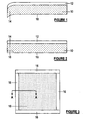
Figure 1 is a cross-section through part of a prior art sintered laminated structure showing curling at one edge portion; -
Figure 2 is the same cross-section asFigure 1 , but with the laminated structure modified in accordance with the invention to alleviate curling along the at least one edge; and -
Figure 3 is a plan view from below of the laminated structure ofFigure 2 prior to sintering - the cross-section A-A ofFigure 2 is shown inFigure 3 . - Referring to
Figure 1 , there is shown part of a sub-structure of a solid oxide fuel cell comprising ananode layer 10 and anelectrolyte layer 12, including oneedge portion 14 of the sub-structure. The overall sub-structure has a rectangular configuration with dimensions of about 110 x 90mm, and theanode layer 10 has a thickness in the range of about 0.5 to 1.0mm, for example 0.9mm, while the solidoxide electrolyte layer 12 has a thickness in the range of 10 to 50 microns, for example about 20 microns. These dimensions are given by way of illustration only, and other arrangements are possible. For example, as described theanode layer 10 will be the support structure in the fuel cell, but in other embodiments a thicker electrolyte layer may be used as the support layer for a thinner anode layer. - The solid
oxide electrolyte layer 12 comprises Y2O3-doped ZrO2 (YSZ) which has been sintered into a dense layer to provide a barrier to fuel gas on the side of theanode layer 10 and oxygen-containing gas on the other side. Theanode layer 10 comprises a porous Ni-YSZ cermet which in use permits the fuel gas to pass therethrough and react at the anode/electrolyte interface. The complete fuel cell will include a sintered porous cathode layer on the other side of theelectrolyte layer 12. - The sub-structure partly illustrated in
Figure 1 is formed by tape casting a green anode material, optionally in plural layers (not illustrated) with varying levels of binder content. The green material has a particle size in the range of about 0.5 to about 10 microns and the particulate material is held together by a binder such as acrylic binder at a binder content of about 23 wt% of the green anode material to provide a porous structure. - The green solid oxide electrolyte material is tape cast and roll laminated onto the green anode material and has a particle size in the range of about 0.5 to about 5 microns with the particulate material being held together by a binder such as polyvinyl butyral at a binder content also of about 23 wt% of the green electrolyte material. This preferred relatively high binder content in the green electrolyte material was adopted in an attempt to match the shrinkage rate of the porous anode material, but this is not possible given the different densities of the materials and on sintering the sub-structure at a temperature in the range of about 900 to about 1400°C the edges of the sub-structure curl away from the denser electrolyte layer as the more porous anode layer tries to shrink more, as shown at the one
edge portion 14 inFigure 1 . - The curling of the edges of the sub-structure is not desirable in a fuel cell and must be ground off the anode layer, or the curled edges may be trimmed off. Alternatively, the anode layer may be fired first, before the green electrolyte material is disposed on it and then fired, but this is equally inconvenient. Eventually, a thin cathode layer of, for example, strontium-doped lanthanum manganite having a thickness in the range of about 50 to 100 microns is screen printed onto the side of the
electrolyte layer 12 remote from theanode layer 10. - In accordance with the invention, it has now been found that the curling of the edges of the sub-structure described with reference to
Figure 1 may be alleviated by providing anedge strip 16 of denser green material than the green anode material on theface 18 of the green anode material remote from the electrolyte material along saidedge portion 14. - As illustrated, the
strip 16 has a width of about 7mm and a thickness in the range of about 20 to 50 microns, for example about 30 to 40 microns, preferably about 35 microns. The green material of theedge strip 16 is substantially identical to that of theelectrolyte layer 12, that is YSZ having a similar density with a binder content in the range of 17 to 25 wt% of the overall strip green material. The preferred binder content of the green strip material may be determined by trial and error at a level which alleviates the curling of theedge portion 14, and in one embodiment it has been found that a binder content of about 20 wt% is satisfactory compared to a binder content of about 23 wt% for the green material of the electrolyte layer. - The green material of the edge strip may be tape cast at the desired width or may be cut from a wider tape. Prior to application of the green strip material to the
face 18 of the green anode material, a light coating of solvent/plasticiser mix is applied, for example by brushing, to theedge portion 14 of theface 18 to which the strip of green material is to be applied. The solvent may be ethanol and the plasticiser benzyl butyl phthalate mixed in a weight ratio of about 2.5 to 5:1, preferably about 3.5:1. The green strip material is then applied to theedge portion 14 and air bubbles are rolled out. - This procedure is repeated along all of the edges of the
face 18 of the green anode material and, as illustrated, the green strips are then pressed into the green anode material. The overall sub-structure is then fired at the usual temperature of about 1400°C to produce, after firing, a sub-structure in which the edges are at least substantially flat. In the example described, the edge curl was less than 0.2mm in a batch of the sintered laminated structures, with many showing edge curl of less than 0.1 mm, compared to edge curl of at least 2mm, and as great 5mm, in the aforementioned comparative example without the edge strips. - Those skilled in the art will appreciate that the invention described herein is susceptible to variations and modifications other than those specifically described. It is to be understood that the invention includes all such variations and modifications which fall within the scope of the claims.
- Throughout this specification and the claims which follow, unless the context requires otherwise, the word "comprise", and variations such as "comprises" and "comprising", will be understood to imply the inclusion of a stated integer or step or group of integers or steps but not the exclusion of any other integer or step or group of integers or steps.
- The reference to any prior art in this specification is not, and should not be taken as, an acknowledgment or any form of suggestion that that prior art forms part of the common general knowledge.
Claims (45)
- A method of forming a sintered laminated structure in which first and second layers of green sinterable material are laminated so that the second layer is on one face of the first layer and extends to at least one edge of the first layer and fired, the material of the second layer having a shrinkage rate during firing which is less than that of the material of the first layer, characterised in that an edge strip of green sinterable material is applied to an opposite face of the first layer along said at least one edge prior to firing the first and second layers to form with the first and second layers a green laminated structure, the material of said strip having a shrinkage rate during firing which is less than that of the material of the first layer and the width of the edge strip along said one edge being no more than about 20% of the parallel dimension of the first layer, and in that the green laminated structure is fired to form the sintered laminated structure.
- A method according to claim 1 in which the width of the edge strip along said one edge is in the range of about 5 to 10% of the parallel dimension of the first layer.
- A method according to claim 1 or 2 in which the second layer extends to all edges of the first layer on said one face and the edge strip extends to all of said edges.
- A method according to any one of claims 1 to 3 in which the edge strip is formed in plural parts.
- A method according to any one of the preceding claims in which the shrinkage rate of the edge strip differs by no more than 25% from the shrinkage rate of the second layer.
- A method according to claim 5 which the shrinkage rate of the edge strip differs by no more than 10% from the shrinkage rate of the second layer.
- A method according to any one of the preceding claims in which the width of the edge strip is no greater than about the width of the edge portion of the laminated structure which would curl but for the presence of the edge strip.
- A method according to any one of the preceding claims in which the thickness of the edge strip is within about 25% of that of the second layer.
- A method according to any one of the preceding claims in which the edge strip has a density up to 10% greater than that of the second layer.
- A method according to any one of the preceding claims in which the sinterable material of the edge strip and the sinterable material of the second layer are closely similar.
- A method according to claim 10 in which the sinterable material of the second layer is Y2O3-doped ZrO2 and the sinterable material of the edge strip is ZrO2, optionally doped with Y2O3.
- A method according to claim 10 or claim 11 in which the sinterable material of each of the edge strip and second layer are held together with a respective binder, and wherein the percentage binder content of the edge strip is up to about 20% less than that of the second layer.
- A method according to claim 12 in which the percentage binder contact of the edge strip is about 15% less than that of the second layer.
- A method according to any one of the preceding claims in which the second layer has a binder content in the range of about 20 to 25 wt% of the sinterable material.
- A method according to any one of the preceding claims in which the edge strip is bonded to the opposed face of the first layer.
- A method according to claim 15 in which plasticiser and/or solvent material is applied to the opposed face of the first layer along said at least one edge prior to application of the edge strip thereto.
- A method according to any one of the preceding claims in which the edge strip is at least partly embedded in the first layer.
- A method according to any one of the preceding claims in which the edge strip is tape cast on to the first layer.
- A method according to any one of claims 1 to 17 in which the edge strip is screen printed on to the first layer.
- A method according to any one of the preceding claims in which one or both of the first layer and second layer is formed of plural layers of green sinterable material laminated together.
- A method according to any one of the preceding claims in which the first layer is an anode layer of a solid oxide fuel cell and the second layer is an electrolyte layer of the solid oxide fuel cell, and wherein the method includes the step of applying a cathode layer of green sinterable material on a face of the second layer remote from the first layer and firing the green sinterable material of the cathode layer.
- A method according to claim 21 in which the cathode layer is applied and fired after the first layer, second layer and edge strip have been sintered together.
- A method according to claim 21 or claim 22 in which the cathode layer does not extend to the edges of the second layer.
- A method according to any one of the preceding claims in which after the firing step the edge strip is removed from the sintered laminated structure.
- A green laminated structure comprising a first layer of green sinterable material having a first shrinkage rate during firing and a second layer of green sinterable material on one face of the first layer extending to at least one edge of the first layer, the material of the second layer having a second shrinkage rate during firing which is less than the first shrinkage rate, characterised in that the laminated structure has an edge strip of green sinterable material disposed on an opposite face of the first layer along said at least one edge, the material of said strip having a shrinkage rate during firing which is less than said first shrinkage rate and the width of the edge strip along said one edge being no more than about 20% of the parallel dimension of the first layer.
- A green laminated structure according to claim 25 in which the width of the edge strip along said one edge is in the range of about 5 to 10% of the parallel dimension of the first layer.
- A green laminated structure according to claim 25 or 26 in which the second layer extends to all edges of the first layer on said one face and the edge strip extends to all of said edges.
- A green laminated structure according to any one of claims 25 to 27 in which the edge strip is in plural parts.
- A green laminated structure according to any one of claims 25 to 28 in which the shrinkage rate of the edge strip differs by no more than 25% from the shrinkage rate of the second layer.
- A green laminated structure according to claim 29 in which the shrinkage rate of the edge strip differs by no more than 10% from the shrinkage rate of the second layer.
- A green laminated structure according to any one of claims 25 to 30 in which the width of the edge strip is no greater than about the width of the edge portion of the laminated structure which would curl but for the presence of the edge strip.
- A green laminated structure according to any one of claims 25 to 31 in which the thickness of the edge strip is within about 25% of that of the second layer.
- A green laminated structure according to any one of claims 25 to 32 in which the edge strip has a density up to 10% greater than that of the second layer.
- A green laminated structure according to any one of claims 25 to 33 in which the sinterable material of the edge strip and the sinterable material of the second layer are closely similar.
- A green laminated structure according to claim 34 in which the sinterable material of the second layer is Y2O3-doped ZrO2 and the sinterable material of the edge strip is ZrO2, optionally doped with Y2O3.
- A green laminated structure according to claim 34 or claim 35 in which the sinterable material of each of the edge strip and second layer are held together with a respective binder, and wherein the percentage binder contact of the edge strip is up to about 20% less than that of the second layer.
- A green laminated structure according to claim 36 in which the percentage binder contact of the edge strip is about 15% less than that of the second layer.
- A green laminated structure according to any one of claims 25 to 37 in which the second layer has a binder content in the range of about 20 to 25 wt% of the sinterable material.
- A green laminated structure according to any one of claims 25 to 38 in which the edge strip is bonded to the opposed face of the first layer.
- A green laminated structure according to claim 39 in which plasticiser and/or solvent material is applied to the opposed face of the first layer along said at least one edge prior to application of the edge strip thereto.
- A green laminated structure according to any one of claims 25 to 40 in which the edge strip is at least partly embedded in the first layer.
- A green laminated structure according to any one of claims 25 to 41 in which the edge strip is tape cast on to the first layer.
- A green laminated structure according to any one of claims 25 to 41 in which the edge strip is screen printed on to the first layer.
- A green laminated structure according to any one of claims 25 to 43 in which one or both of the first layer and second layer is formed of plural layers of green sinterable material laminated together.
- A green laminated structure according to any one of claims 25 to 44 in which the first layer is an anode layer of a solid oxide fuel cell and the second layer is an electrolyte layer of the solid oxide fuel cell.
Applications Claiming Priority (3)
| Application Number | Priority Date | Filing Date | Title |
|---|---|---|---|
| AUPQ4921A AUPQ492199A0 (en) | 1999-12-30 | 1999-12-30 | Laminated structure and method of forming same |
| AUPQ492199 | 1999-12-30 | ||
| PCT/AU2000/001560 WO2001049485A1 (en) | 1999-12-30 | 2000-12-19 | Laminated structure and method of forming same |
Publications (3)
| Publication Number | Publication Date |
|---|---|
| EP1255641A1 EP1255641A1 (en) | 2002-11-13 |
| EP1255641A4 EP1255641A4 (en) | 2005-01-12 |
| EP1255641B1 true EP1255641B1 (en) | 2010-04-28 |
Family
ID=3819057
Family Applications (1)
| Application Number | Title | Priority Date | Filing Date |
|---|---|---|---|
| EP00986863A Expired - Lifetime EP1255641B1 (en) | 1999-12-30 | 2000-12-19 | Laminated structure and method of forming same |
Country Status (9)
| Country | Link |
|---|---|
| US (1) | US7045239B2 (en) |
| EP (1) | EP1255641B1 (en) |
| JP (1) | JP4845315B2 (en) |
| AT (1) | ATE465868T1 (en) |
| AU (1) | AUPQ492199A0 (en) |
| CA (1) | CA2395060C (en) |
| DE (1) | DE60044304D1 (en) |
| WO (1) | WO2001049485A1 (en) |
| ZA (1) | ZA200205067B (en) |
Families Citing this family (19)
| Publication number | Priority date | Publication date | Assignee | Title |
|---|---|---|---|---|
| JP4252453B2 (en) * | 2001-09-26 | 2009-04-08 | 日本碍子株式会社 | Electrochemical cell and method for producing the same |
| JP4923407B2 (en) * | 2004-01-16 | 2012-04-25 | 三菱マテリアル株式会社 | Method for producing solid oxide fuel cell |
| US9246184B1 (en) | 2007-11-13 | 2016-01-26 | Bloom Energy Corporation | Electrolyte supported cell designed for longer life and higher power |
| US8067129B2 (en) | 2007-11-13 | 2011-11-29 | Bloom Energy Corporation | Electrolyte supported cell designed for longer life and higher power |
| EP2083465B1 (en) * | 2008-01-23 | 2012-08-01 | Institute of Nuclear Energy Research | A Process for Fabrication of a Fully Dense Electrolyte layer embedded in membrane electrolyte assembly of solid oxide fuel cell |
| JP4960903B2 (en) * | 2008-02-27 | 2012-06-27 | 本田技研工業株式会社 | Laminate inspection method, inspection apparatus, and inspection program |
| JP5428178B2 (en) * | 2008-03-28 | 2014-02-26 | 大日本印刷株式会社 | Method for producing solid oxide fuel cell and laminate |
| JP2009245717A (en) * | 2008-03-31 | 2009-10-22 | Dainippon Printing Co Ltd | Method of manufacturing solid oxide fuel cell, solid oxide fuel cell manufactured by this method, and electrolyte-electrode stack for solid oxide fuel cell |
| JP5932232B2 (en) * | 2011-03-25 | 2016-06-08 | 株式会社日本触媒 | Anode-supported half cell, anode-supported cell using the same, and method for producing anode-supported half-cell |
| KR101351221B1 (en) * | 2011-09-21 | 2014-01-14 | 한국전력공사 | Fabrication Method of Substrate-Supported Coating Layers by Using Tape Casting Film Sheet |
| TW201345869A (en) | 2012-04-18 | 2013-11-16 | Nitto Denko Corp | Method and apparatus for sintering flat ceramics |
| US9205571B2 (en) | 2012-04-18 | 2015-12-08 | Nitto Denko Corporation | Method and apparatus for sintering flat ceramics |
| JP5973377B2 (en) * | 2013-04-24 | 2016-08-23 | 株式会社ノリタケカンパニーリミテド | Green sheet for solid oxide fuel cell and method for producing the same |
| JP5699347B2 (en) * | 2013-09-12 | 2015-04-08 | 大日本印刷株式会社 | Solid oxide fuel cell and method for producing solid oxide fuel cell |
| JP6162572B2 (en) * | 2013-10-25 | 2017-07-12 | 日本特殊陶業株式会社 | Method for producing solid oxide fuel cell single cell and method for producing solid oxide fuel cell stack |
| US9673470B2 (en) * | 2014-01-22 | 2017-06-06 | King Fahd University Of Petroleum And Minerals | Electrolyte layer having a patchwork-type nanoporous grain boundary and a method of preparation thereof |
| JP6443662B2 (en) * | 2014-10-21 | 2018-12-26 | 日産自動車株式会社 | Manufacturing method of fuel cell |
| US10347930B2 (en) | 2015-03-24 | 2019-07-09 | Bloom Energy Corporation | Perimeter electrolyte reinforcement layer composition for solid oxide fuel cell electrolytes |
| JP6060297B2 (en) * | 2016-04-28 | 2017-01-11 | 株式会社日本触媒 | Anode-supported half cell and anode-supported cell using the same |
Family Cites Families (25)
| Publication number | Priority date | Publication date | Assignee | Title |
|---|---|---|---|---|
| US3879509A (en) * | 1971-09-07 | 1975-04-22 | Gilbert James Elderbaum | Method of producing thin ceramic sheets with minimal distortion |
| NL7310168A (en) * | 1973-07-20 | 1975-01-22 | Hitachi Ltd | Sintered laminated integrated circuit unit - mfd. from ceramic, and printed conducting assemblies on a ceramic substrate |
| CH626314A5 (en) * | 1976-09-02 | 1981-11-13 | Gail Tonwerke Wilhelm | Ceramic veneer |
| JPH037086Y2 (en) * | 1986-01-29 | 1991-02-21 | ||
| US5130067A (en) | 1986-05-02 | 1992-07-14 | International Business Machines Corporation | Method and means for co-sintering ceramic/metal mlc substrates |
| JPS63112473A (en) * | 1986-10-28 | 1988-05-17 | 太陽誘電株式会社 | Manufacture of ceramic substrate |
| US4883497A (en) | 1988-03-28 | 1989-11-28 | Arch Development Corporation | Formation of thin walled ceramic solid oxide fuel cells |
| JPH037086A (en) * | 1989-05-31 | 1991-01-14 | Sanken Electric Co Ltd | Motor controlling method |
| JPH03271165A (en) * | 1990-03-20 | 1991-12-03 | Fujitsu General Ltd | Burning of sheet laminated material |
| JPH04298963A (en) * | 1991-03-27 | 1992-10-22 | Ngk Insulators Ltd | Solid electrolyte type fuel cell and manufacture thereof |
| JP2945157B2 (en) | 1991-03-27 | 1999-09-06 | 日本碍子株式会社 | Solid oxide fuel cell and method of manufacturing the same |
| JPH04298964A (en) | 1991-03-27 | 1992-10-22 | Ngk Insulators Ltd | Solid electrolyte type fuel cell and manufacture thereof |
| JP3413880B2 (en) * | 1993-07-16 | 2003-06-09 | 松下電器産業株式会社 | Method for producing multilayer ceramic sintered body |
| JPH07335239A (en) * | 1994-06-08 | 1995-12-22 | Ngk Insulators Ltd | Manufacture of junction body |
| DE19512146A1 (en) * | 1995-03-31 | 1996-10-02 | Inst Neue Mat Gemein Gmbh | Process for the production of shrink-adapted ceramic composites |
| JP3230423B2 (en) * | 1995-09-12 | 2001-11-19 | 日本電信電話株式会社 | Hollow flat electrode substrate and method of manufacturing the same |
| US5670270A (en) * | 1995-11-16 | 1997-09-23 | The Dow Chemical Company | Electrode structure for solid state electrochemical devices |
| JPH09143512A (en) * | 1995-11-29 | 1997-06-03 | Chichibu Onoda Cement Corp | Production of multilayer sintered compact |
| EP0813254B1 (en) * | 1996-06-14 | 2001-10-17 | Ngk Insulators, Ltd. | Method for producing ceramic diaphragm structure |
| JP3492492B2 (en) * | 1996-06-14 | 2004-02-03 | 日本碍子株式会社 | Manufacturing method of ceramic diaphragm structure |
| JPH10167842A (en) * | 1996-12-16 | 1998-06-23 | Sumitomo Kinzoku Erekutorodebaisu:Kk | Ceramic green sheet for restricting layer and production of ceramic substrate using that |
| US5935727A (en) | 1997-04-10 | 1999-08-10 | The Dow Chemical Company | Solid oxide fuel cells |
| AUPO724997A0 (en) * | 1997-06-10 | 1997-07-03 | Ceramic Fuel Cells Limited | A fuel cell assembly |
| JP4300493B2 (en) * | 1998-06-05 | 2009-07-22 | 日立金属株式会社 | Ceramic laminate and manufacturing method thereof |
| US6458170B1 (en) * | 1998-12-03 | 2002-10-01 | The Regents Of The University Of California | Method for making thin, flat, dense membranes on porous substrates |
-
1999
- 1999-12-30 AU AUPQ4921A patent/AUPQ492199A0/en not_active Abandoned
-
2000
- 2000-12-19 CA CA002395060A patent/CA2395060C/en not_active Expired - Fee Related
- 2000-12-19 WO PCT/AU2000/001560 patent/WO2001049485A1/en active IP Right Grant
- 2000-12-19 JP JP2001549832A patent/JP4845315B2/en not_active Expired - Fee Related
- 2000-12-19 DE DE60044304T patent/DE60044304D1/en not_active Expired - Lifetime
- 2000-12-19 AT AT00986863T patent/ATE465868T1/en not_active IP Right Cessation
- 2000-12-19 EP EP00986863A patent/EP1255641B1/en not_active Expired - Lifetime
- 2000-12-19 US US10/169,386 patent/US7045239B2/en not_active Expired - Fee Related
-
2002
- 2002-06-24 ZA ZA200205067A patent/ZA200205067B/en unknown
Also Published As
| Publication number | Publication date |
|---|---|
| US7045239B2 (en) | 2006-05-16 |
| ZA200205067B (en) | 2003-10-07 |
| EP1255641A4 (en) | 2005-01-12 |
| US20030129460A1 (en) | 2003-07-10 |
| CA2395060C (en) | 2008-07-08 |
| CA2395060A1 (en) | 2001-07-12 |
| JP4845315B2 (en) | 2011-12-28 |
| WO2001049485A1 (en) | 2001-07-12 |
| DE60044304D1 (en) | 2010-06-10 |
| EP1255641A1 (en) | 2002-11-13 |
| AUPQ492199A0 (en) | 2000-02-03 |
| ATE465868T1 (en) | 2010-05-15 |
| JP2003519023A (en) | 2003-06-17 |
Similar Documents
| Publication | Publication Date | Title |
|---|---|---|
| EP1255641B1 (en) | Laminated structure and method of forming same | |
| CA2597997C (en) | Fuel cell cathodes | |
| EP0815608B1 (en) | Solid oxide fuel cells with specific electrode layers | |
| US5342705A (en) | Monolithic fuel cell having a multilayer interconnect | |
| US20060024547A1 (en) | Anode supported sofc with an electrode multifunctional layer | |
| EP2347463B1 (en) | A solid oxide fuel cell or solid oxide fuel cell sub-component and methods of preparing same | |
| US9070946B2 (en) | Electrolyte-electrode joined assembly and method for producing the same | |
| JP2009507356A (en) | Ceramic membrane with integral seal and support, and electrochemical cell and electrochemical cell stack structure including the same | |
| WO2006050071A2 (en) | Ceramic laminate structures | |
| KR100849994B1 (en) | Pressure Device for manufacturing Solid Oxide Fuel Cell and Manufacturing Method Using the Same | |
| US20080299434A1 (en) | Solid oxide type fuel cell and manufacturing method thereof | |
| EP1096588A2 (en) | Solid oxide fuel cell with sintered air electrode | |
| KR101685386B1 (en) | Anode Supported Solid Oxide Fuel Cell by using low temperature co-firing and manufacturing method thereof | |
| EP3051617A1 (en) | Solid oxide fuel cell stack and method for manufacturing same | |
| AU782584B2 (en) | Laminated structure and method of forming same | |
| CA2735868A1 (en) | Optimized cell configurations for stable lscf-based solid oxide fuel cells | |
| JP2009009738A (en) | Solid electrolyte fuel cell and its manufacturing method | |
| JP7330689B2 (en) | Fuel cells and fuel cell stacks | |
| JP6965041B2 (en) | Electrochemical reaction single cell and electrochemical reaction cell stack | |
| WO2010095728A1 (en) | Electrolyte electrode assembly and method for producing the same | |
| CN113394434A (en) | Solid oxide fuel cell and method for manufacturing same | |
| KR102100257B1 (en) | Plate-type unit cell for solid oxide fuel cell with high strength | |
| JPH09190824A (en) | Fuel electrode structure of fuel cell of solid electrolyte type and manufacture thereof | |
| JPH08180886A (en) | Method for reducing contact resistance of air electrode of solid electrolytic fuel cell |
Legal Events
| Date | Code | Title | Description |
|---|---|---|---|
| PUAI | Public reference made under article 153(3) epc to a published international application that has entered the european phase |
Free format text: ORIGINAL CODE: 0009012 |
|
| 17P | Request for examination filed |
Effective date: 20020704 |
|
| AK | Designated contracting states |
Kind code of ref document: A1 Designated state(s): AT BE CH CY DE DK ES FI FR GB GR IE IT LI LU MC NL PT SE TR |
|
| AX | Request for extension of the european patent |
Free format text: AL;LT;LV;MK;RO;SI |
|
| A4 | Supplementary search report drawn up and despatched |
Effective date: 20041126 |
|
| RIC1 | Information provided on ipc code assigned before grant |
Ipc: 7H 01M 8/12 B Ipc: 7B 32B 18/00 A Ipc: 7C 04B 35/486 B Ipc: 7C 04B 35/01 B Ipc: 7B 32B 31/00 B |
|
| 17Q | First examination report despatched |
Effective date: 20050222 |
|
| GRAP | Despatch of communication of intention to grant a patent |
Free format text: ORIGINAL CODE: EPIDOSNIGR1 |
|
| RIC1 | Information provided on ipc code assigned before grant |
Ipc: B32B 37/00 20060101ALI20091103BHEP Ipc: C04B 35/01 20060101ALI20091103BHEP Ipc: C04B 35/486 20060101ALI20091103BHEP Ipc: B32B 18/00 20060101AFI20091103BHEP Ipc: H01M 8/12 20060101ALI20091103BHEP |
|
| GRAS | Grant fee paid |
Free format text: ORIGINAL CODE: EPIDOSNIGR3 |
|
| GRAA | (expected) grant |
Free format text: ORIGINAL CODE: 0009210 |
|
| AK | Designated contracting states |
Kind code of ref document: B1 Designated state(s): AT BE CH CY DE DK ES FI FR GB GR IE IT LI LU MC NL PT SE TR |
|
| REG | Reference to a national code |
Ref country code: GB Ref legal event code: FG4D |
|
| REG | Reference to a national code |
Ref country code: CH Ref legal event code: EP |
|
| REG | Reference to a national code |
Ref country code: IE Ref legal event code: FG4D |
|
| REF | Corresponds to: |
Ref document number: 60044304 Country of ref document: DE Date of ref document: 20100610 Kind code of ref document: P |
|
| REG | Reference to a national code |
Ref country code: NL Ref legal event code: VDEP Effective date: 20100428 |
|
| PG25 | Lapsed in a contracting state [announced via postgrant information from national office to epo] |
Ref country code: ES Free format text: LAPSE BECAUSE OF FAILURE TO SUBMIT A TRANSLATION OF THE DESCRIPTION OR TO PAY THE FEE WITHIN THE PRESCRIBED TIME-LIMIT Effective date: 20100808 Ref country code: SE Free format text: LAPSE BECAUSE OF FAILURE TO SUBMIT A TRANSLATION OF THE DESCRIPTION OR TO PAY THE FEE WITHIN THE PRESCRIBED TIME-LIMIT Effective date: 20100428 Ref country code: NL Free format text: LAPSE BECAUSE OF FAILURE TO SUBMIT A TRANSLATION OF THE DESCRIPTION OR TO PAY THE FEE WITHIN THE PRESCRIBED TIME-LIMIT Effective date: 20100428 |
|
| PG25 | Lapsed in a contracting state [announced via postgrant information from national office to epo] |
Ref country code: AT Free format text: LAPSE BECAUSE OF FAILURE TO SUBMIT A TRANSLATION OF THE DESCRIPTION OR TO PAY THE FEE WITHIN THE PRESCRIBED TIME-LIMIT Effective date: 20100428 Ref country code: FI Free format text: LAPSE BECAUSE OF FAILURE TO SUBMIT A TRANSLATION OF THE DESCRIPTION OR TO PAY THE FEE WITHIN THE PRESCRIBED TIME-LIMIT Effective date: 20100428 |
|
| PG25 | Lapsed in a contracting state [announced via postgrant information from national office to epo] |
Ref country code: CY Free format text: LAPSE BECAUSE OF FAILURE TO SUBMIT A TRANSLATION OF THE DESCRIPTION OR TO PAY THE FEE WITHIN THE PRESCRIBED TIME-LIMIT Effective date: 20100428 Ref country code: GR Free format text: LAPSE BECAUSE OF FAILURE TO SUBMIT A TRANSLATION OF THE DESCRIPTION OR TO PAY THE FEE WITHIN THE PRESCRIBED TIME-LIMIT Effective date: 20100729 |
|
| PG25 | Lapsed in a contracting state [announced via postgrant information from national office to epo] |
Ref country code: PT Free format text: LAPSE BECAUSE OF FAILURE TO SUBMIT A TRANSLATION OF THE DESCRIPTION OR TO PAY THE FEE WITHIN THE PRESCRIBED TIME-LIMIT Effective date: 20100830 Ref country code: DK Free format text: LAPSE BECAUSE OF FAILURE TO SUBMIT A TRANSLATION OF THE DESCRIPTION OR TO PAY THE FEE WITHIN THE PRESCRIBED TIME-LIMIT Effective date: 20100428 |
|
| PG25 | Lapsed in a contracting state [announced via postgrant information from national office to epo] |
Ref country code: BE Free format text: LAPSE BECAUSE OF FAILURE TO SUBMIT A TRANSLATION OF THE DESCRIPTION OR TO PAY THE FEE WITHIN THE PRESCRIBED TIME-LIMIT Effective date: 20100428 |
|
| PLBE | No opposition filed within time limit |
Free format text: ORIGINAL CODE: 0009261 |
|
| STAA | Information on the status of an ep patent application or granted ep patent |
Free format text: STATUS: NO OPPOSITION FILED WITHIN TIME LIMIT |
|
| 26N | No opposition filed |
Effective date: 20110131 |
|
| PG25 | Lapsed in a contracting state [announced via postgrant information from national office to epo] |
Ref country code: MC Free format text: LAPSE BECAUSE OF NON-PAYMENT OF DUE FEES Effective date: 20101231 |
|
| REG | Reference to a national code |
Ref country code: CH Ref legal event code: PL |
|
| PG25 | Lapsed in a contracting state [announced via postgrant information from national office to epo] |
Ref country code: LI Free format text: LAPSE BECAUSE OF NON-PAYMENT OF DUE FEES Effective date: 20101231 Ref country code: IE Free format text: LAPSE BECAUSE OF NON-PAYMENT OF DUE FEES Effective date: 20101219 Ref country code: CH Free format text: LAPSE BECAUSE OF NON-PAYMENT OF DUE FEES Effective date: 20101231 |
|
| PG25 | Lapsed in a contracting state [announced via postgrant information from national office to epo] |
Ref country code: LU Free format text: LAPSE BECAUSE OF NON-PAYMENT OF DUE FEES Effective date: 20101219 |
|
| PG25 | Lapsed in a contracting state [announced via postgrant information from national office to epo] |
Ref country code: TR Free format text: LAPSE BECAUSE OF FAILURE TO SUBMIT A TRANSLATION OF THE DESCRIPTION OR TO PAY THE FEE WITHIN THE PRESCRIBED TIME-LIMIT Effective date: 20100428 |
|
| PGFP | Annual fee paid to national office [announced via postgrant information from national office to epo] |
Ref country code: GB Payment date: 20131219 Year of fee payment: 14 Ref country code: DE Payment date: 20131220 Year of fee payment: 14 |
|
| PGFP | Annual fee paid to national office [announced via postgrant information from national office to epo] |
Ref country code: IT Payment date: 20131218 Year of fee payment: 14 |
|
| PGFP | Annual fee paid to national office [announced via postgrant information from national office to epo] |
Ref country code: FR Payment date: 20131220 Year of fee payment: 14 |
|
| REG | Reference to a national code |
Ref country code: DE Ref legal event code: R119 Ref document number: 60044304 Country of ref document: DE |
|
| GBPC | Gb: european patent ceased through non-payment of renewal fee |
Effective date: 20141219 |
|
| REG | Reference to a national code |
Ref country code: FR Ref legal event code: ST Effective date: 20150831 |
|
| PG25 | Lapsed in a contracting state [announced via postgrant information from national office to epo] |
Ref country code: GB Free format text: LAPSE BECAUSE OF NON-PAYMENT OF DUE FEES Effective date: 20141219 Ref country code: DE Free format text: LAPSE BECAUSE OF NON-PAYMENT OF DUE FEES Effective date: 20150701 |
|
| PG25 | Lapsed in a contracting state [announced via postgrant information from national office to epo] |
Ref country code: FR Free format text: LAPSE BECAUSE OF NON-PAYMENT OF DUE FEES Effective date: 20141231 |
|
| PG25 | Lapsed in a contracting state [announced via postgrant information from national office to epo] |
Ref country code: IT Free format text: LAPSE BECAUSE OF NON-PAYMENT OF DUE FEES Effective date: 20141219 |