EP1255050B1 - Beschlag - Google Patents
Beschlag Download PDFInfo
- Publication number
- EP1255050B1 EP1255050B1 EP02009698A EP02009698A EP1255050B1 EP 1255050 B1 EP1255050 B1 EP 1255050B1 EP 02009698 A EP02009698 A EP 02009698A EP 02009698 A EP02009698 A EP 02009698A EP 1255050 B1 EP1255050 B1 EP 1255050B1
- Authority
- EP
- European Patent Office
- Prior art keywords
- bolt
- longitudinal axis
- fitting according
- conical extension
- conical
- Prior art date
- Legal status (The legal status is an assumption and is not a legal conclusion. Google has not performed a legal analysis and makes no representation as to the accuracy of the status listed.)
- Expired - Lifetime
Links
Images




Classifications
-
- F—MECHANICAL ENGINEERING; LIGHTING; HEATING; WEAPONS; BLASTING
- F16—ENGINEERING ELEMENTS AND UNITS; GENERAL MEASURES FOR PRODUCING AND MAINTAINING EFFECTIVE FUNCTIONING OF MACHINES OR INSTALLATIONS; THERMAL INSULATION IN GENERAL
- F16B—DEVICES FOR FASTENING OR SECURING CONSTRUCTIONAL ELEMENTS OR MACHINE PARTS TOGETHER, e.g. NAILS, BOLTS, CIRCLIPS, CLAMPS, CLIPS OR WEDGES; JOINTS OR JOINTING
- F16B21/00—Means for preventing relative axial movement of a pin, spigot, shaft or the like and a member surrounding it; Stud-and-socket releasable fastenings
- F16B21/02—Releasable fastening devices locking by rotation
-
- E—FIXED CONSTRUCTIONS
- E04—BUILDING
- E04C—STRUCTURAL ELEMENTS; BUILDING MATERIALS
- E04C5/00—Reinforcing elements, e.g. for concrete; Auxiliary elements therefor
- E04C5/01—Reinforcing elements of metal, e.g. with non-structural coatings
- E04C5/06—Reinforcing elements of metal, e.g. with non-structural coatings of high bending resistance, i.e. of essentially three-dimensional [3D] extent, e.g. lattice girders
- E04C5/0645—Shear reinforcements, e.g. shearheads for floor slabs
-
- F—MECHANICAL ENGINEERING; LIGHTING; HEATING; WEAPONS; BLASTING
- F16—ENGINEERING ELEMENTS AND UNITS; GENERAL MEASURES FOR PRODUCING AND MAINTAINING EFFECTIVE FUNCTIONING OF MACHINES OR INSTALLATIONS; THERMAL INSULATION IN GENERAL
- F16B—DEVICES FOR FASTENING OR SECURING CONSTRUCTIONAL ELEMENTS OR MACHINE PARTS TOGETHER, e.g. NAILS, BOLTS, CIRCLIPS, CLAMPS, CLIPS OR WEDGES; JOINTS OR JOINTING
- F16B12/00—Jointing of furniture or the like, e.g. hidden from exterior
- F16B12/10—Jointing of furniture or the like, e.g. hidden from exterior using pegs, bolts, tenons, clamps, clips, or the like
- F16B2012/106—Connection bolts for connection fittings
-
- Y—GENERAL TAGGING OF NEW TECHNOLOGICAL DEVELOPMENTS; GENERAL TAGGING OF CROSS-SECTIONAL TECHNOLOGIES SPANNING OVER SEVERAL SECTIONS OF THE IPC; TECHNICAL SUBJECTS COVERED BY FORMER USPC CROSS-REFERENCE ART COLLECTIONS [XRACs] AND DIGESTS
- Y10—TECHNICAL SUBJECTS COVERED BY FORMER USPC
- Y10T—TECHNICAL SUBJECTS COVERED BY FORMER US CLASSIFICATION
- Y10T403/00—Joints and connections
- Y10T403/70—Interfitted members
Definitions
- the invention relates to a fitting for connecting two components, in particular plates, with one in the first component mounted clamping device and one in the second component fixable expansion sleeve with inserted by means of the clamping device opposite this longitudinally displaceable, the expansion sleeve by a cone expanding bolt.
- a fitting for connecting two components, in particular plates, with one in the first component mounted clamping device and one in the second component fixable expansion sleeve with inserted by means of the clamping device opposite this longitudinally displaceable, the expansion sleeve by a cone expanding bolt.
- the object of the present invention is therefore to provide a bolt to provide, wherein the expansion sleeve in the longitudinal direction seen as evenly as possible over a longer range is spread.
- the cone has an approximately conical projection on the bolt, whose longitudinal axis laterally offset to the bolt longitudinal axis is arranged. This ensures that when moving the bolt, the expansion sleeve spread over a relatively large longitudinal area is largely uniform, so that a secure anchoring of the same results in the bore.
- the longitudinal axes of the bolt and the conical extend Approach parallel to each other. It has as most favorable solution a displacement of the longitudinal axis of the conical Heel in a corresponding to the radius of the bolt Distance from the pin longitudinal axis proved.
- the cone-shaped approach is partially cut off laterally, with the cut surfaces parallel to the bolt longitudinal axis.
- the cone-shaped approach can still one or more have laterally projecting paragraphs whose surfaces in Extension of the conical surface run.
- the bolt is encapsulated by the expansion sleeve.
- this spreads better is an open to the outside Slot provided. This is expediently by at least an over the outer circumference of the conical approach protruding rib, which projects into the slot, the Syringes kept open.
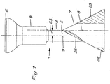
- FIG. 1 The apparent from Figure 1 bolt 1 is provided with a head 2, which for connecting two components, not shown with this in a likewise not shown clamping device intervenes.
- the head 2 is followed by a shaft 3, wherein the shaft part 5 in diameter over the short Shank part 4 is discontinued.
- Expansion sleeve 6 is as a cone in the embodiment according to Figure 1 at the end of the shaft part 5 arranged cone 7 provided.
- the longitudinal axis 8 of the cone 7 opposite the bolt longitudinal axis 9 laterally about the radius 23 of the shaft part 5 arranged offset and thus extends in extension the outer contour of the shaft part 5 parallel to Bolt longitudinal axis.
- the cone 11 is better for keeping it inside diameter to adapt the sleeve 6, laterally cut off, with the cut Surfaces 12 and 13 parallel to the bolt longitudinal axis. 9 run.
- the cone 11 at 14 to the diameter adapted to the shaft part 5.
- the bolt 15 is between the shank part 4 and the laterally cut cone 16 at his shank part 5 with parallel to the bolt longitudinal axis 9 extending Longitudinal ribs 17 provided for stabilization. It stands a rib 18 over the outer periphery of both the shank part. 5 as well as the shaft part 4 and protrudes into an outward open slot 19 of the sleeve 6 inside. This will achieve that the slot 19 during encapsulation of the bolt 1, 15 free remains and the sleeve 6 thereby spreads easier.
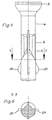
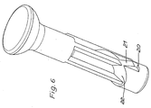
- the figures 4 to 6 show that the cone-shaped approach 16 still two laterally projecting paragraphs 20 connect, whose Surfaces 21 extend in extension of the conical surface 22. As FIG. 8 shows, in order to increase the spreading effect, they are on the circumference of the bolt 26 a plurality of conical projections 24 side by side intended.
Landscapes
- Engineering & Computer Science (AREA)
- Architecture (AREA)
- General Engineering & Computer Science (AREA)
- Mechanical Engineering (AREA)
- Civil Engineering (AREA)
- Structural Engineering (AREA)
- Dowels (AREA)
- Clamps And Clips (AREA)
- Connection Of Plates (AREA)
- Mechanical Coupling Of Light Guides (AREA)
- Mutual Connection Of Rods And Tubes (AREA)
- Insertion Pins And Rivets (AREA)
- Furniture Connections (AREA)
- Joining Of Building Structures In Genera (AREA)
- Massaging Devices (AREA)
- Infusion, Injection, And Reservoir Apparatuses (AREA)
Description
- Figur 1
- die Ansicht eines Bolzens mit einem Kegel als Konus,
- Figur 2
- eine Darstellung nach Figur 1 mit teilweise abgeschnittenem Kegel,
- Figur 3
- eine Darstellung nach Figur 2 einer anderen Ausführungsform,
- Figur 4
- eine um 90° gedrehte Darstellung nach Figur 3,
- Figur 5
- den Schnitt V-V nach Figur 4,
- Figur 6
- eine perspektivische Ansicht des Bolzens nach den Figuren 3 bis 5 und
- Figur 7
- die Ansicht eines Bolzens nach den Figuren 3 bis 6 mit umspritzter Spreizhülse,
- Figur 8
- eine Darstellung nach Figur 3 einer weiteren Ausführungsform.
Claims (9)
- Beschlag zum Verbinden von zwei Bauteilen, insbesondere Platten mit einer im ersten Bauteil gelagerten Spannvorrichtung und einer im zweiten Bauteil festlegbaren Spreizhülse (6) mit eingesetzten, mittels der Spannvorrichtung gegenüber dieser längsverschiebbaren, die Spreizhülse (6) durch einen Konus (7, 11, 16, 24) spreizenden Bolzen(1, 15, 26), dadurch gekennzeichnet, dass sich am Bolzen (1, 15, 26) als Konus ein etwa kegelförmiger Ansatz (7, 11, 16, 24) befindet, dessen Längsachse (8) seitlich versetzt zur Bolzenlängsachse (9) angeordnet ist.
- Beschlag nach Anspruch 1, dadurch gekennzeichnet, dass die Längsachsen (8, 9) des Bolzens und des kegelförmigen Ansatzes parallel verlaufen.
- Beschlag nach einem oder beiden der vorhergehenden Ansprüche, dadurch gekennzeichnet, dass die Längsachse (8) des kegelförmigen Ansatzes (7, 11, 16) in einem dem Radius (23) des Bolzens (1, 15) entsprechenden Abstand von der Bolzenlängsachse (9) verläuft.
- Beschlag nach einem oder mehreren der vorhergehenden Ansprüche, dadurch gekennzeichnet, dass der kegelförmige Ansatz (11, 16) zumindest teilweise seitlich abgeschnitten ist, wobei die abgeschnittenen Flächen (12, 13) parallel zur Bolzenlängsachse (9) verlaufen.
- Beschlag nach einem oder mehreren der vorhergehenden Ansprüche, dadurch gekennzeichnet, dass der kegelförmige Ansatz (16) ein oder mehrere seitlich abstehende Absätze (20) aufweist, deren Oberflächen (21) in Verlängerung der Kegelfläche (22) verlaufen.
- Beschlag, dessen Bolzen mit einem Kopf versehen ist, nach einem oder mehreren der vorhergehenden Ansprüche, dadurch gekennzeichnet, dass zwischen dem Bolzenkopf (2) und dem kegelförmigen Ansatz (16) ein oder mehrere parallel zur Bolzenlängsachse (9) verlaufende Längsrippen (17, 18) am Bolzenschaft (5) vorgesehen sind.
- Beschlag nach Anspruch 6, dadurch gekennzeichnet, dass mindestens eine Rippe (18) über den Außenumfang des kegelförmigen Ansatzes (16) hinaussteht und in einen nach aussen offenen Schlitz (19) der Spreizhülse (6) hineinragt.
- Beschlag nach einem oder mehreren der vorhergehenden Ansprüche, dadurch gekennzeichnet, dass der Bolzen (1) von der Spreizhülse (6) umspritzt ist.
- Beschlag nach einem oder mehreren der vorhergehenden Ansprüche, dadurch gekennzeichnet, dass am Umfang des Bolzens (26) mehrere kegelförmige Ansätze (24) nebeneinander vorgesehen sind.
Applications Claiming Priority (2)
| Application Number | Priority Date | Filing Date | Title |
|---|---|---|---|
| DE20107661U | 2001-05-05 | ||
| DE20107661U DE20107661U1 (de) | 2001-05-05 | 2001-05-05 | Beschlag |
Publications (3)
| Publication Number | Publication Date |
|---|---|
| EP1255050A2 EP1255050A2 (de) | 2002-11-06 |
| EP1255050A3 EP1255050A3 (de) | 2003-07-16 |
| EP1255050B1 true EP1255050B1 (de) | 2005-06-15 |
Family
ID=7956546
Family Applications (1)
| Application Number | Title | Priority Date | Filing Date |
|---|---|---|---|
| EP02009698A Expired - Lifetime EP1255050B1 (de) | 2001-05-05 | 2002-04-27 | Beschlag |
Country Status (11)
| Country | Link |
|---|---|
| US (1) | US6672810B2 (de) |
| EP (1) | EP1255050B1 (de) |
| CN (1) | CN1234974C (de) |
| AT (1) | ATE298047T1 (de) |
| CA (1) | CA2384720A1 (de) |
| DE (2) | DE20107661U1 (de) |
| ES (1) | ES2241922T3 (de) |
| PL (1) | PL353687A1 (de) |
| RU (1) | RU2229038C2 (de) |
| TR (1) | TR200201224A2 (de) |
| UA (1) | UA72006C2 (de) |
Families Citing this family (2)
| Publication number | Priority date | Publication date | Assignee | Title |
|---|---|---|---|---|
| DE502007002616D1 (de) * | 2007-04-21 | 2010-03-04 | Haefele Berlin Gmbh & Co Kg | Verfahren zur Herstellung einer Kunststoffmuffe |
| GB0819848D0 (en) * | 2008-10-29 | 2008-12-03 | Subsea Riser Products Ltd | Connector |
Family Cites Families (10)
| Publication number | Priority date | Publication date | Assignee | Title |
|---|---|---|---|---|
| US2903938A (en) * | 1956-01-18 | 1959-09-15 | Strand Sven Hugo | Anchor bolt having elastically connected wedge members |
| US4287807A (en) * | 1979-06-01 | 1981-09-08 | Usm Corporation | Pull-to-set anchoring device |
| DE3031048C2 (de) * | 1980-08-16 | 1985-02-28 | Upat Gmbh & Co, 7830 Emmendingen | Spreizanker |
| US4650385A (en) * | 1983-05-17 | 1987-03-17 | The United States Of America As Represented By The Administrator Of The National Aeronautics And Space Administration | Daze fasteners |
| DE3346537A1 (de) * | 1983-12-22 | 1985-07-11 | Hilti Ag, Schaan | Spreizanker |
| DE3507022A1 (de) * | 1985-02-28 | 1986-08-28 | Hilti Ag, Schaan | Spreizduebel mit setzanzeige |
| SU1449716A1 (ru) * | 1986-11-18 | 1989-01-07 | Грузинское Республиканское Правление Научно-Технического Общества Лесной Промышленности И Лесного Хозяйства | Устройство дл соединени деталей мебели |
| SU1587237A1 (ru) * | 1988-05-10 | 1990-08-23 | Оренбургский Филиал Центрального Проектно-Конструкторского И Технологического Бюро "Росагропромремтехпроект" | Штифт дл соединени деталей |
| DE4332558A1 (de) * | 1993-09-24 | 1995-03-30 | Fischer Artur Werke Gmbh | Spreizanker aus Metall und Verfahren zu dessen Herstellung |
| DE19505311C2 (de) * | 1995-02-17 | 2002-04-11 | Lautenschlaeger Mepla Werke | Befestigungsanordnung von Beschlägen, insbesondere Möbelbeschlägen an Möbelstücken |
-
2001
- 2001-05-05 DE DE20107661U patent/DE20107661U1/de not_active Expired - Lifetime
-
2002
- 2002-04-27 ES ES02009698T patent/ES2241922T3/es not_active Expired - Lifetime
- 2002-04-27 AT AT02009698T patent/ATE298047T1/de not_active IP Right Cessation
- 2002-04-27 EP EP02009698A patent/EP1255050B1/de not_active Expired - Lifetime
- 2002-04-27 DE DE50203397T patent/DE50203397D1/de not_active Expired - Fee Related
- 2002-04-29 CN CNB021245614A patent/CN1234974C/zh not_active Expired - Fee Related
- 2002-04-30 UA UA2002043691A patent/UA72006C2/uk unknown
- 2002-04-30 PL PL02353687A patent/PL353687A1/xx not_active IP Right Cessation
- 2002-04-30 RU RU2002111693/11A patent/RU2229038C2/ru not_active IP Right Cessation
- 2002-05-03 CA CA002384720A patent/CA2384720A1/en not_active Abandoned
- 2002-05-03 US US10/139,617 patent/US6672810B2/en not_active Expired - Fee Related
- 2002-05-03 TR TR2002/01224A patent/TR200201224A2/xx unknown
Also Published As
| Publication number | Publication date |
|---|---|
| ATE298047T1 (de) | 2005-07-15 |
| US6672810B2 (en) | 2004-01-06 |
| ES2241922T3 (es) | 2005-11-01 |
| DE20107661U1 (de) | 2001-10-18 |
| EP1255050A3 (de) | 2003-07-16 |
| US20020176740A1 (en) | 2002-11-28 |
| UA72006C2 (en) | 2005-01-17 |
| CN1384294A (zh) | 2002-12-11 |
| RU2002111693A (ru) | 2004-01-27 |
| PL353687A1 (en) | 2002-11-18 |
| EP1255050A2 (de) | 2002-11-06 |
| CN1234974C (zh) | 2006-01-04 |
| DE50203397D1 (de) | 2005-07-21 |
| CA2384720A1 (en) | 2002-11-05 |
| TR200201224A2 (tr) | 2002-12-23 |
| RU2229038C2 (ru) | 2004-05-20 |
Similar Documents
| Publication | Publication Date | Title |
|---|---|---|
| EP1310684B1 (de) | Verbindungsglied zwischen zwei Bauteilen | |
| EP0211256B1 (de) | Anker zum Einbetonieren in schwere Lasten | |
| EP1343974B1 (de) | Verbindereinrichtung für profile | |
| DE10026020B4 (de) | Schneckengewindeschelle | |
| WO1997037604A1 (de) | Wirbelsäulenfixateur | |
| DE19914170C1 (de) | Bohrer mit auswechselbarem Schneideinsatz | |
| DE2343296A1 (de) | Einteiliger kunststoffduebel | |
| DE4139185A1 (de) | Hohler profilstab, insbesondere aus leichtmetall | |
| DE3507158C2 (de) | ||
| EP0866186B1 (de) | Verbindungsvorrichtung und Verwendung der Verbindungsvorrichtung | |
| DE102016004808A1 (de) | Spreizender Eckverbinder und zugehöriges Herstellungsverfahren | |
| EP0277330B1 (de) | Montageknoteneinheit | |
| EP3692268B1 (de) | Verankerungsbeschlag zur verankerung in einem werkstück | |
| DE20114224U1 (de) | Vorrichtung zur Verbindung von Hohlprofilen zu Rahmenteilen | |
| DE4131903C2 (de) | Vorrichtung zum Parallelverbinden von zwei Konstruktionsprofilen | |
| EP1255050A2 (de) | Beschlag | |
| DE19834827A1 (de) | Vorrichtung zur lösbaren Befestigung von Holz- und Metallrahmenteilen für Fenster, Türen, Bilderrahmen o. dgl. | |
| DE10116313A1 (de) | Bodenstütze mit einer Kopfplatte zum Abstützen eines Doppelbodenaufbaus | |
| EP1227251A1 (de) | Profil mit einer hinterschnittenen Nut | |
| EP4407136B1 (de) | Eckverbinder mit spreizelement | |
| DE69528215T2 (de) | Befestigungsvorrichtung für mindestens zwei Bauteile, z. B. Fahrzeugkarosserie | |
| DE4236919A1 (de) | Verfahren und Verbindungsbeschlag zur Verbindung von Möbelteilen | |
| WO2006086970A1 (de) | Verbindereinrichtung für profile | |
| EP3077683A1 (de) | Spreizdübel mit spreizbereich mit einstichen | |
| DE3529009C1 (en) | Connecting element for the invisible connection of parts, especially flat parts in the case of furniture |
Legal Events
| Date | Code | Title | Description |
|---|---|---|---|
| PUAI | Public reference made under article 153(3) epc to a published international application that has entered the european phase |
Free format text: ORIGINAL CODE: 0009012 |
|
| AK | Designated contracting states |
Kind code of ref document: A2 Designated state(s): AT BE CH CY DE DK ES FI FR GB GR IE IT LI LU MC NL PT SE TR |
|
| AX | Request for extension of the european patent |
Free format text: AL;LT;LV;MK;RO;SI |
|
| PUAL | Search report despatched |
Free format text: ORIGINAL CODE: 0009013 |
|
| AK | Designated contracting states |
Designated state(s): AT BE CH CY DE DK ES FI FR GB GR IE IT LI LU MC NL PT SE TR |
|
| AX | Request for extension of the european patent |
Extension state: AL LT LV MK RO SI |
|
| 17P | Request for examination filed |
Effective date: 20030717 |
|
| AKX | Designation fees paid |
Designated state(s): AT BE CH CY DE DK ES FI FR GB GR IE IT LI LU MC NL PT SE TR |
|
| AXX | Extension fees paid |
Extension state: AL Payment date: 20030702 Extension state: MK Payment date: 20030702 Extension state: LV Payment date: 20030702 Extension state: LT Payment date: 20030702 |
|
| 17Q | First examination report despatched |
Effective date: 20040428 |
|
| GRAP | Despatch of communication of intention to grant a patent |
Free format text: ORIGINAL CODE: EPIDOSNIGR1 |
|
| GRAS | Grant fee paid |
Free format text: ORIGINAL CODE: EPIDOSNIGR3 |
|
| GRAA | (expected) grant |
Free format text: ORIGINAL CODE: 0009210 |
|
| AK | Designated contracting states |
Kind code of ref document: B1 Designated state(s): AT BE CH CY DE DK ES FI FR GB GR IE IT LI LU MC NL PT SE TR |
|
| AX | Request for extension of the european patent |
Extension state: AL LT LV MK |
|
| PG25 | Lapsed in a contracting state [announced via postgrant information from national office to epo] |
Ref country code: NL Free format text: LAPSE BECAUSE OF FAILURE TO SUBMIT A TRANSLATION OF THE DESCRIPTION OR TO PAY THE FEE WITHIN THE PRESCRIBED TIME-LIMIT Effective date: 20050615 Ref country code: IE Free format text: LAPSE BECAUSE OF FAILURE TO SUBMIT A TRANSLATION OF THE DESCRIPTION OR TO PAY THE FEE WITHIN THE PRESCRIBED TIME-LIMIT Effective date: 20050615 Ref country code: FI Free format text: LAPSE BECAUSE OF FAILURE TO SUBMIT A TRANSLATION OF THE DESCRIPTION OR TO PAY THE FEE WITHIN THE PRESCRIBED TIME-LIMIT Effective date: 20050615 |
|
| REG | Reference to a national code |
Ref country code: CH Ref legal event code: EP Ref country code: GB Ref legal event code: FG4D Free format text: NOT ENGLISH |
|
| REF | Corresponds to: |
Ref document number: 50203397 Country of ref document: DE Date of ref document: 20050721 Kind code of ref document: P |
|
| REG | Reference to a national code |
Ref country code: IE Ref legal event code: FG4D Free format text: LANGUAGE OF EP DOCUMENT: GERMAN |
|
| PG25 | Lapsed in a contracting state [announced via postgrant information from national office to epo] |
Ref country code: DK Free format text: LAPSE BECAUSE OF FAILURE TO SUBMIT A TRANSLATION OF THE DESCRIPTION OR TO PAY THE FEE WITHIN THE PRESCRIBED TIME-LIMIT Effective date: 20050915 Ref country code: SE Free format text: LAPSE BECAUSE OF FAILURE TO SUBMIT A TRANSLATION OF THE DESCRIPTION OR TO PAY THE FEE WITHIN THE PRESCRIBED TIME-LIMIT Effective date: 20050915 |
|
| REG | Reference to a national code |
Ref country code: GR Ref legal event code: EP Ref document number: 20050402642 Country of ref document: GR |
|
| GBT | Gb: translation of ep patent filed (gb section 77(6)(a)/1977) |
Effective date: 20050917 |
|
| REG | Reference to a national code |
Ref country code: ES Ref legal event code: FG2A Ref document number: 2241922 Country of ref document: ES Kind code of ref document: T3 |
|
| PG25 | Lapsed in a contracting state [announced via postgrant information from national office to epo] |
Ref country code: PT Free format text: LAPSE BECAUSE OF FAILURE TO SUBMIT A TRANSLATION OF THE DESCRIPTION OR TO PAY THE FEE WITHIN THE PRESCRIBED TIME-LIMIT Effective date: 20051124 |
|
| LTIE | Lt: invalidation of european patent or patent extension |
Effective date: 20050615 |
|
| NLV1 | Nl: lapsed or annulled due to failure to fulfill the requirements of art. 29p and 29m of the patents act | ||
| REG | Reference to a national code |
Ref country code: IE Ref legal event code: FD4D |
|
| ET | Fr: translation filed | ||
| PG25 | Lapsed in a contracting state [announced via postgrant information from national office to epo] |
Ref country code: AT Free format text: LAPSE BECAUSE OF NON-PAYMENT OF DUE FEES Effective date: 20060427 |
|
| PG25 | Lapsed in a contracting state [announced via postgrant information from national office to epo] |
Ref country code: CH Free format text: LAPSE BECAUSE OF NON-PAYMENT OF DUE FEES Effective date: 20060430 Ref country code: BE Free format text: LAPSE BECAUSE OF NON-PAYMENT OF DUE FEES Effective date: 20060430 Ref country code: LI Free format text: LAPSE BECAUSE OF NON-PAYMENT OF DUE FEES Effective date: 20060430 Ref country code: MC Free format text: LAPSE BECAUSE OF NON-PAYMENT OF DUE FEES Effective date: 20060430 |
|
| PLBE | No opposition filed within time limit |
Free format text: ORIGINAL CODE: 0009261 |
|
| STAA | Information on the status of an ep patent application or granted ep patent |
Free format text: STATUS: NO OPPOSITION FILED WITHIN TIME LIMIT |
|
| PGFP | Annual fee paid to national office [announced via postgrant information from national office to epo] |
Ref country code: ES Payment date: 20060526 Year of fee payment: 5 |
|
| 26N | No opposition filed |
Effective date: 20060316 |
|
| REG | Reference to a national code |
Ref country code: CH Ref legal event code: PL |
|
| PGFP | Annual fee paid to national office [announced via postgrant information from national office to epo] |
Ref country code: DE Payment date: 20070206 Year of fee payment: 6 |
|
| PGFP | Annual fee paid to national office [announced via postgrant information from national office to epo] |
Ref country code: GB Payment date: 20070425 Year of fee payment: 6 Ref country code: TR Payment date: 20070419 Year of fee payment: 6 |
|
| BERE | Be: lapsed |
Owner name: HAFELE G.M.B.H. & CO. Effective date: 20060430 |
|
| PGFP | Annual fee paid to national office [announced via postgrant information from national office to epo] |
Ref country code: IT Payment date: 20070928 Year of fee payment: 6 |
|
| PGFP | Annual fee paid to national office [announced via postgrant information from national office to epo] |
Ref country code: GR Payment date: 20070223 Year of fee payment: 6 |
|
| PGFP | Annual fee paid to national office [announced via postgrant information from national office to epo] |
Ref country code: FR Payment date: 20070330 Year of fee payment: 6 |
|
| REG | Reference to a national code |
Ref country code: ES Ref legal event code: FD2A Effective date: 20070428 |
|
| PG25 | Lapsed in a contracting state [announced via postgrant information from national office to epo] |
Ref country code: LU Free format text: LAPSE BECAUSE OF NON-PAYMENT OF DUE FEES Effective date: 20060427 |
|
| PG25 | Lapsed in a contracting state [announced via postgrant information from national office to epo] |
Ref country code: ES Free format text: LAPSE BECAUSE OF NON-PAYMENT OF DUE FEES Effective date: 20070428 |
|
| PG25 | Lapsed in a contracting state [announced via postgrant information from national office to epo] |
Ref country code: CY Free format text: LAPSE BECAUSE OF FAILURE TO SUBMIT A TRANSLATION OF THE DESCRIPTION OR TO PAY THE FEE WITHIN THE PRESCRIBED TIME-LIMIT Effective date: 20050615 |
|
| GBPC | Gb: european patent ceased through non-payment of renewal fee |
Effective date: 20080427 |
|
| PG25 | Lapsed in a contracting state [announced via postgrant information from national office to epo] |
Ref country code: DE Free format text: LAPSE BECAUSE OF NON-PAYMENT OF DUE FEES Effective date: 20081101 |
|
| REG | Reference to a national code |
Ref country code: FR Ref legal event code: ST Effective date: 20081231 |
|
| PG25 | Lapsed in a contracting state [announced via postgrant information from national office to epo] |
Ref country code: FR Free format text: LAPSE BECAUSE OF NON-PAYMENT OF DUE FEES Effective date: 20080430 |
|
| PG25 | Lapsed in a contracting state [announced via postgrant information from national office to epo] |
Ref country code: GB Free format text: LAPSE BECAUSE OF NON-PAYMENT OF DUE FEES Effective date: 20080427 Ref country code: GR Free format text: LAPSE BECAUSE OF NON-PAYMENT OF DUE FEES Effective date: 20081104 |
|
| PG25 | Lapsed in a contracting state [announced via postgrant information from national office to epo] |
Ref country code: IT Free format text: LAPSE BECAUSE OF NON-PAYMENT OF DUE FEES Effective date: 20080427 |
|
| PG25 | Lapsed in a contracting state [announced via postgrant information from national office to epo] |
Ref country code: TR Free format text: LAPSE BECAUSE OF NON-PAYMENT OF DUE FEES Effective date: 20100930 |
|
| PG25 | Lapsed in a contracting state [announced via postgrant information from national office to epo] |
Ref country code: TR Free format text: LAPSE BECAUSE OF NON-PAYMENT OF DUE FEES Effective date: 20080427 |