EP1255023A1 - Agencement de montage de deux lignes d'arbres coaxiales - Google Patents
Agencement de montage de deux lignes d'arbres coaxiales Download PDFInfo
- Publication number
- EP1255023A1 EP1255023A1 EP02291097A EP02291097A EP1255023A1 EP 1255023 A1 EP1255023 A1 EP 1255023A1 EP 02291097 A EP02291097 A EP 02291097A EP 02291097 A EP02291097 A EP 02291097A EP 1255023 A1 EP1255023 A1 EP 1255023A1
- Authority
- EP
- European Patent Office
- Prior art keywords
- bearing
- housing
- nut
- line
- pinion
- Prior art date
- Legal status (The legal status is an assumption and is not a legal conclusion. Google has not performed a legal analysis and makes no representation as to the accuracy of the status listed.)
- Granted
Links
- 238000007789 sealing Methods 0.000 claims abstract description 9
- 125000006850 spacer group Chemical group 0.000 claims abstract description 6
- 230000005540 biological transmission Effects 0.000 description 2
- 238000012423 maintenance Methods 0.000 description 2
- 238000000034 method Methods 0.000 description 2
- 238000012986 modification Methods 0.000 description 2
- 230000004048 modification Effects 0.000 description 2
- 230000004308 accommodation Effects 0.000 description 1
- 210000000078 claw Anatomy 0.000 description 1
- 239000013013 elastic material Substances 0.000 description 1
- 210000000056 organ Anatomy 0.000 description 1
- 230000000717 retained effect Effects 0.000 description 1
- 210000003462 vein Anatomy 0.000 description 1
Images


Classifications
-
- F—MECHANICAL ENGINEERING; LIGHTING; HEATING; WEAPONS; BLASTING
- F02—COMBUSTION ENGINES; HOT-GAS OR COMBUSTION-PRODUCT ENGINE PLANTS
- F02C—GAS-TURBINE PLANTS; AIR INTAKES FOR JET-PROPULSION PLANTS; CONTROLLING FUEL SUPPLY IN AIR-BREATHING JET-PROPULSION PLANTS
- F02C7/00—Features, components parts, details or accessories, not provided for in, or of interest apart form groups F02C1/00 - F02C6/00; Air intakes for jet-propulsion plants
- F02C7/06—Arrangements of bearings; Lubricating
-
- F—MECHANICAL ENGINEERING; LIGHTING; HEATING; WEAPONS; BLASTING
- F01—MACHINES OR ENGINES IN GENERAL; ENGINE PLANTS IN GENERAL; STEAM ENGINES
- F01D—NON-POSITIVE DISPLACEMENT MACHINES OR ENGINES, e.g. STEAM TURBINES
- F01D25/00—Component parts, details, or accessories, not provided for in, or of interest apart from, other groups
- F01D25/16—Arrangement of bearings; Supporting or mounting bearings in casings
-
- F—MECHANICAL ENGINEERING; LIGHTING; HEATING; WEAPONS; BLASTING
- F02—COMBUSTION ENGINES; HOT-GAS OR COMBUSTION-PRODUCT ENGINE PLANTS
- F02C—GAS-TURBINE PLANTS; AIR INTAKES FOR JET-PROPULSION PLANTS; CONTROLLING FUEL SUPPLY IN AIR-BREATHING JET-PROPULSION PLANTS
- F02C7/00—Features, components parts, details or accessories, not provided for in, or of interest apart form groups F02C1/00 - F02C6/00; Air intakes for jet-propulsion plants
- F02C7/32—Arrangement, mounting, or driving, of auxiliaries
Definitions
- the subject of this invention is an arrangement of assembly of two lines of coaxial shafts and in particular a line of trees called low pressure, connecting according to figure 1 the low pressure compressor 1 to the low pressure turbine 2 in a gas turbine, surrounded by a line of high pressure trees connecting the high pressure compressor 3 to the high turbine pressure 4.
- the internal shaft line 15 protrudes towards the front of the line of external shafts 16 (at high pressure) and can end in a shaft end 5 carrying a blower 6 large equipped with large radius blades for discharge air into an auxiliary vein 7 surrounding the main gas stream 8, the rupture of which accidental causes a significant imbalance on the line of internal trees 15.
- a step 9 says number 1, right at the front of the internal tree line 15, can be made fusible or brittle, i.e. mounted on a support 10 of low resistance which breaks at the appearance of the imbalance, so as not to pass on to the rest of the stator structure the significant efforts which are then produced.
- the end shaft 5 is then free to switch by yielding to the unbalance force until the unit it forms with blower 6 finds a new position balance in rotation and without further damage necessarily be produced until the machine.
- the shaft end 5 performs this movement rocking around a landing called number 2 behind the previous one, which supports its posterior end as well than a main tree of the internal tree line 15. This bearing bears the reference 17. It also ensures the axial position of the internal shaft line 15.
- a mounting nut is screwed around the anterior end of the tree line external 16 to hold it against this bearing 18 in hitting him.
- This nut which extends to the front of the bearing 18 and on the power take-off pinion 20, is not very accessible, especially since a seal holder sleeve, overlapping the anterior end of the line of external trees 16 and a portion of the line of trees internal 15 to establish a seal between them, must still be placed behind the landing 17 and immediately ahead of the nut. Disassembly of the line of high pressure shafts 16, preliminary to a maintenance, can usually only be done after having dismantled the machine at the front of the nut, and in particular blower 6, in order to be able to reach it and unscrew it.
- the arrangement representative of the invention includes a line of internal trees and a line of external trees which are coaxial, anterior part of the tree line internal protruding from an anterior end of the external line of trees, a sleeve surrounding the lines of shafts and carrying two associated seals respectively to them, a bearing supporting the line of outer trees near the anterior end and a bearing retaining nut screwed around the end anterior, characterized in that it comprises a spacer having an adjustment portion slid around of the outer shaft line and clamped between the nut and the bearing, and a sealing part arranged around the nut and on which the joint rubs seal associated with the external shaft line.
- the gable environment 20 includes the following parts: a tree of transmission 25 connected in rotation to the pinion 20 by grooves 26 and engaged in a hub 27 of the pinion 20; a pair of bearings 28 and 29 engaged around the hub 27; a housing 30 connected by screwing to an extension 31 sleeve 22 and (on the right in the figure) to a casing 32 of the stator; and a ferrule 33 screwed to the housing 30, at which the bearing 29 remote from the pinion 20 is subject, while the other bearing 28, close to
- Ways securing bearings 28 and 29 include nuts, thrust washers, shanks force, in a known manner.
- the bearing 28 is a ball bearing and the other bearing 29 is a roller bearing, without internal ring and of which the rollers bear directly on the hub 27.
- the seal carrier sleeve 22 separates completely the nut 19 of the annular space 13 between the tree lines 15 and 16.
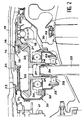
- FIG. 3 illustrates a first embodiment of the invention and first shows a modification of the joint holder sleeve, to which we have assigned here the reference 38 and which has a conical shape, the seal 39 sealing the side of the tree line to high pressure 16 now having a larger diameter important that seal 23, unchanged, assigned to the tightness of the side of the tree line at low pressure 15; the joint 39 does not rub on the line of trees 16 proper, but on a span sealing 41 of a spacer 40 integrated into the line high pressure shafts 16 and comprising for this purpose an abutment surface 42 threaded on said line of trees and compressed by the nut 19 between it and the crown 21.
- sealing surface 41 and the sleeve 38 surround the nut 19 instead of cover from the front and it becomes accessible by the rear, using a claw tool not shown, that you can slide in the meantime annular 43 between the tree lines 15 and 16, and that the nut 19 is at the anterior end of the line of trees 16, the lip 14 which it surrounded having has been replaced by sealing surface 41.
- the reference 44 is assigned to a brake part of nut 19, which has clutch teeth entering nut 19 and the outer shaft line 16 to prohibit any relative rotation when it is placed; it is in the form of a split ring and in one elastic material which allows to open it to put it in place.
- the assembly differs from that of figure 2. It is undertaken by fixing the housing 30, then consists in insert the pinion 20 fitted with the nearest bearing him (here 29) in the housing 30, to put it on a bearing surface 50 at the bottom of the housing 30, to be made slide the seal sleeve 38 over the pinion 20 and attach it to the housing 30.
- the ferrule 45 provided with the bearing away from pinion 20 (here the ball bearing 28) is then introduced into the bore of the housing 30 and around the hub 27 and the bearing 29.
- the bearing 28 is wearing a spacer ring 51 which ends up touching the other level 29 during this movement, pushes it back and raises the sprocket 20 as well.
- the flange 35 abuts against the housing 30, the pinion 20 meshes with the crown 21.
- the drive shaft 25 is finally installed.
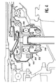
- Figure 4 shows a variant of this idea, where bearings 28 and 29 occupy the same places as in the previous design and where we find the shell 33; but the bearing stop flange 34 placed on the edge of the housing 30 is replaced by a collar 46 placed under it, as well as the flange 35 of the shell 33, with which it is in touch.
- the assembly is almost accomplished as previously, except that bearings 28 and 29 must both be put in place after the sprocket 20 has been placed in the housing 30.
Landscapes
- Engineering & Computer Science (AREA)
- Chemical & Material Sciences (AREA)
- Combustion & Propulsion (AREA)
- Mechanical Engineering (AREA)
- General Engineering & Computer Science (AREA)
- Mounting Of Bearings Or Others (AREA)
- Turbine Rotor Nozzle Sealing (AREA)
- General Details Of Gearings (AREA)
- Gear Transmission (AREA)
- Sealing Devices (AREA)
- Structures Of Non-Positive Displacement Pumps (AREA)
Abstract
Description
- la figure 1 déjà décrite est une vue générale d'une turbine à gaz ;
- la figure 2 représente un agencement antérieur à l'invention et où les problèmes d'accès à l'écrou évoqués plus haut ne sont pas résolus ;
- la figure 3 est une vue d'un agencement conforme à l'invention ; et
- la figure 4 est une vue d'un autre agencement conforme à l'invention.
Claims (4)
- Agencement comprenant une ligne d'arbres interne (15) et une ligne d'arbres externe (16) qui sont coaxiales, une partie antérieure (5) de la ligne d'arbres interne (15) dépassant d'une extrémité antérieure de la ligne d'arbres externe, un manchon (38) entourant les lignes d'arbres et portant deux joints d'étanchéité (23, 39) associés respectivement à elles, un palier (18) soutenant la ligne d'arbres externe près de l'extrémité antérieure et un écrou (19) de retenue du palier vissé autour de l'extrémité antérieure, caractérisé en ce qu'il comprend une entretoise (40) ayant une partie d'ajustement (42) glissée autour de la ligne d'arbres externe et enserrée entre l'écrou et le palier, et une partie d'étanchéité (41) disposée autour de l'écran et sur laquelle frotte le joint d'étanchéité (39) associé à la ligne d'arbres externe.
- Agencement selon la revendication 1, comprenant un pignon (20) de prise de mouvement disposé sous l'écrou (19), l'entretoise (40) et le manchon (38).
- Agencement selon la revendication 2, comprenant un boítier (30) de support du pignon entourant le pignon et un moyeu (27) du pignon et chargé de soutenir le pignon (20) verticalement, caractérisé en ce que le palier (28) est monté en passant par-dessous le boítier (30) et le manchon porte-joints (38) comprend une bride de fixation (47) au boítier butant contre le boítier (30) par l'arrière.
- Agencement selon la revendication 3, caractérisé en ce qu'il comprend une virole (45) unique, fixée au boítier (30), dans laquelle le palier (28) et un second palier (29), glissant verticalement, sont montés.
Applications Claiming Priority (2)
| Application Number | Priority Date | Filing Date | Title |
|---|---|---|---|
| FR0105900A FR2824362B1 (fr) | 2001-05-03 | 2001-05-03 | Agencement de montage de deux lignes d'arbre coaxiales |
| FR0105900 | 2001-05-03 |
Publications (2)
| Publication Number | Publication Date |
|---|---|
| EP1255023A1 true EP1255023A1 (fr) | 2002-11-06 |
| EP1255023B1 EP1255023B1 (fr) | 2005-12-21 |
Family
ID=8862927
Family Applications (1)
| Application Number | Title | Priority Date | Filing Date |
|---|---|---|---|
| EP02291097A Expired - Lifetime EP1255023B1 (fr) | 2001-05-03 | 2002-05-02 | Agencement de montage de deux lignes d'arbres coaxiales |
Country Status (8)
| Country | Link |
|---|---|
| US (2) | US20050100258A1 (fr) |
| EP (1) | EP1255023B1 (fr) |
| JP (1) | JP4172579B2 (fr) |
| CA (1) | CA2445770C (fr) |
| DE (1) | DE60208108T2 (fr) |
| FR (1) | FR2824362B1 (fr) |
| RU (1) | RU2295043C2 (fr) |
| WO (1) | WO2002090723A1 (fr) |
Cited By (3)
| Publication number | Priority date | Publication date | Assignee | Title |
|---|---|---|---|---|
| JP2005076637A (ja) * | 2003-09-02 | 2005-03-24 | General Electric Co <Ge> | 回転タービンシャフト間をシールするのを可能にする方法及び装置 |
| FR2882096A1 (fr) * | 2005-02-11 | 2006-08-18 | Snecma Moteurs Sa | Turbomoteur a double corps avec des moyens de prise de mouvement sur les rotors basse pression et haute pression, module de prise de mouvement pour le turbomoteur et procede de montage du turbomoteur |
| EP1911938A1 (fr) * | 2006-10-13 | 2008-04-16 | Snecma | Turboréacteur |
Families Citing this family (12)
| Publication number | Priority date | Publication date | Assignee | Title |
|---|---|---|---|---|
| GB0600172D0 (en) * | 2006-01-06 | 2006-02-15 | Rolls Royce Plc | A bearing race |
| FR2917783B1 (fr) * | 2007-06-25 | 2013-04-12 | Snecma | Systeme de liaison d'arbre moteur avec ecrou auto-extracteur |
| FR2920191B1 (fr) * | 2007-08-23 | 2013-11-22 | Snecma | Moteur a turbine a gaz avec moyen d'entrainement pour le boitier d'accessoires et procede de montage dudit moteur |
| FR2977635B1 (fr) * | 2011-07-04 | 2017-03-24 | Snecma | Dispositif d'arbre d'entrainement d'une turbomachine |
| US10001028B2 (en) * | 2012-04-23 | 2018-06-19 | General Electric Company | Dual spring bearing support housing |
| FR2990239B1 (fr) | 2012-05-02 | 2015-10-30 | Snecma | Procede de devissage avant d'un ecrou de liaison dans un turboreacteur a double corps, outillage de devissage |
| FR3007458B1 (fr) * | 2013-06-21 | 2017-11-10 | Snecma | Carter intermediaire ameliore de turbomachine et ensemble d'entrainement de boitier d'accessoire |
| ITTO20130636A1 (it) * | 2013-07-29 | 2015-01-30 | Avio Spa | Scatola di trasmissione, e metodo di smontaggio per disaccoppiare un albero di azionamento in tale scatola di trasmissione |
| BR112016024852B1 (pt) * | 2014-04-29 | 2022-10-11 | Safran Aircraft Engines | Conjunto modular para uma turbomáquina |
| EP3365960A4 (fr) * | 2015-10-22 | 2019-06-19 | Nidec Motor Corporation | Moteur électrique |
| RU2711895C2 (ru) * | 2017-06-19 | 2020-01-23 | Публичное акционерное общество "ОДК-Уфимское моторостроительное производственное объединение" | Двухконтурный турбореактивный двигатель |
| US11274605B2 (en) * | 2019-08-30 | 2022-03-15 | Rolls-Royce Corporation | System and method for shimming a bevel gear in an IGB on a gas turbine without removal of the bevel gear |
Citations (9)
| Publication number | Priority date | Publication date | Assignee | Title |
|---|---|---|---|---|
| FR935401A (fr) * | 1945-06-21 | 1948-06-18 | ||
| US2932443A (en) * | 1956-08-17 | 1960-04-12 | United Aircraft Corp | Accessory drive |
| GB1085619A (en) * | 1966-03-09 | 1967-10-04 | Rolls Royce | Gas turbine engine |
| GB1130279A (en) * | 1967-02-28 | 1968-10-16 | Rolls Royce | Bearing assembly |
| US4201426A (en) * | 1978-04-27 | 1980-05-06 | General Electric Company | Bearing clamping assembly for a gas turbine engine |
| FR2494342A1 (fr) * | 1980-11-20 | 1982-05-21 | Gen Electric | Boite d'engrenage d'entree perfectionnee |
| EP0359659A1 (fr) * | 1988-09-14 | 1990-03-21 | Societe Nationale D'etude Et De Construction De Moteurs D'aviation "Snecma" | Accouplement d'un arbre dans un support de palier de turbomachine et procédé de désaccouplage |
| US5201844A (en) * | 1991-09-09 | 1993-04-13 | General Electric Company | Rotor and bearing assembly |
| EP0987457A1 (fr) * | 1998-09-17 | 2000-03-22 | Societe Nationale D'etude Et De Construction De Moteurs D'aviation "Snecma" | Agencement de retenue d'un palier notamment pour un arbre de compresseur à haute pression |
Family Cites Families (4)
| Publication number | Priority date | Publication date | Assignee | Title |
|---|---|---|---|---|
| US4973221A (en) * | 1989-04-17 | 1990-11-27 | General Electric Company | Gas turbine engine motor assembly |
| SU1746013A1 (ru) * | 1990-06-22 | 1992-07-07 | Научно-исследовательский институт специального машиностроения при МГТУ им.Н.Э.Баумана | Система опор роторов газотурбинного двигател |
| RU2038513C1 (ru) * | 1992-03-06 | 1995-06-27 | Акционерное общество открытого типа "Авиадвигатель" | Узел межвальной опоры газотурбинного двигателя |
| FR2857708B1 (fr) * | 2003-07-15 | 2005-09-23 | Snecma Moteurs | Dispositif perfectionne de fixation d'un arbre de moteur sur un support de palier |
-
2001
- 2001-05-03 FR FR0105900A patent/FR2824362B1/fr not_active Expired - Fee Related
-
2002
- 2002-05-02 RU RU2003134961/06A patent/RU2295043C2/ru active
- 2002-05-02 WO PCT/FR2002/001506 patent/WO2002090723A1/fr not_active Ceased
- 2002-05-02 EP EP02291097A patent/EP1255023B1/fr not_active Expired - Lifetime
- 2002-05-02 US US10/476,372 patent/US20050100258A1/en not_active Abandoned
- 2002-05-02 DE DE60208108T patent/DE60208108T2/de not_active Expired - Lifetime
- 2002-05-02 JP JP2002587765A patent/JP4172579B2/ja not_active Expired - Lifetime
- 2002-05-02 CA CA002445770A patent/CA2445770C/fr not_active Expired - Lifetime
-
2005
- 2005-07-19 US US11/183,767 patent/US7341380B2/en not_active Expired - Lifetime
Patent Citations (9)
| Publication number | Priority date | Publication date | Assignee | Title |
|---|---|---|---|---|
| FR935401A (fr) * | 1945-06-21 | 1948-06-18 | ||
| US2932443A (en) * | 1956-08-17 | 1960-04-12 | United Aircraft Corp | Accessory drive |
| GB1085619A (en) * | 1966-03-09 | 1967-10-04 | Rolls Royce | Gas turbine engine |
| GB1130279A (en) * | 1967-02-28 | 1968-10-16 | Rolls Royce | Bearing assembly |
| US4201426A (en) * | 1978-04-27 | 1980-05-06 | General Electric Company | Bearing clamping assembly for a gas turbine engine |
| FR2494342A1 (fr) * | 1980-11-20 | 1982-05-21 | Gen Electric | Boite d'engrenage d'entree perfectionnee |
| EP0359659A1 (fr) * | 1988-09-14 | 1990-03-21 | Societe Nationale D'etude Et De Construction De Moteurs D'aviation "Snecma" | Accouplement d'un arbre dans un support de palier de turbomachine et procédé de désaccouplage |
| US5201844A (en) * | 1991-09-09 | 1993-04-13 | General Electric Company | Rotor and bearing assembly |
| EP0987457A1 (fr) * | 1998-09-17 | 2000-03-22 | Societe Nationale D'etude Et De Construction De Moteurs D'aviation "Snecma" | Agencement de retenue d'un palier notamment pour un arbre de compresseur à haute pression |
Cited By (8)
| Publication number | Priority date | Publication date | Assignee | Title |
|---|---|---|---|---|
| JP2005076637A (ja) * | 2003-09-02 | 2005-03-24 | General Electric Co <Ge> | 回転タービンシャフト間をシールするのを可能にする方法及び装置 |
| FR2882096A1 (fr) * | 2005-02-11 | 2006-08-18 | Snecma Moteurs Sa | Turbomoteur a double corps avec des moyens de prise de mouvement sur les rotors basse pression et haute pression, module de prise de mouvement pour le turbomoteur et procede de montage du turbomoteur |
| JP2006220153A (ja) * | 2005-02-11 | 2006-08-24 | Snecma | 低圧および高圧ロータに動力取り出し手段を有するツインスプールタービンエンジン、タービンエンジンのための動力取り出しモジュール、およびタービンエンジンを組み立てる方法 |
| EP1701019A1 (fr) * | 2005-02-11 | 2006-09-13 | Snecma | Turbomoteur à double corps avec des moyens de prise de mouvement sur les rotors basse pression et haute pression, module de prise de mouvement pour le turbomoteur et procédé de montage du turbomoteur |
| US7552591B2 (en) | 2005-02-11 | 2009-06-30 | Snecma | Twin spool turbine engine with power take-off means on the low-pressure and high-pressure rotors, and power take-off module for the turbine engine |
| EP1911938A1 (fr) * | 2006-10-13 | 2008-04-16 | Snecma | Turboréacteur |
| FR2907167A1 (fr) * | 2006-10-13 | 2008-04-18 | Snecma Sa | Arbre d'entrainement de boitier a engrenages de machines auxiliaires d'un turboreacteur; machine auxiliaire supplementaire modulaire |
| US8042341B2 (en) | 2006-10-13 | 2011-10-25 | Snecma | Turbojet engine accessory gear box driveshaft; modular additional accessory |
Also Published As
| Publication number | Publication date |
|---|---|
| DE60208108D1 (de) | 2006-01-26 |
| US20050249443A1 (en) | 2005-11-10 |
| JP4172579B2 (ja) | 2008-10-29 |
| RU2295043C2 (ru) | 2007-03-10 |
| US20050100258A1 (en) | 2005-05-12 |
| JP2004525298A (ja) | 2004-08-19 |
| FR2824362A1 (fr) | 2002-11-08 |
| CA2445770A1 (fr) | 2002-11-14 |
| RU2003134961A (ru) | 2005-05-10 |
| FR2824362B1 (fr) | 2003-09-05 |
| CA2445770C (fr) | 2009-12-15 |
| WO2002090723A1 (fr) | 2002-11-14 |
| DE60208108T2 (de) | 2006-08-31 |
| EP1255023B1 (fr) | 2005-12-21 |
| US7341380B2 (en) | 2008-03-11 |
Similar Documents
| Publication | Publication Date | Title |
|---|---|---|
| EP1255023B1 (fr) | Agencement de montage de deux lignes d'arbres coaxiales | |
| EP0387122B1 (fr) | Joint d'étanchéité d'arbre pour turbomachine | |
| CA2576701C (fr) | Systeme de liaison d'arbre moteur par ecrou escamotable | |
| FR2857708A1 (fr) | Dispositif perfectionne de fixation d'un arbre de moteur sur un support de palier | |
| EP0987457A1 (fr) | Agencement de retenue d'un palier notamment pour un arbre de compresseur à haute pression | |
| EP1564352A2 (fr) | Turboréacteur dont l'arbre d'entraínement de la soufflante est supporté par deux paliers | |
| FR2963062A1 (fr) | Assemblage entre un tourillon d'arbre de compresseur et un pignon conique pour l'entrainement d'un boitier d'accessoires d'une turbomachine | |
| FR2905153A1 (fr) | Systeme d'assemblage entre un tourillon et un element articule | |
| EP2978668A1 (fr) | Dispositif d'articulation à rotule pour la suspension d'une turbomachine a un pylone ou la suspension d'un equipement au corps de la turbomachine | |
| CA2838919C (fr) | Dispositif d'arbre d'entrainement d'une turbomachine | |
| EP3234311A1 (fr) | Système de réparation d'une attache équipant une paroi de réacteur | |
| FR2813227A1 (fr) | Systeme antivibratile sur un outil de travail tel qu'une debroussailleuse | |
| EP2414655A1 (fr) | Capot d'entree tournant pour turbomachine, comprenant une extremite avant excentree | |
| FR2586061A1 (fr) | Disque porte labyrinthe multifonction pour rotor de turbomachine | |
| WO2005089666A1 (fr) | Piece a main a usage dentaire ou chirurgical avec mecanisme de serrage | |
| FR2551651A1 (fr) | Piece a main de dentisterie et son embout porte-outil | |
| WO2015110751A1 (fr) | Disque de rotor a dispositif de prélèvement d'air centripète, compresseur comportant ledit disque et turbomachine avec un tel compresseur | |
| FR2712037A1 (fr) | Turbomachine à compresseur dont le rotor a un étage amont amovible. | |
| CA2587096C (fr) | Ensemble pour compresseur de moteur d'aeronef comprenant des aubes a attache marteau a pied incline | |
| FR2745235A1 (fr) | Accouplement en rotation d'une bride de roue a un organe de sortie d'un joint d'articulation d'une transmission | |
| FR3066534A1 (fr) | Ensemble pour turbomachine d'aeronef presentant un systeme de decouplage ameliore en cas de perte d'aube de soufflante | |
| EP3545609A1 (fr) | Ensemble de fixation d'un codeur sur une machine tournante | |
| FR2551383A1 (fr) | Procede et dispositif pour le surfacage d'une lentille optique a surface(s) de revolution | |
| EP0897075A1 (fr) | Agencement d'étanchéité pour un bout d'arbre | |
| FR2598460A1 (fr) | Dispositif pour supporter un element de rotation dans une machine de forage |
Legal Events
| Date | Code | Title | Description |
|---|---|---|---|
| PUAI | Public reference made under article 153(3) epc to a published international application that has entered the european phase |
Free format text: ORIGINAL CODE: 0009012 |
|
| 17P | Request for examination filed |
Effective date: 20020518 |
|
| AK | Designated contracting states |
Kind code of ref document: A1 Designated state(s): AT BE CH CY DE DK ES FI FR GB GR IE IT LI LU MC NL PT SE TR |
|
| AX | Request for extension of the european patent |
Free format text: AL;LT;LV;MK;RO;SI |
|
| AKX | Designation fees paid |
Designated state(s): DE FR GB |
|
| GRAP | Despatch of communication of intention to grant a patent |
Free format text: ORIGINAL CODE: EPIDOSNIGR1 |
|
| RAP1 | Party data changed (applicant data changed or rights of an application transferred) |
Owner name: SNECMA |
|
| GRAS | Grant fee paid |
Free format text: ORIGINAL CODE: EPIDOSNIGR3 |
|
| GRAA | (expected) grant |
Free format text: ORIGINAL CODE: 0009210 |
|
| AK | Designated contracting states |
Kind code of ref document: B1 Designated state(s): DE FR GB |
|
| REG | Reference to a national code |
Ref country code: GB Ref legal event code: FG4D Free format text: NOT ENGLISH |
|
| REF | Corresponds to: |
Ref document number: 60208108 Country of ref document: DE Date of ref document: 20060126 Kind code of ref document: P |
|
| GBT | Gb: translation of ep patent filed (gb section 77(6)(a)/1977) |
Effective date: 20060123 |
|
| PLBE | No opposition filed within time limit |
Free format text: ORIGINAL CODE: 0009261 |
|
| STAA | Information on the status of an ep patent application or granted ep patent |
Free format text: STATUS: NO OPPOSITION FILED WITHIN TIME LIMIT |
|
| 26N | No opposition filed |
Effective date: 20060922 |
|
| REG | Reference to a national code |
Ref country code: FR Ref legal event code: PLFP Year of fee payment: 15 |
|
| REG | Reference to a national code |
Ref country code: FR Ref legal event code: PLFP Year of fee payment: 16 |
|
| REG | Reference to a national code |
Ref country code: FR Ref legal event code: CD Owner name: SAFRAN AIRCRAFT ENGINES Effective date: 20170707 |
|
| REG | Reference to a national code |
Ref country code: FR Ref legal event code: PLFP Year of fee payment: 17 |
|
| PGFP | Annual fee paid to national office [announced via postgrant information from national office to epo] |
Ref country code: DE Payment date: 20210421 Year of fee payment: 20 Ref country code: FR Payment date: 20210421 Year of fee payment: 20 |
|
| PGFP | Annual fee paid to national office [announced via postgrant information from national office to epo] |
Ref country code: GB Payment date: 20210422 Year of fee payment: 20 |
|
| REG | Reference to a national code |
Ref country code: DE Ref legal event code: R071 Ref document number: 60208108 Country of ref document: DE |
|
| REG | Reference to a national code |
Ref country code: GB Ref legal event code: PE20 Expiry date: 20220501 |
|
| PG25 | Lapsed in a contracting state [announced via postgrant information from national office to epo] |
Ref country code: GB Free format text: LAPSE BECAUSE OF EXPIRATION OF PROTECTION Effective date: 20220501 |