EP1254818A2 - Dispositif de commande électrique, notamment pour frein de stationnement de véhicule automobile - Google Patents
Dispositif de commande électrique, notamment pour frein de stationnement de véhicule automobile Download PDFInfo
- Publication number
- EP1254818A2 EP1254818A2 EP02291113A EP02291113A EP1254818A2 EP 1254818 A2 EP1254818 A2 EP 1254818A2 EP 02291113 A EP02291113 A EP 02291113A EP 02291113 A EP02291113 A EP 02291113A EP 1254818 A2 EP1254818 A2 EP 1254818A2
- Authority
- EP
- European Patent Office
- Prior art keywords
- lever
- stationary guide
- handle
- bistable mechanism
- bistable
- Prior art date
- Legal status (The legal status is an assumption and is not a legal conclusion. Google has not performed a legal analysis and makes no representation as to the accuracy of the status listed.)
- Withdrawn
Links
Images


Classifications
-
- B—PERFORMING OPERATIONS; TRANSPORTING
- B60—VEHICLES IN GENERAL
- B60T—VEHICLE BRAKE CONTROL SYSTEMS OR PARTS THEREOF; BRAKE CONTROL SYSTEMS OR PARTS THEREOF, IN GENERAL; ARRANGEMENT OF BRAKING ELEMENTS ON VEHICLES IN GENERAL; PORTABLE DEVICES FOR PREVENTING UNWANTED MOVEMENT OF VEHICLES; VEHICLE MODIFICATIONS TO FACILITATE COOLING OF BRAKES
- B60T7/00—Brake-action initiating means
- B60T7/02—Brake-action initiating means for personal initiation
- B60T7/08—Brake-action initiating means for personal initiation hand actuated
- B60T7/085—Brake-action initiating means for personal initiation hand actuated by electrical means, e.g. travel, force sensors
-
- B—PERFORMING OPERATIONS; TRANSPORTING
- B60—VEHICLES IN GENERAL
- B60T—VEHICLE BRAKE CONTROL SYSTEMS OR PARTS THEREOF; BRAKE CONTROL SYSTEMS OR PARTS THEREOF, IN GENERAL; ARRANGEMENT OF BRAKING ELEMENTS ON VEHICLES IN GENERAL; PORTABLE DEVICES FOR PREVENTING UNWANTED MOVEMENT OF VEHICLES; VEHICLE MODIFICATIONS TO FACILITATE COOLING OF BRAKES
- B60T7/00—Brake-action initiating means
- B60T7/02—Brake-action initiating means for personal initiation
- B60T7/08—Brake-action initiating means for personal initiation hand actuated
-
- B—PERFORMING OPERATIONS; TRANSPORTING
- B60—VEHICLES IN GENERAL
- B60T—VEHICLE BRAKE CONTROL SYSTEMS OR PARTS THEREOF; BRAKE CONTROL SYSTEMS OR PARTS THEREOF, IN GENERAL; ARRANGEMENT OF BRAKING ELEMENTS ON VEHICLES IN GENERAL; PORTABLE DEVICES FOR PREVENTING UNWANTED MOVEMENT OF VEHICLES; VEHICLE MODIFICATIONS TO FACILITATE COOLING OF BRAKES
- B60T13/00—Transmitting braking action from initiating means to ultimate brake actuator with power assistance or drive; Brake systems incorporating such transmitting means, e.g. air-pressure brake systems
- B60T13/74—Transmitting braking action from initiating means to ultimate brake actuator with power assistance or drive; Brake systems incorporating such transmitting means, e.g. air-pressure brake systems with electrical assistance or drive
- B60T13/746—Transmitting braking action from initiating means to ultimate brake actuator with power assistance or drive; Brake systems incorporating such transmitting means, e.g. air-pressure brake systems with electrical assistance or drive and mechanical transmission of the braking action
-
- B—PERFORMING OPERATIONS; TRANSPORTING
- B60—VEHICLES IN GENERAL
- B60T—VEHICLE BRAKE CONTROL SYSTEMS OR PARTS THEREOF; BRAKE CONTROL SYSTEMS OR PARTS THEREOF, IN GENERAL; ARRANGEMENT OF BRAKING ELEMENTS ON VEHICLES IN GENERAL; PORTABLE DEVICES FOR PREVENTING UNWANTED MOVEMENT OF VEHICLES; VEHICLE MODIFICATIONS TO FACILITATE COOLING OF BRAKES
- B60T7/00—Brake-action initiating means
- B60T7/02—Brake-action initiating means for personal initiation
- B60T7/08—Brake-action initiating means for personal initiation hand actuated
- B60T7/10—Disposition of hand control
- B60T7/102—Disposition of hand control by means of a tilting lever
- B60T7/104—Disposition of hand control by means of a tilting lever with a locking mechanism
- B60T7/105—Disposition of hand control by means of a tilting lever with a locking mechanism the lock being released by means of a push button
-
- B—PERFORMING OPERATIONS; TRANSPORTING
- B60—VEHICLES IN GENERAL
- B60T—VEHICLE BRAKE CONTROL SYSTEMS OR PARTS THEREOF; BRAKE CONTROL SYSTEMS OR PARTS THEREOF, IN GENERAL; ARRANGEMENT OF BRAKING ELEMENTS ON VEHICLES IN GENERAL; PORTABLE DEVICES FOR PREVENTING UNWANTED MOVEMENT OF VEHICLES; VEHICLE MODIFICATIONS TO FACILITATE COOLING OF BRAKES
- B60T7/00—Brake-action initiating means
- B60T7/02—Brake-action initiating means for personal initiation
- B60T7/08—Brake-action initiating means for personal initiation hand actuated
- B60T7/10—Disposition of hand control
- B60T7/107—Disposition of hand control with electrical power assistance
-
- F—MECHANICAL ENGINEERING; LIGHTING; HEATING; WEAPONS; BLASTING
- F16—ENGINEERING ELEMENTS AND UNITS; GENERAL MEASURES FOR PRODUCING AND MAINTAINING EFFECTIVE FUNCTIONING OF MACHINES OR INSTALLATIONS; THERMAL INSULATION IN GENERAL
- F16D—COUPLINGS FOR TRANSMITTING ROTATION; CLUTCHES; BRAKES
- F16D65/00—Parts or details
- F16D65/14—Actuating mechanisms for brakes; Means for initiating operation at a predetermined position
-
- G—PHYSICS
- G05—CONTROLLING; REGULATING
- G05G—CONTROL DEVICES OR SYSTEMS INSOFAR AS CHARACTERISED BY MECHANICAL FEATURES ONLY
- G05G5/00—Means for preventing, limiting or returning the movements of parts of a control mechanism, e.g. locking controlling member
- G05G5/005—Means for preventing, limiting or returning the movements of parts of a control mechanism, e.g. locking controlling member for preventing unintentional use of a control mechanism
-
- F—MECHANICAL ENGINEERING; LIGHTING; HEATING; WEAPONS; BLASTING
- F16—ENGINEERING ELEMENTS AND UNITS; GENERAL MEASURES FOR PRODUCING AND MAINTAINING EFFECTIVE FUNCTIONING OF MACHINES OR INSTALLATIONS; THERMAL INSULATION IN GENERAL
- F16D—COUPLINGS FOR TRANSMITTING ROTATION; CLUTCHES; BRAKES
- F16D2121/00—Type of actuator operation force
- F16D2121/18—Electric or magnetic
- F16D2121/24—Electric or magnetic using motors
-
- G—PHYSICS
- G05—CONTROLLING; REGULATING
- G05G—CONTROL DEVICES OR SYSTEMS INSOFAR AS CHARACTERISED BY MECHANICAL FEATURES ONLY
- G05G1/00—Controlling members, e.g. knobs or handles; Assemblies or arrangements thereof; Indicating position of controlling members
- G05G1/02—Controlling members for hand actuation by linear movement, e.g. push buttons
Definitions
- the invention relates to an electrical control device, in particular for a parking brake in a vehicle automotive, which includes a mounted actuator movable in a stationary guide, back and forth in a first direction under the action of a return spring and in a opposite direction under manual action, and means of joystick stroke detection providing a signal corresponding to a processing and control unit, and manually operated locking / unlocking means, for lock the movable lever in relation to the stationary guide and the unlock vis-à-vis it.
- Another important aspect when designing electric control devices for such brakes electric parking is to guarantee security against an unexpected release of the parking brake, for example when an unauthorized person initiates this release by fault.
- the locking means comprise push button carried by the movable joystick and cooperating with a bistable mechanism ensuring the locking of the lever in its position when the bistable mechanism is first actuated, and ensuring the release of the joystick from its position during a new actuation of the bistable mechanism.
- the control device 10 illustrated in perspective in as a whole in FIG. 1, comprises a lever 12, essentially composed of an actuating part 14 and a frame 16 of flattened shape and substantially rectangular, and a guide 18, generally U-shaped, such as the frame 16 of handle 12 moves there in the manner of a drawer. More specifically, the frame 16 comprises two sides or uprights longitudinal 20 and 22 and two sides or transverse uprights 24 and 26. The actuating part 14 of the handle 12 is fixed to the transverse upright 24, and we can even predict that these two elements are one piece.
- the guide 18 comprises two arms 28 and 30, which form the two sides of the U-shape, and a crosspiece 32 which forms the background.
- the longitudinal uprights 20 and 22 of the frame 16 slide along the arms 28 and 30 of the guide 18 back and forth along a general longitudinal axis X-X, so that the transverse upright 26 of the lever 12 moves away or approaches the crosspiece 32 of guide 18.
- a threaded stud 34 On the transverse upright 26 of the frame 16 of the lever 12 is fixed a threaded stud 34, oriented along the axis X-X, which passes through freely a hole 36 of the crosspiece 32 of the guide 18.
- a nut / lock nut group 40 On the end 38 of the stud 34 is fixed a nut / lock nut group 40, and a return spring 42 is held captive between the group nut / against nut 40 and cross member 32 of the guide.
- the actuating part 14 of the handle 12 is conformed on one of its sides, and preferably on its side lower, so as to present a spout 44, as can be grip handle 12 with the fingers of one hand, folding them up slightly around the spout 44, and pull it by compressing the spring return 42 in the direction of the X-X axis to the right in Figure 1.
- the frame 16 of the lever 12 carries a finger 52 which attacks the cursor of a potentiometer 56 fixed on the stationary guide 18.
- the displacements of the frame 16 are thus transformed into cursor movements and correlative variations of the resistance across potentiometer 56, and this information is sent to a processing and control unit (not shown) which uses it to control the parking brake of the vehicle in which the control device 10 described here.
- the control device 10 also comprises a locking / unlocking device 58 which will now be described.
- the actuating part 14 of the handle 12 comprises a housing 60 which receives a push button 62 capable of being there move, also in the direction of the X-X axis, over a short distance against a return spring 64.
- the push button 62 carries a rod 66 which protrudes inside the frame 16 of the lever 12 and the inner end 68 of the rod 66 here cooperates with a bistable mechanism 70, also called mechanism “push-on / push-off", or "push / push” in evocation to his operating mode.
- This mechanism is mounted on a transverse beam 72 which crosses the frame 16 substantially in the middle, and it comprises a input member 74 attacked by the rod 66 of the push button 62, and an outlet member 76, in the form of a shaft arranged along the X-X axis and rotatably mounted in two bearings 78 and 80, one in the beam 72 and the other in the transverse upright 26 of the frame 16.
- the shaft 76 carries a circular and free rack in rotation 82 in the area between the two bearings 78 and 80.
- latches 84 and 86 are mounted in frame 16 of on either side of the tree 76. As these two latches are symmetrical about the X-X axis, we will just describe latch 84. It is in the form of a shaped plate circle or disc sector, around an axis Y-Y perpendicular to the axis X-X of the lever 12, and spaced therefrom.
- the latch 84 On its convex side in the sector of a circle, the latch 84 has a toothing 88 which meshes with the rack tree 82 circular 76.
- the side 90 of the latch opposite the mechanism 70 carries a lateral lug 92 which, following a rotation of the latch 84 around the Y-Y axis, generally moves away from the X-X axis and perpendicular to the longitudinal upright 20 of the frame 16, that it crosses without hindrance through an opening 94.
- the arm 28 of the guide 18 comprises several lights 96, here four in number, and when the rotation of the latch 84 continues, the lug 92 comes to engage in one of these lights, depending on the axial position momentarily occupied by frame 16.
- the mechanism 70 is such that an action on the button 62, that is to say a depression against the spring 64 followed by a release of button 62, results in a 1/4 rotation of rotation of the output member / shaft 76 in one direction. A new action (push / release) on push button 62 will result by a 1/4 turn of the shaft 76 in the direction opposite.
- a switch 98 is associated with the mechanism 70.
- Switch 98 can be connected to the control unit processing and control previously mentioned, in particular for signaling or warning purposes.
- a lamp is provided in the form of a light-emitting diode 100 ( Figure 3) housed in button 62 and powered via the switch 98, in order to indicate the state of the mechanism 70, and consequently the state of the locking / unlocking mechanism 58.
- the pitch of the rack 82 and that of the toothing 88 are thus chosen so that this 1/4 turn rotation of the shaft 76 results in a rotation of the latch 84 around the Y-Y axis, by a sufficient angle either to bring the lug 92 into engagement in a light 96, or to bring the lug 92 out of the light 96 in which he was.
- FIG. 3 we have shown schematically that the entire device 10 is fixed to the vehicle structure, here symbolized by a support leg 102, inside the dashboard and at the bottom of it, so that, in the rest position, the handle 14 and the button 62 are substantially flush with the covering of the dashboard, here symbolized by the reference 104.
- the angular position of the shaft 76 at the outlet of the push-push mechanism 70 is such that latches 84 and 86 are turned towards lever 12, that their side 90 is distant from the longitudinal upright 20, or 22 of the frame 16, and that their lug 92 is released from the lights 96 of the arms 28 and 30.
- the switch 98 is open and the diode 100 is off.
- the sliders of potentiometers 56 are at one end of their stroke, and the corresponding signal is evaluated in the brake processing and control unit as indicating "no braking".
- the assembly lever 14-cage 16 remains blocked relative to the guide 18 in this position, and the parking brake remains applied under the corresponding application force. According to the traction that has been exerted by the driver on the lever 14, and therefore according to the race imposed on it, the lug 92 will engage in a light 96 more or less distant from the crosspiece 32 of the guide 18, and the application force of the parking brake will be different.
- lug 92 is not exactly facing a light 96, it is planned to form the lug 92 with one end rounded, which will initiate its entry into the light 96 most neighbor. The full entry of ergot 92 into the light will take place when the driver releases the lever 14, that he has indeed no longer need to remember since the engagement of lug 92 in light 96 prevents return of the joystick assembly 14-cage16 to the left.
- the driver To release the parking brake, the driver must combine two actions: first, he must shoot the lever 14, again by gripping its beak 44, then actuating again the push button 62.
- this new action on the push button 62 triggers the push-push 70 mechanism which rotates shaft 76 1/4 turn in opposite direction, resulting in a pivoting of the latches 84 and 86 in return, and an outlet of the lug 92 out of the light 96.
- the diode 100 goes out.
- the driver releases lever 14 which returns to its position substantially flush with the casing 104 of the switchboard edge, and the entire device 10 is returned to its position of rest.
- the entire system presents a particularly ergonomic layout.
- traction on the joystick 14 will take place in a physiologically natural direction.
- the traction on the lever 14 will mobilize only the four fingers from index finger to little finger, and the driver has still with his thumb in order to push the push button 62, also in a natural physiological direction.
- All the necessary parts can be manufactured at reasonable costs, all the more so as guiding the frame 16 in length in guide 18 is relatively insensitive to tolerances.
- the reliability of the device is in particular excellent thanks to the realization substantially symmetrical with respect to the axis longitudinal X-X, which makes it little prone to jamming.
- Adaptation to various vehicle models is possible in a very simple way. It is enough to realize, from a model of unique mechanism, each time a joystick group 14 - push button 62 whose shapes, materials, and colors are adapted to that of the dashboard trim 104 of the vehicle concerned. If necessary, the adaptation may concern the return spring 42, either that it is replaced by another, or that its calibration is modified using the nut / lock nut group 40.
Landscapes
- Engineering & Computer Science (AREA)
- Mechanical Engineering (AREA)
- Transportation (AREA)
- General Engineering & Computer Science (AREA)
- Physics & Mathematics (AREA)
- General Physics & Mathematics (AREA)
- Automation & Control Theory (AREA)
- Mechanical Control Devices (AREA)
- Regulating Braking Force (AREA)
Abstract
Description
- le mécanisme bistable est un mécanisme du type "push-on/push-off" ;
- le mécanisme bistable comprend un organe d'entrée susceptible d'effectuer des mouvements en va-et-vient dans une direction longitudinale du dispositif et un organe de sortie susceptible d'effectuer des mouvements de rotation dans un sens et dans l'autre autour de cet axe longitudinal ;
- l'organe de sortie du mécanisme bistable est susceptible d'effectuer des mouvements de 1/4 de tour dans un sens et dans l'autre ;
- les moyens de blocage/déblocage comprennent au moins un loquet commandé par l'organe de sortie du mécanisme bistable ;
- le loquet est une plaque en forme de secteur de cercle autour d'un axe perpendiculaire à l'axe longitudinal du dispositif et écarté de celui-ci, le loquet comportant une denture en secteur de cercle en engrènement avec une crémaillère portée par l'organe de sortie du mécanisme bistable autour de l'axe longitudinal ;
- le loquet comporte un ergot dirigé sensiblement en éloignement de l'axe longitudinal, et le guide stationnaire comporte au moins une lumière dans laquelle peut venir s'engager l'ergot ;
- la manette comprend une partie d'actionnement destinée à être actionnée à la main, un cadre de forme générale aplatie et rectangulaire, solidaire de la partie d'actionnement, et un goujon solidaire du cadre et dirigé à l'opposé de la partie d'actionnement dans la direction de l'axe, et il est prévu un ressort de rappel interposé entre le goujon et une traverse du guide stationnaire ;
- le guide stationnaire comprend deux bras longitudinaux portés par la traverse à la manière des bras d'un U, assurant un guidage pour deux côtés longitudinaux du cadre de la manette ;
- il est prévu un commutateur actionné par le mécanisme bistable ;
- il est prévu une diode électroluminescente dans le bouton-poussoir, raccordée électriquement au commutateur ;
- le guide stationnaire est destiné à être fixé à la structure d'un véhicule et à l'intérieur du tableau de bord de celui-ci, de manière que la partie d'actionnement de la manette et le bouton-poussoir soient sensiblement en affleurement avec un habillage du tableau de bord ;
- la manette porte un doigt attaquant un curseur d'un potentiomètre fixé sur le guide stationnaire et susceptible d'être raccordé à une unité de traitement et de commande de freinage ;
- la partie d'actionnement de la manette comporte un bec conformé de manière à être saisi avec les doigts repliés d'une main ;
- la ou les lumières(s) est(sont) ménagée(s) dans une plaquette séparée rapportée par fixation sur le guide stationnaire ;
- il est prévu deux loquets sensiblement symétriques par rapport à l'axe longitudinal du dispositif.
- la figure 1 est une vue en perspective d'un dispositif de commande selon l'invention ;
- la figure 2 est une vue de dessus et avec arrachements partiels du dispositif de la figure 1 ; et
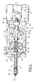
- la figure 3 est une vue, sensiblement coupe longitudinale, du dispositif des figures 1 et 2.
Claims (16)
- Dispositif de commande électrique (10), notamment pour frein de stationnement de véhicule automobile, comprenant une manette d'actionnement (12) montée mobile dans un guide stationnaire (18) en va-et-vient dans une première direction sous l'action d'un ressort de rappel (42) et dans une direction opposée sous une action manuelle, des moyens de détection (52, 56) de la course de la manette (12) et fournissant un signal correspondant à une unité de traitement et de commande, et des moyens de blocage/déblocage (58) à actionnement manuel, destinés à bloquer la manette mobile (12) par rapport au guide stationnaire (18) et à la débloquer vis-à-vis de celui-ci,
caractérisé en ce que les moyens de blocage (58) comprennent un bouton-poussoir (62) porté par la manette (12) mobile et coopérant avec un mécanisme bistable (70) assurant le blocage de la manette (12) dans sa position lors d'un premier actionnement du mécanisme bistable, et assurant le déblocage de la manette depuis sa position lors d'un nouvel actionnement du mécanisme bistable. - Dispositif selon la revendication 1, caractérisé en ce que le mécanisme bistable (70) est un mécanisme du type "push on-push off".
- Dispositif selon la revendication 2, caractérisé en ce que le mécanisme bistable (70) comprend un organe d'entrée (74) susceptible d'effectuer des mouvements en va-et-vient dans une direction longitudinale (X-X) du dispositif (10) et un organe de sortie (76) susceptible d'effectuer des mouvements de rotation dans un sens et dans l'autre autour de cet axe longitudinal (X-X).
- Dispositif selon la revendication 3, caractérisé en ce que l'organe de sortie (76) du mécanisme bistable (70) est susceptible d'effectuer des mouvements de 1/4 de tour dans un sens et dans l'autre.
- Dispositif selon l'une ou l'autre des revendications 3 et 4, caractérisé en ce que les moyens de blocage/déblocage (58) comprennent au moins un loquet (84, 86) commandé par l'organe de sortie (76) du mécanisme bistable (70).
- Dispositif selon la revendication 5, caractérisé en ce que le loquet (84, 86) est une plaquette en forme de secteur de cercle autour d'un axe (Y-Y) perpendiculaire à l'axe longitudinal (X-X) du dispositif (10) et écarté de celui-ci, le loquet (84, 86) comportant une denture (88) en secteur de cercle en engrènement avec une crémaillère (82) portée par l'organe de sortie (76) du mécanisme bistable (70) autour de l'axe longitudinal (X-X).
- Dispositif selon la revendication 6, caractérisé en ce que le loquet (84) comporte un ergot (92) dirigé sensiblement en éloignement de l'axe longitudinal (X-X), et en ce que le guide stationnaire (18) comporte au moins une lumière (96) dans laquelle peut venir s'engager l'ergot (92).
- Dispositif selon l'une quelconque des revendications précédentes, caractérisé en ce que la manette (12) comprend une partie d'actionnement (14) destinée à être actionnée à la main, un cadre (16) de forme générale aplatie et rectangulaire, solidaire de la partie d'actionnement (14), et un goujon (34) solidaire du cadre (16) et dirigé à l'opposé de la partie d'actionnement (14) dans la direction de l'axe (X-X), et en ce qu'il est prévu un ressort de rappel (42) interposé entre le goujon (34) et une traverse (32) du guide stationnaire (18).
- Dispositif selon la revendication 8, caractérisé en ce que le guide stationnaire (18) comprend deux bras longitudinaux (28, 30) portés par la traverse (32) à la manière des bras d'un U, assurant un guidage pour deux côtés longitudinaux (20, 22) du cadre (16) de la manette (12).
- Dispositif selon l'une quelconque des revendications précédentes, caractérisé en ce qu'il est prévu un commutateur (98) actionné par le mécanisme bistable (70).
- Dispositif selon la revendication 10, caractérisé en ce qu'il est prévu une diode électroluminescente (100) dans le bouton-poussoir (62), raccordée électriquement au commutateur (98).
- Dispositif selon l'une quelconque des revendications précédentes, caractérisé en ce que le guide stationnaire (18) est destiné à être fixé (102) à la structure d'un véhicule et à l'intérieur du tableau de bord de celui-ci, de manière que la partie d'actionnement (14) de la manette (12) et le bouton-poussoir (62) soient sensiblement en affleurement avec un habillage (104) du tableau de bord.
- Dispositif selon l'une quelconque des revendications précédentes, caractérisé en ce que la manette (12) porte un doigt (52) attaquant un curseur d'un potentiomètre (56) fixé sur le guide stationnaire (18) et susceptible d'être raccordé à une unité de traitement et de commande de freinage.
- Dispositif selon l'une quelconque des revendications précédentes, caractérisé en ce que la partie d'actionnement (14) de la manette (12) comporte un bec (44) conformé de manière à être saisi avec les doigts repliés d'une main.
- Dispositif selon la revendication 7, caractérisé en ce que la ou les lumières(s) est(sont) ménagée(s) dans une plaquette (106) séparée rapportée par fixation sur le guide stationnaire (18).
- Dispositif selon la revendication 5, ou l'une au moins des revendications qui en dépendent, caractérisé en ce qu'il est prévu deux loquets (84, 86) sensiblement symétriques par rapport à l'axe longitudinal (X-X) du dispositif (10).
Applications Claiming Priority (2)
| Application Number | Priority Date | Filing Date | Title |
|---|---|---|---|
| FR0105956 | 2001-05-04 | ||
| FR0105956A FR2824304B1 (fr) | 2001-05-04 | 2001-05-04 | Dispositif de commande electrique, notamment pour frein de stationnement de vehicule automobile |
Publications (2)
| Publication Number | Publication Date |
|---|---|
| EP1254818A2 true EP1254818A2 (fr) | 2002-11-06 |
| EP1254818A3 EP1254818A3 (fr) | 2002-12-04 |
Family
ID=8862964
Family Applications (1)
| Application Number | Title | Priority Date | Filing Date |
|---|---|---|---|
| EP02291113A Withdrawn EP1254818A3 (fr) | 2001-05-04 | 2002-05-03 | Dispositif de commande électrique, notamment pour frein de stationnement de véhicule automobile |
Country Status (2)
| Country | Link |
|---|---|
| EP (1) | EP1254818A3 (fr) |
| FR (1) | FR2824304B1 (fr) |
Family Cites Families (2)
| Publication number | Priority date | Publication date | Assignee | Title |
|---|---|---|---|---|
| DE19718679A1 (de) * | 1997-05-02 | 1998-11-05 | Itt Mfg Enterprises Inc | Betätigungsvorrichtung für eine elektrische Fremdkraftfeststellbremsanlage |
| FR2793203B1 (fr) * | 1999-05-07 | 2001-06-01 | Renault | Procede et dispositif de commande de frein a main electrique |
-
2001
- 2001-05-04 FR FR0105956A patent/FR2824304B1/fr not_active Expired - Fee Related
-
2002
- 2002-05-03 EP EP02291113A patent/EP1254818A3/fr not_active Withdrawn
Also Published As
| Publication number | Publication date |
|---|---|
| EP1254818A3 (fr) | 2002-12-04 |
| FR2824304A1 (fr) | 2002-11-08 |
| FR2824304B1 (fr) | 2003-07-18 |
Similar Documents
| Publication | Publication Date | Title |
|---|---|---|
| FR3060630B1 (fr) | Commande d'ouverture affleurante a ejection et retraction mecanique ou electrique. | |
| EP1111171B2 (fr) | Système de sécurité d'un ouvrant de véhicule automobile équipé de commutateurs sans actionnement mécanique | |
| EP0274287B1 (fr) | Serrure, notamment pour porte de véhicule automobile | |
| FR2737906A1 (fr) | Fermeture de vehicule automobile | |
| FR2704266A1 (fr) | Fermeture de porte pour véhicules automobiles avec système de verrouillage protège-enfants. | |
| FR2681896A1 (fr) | Dispositif de blocage pour portes d'un vehicule a moteur pouvant etre ouvertes aussi bien de l'exterieur que de l'interieur, ou bien ne pouvant etre ouvertes ni de l'exterieur, ni de l'interieur. | |
| EP1111165A1 (fr) | Poignée d'ouvrant de véhicule automobile comportant des moyens perfectionnés d'actionnement des organes de commutation | |
| FR2852993A1 (fr) | Serrure pour ouvrant de vehicule automobile, a memorisation de decondamnation/condamnation | |
| FR2488645A2 (fr) | Agencement de fermeture a commande centrale destine aux portes d'un vehicule automobile | |
| FR2606448A1 (fr) | Serrure actionnee electriquement pour vehicule | |
| FR2641312A1 (fr) | Mecanisme pour portes tournantes basculantes | |
| FR2886756A1 (fr) | Dispositif d'actionnement d'un appareil electrique interrupteur avec dispositif de verrouillage | |
| FR2639144A1 (fr) | Mecanisme a serrure pour contacteur-limiteur | |
| EP1004730B1 (fr) | Serrure pour portière avant ou arrière de véhicule automobile | |
| FR2575434A1 (fr) | Dispositif de commande, notamment pour derailleur de cycle | |
| FR2724688A1 (fr) | Fermeture de porte pour vehicules automobiles avec systeme de securite protege-enfants | |
| EP1254818A2 (fr) | Dispositif de commande électrique, notamment pour frein de stationnement de véhicule automobile | |
| FR2659790A1 (fr) | Dispositif de commande pour des elements a glissiere d'un vehicule pouvant etre actionne depuis l'exterieur du vehicule. | |
| EP0989265B1 (fr) | Serrure simplifiée pour portière de vèhicule automobile | |
| EP1655190B1 (fr) | Commande à retour d'effort de frein secondaire électrique de véhicule automobile | |
| EP0906997A1 (fr) | Dispositif de verrouillage comportant un objet de transmission commandé par came | |
| EP0989266B1 (fr) | Serrure à décondamnation automatique à l'ouverture | |
| FR2614597A1 (fr) | Dispositif pour actionner le changement de vitesses d'une bicyclette | |
| FR2880852A1 (fr) | Boite a gants de vehicule automobile | |
| EP1393336B1 (fr) | Dispositif de commande pour vehicule automobile destine notamment a piloter un ordinateur de bord |
Legal Events
| Date | Code | Title | Description |
|---|---|---|---|
| PUAI | Public reference made under article 153(3) epc to a published international application that has entered the european phase |
Free format text: ORIGINAL CODE: 0009012 |
|
| PUAL | Search report despatched |
Free format text: ORIGINAL CODE: 0009013 |
|
| AK | Designated contracting states |
Kind code of ref document: A2 Designated state(s): AT BE CH CY DE DK ES FI FR GB GR IE IT LI LU MC NL PT SE TR |
|
| AX | Request for extension of the european patent |
Free format text: AL;LT;LV;MK;RO;SI |
|
| AK | Designated contracting states |
Kind code of ref document: A3 Designated state(s): AT BE CH CY DE DK ES FI FR GB GR IE IT LI LU MC NL PT SE TR |
|
| AX | Request for extension of the european patent |
Free format text: AL;LT;LV;MK;RO;SI |
|
| AKX | Designation fees paid | ||
| RBV | Designated contracting states (corrected) |
Designated state(s): BE DE ES GB |
|
| REG | Reference to a national code |
Ref country code: DE Ref legal event code: 8566 |
|
| 17P | Request for examination filed |
Effective date: 20030527 |
|
| GRAP | Despatch of communication of intention to grant a patent |
Free format text: ORIGINAL CODE: EPIDOSNIGR1 |
|
| RTI1 | Title (correction) |
Free format text: ELECTRICAL INITIATION MEANS FOR A VEHICLE PARKING BRAKE |
|
| STAA | Information on the status of an ep patent application or granted ep patent |
Free format text: STATUS: THE APPLICATION IS DEEMED TO BE WITHDRAWN |
|
| 18D | Application deemed to be withdrawn |
Effective date: 20080904 |