EP1254018B1 - Method and apparatus for automatically detaching the supporting fabric from an elastomeric band - Google Patents
Method and apparatus for automatically detaching the supporting fabric from an elastomeric band Download PDFInfo
- Publication number
- EP1254018B1 EP1254018B1 EP00981348A EP00981348A EP1254018B1 EP 1254018 B1 EP1254018 B1 EP 1254018B1 EP 00981348 A EP00981348 A EP 00981348A EP 00981348 A EP00981348 A EP 00981348A EP 1254018 B1 EP1254018 B1 EP 1254018B1
- Authority
- EP
- European Patent Office
- Prior art keywords
- rollers
- roller
- supporting
- elongated piece
- piece
- Prior art date
- Legal status (The legal status is an assumption and is not a legal conclusion. Google has not performed a legal analysis and makes no representation as to the accuracy of the status listed.)
- Expired - Lifetime
Links
Images


Classifications
-
- B—PERFORMING OPERATIONS; TRANSPORTING
- B29—WORKING OF PLASTICS; WORKING OF SUBSTANCES IN A PLASTIC STATE IN GENERAL
- B29D—PRODUCING PARTICULAR ARTICLES FROM PLASTICS OR FROM SUBSTANCES IN A PLASTIC STATE
- B29D30/00—Producing pneumatic or solid tyres or parts thereof
- B29D30/06—Pneumatic tyres or parts thereof (e.g. produced by casting, moulding, compression moulding, injection moulding, centrifugal casting)
- B29D30/52—Unvulcanised treads, e.g. on used tyres; Retreading
-
- B—PERFORMING OPERATIONS; TRANSPORTING
- B29—WORKING OF PLASTICS; WORKING OF SUBSTANCES IN A PLASTIC STATE IN GENERAL
- B29D—PRODUCING PARTICULAR ARTICLES FROM PLASTICS OR FROM SUBSTANCES IN A PLASTIC STATE
- B29D30/00—Producing pneumatic or solid tyres or parts thereof
- B29D30/06—Pneumatic tyres or parts thereof (e.g. produced by casting, moulding, compression moulding, injection moulding, centrifugal casting)
- B29D30/38—Textile inserts, e.g. cord or canvas layers, for tyres; Treatment of inserts prior to building the tyre
- B29D30/44—Stretching or treating the layers before application on the drum
-
- Y—GENERAL TAGGING OF NEW TECHNOLOGICAL DEVELOPMENTS; GENERAL TAGGING OF CROSS-SECTIONAL TECHNOLOGIES SPANNING OVER SEVERAL SECTIONS OF THE IPC; TECHNICAL SUBJECTS COVERED BY FORMER USPC CROSS-REFERENCE ART COLLECTIONS [XRACs] AND DIGESTS
- Y10—TECHNICAL SUBJECTS COVERED BY FORMER USPC
- Y10T—TECHNICAL SUBJECTS COVERED BY FORMER US CLASSIFICATION
- Y10T156/00—Adhesive bonding and miscellaneous chemical manufacture
- Y10T156/11—Methods of delaminating, per se; i.e., separating at bonding face
- Y10T156/1168—Gripping and pulling work apart during delaminating
- Y10T156/1174—Using roller for delamination [e.g., roller pairs operating at differing speeds or directions, etc.]
-
- Y—GENERAL TAGGING OF NEW TECHNOLOGICAL DEVELOPMENTS; GENERAL TAGGING OF CROSS-SECTIONAL TECHNOLOGIES SPANNING OVER SEVERAL SECTIONS OF THE IPC; TECHNICAL SUBJECTS COVERED BY FORMER USPC CROSS-REFERENCE ART COLLECTIONS [XRACs] AND DIGESTS
- Y10—TECHNICAL SUBJECTS COVERED BY FORMER USPC
- Y10T—TECHNICAL SUBJECTS COVERED BY FORMER US CLASSIFICATION
- Y10T156/00—Adhesive bonding and miscellaneous chemical manufacture
- Y10T156/19—Delaminating means
- Y10T156/195—Delaminating roller means
- Y10T156/1956—Roller pair delaminating means
-
- Y—GENERAL TAGGING OF NEW TECHNOLOGICAL DEVELOPMENTS; GENERAL TAGGING OF CROSS-SECTIONAL TECHNOLOGIES SPANNING OVER SEVERAL SECTIONS OF THE IPC; TECHNICAL SUBJECTS COVERED BY FORMER USPC CROSS-REFERENCE ART COLLECTIONS [XRACs] AND DIGESTS
- Y10—TECHNICAL SUBJECTS COVERED BY FORMER USPC
- Y10T—TECHNICAL SUBJECTS COVERED BY FORMER US CLASSIFICATION
- Y10T156/00—Adhesive bonding and miscellaneous chemical manufacture
- Y10T156/19—Delaminating means
- Y10T156/1978—Delaminating bending means
-
- Y—GENERAL TAGGING OF NEW TECHNOLOGICAL DEVELOPMENTS; GENERAL TAGGING OF CROSS-SECTIONAL TECHNOLOGIES SPANNING OVER SEVERAL SECTIONS OF THE IPC; TECHNICAL SUBJECTS COVERED BY FORMER USPC CROSS-REFERENCE ART COLLECTIONS [XRACs] AND DIGESTS
- Y10—TECHNICAL SUBJECTS COVERED BY FORMER USPC
- Y10T—TECHNICAL SUBJECTS COVERED BY FORMER US CLASSIFICATION
- Y10T156/00—Adhesive bonding and miscellaneous chemical manufacture
- Y10T156/19—Delaminating means
- Y10T156/1994—Means for delaminating from release surface
Definitions
- the present invention relates to a method for automatically detaching the supporting fabric attached to a substantially elongated piece of elastomeric material, generally a length of tread band, prior to the transfer of said piece to a tyre manufacturing drum.
- the present invention relates to a device designed to automatically detach said supporting fabric from said substantially elongated piece of elastomeric material. Said device eases the task of the operator involved in the operation of detachment and, at the same time, makes it possible for said element to be moved towards a manufacturing drum mounted on the abovementioned machine.
- the present invention relates to the automatic detachment of the supporting fabric attached to a length of tread band for tyres of the giant type, i.e. for tyres which are suitable to be used on heavy duty vehicles and the like.
- the term "elastomeric material” is intended to mean a rubber mixture in its entyrety, i.e. containing at least a basic polymer, the reinforcing fillers, as well as further product and process additives normally used for manufacturing and curing a pneumatic tyre.
- Tread bands for tyres of the giant type are normally extruded continuously, because of their sizes and their weight considerably greater than the sizes and weight of the tread bands of car tyres.
- tread bands are cut up into pieces of predetermined length, stored in a store and taken therefrom for subsequent feeding to a tyre manufacturing machine.
- Said working procedure is substantially used also in the process of tyres manufacturing for cars where, however, it is generally preferred to store the tread band temporarily in the form of a continuous piece on a storage reel together with a supporting fabric which separates the overlapping turns of the elastomeric material from each other, the cutting to length operation of said tread band being performed subsequently, after separation of the supporting fabric, during the stage in which the tread band is delivered to said manufacturing drum.
- tread band lengths of tread band are to be understood to be either for tyres of the giant type or for car tyres, without distinction.
- the operation of removing the supporting fabric from a length of tread band is performed manually by an operator who is responsible, among other tasks, for preparing and positioning said tread band on a suitable feed device placed upstream from a manufacturing drum.
- tread band are placed on the supporting planes of a distributor means, generally a moving trolley, positioned close to the aforesaid feed device, and the operator is required to handle each piece separately.
- a distributor means generally a moving trolley
- the successive operations performed by the operator depend on the nature of the process and the manufacturing machine used.
- the piece of tread band In the case where the abovementioned feed device delivers the tread band in a position above the manufacturing drum, the piece of tread band must be turned over a second time to ensure that it is correctly positioned on the cylindrical surface of the drum.
- the operator has to manually push the tread band up onto said feed device, which is upstream from the manufacturing drum, and which is provided with motor-driven rollers or with a conveyor belt which deliver said tread band to the manufacturing drum.
- said feed device delivers the tread band to a position below the manufacturing drum, the operator does not have to turn said piece over a second time once the supporting fabric has been removed, and merely has to push it towards said feed device.
- each piece of tread band has a weight which generally varies between 25 and 30 kg.
- said physical effort is not only required for turning the piece of tread band over and for detaching the supporting fabric, which must be performed at the same time over the full width of the piece, and progressively in a longitudinal direction along it, but also for conveying said piece, pushed by the operator's force, towards the feed device of the manufacturing drum.
- the process of producing a tyre makes use of manufacturing machines which, operating according to a predetermined sequence of stages performed partly in a wholly automatic way and partly semiautomatically on two or more manufacturing drums, make it possible to assemble the plurality of semifinished components which make up a finished tyre.
- Said semifinished components are represented by: the liner, i.e. a layer which is impermeable to air and which coats the inside of the carcass of a tubeless tyre, the carcass ply, the chafers, the fillers beneath the belt ply, the belt plies (in general three separate strips of belt ply overlapped by a further strip with circumferential cords), the tread band and the sides walls.
- the liner i.e. a layer which is impermeable to air and which coats the inside of the carcass of a tubeless tyre, the carcass ply, the chafers, the fillers beneath the belt ply, the belt plies (in general three separate strips of belt ply overlapped by a further strip with circumferential cords), the tread band and the sides walls.
- the tread band represents one of the semifinished products used in the manufacturing process of a tyre, and is produced by an extrusion operation by using a mixture of predetermined formulation which results in the production of a continuous piece of elastomeric material.
- said continuous piece is shaped into a profile which is substantially trapezoidal in transverse cross section.
- the obtained continuous piece of the tread band is subjected to a cooling stage which is conventionally performed by immersing it into a cooling liquid, e.g. water at ambient temperature.
- a cooling liquid e.g. water at ambient temperature.
- the lower surface of said piece of tread band that is the surface which constitutes the larger base of the abovementioned trapezoidal cross section and which comes into contact with the abovementioned belt package during manufacturing, is attached to a supporting fabric.
- Said fabric performs the function of preserving the adhesiveness of the mixture on the lower surface of the tread band, that is the surface which will come into direct contact with the underlying belt package during the tyre manufacturing process.
- the tread band once it has been produced, is not immediately used but remains stored in the stores for a variable period of time of between few hours and few days.
- the tread band is inevitably in contact with dust and/or dirt present in the surrounding environment; there is therefore a need to protect its surfaces, in particular to preserve its adhesiveness, by coating it with a supporting fabric.
- tread bands for vehicle tyres a continuous piece of tread band approximately 100 metres long is wound onto a reel together with a suitable fabric, e.g. Meraklon®.
- tread bands for giant tyres the tread band is coated with a supporting fabric which generally consists of a sheet of polyethylene.
- the tread band attached to the supporting fabric is then subjected to a cutting to length operation so as to produce pieces of tread band which have predetermined dimensional features for use during the manufacturing stage, said features being suitable for the manufacturing of a particular tyre.
- the cut pieces of the tread band are placed on the supporting planes of a carrying trolley, known in the technical language as "book trolley”, which has the special feature of having the supporting planes all hinged so as to rotate along the same side, i.e. the longer side of said planes, the latter adopting an arrangement similar to that of the pages of a book.
- said trolley is brought up close to the manufacturing machine, upstream of a manufacturing drum, where the operator, as indicated above, manually detaches the supporting fabric from the tread band and delivers it to a roller or belt feed device which feeds said manufacturing drum.
- the Applicant has found that the abovementioned operations, which are traditionally performed manually by the operator with a considerable expenditure of physical effort, with a particularly high risk of accidents and with qualitative deterioration of the tyre being processed, can be performed simply, correctly and with minimum physical effort by providing the manufacturing machine with a device capable of automatically detaching the supporting fabric from the tread band and advancing said tread band towards the feed device present on said machine, upstream of the manufacturing drum.
- said device in addition to reducing the operator's tyredness, provides a greater saving in time in performing the abovementioned operations in comparison with the manual type procedure of the known art, to the full advantage of the productivity of the plant.
- the Applicant has found that said device guarantees a better quality of the finished product, in that it makes it possible to avoid unnecessary and disadvantageous stress of the green elastomeric material, and to reduce the risk that portions of the supporting fabric might remain attached to the piece of tread band and, therefore, be found within the green tyre at the end of the manufacturing procedure.
- the present invention relates to a method for detaching a supporting fabric from a substantially long piece of elastomeric material as defined in claim 1.
- the supporting fabric is detached simultaneously over the entyre width of said elastomeric piece, progressively in a direction longitudinal to the latter.
- said detachment action is performed by a traction in a direction perpendicular to the surface of attachment with said elastomeric piece, thus causing it to move towards the feed device.
- the present invention relates to a device for the automatic detachment of a supporting fabric from a substantially long piece of elastomeric material as defined in claim 7.
- Figure 1 illustrates an embodiment of a device 10 for automatically detaching a supporting fabric 51 attached to a piece 50 of a tread band according to the present invention.
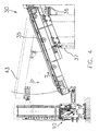
- device 10 is illustrated in the operating position, i.e. incorporated with a manufacturing machine in which there can be distinguished a feed device 30, represented in greater detail in Figure 4, which is capable of delivering the tread bands to a manufacturing drum (not shown), and a stepwise column 40 which assists the feeding of the tread bands to the aforesaid feed device 30, as described in greater detail further in the present description.
- a feed device 30 represented in greater detail in Figure 4
- stepwise column 40 which assists the feeding of the tread bands to the aforesaid feed device 30, as described in greater detail further in the present description.
- Device 10 comprises a loadbearing structure 11 provided with a supporting plane 12 located perpendicular to longitudinal axis 41 of stepwise column 40.
- Said supporting plane 12 performs the function of the supporting surface used by the operator during the transfer of a piece 50 of a tread band from one supporting plane of said "book trolley" (not shown) (arrow A in Figure 1) towards feed device 30 (arrow B in Figure 1).
- device 10 comprises a pair of first rollers 13, 14 which are attached to structure 11 and arranged perpendicularly to longitudinal axis 41, i.e. perpendicularly to the advancing direction of a piece 50 of tread band.
- Said first rollers 13, 14 are located close to exit edge 15 ( Figures 2 and 3) of supporting plane 14, in a position which is lower than said edge 15, and are caused to rotate about their corresponding longitudinal axes 13', 14' by a pneumatic motor 16 incorporated in loadbearing structure 11.
- Motor 16 drives a chain 17 ( Figure 1) which connects said motor to said first rollers 13, 14.
- chain 17 travels clockwise and induces rotation in the same direction in the aforesaid first rollers.
- device 10 comprises a second roller 18 of the idle type, unlike driven first rollers 13, 14, which is free to rotate about its longitudinal axis 18' located parallel to axes 13', 14' of first rollers 13, 14.
- Said second roller 18 is supported by a bracket 60 which is secured so as to rotate about a pivot 20 in such a way that second roller 18 adopts an intermediate position between the aforesaid first rollers 13, 14 during the operating step.
- bracket 60 comprises a first arm 19, at the free end of which is associated second roller 18, and a second arm 22, the free end of which is connected to an actuator 21 which is integral with loadbearing structure 11.
- actuator 21 is a cylinder of the pneumatic or hydraulic type.
- Bracket 60 comprising said first arm 19 and second arm 22, constitutes the member moving second roller 18, being secured so as to rotate about axis 23 of pivot 20 perpendicular to the plane of Figure 2 and parallel to longitudinal axes 13', 14', 18' cited above.
- Free end 24 of second arm 22 interacts with piston 25 of pneumatic cylinder 21, said end 24 and said piston 25 being pivoted so as rotate about an axis 26 parallel to axes 13', 14', 18', 23 mentioned above.
- pneumatic cylinder 21 operated by the operator as described further on in the present description, causes piston 25 to extend and at the same time displaces said cylinder 21 (arrow E in Figure 2) into position 29 which is represented by a dashed line in Figure 2.
- second roller 18 contacts, substantially through contact points, both the aforesaid first rollers 13, 14 at points 32, 33 respectively, said contact ensuring that second roller 18, which is not driven, is caused to rotate by said first rollers 13, 14.
- first rollers 13, 14 are made of metallic material (e.g., Fe 430 UNI 7070) and their outer surfaces are suitably treated so as to increase their hardness, rending them anti-adhesive with respect to the supporting fabric used, and to increase their roughness in order to ensure a greater hold on the supporting fabric itself.
- metallic material e.g., Fe 430 UNI 7070
- Said treatment may consist, for example, of a metal coating operation through which a thin coating, e.g. of 0.1 ⁇ m, based on vanadium, molybdenum, ceramic material or metal alloys in general, is applied to the outer surface of said first rollers.
- a thin coating e.g. of 0.1 ⁇ m, based on vanadium, molybdenum, ceramic material or metal alloys in general.
- second roller 18 is generally made of metallic material (e.g., Fe 430 UNI 7070) and is subsequently coated, with an expanded polyurethane material such as, for instance, the expanded cellular Vulkollan® produced by Bayer AG.
- metallic material e.g., Fe 430 UNI 7070
- expanded polyurethane material such as, for instance, the expanded cellular Vulkollan® produced by Bayer AG.
- said material is produced in densities between 350 and 650 kg/m 3 and can be compressed up to 80% of its original height with minimum permanent deformation.
- the aforesaid material has high impact elasticity, good resistance to abrasion, good resistance to aging, atmospheric agents and a wide range of solvents, and a hardness of between 65° Shore A and 70° Shore D.
- motor 16 which is responsible for moving said first rollers 13, 14 is a motor of the pneumatic type.
- said motor is such as to impart a peripheral speed of between 12 and 18 m/min to said first rollers, said motor rotating, for instance, at maximum of 500 rpm, having a maximum power of 22 Nm at 250 rpm and a peak torque of approximately 28 Nm.
- the drive torque provided by said motor is about 20 Nm, and the pulling force exerted on the supporting fabric, considering a roller having a radius of about 0.02 m, is about 1000 N.
- device 10 is shown in the situation in which supporting plane 12 is at the same level of the lower plane of a "book trolley" (not shown) from which the operator begins to take a piece 50 of a tread band in order to deliver it to feed device 30.
- piece 50 which is still provided with supporting fabric 51 mentioned above, is positioned so that supporting fabric 51 is in contact with the surface of the plane of said trolley.
- Said position is particularly advantageous in that supporting fabric 51 is already in the position which is required for the operator to slide piece 50 of tread band easily and with minimum effort from said plane of the "book trolley" towards supporting plane 12 of loadbearing structure 11 of device 10. The operator no longer has to turn over the tread band in order to remove the supporting fabric from it, as said operation is performed automatically by device 10 according to the invention, in ways which are illustrated later on in the present description.
- the operator draws piece 50 of tread band onto supporting plane 12 causing it to project beyond the end of said plane facing feed 30 while the remainder of said piece 50 is still supported on the plane of the "book trolley" from which it is taken. At this point the operator seizes an edge of supporting fabric 51 and manually detaches said fabric from piece 50 to which it is attached over a short length.
- the length of supporting fabric detached in this way is positioned by the operator so that it falls laterally onto loadbearing structure 11 of device 10, in corrispondence of the lateral surface of first rollers 13, 14, i.e. along edge 15 of supporting plane 12.
- an edge of said fabric, close to the corner of the first end of said tread band, is deliberately not attached thereto so that the operator can use said free edge as a grip when detaching the supporting fabric.
- the operator activates pneumatic cylinder 21 through a control panel and, in accordance with the method of operation described above, said cylinder 21 rotates the rotation axis of second roller 18, moving it from a first resting position to a second working position represented by the abovementioned intermediate position 31 between said first rollers 13, 14.
- second roller 18 intercepts length of fabric 51 which has been separated manually by the operator and causes said fabric to be positioned between the outer surfaces of first rollers 13, 14 and second roller 18, remaining fixed between said rollers.
- Second roller 18, although not driven, is caused to rotate by friction as a result of the contact with said first rollers and supporting fabric 51, placed between said rollers 13, 14, 18, is then separated from piece 50 of tread band in a direction perpendicular to the surface of attachment and drawn downwards.
- path 34 along which supporting fabric 51 is drawn is indicated by a dashed line and the pulling direction is indicated by arrow H.
- motor 16 stops automatically and the fabric removed is collected in a suitable container, preferably placed beneath said rollers, in that it is advantageously reusable.
- the transfer action is also assisted by activation of conveyor belt 35 with which feed device 30 is equipped, at the same time as motor 16 starts up, said conveyor belt 35 ( Figure 4) being driven by a motor 36 mounted on said feed device 30.
- motor 36 is associated with motor 16.
- piece 50 of tread band is directed towards the manufacturing drum (arrow I in Figure 4) driven by both the detachment operation performed by the combined rotation of rollers 13, 14, 18 of device 10 according to the invention and the action of conveyor belt 35 of feed device 30.
- device 10 When the operator has emptied one or more lower planes of the abovementioned "book trolley", device 10 is moved upwards (arrow C in Figure 1) to ease access to the higher planes in said trolley in such a way that, as mentioned above, supporting plane 12 of loadbearing structure 11 is at a height approximately equal to the height of the planes of the trolley from which the operator must take the tread bands which have yet to be delivered to feed device 30.
- supporting plane 12 has to move one step upwards along column 40 after every two or three planes in the book trolley have been emptied.
- structure 11 is capable of being moved along stepwise column 40 in a direction parallel to longitudinal axis 41 of the column in such a way that said structure 11 can be raised (arrow C) during the trolley discharge cycle so as to create a substantially continuous surface with the feed device, or lowered (arrow D) when a trolley which has been emptied is replaced with a subsequent trolley which is capable of being subjected to a new unloading cycle.
- Structure 11 is moved (arrows C and D) by a cylinder 37 ( Figure 4), of the pneumatic or hydraulic type, possessed by feed device 30, the latter being attached to the aforesaid structure 11 by means of a connecting member 38 which is integral with the structure itself.
- Said movement brings about a similar rise in connecting member 38 which draws structure 11 with it, raising device 10 by a predetermined step along stepwise column 40.
- said column 40 is provided with a plurality of engaging holes 39, with a predetermined spacing between them, so that the piston of cylinder 37 travels by an amount sufficient to move structure 11 of a predetermined amount every time a pulse is provided by the operator through a suitable control panel.
- Loadbearing structure 11 performs a movement equal to the predetermined step for each single pulse provided by the operator.
- the operator has a tip-up footboard available to him to assist unloading said tread bands, and in its operating position this enables him to reach even the highest planes on the abovementioned trolley conveniently.
- connecting member 38 is provided with a guide 42 which allows feed device 30 to make two movements: a first straight movement perpendicular to longitudinal axes 13', 14', 18' of said rollers (arrows L and M) and a second movement along guide 42 in a direction perpendicular to the plane of Figure 1.
- Said first movement takes place close to structure 11 (arrow L) as device 10 is moved upwards (arrow C) to allow the operator to gain access to the upper planes of the trolley (see position 43 in the dashed line in Figure 4), said approach being permitted to ensure correct movement of feed device 30.
- the first movement is performed away from structure 11 (arrow M) at the moment when device 10, having reached the end stop on stepwise column 40, has therefore to be returned to its starting condition to start a new unloading cycle on a subsequent trolley.
- the second movement, perpendicular to the plane of Figure 1, is performed to permit feed device 30 to deliver the tread bands to several feed lines leading to the manufacturing drum, said lines being generally possessed by the manufacturing machine.
- two separate feed lines consisting of two conveyor belts which deliver tread bands to said drum are generally provided upstream of said drum.
- Said type of plant provides for the manufacturing machine, equipped with said two feed lines, to move as a block perpendicularly to the plane of Figure 1, so that each of said lines is alternately opposite to feed device 30 in order to receive the tread bands loaded by the operator.
- feed device 30 is permitted to make the abovementioned second movement so that it can position itself opposite to a feed line and also it can load it during a step in which the manufacturing machine is moved into a second working position, e.g. to deposit the belt package onto the manufacturing drum.
- tread bands there is always a predetermined number of tread bands (generally three) on the feed lines of the manufacturing machine, and this enables the operator to concentrate for a longer time on other working steps other than the tread band preparation and loading steps.
- the device for automatic detachment of supporting fabric from a tread band according to the present invention has a plurality of advantages which cannot be achieved by the manual type of detachment of the known art.
- a first advantage consists in easing the work of the operator by considerably reducing the physical effort required for handling a substantially long piece of elastomeric material, in particular a tread band, and detaching a supporting fabric attached to it.
- a second advantage of the present invention consists in the fact that the abovementioned operating procedure ensures better quality for the piece of elastomeric material, and therefore for the tyre as a finished product incorporating said piece, since the latter is not subjected to stretching and vigorous handling by the operator, the supporting fabric attached to it being detached automatically.
- stretching and handling can give rise to higher or lower dimensional changes in said pieces causing a disadvantageous lack of uniformity in the finished product.
- a further advantage of the present invention consists in the fact that automation of the detaching step of the supporting fabric from the elastomeric piece makes it possible to speed up said operation (eliminating, as mentioned above, one or two handling operations on said tread band such as, for instance, the first and possibly also the second overturning of the tread band) and, therefore, increasing the productivity of the manufacturing plant.
- the operator will save time and energy which can be used in the other operations which he is called upon to perform.
- a further advantage consists in the fact that the detachment of the supporting fabric takes place optimally without running the risk that said fabric comes to pieces and portions of it can remain attached to the tread band. Said aspect is particularly undesirable in that said portions, trapped within the green tyre, give rise to the formation of discontinuities and air bubbles at the carcass/tread band interface during vulcanization of the tyre, starting tears which compromise the service life and a satisfactory performance of the finished product.
- the device according to the invention on the other hand makes it possible to reduce this risk to zero, given that the abovementioned rollers apply a constant and uniformly distributed pull over the entyre transverse cross section of the supporting fabric, a controlled action which cannot be guaranteed where the detachment operation is performed manually by the operator.
Abstract
Description
- The present invention relates to a method for automatically detaching the supporting fabric attached to a substantially elongated piece of elastomeric material, generally a length of tread band, prior to the transfer of said piece to a tyre manufacturing drum.
- Furthermore, the present invention relates to a device designed to automatically detach said supporting fabric from said substantially elongated piece of elastomeric material. Said device eases the task of the operator involved in the operation of detachment and, at the same time, makes it possible for said element to be moved towards a manufacturing drum mounted on the abovementioned machine.
- More particularly, the present invention relates to the automatic detachment of the supporting fabric attached to a length of tread band for tyres of the giant type, i.e. for tyres which are suitable to be used on heavy duty vehicles and the like.
- Prior art methods and apparatuses for automatically detaching the supporting fabric attached to a substantially elongated piece of elastomeric material are known from US-A-4 540 131 and EP-A-0 621 124.
- In the following of the present invention and in the pending claims, the term "elastomeric material" is intended to mean a rubber mixture in its entyrety, i.e. containing at least a basic polymer, the reinforcing fillers, as well as further product and process additives normally used for manufacturing and curing a pneumatic tyre.
- Tread bands for tyres of the giant type, as described further on in the course of the present description, are normally extruded continuously, because of their sizes and their weight considerably greater than the sizes and weight of the tread bands of car tyres. Thus said tread bands are cut up into pieces of predetermined length, stored in a store and taken therefrom for subsequent feeding to a tyre manufacturing machine.
- Said working procedure is substantially used also in the process of tyres manufacturing for cars where, however, it is generally preferred to store the tread band temporarily in the form of a continuous piece on a storage reel together with a supporting fabric which separates the overlapping turns of the elastomeric material from each other, the cutting to length operation of said tread band being performed subsequently, after separation of the supporting fabric, during the stage in which the tread band is delivered to said manufacturing drum.
- For greater simplicity of description, reference will be made in the following of the present description to processes for the manufacturing of pneumatic tyres which use lengths of tread band which have been precut to length during their manufacturing stage.
- Furthermore, whenever not expressly indicated otherwise, said lengths of tread band are to be understood to be either for tyres of the giant type or for car tyres, without distinction.
- In accordance with tyres manufacturing processes known in the art, the operation of removing the supporting fabric from a length of tread band is performed manually by an operator who is responsible, among other tasks, for preparing and positioning said tread band on a suitable feed device placed upstream from a manufacturing drum.
- More specifically, lengths of tread band are placed on the supporting planes of a distributor means, generally a moving trolley, positioned close to the aforesaid feed device, and the operator is required to handle each piece separately.
- Said pieces are carefully placed on said supporting planes in such a way that the supporting fabric is in contact with the surface of said planes.
- Therefore, the operator works on each piece, turning it over a first time so that the supporting fabric is uppermost, and then detaching said fabric in a completely manual way, using only his own strength.
- Once the supporting fabric has been removed from the surface of the piece, the successive operations performed by the operator depend on the nature of the process and the manufacturing machine used.
- In the case where the abovementioned feed device delivers the tread band in a position above the manufacturing drum, the piece of tread band must be turned over a second time to ensure that it is correctly positioned on the cylindrical surface of the drum.
- Once said second overturning movement has been performed, the operator has to manually push the tread band up onto said feed device, which is upstream from the manufacturing drum, and which is provided with motor-driven rollers or with a conveyor belt which deliver said tread band to the manufacturing drum.
- When, however, said feed device delivers the tread band to a position below the manufacturing drum, the operator does not have to turn said piece over a second time once the supporting fabric has been removed, and merely has to push it towards said feed device.
- According to Applicant's perception, manual performance of the abovementioned operations of turning the tread band over and detaching the supporting fabric attached to the latter is particularly onerous for the operator, because of the appreciable weight of the piece, and he is required to make a more than negligible repeated physical effort which is quite harmful to the integrity of the piece that undergoes a plurality of stretching movements and dimensional changes because of the plasticity of the nonvulcanized material, which compromise the quality of the finished product.
- In fact, it should be emphasized that in the case of tyres of the giant type, each piece of tread band has a weight which generally varies between 25 and 30 kg.
- Furthermore, said physical effort is not only required for turning the piece of tread band over and for detaching the supporting fabric, which must be performed at the same time over the full width of the piece, and progressively in a longitudinal direction along it, but also for conveying said piece, pushed by the operator's force, towards the feed device of the manufacturing drum.
- The process of producing a tyre, in particular a tyre of the giant type, makes use of manufacturing machines which, operating according to a predetermined sequence of stages performed partly in a wholly automatic way and partly semiautomatically on two or more manufacturing drums, make it possible to assemble the plurality of semifinished components which make up a finished tyre.
- Said semifinished components are represented by: the liner, i.e. a layer which is impermeable to air and which coats the inside of the carcass of a tubeless tyre, the carcass ply, the chafers, the fillers beneath the belt ply, the belt plies (in general three separate strips of belt ply overlapped by a further strip with circumferential cords), the tread band and the sides walls.
- The structure and the operation of an manufacturing machine as a whole are not described in the following since they are not relevant to said invention, and any manufacturing machine of the known art may therefore be taken into consideration.
- As mentioned above, the tread band represents one of the semifinished products used in the manufacturing process of a tyre, and is produced by an extrusion operation by using a mixture of predetermined formulation which results in the production of a continuous piece of elastomeric material.
- Through the use of dies of predetermined cross section, said continuous piece is shaped into a profile which is substantially trapezoidal in transverse cross section.
- Thus, the obtained continuous piece of the tread band is subjected to a cooling stage which is conventionally performed by immersing it into a cooling liquid, e.g. water at ambient temperature.
- Once said cooling stage is complete, the lower surface of said piece of tread band, that is the surface which constitutes the larger base of the abovementioned trapezoidal cross section and which comes into contact with the abovementioned belt package during manufacturing, is attached to a supporting fabric.
- Said fabric performs the function of preserving the adhesiveness of the mixture on the lower surface of the tread band, that is the surface which will come into direct contact with the underlying belt package during the tyre manufacturing process.
- In fact it should be emphasized that for reasons relating to the process and the stocks in store, generally the tread band, once it has been produced, is not immediately used but remains stored in the stores for a variable period of time of between few hours and few days.
- During said period of time the tread band is inevitably in contact with dust and/or dirt present in the surrounding environment; there is therefore a need to protect its surfaces, in particular to preserve its adhesiveness, by coating it with a supporting fabric.
- More particularly, in the case of tread bands for vehicle tyres, a continuous piece of tread band approximately 100 metres long is wound onto a reel together with a suitable fabric, e.g. Meraklon®.
- On the other hand, in the case of tread bands for giant tyres the tread band is coated with a supporting fabric which generally consists of a sheet of polyethylene.
- The tread band attached to the supporting fabric is then subjected to a cutting to length operation so as to produce pieces of tread band which have predetermined dimensional features for use during the manufacturing stage, said features being suitable for the manufacturing of a particular tyre.
- As mentioned above, the cut pieces of the tread band are placed on the supporting planes of a carrying trolley, known in the technical language as "book trolley", which has the special feature of having the supporting planes all hinged so as to rotate along the same side, i.e. the longer side of said planes, the latter adopting an arrangement similar to that of the pages of a book.
- Once it has been loaded, said trolley is brought up close to the manufacturing machine, upstream of a manufacturing drum, where the operator, as indicated above, manually detaches the supporting fabric from the tread band and delivers it to a roller or belt feed device which feeds said manufacturing drum.
- The Applicant has found that the abovementioned operations, which are traditionally performed manually by the operator with a considerable expenditure of physical effort, with a particularly high risk of accidents and with qualitative deterioration of the tyre being processed, can be performed simply, correctly and with minimum physical effort by providing the manufacturing machine with a device capable of automatically detaching the supporting fabric from the tread band and advancing said tread band towards the feed device present on said machine, upstream of the manufacturing drum.
- Furthermore, the Applicant has found that said device, in addition to reducing the operator's tyredness, provides a greater saving in time in performing the abovementioned operations in comparison with the manual type procedure of the known art, to the full advantage of the productivity of the plant.
- Furthermore, the Applicant has found that said device guarantees a better quality of the finished product, in that it makes it possible to avoid unnecessary and disadvantageous stress of the green elastomeric material, and to reduce the risk that portions of the supporting fabric might remain attached to the piece of tread band and, therefore, be found within the green tyre at the end of the manufacturing procedure.
- According to a first aspect thereof, the present invention relates to a method for detaching a supporting fabric from a substantially long piece of elastomeric material as defined in claim 1.
- Preferably the supporting fabric is detached simultaneously over the entyre width of said elastomeric piece, progressively in a direction longitudinal to the latter. Preferably said detachment action is performed by a traction in a direction perpendicular to the surface of attachment with said elastomeric piece, thus causing it to move towards the feed device.
- According to a second aspect thereof, the present invention relates to a device for the automatic detachment of a supporting fabric from a substantially long piece of elastomeric material as defined in claim 7.
- Further features and advantages of the present invention will be more clearly apparent in the light of the description of a preferred embodiment thereof with reference to the appended drawings, which are provided purely by way of explanation and without any limitative intent, in which:
- Figure 1
- shows a side view, in partial cross section, of a device for automatically detaching the supporting fabric according to the present invention, incorporated in a machine for the manufacturing of tyres;
- Figure 2
- shows a side view, in partial cross section, of a detail of the device in Figure 1;
- Figure 3
- shows a front view, in partial cross section, of a detail of the device in Figure 1; and
- Figure 4
- shows a side view of the device in Figure 1 incorporated with a feed device attached to the device itself.
- Figure 1 illustrates an embodiment of a
device 10 for automatically detaching a supporting fabric 51 attached to apiece 50 of a tread band according to the present invention. - In Figure 1,
device 10 is illustrated in the operating position, i.e. incorporated with a manufacturing machine in which there can be distinguished afeed device 30, represented in greater detail in Figure 4, which is capable of delivering the tread bands to a manufacturing drum (not shown), and astepwise column 40 which assists the feeding of the tread bands to theaforesaid feed device 30, as described in greater detail further in the present description. -
Device 10 according to the invention comprises aloadbearing structure 11 provided with a supportingplane 12 located perpendicular tolongitudinal axis 41 ofstepwise column 40. - Said supporting
plane 12 performs the function of the supporting surface used by the operator during the transfer of apiece 50 of a tread band from one supporting plane of said "book trolley" (not shown) (arrow A in Figure 1) towards feed device 30 (arrow B in Figure 1). - Furthermore,
device 10 according to the present invention comprises a pair offirst rollers structure 11 and arranged perpendicularly tolongitudinal axis 41, i.e. perpendicularly to the advancing direction of apiece 50 of tread band. - Said
first rollers plane 14, in a position which is lower than saidedge 15, and are caused to rotate about their corresponding longitudinal axes 13', 14' by a pneumatic motor 16 incorporated inloadbearing structure 11. - Motor 16 drives a chain 17 (Figure 1) which connects said motor to said
first rollers - In figure 1 chain 17 travels clockwise and induces rotation in the same direction in the aforesaid first rollers.
- Furthermore,
device 10 according to the present invention comprises asecond roller 18 of the idle type, unlike drivenfirst rollers first rollers - Said
second roller 18 is supported by abracket 60 which is secured so as to rotate about apivot 20 in such a way thatsecond roller 18 adopts an intermediate position between the aforesaidfirst rollers - In greater detail,
bracket 60 comprises afirst arm 19, at the free end of which is associatedsecond roller 18, and asecond arm 22, the free end of which is connected to anactuator 21 which is integral withloadbearing structure 11. - In a preferred embodiment of the present invention,
actuator 21 is a cylinder of the pneumatic or hydraulic type. -
Bracket 60, comprising saidfirst arm 19 andsecond arm 22, constitutes the member movingsecond roller 18, being secured so as to rotate about axis 23 ofpivot 20 perpendicular to the plane of Figure 2 and parallel to longitudinal axes 13', 14', 18' cited above. -
Free end 24 ofsecond arm 22 interacts withpiston 25 ofpneumatic cylinder 21, saidend 24 and saidpiston 25 being pivoted so as rotate about anaxis 26 parallel to axes 13', 14', 18', 23 mentioned above. - In the embodiment shown in the figures, the set of elements which permits the movement of
second roller 18, said set comprisingpneumatic cylinder 21,pivot 20 andbracket 60, is present at both one end 27 (Figure 3) ofsecond roller 18 and at a second end 28 (Figure 3) of saidsecond roller 18. - In a further embodiment (not shown), instead of providing a double set of movement members on each of the ends of
second roller 18, there is a single set which is located, for example, in an intermediate position along the longitudinal length of said second roller. - Movement of
second roller 18 into said intermediate position betweenfirst rollers - The action of
pneumatic cylinder 21, operated by the operator as described further on in the present description, causespiston 25 to extend and at the same time displaces said cylinder 21 (arrow E in Figure 2) intoposition 29 which is represented by a dashed line in Figure 2. - Since
piston 25 is attached tosecond arm 22 ofbracket 60 at a point alongaxis 26, the displacement suffered by pneumatic cylinder 21 (arrow E) causes anticlockwise rotation (arrow F) ofbracket 60. Said rotation (arrow F) produces corresponding anticlockwise rotation (arrow G) ofsecond roller 18 which thus adopts saidintermediate position 31 betweenfirst rollers - In said
intermediate position 31,second roller 18 contacts, substantially through contact points, both the aforesaidfirst rollers points second roller 18, which is not driven, is caused to rotate by saidfirst rollers - With reference to Figures 1 and 2, where, as mentioned above, chain 17 of motor 16 moves clockwise,
second roller 18 is caused to move anticlockwise. - In general
first rollers - Said treatment may consist, for example, of a metal coating operation through which a thin coating, e.g. of 0.1 µm, based on vanadium, molybdenum, ceramic material or metal alloys in general, is applied to the outer surface of said first rollers.
- Similarly,
second roller 18 is generally made of metallic material (e.g., Fe 430 UNI 7070) and is subsequently coated, with an expanded polyurethane material such as, for instance, the expanded cellular Vulkollan® produced by Bayer AG. - Unlike conventional expanded polyurethane materials, said material is produced in densities between 350 and 650 kg/m3 and can be compressed up to 80% of its original height with minimum permanent deformation.
- Furthermore, the aforesaid material has high impact elasticity, good resistance to abrasion, good resistance to aging, atmospheric agents and a wide range of solvents, and a hardness of between 65° Shore A and 70° Shore D.
- As stated above, motor 16 which is responsible for moving said
first rollers - In general, said motor is such as to impart a peripheral speed of between 12 and 18 m/min to said first rollers, said motor rotating, for instance, at maximum of 500 rpm, having a maximum power of 22 Nm at 250 rpm and a peak torque of approximately 28 Nm.
- The drive torque provided by said motor is about 20 Nm, and the pulling force exerted on the supporting fabric, considering a roller having a radius of about 0.02 m, is about 1000 N.
- Therefore, the operation of
device 10 according to the present invention is as follows. - In Figure 1,
device 10 is shown in the situation in which supportingplane 12 is at the same level of the lower plane of a "book trolley" (not shown) from which the operator begins to take apiece 50 of a tread band in order to deliver it to feeddevice 30. - During said step,
piece 50, which is still provided with supporting fabric 51 mentioned above, is positioned so that supporting fabric 51 is in contact with the surface of the plane of said trolley. - Said position is particularly advantageous in that supporting fabric 51 is already in the position which is required for the operator to slide
piece 50 of tread band easily and with minimum effort from said plane of the "book trolley" towards supportingplane 12 ofloadbearing structure 11 ofdevice 10. The operator no longer has to turn over the tread band in order to remove the supporting fabric from it, as said operation is performed automatically bydevice 10 according to the invention, in ways which are illustrated later on in the present description. - More specifically, the operator draws
piece 50 of tread band onto supportingplane 12 causing it to project beyond the end of saidplane facing feed 30 while the remainder of saidpiece 50 is still supported on the plane of the "book trolley" from which it is taken. At this point the operator seizes an edge of supporting fabric 51 and manually detaches said fabric frompiece 50 to which it is attached over a short length. - The length of supporting fabric detached in this way is positioned by the operator so that it falls laterally onto
loadbearing structure 11 ofdevice 10, in corrispondence of the lateral surface offirst rollers edge 15 of supportingplane 12. - In order to further ease the task of the operator, during the step of attaching the supporting fabric to each tread band, an edge of said fabric, close to the corner of the first end of said tread band, is deliberately not attached thereto so that the operator can use said free edge as a grip when detaching the supporting fabric.
- Once the length of fabric 51 has been positioned laterally on the surface of said first rollers, the operator activates
pneumatic cylinder 21 through a control panel and, in accordance with the method of operation described above, saidcylinder 21 rotates the rotation axis ofsecond roller 18, moving it from a first resting position to a second working position represented by the abovementionedintermediate position 31 between saidfirst rollers - Following said rotation (arrow G),
second roller 18 intercepts length of fabric 51 which has been separated manually by the operator and causes said fabric to be positioned between the outer surfaces offirst rollers second roller 18, remaining fixed between said rollers. - At this step, once
second roller 18 has been positioned, motor 16 mentioned above comes into operation and causes saidfirst rollers -
Second roller 18, although not driven, is caused to rotate by friction as a result of the contact with said first rollers and supporting fabric 51, placed between saidrollers piece 50 of tread band in a direction perpendicular to the surface of attachment and drawn downwards. - In Figure 2,
path 34 along which supporting fabric 51 is drawn is indicated by a dashed line and the pulling direction is indicated by arrow H. - Once supporting fabric 51 has been detached from the tread band, motor 16 stops automatically and the fabric removed is collected in a suitable container, preferably placed beneath said rollers, in that it is advantageously reusable.
- The pulling force exerted on supporting fabric 51 by
rollers device 10 according to the invention, in addition to detaching said fabric from the tread band, pulls the tread band along supportingplane 12, pushing it towardsfeed device 30, thus allowing the transfer of said tread band from the plane of the "book trolley" (arrow A) onto the abovementioned feed device (arrow B) so that it can be delivered to a manufacturing drum located downstream from said device. - The transfer action is also assisted by activation of
conveyor belt 35 with which feeddevice 30 is equipped, at the same time as motor 16 starts up, said conveyor belt 35 (Figure 4) being driven by amotor 36 mounted on saidfeed device 30. Preferablymotor 36 is associated with motor 16. - Therefore, in this
way piece 50 of tread band is directed towards the manufacturing drum (arrow I in Figure 4) driven by both the detachment operation performed by the combined rotation ofrollers device 10 according to the invention and the action ofconveyor belt 35 offeed device 30. - When the operator has emptied one or more lower planes of the abovementioned "book trolley",
device 10 is moved upwards (arrow C in Figure 1) to ease access to the higher planes in said trolley in such a way that, as mentioned above, supportingplane 12 ofloadbearing structure 11 is at a height approximately equal to the height of the planes of the trolley from which the operator must take the tread bands which have yet to be delivered to feeddevice 30. - Generally, supporting
plane 12 has to move one step upwards alongcolumn 40 after every two or three planes in the book trolley have been emptied. - More particularly,
structure 11 is capable of being moved alongstepwise column 40 in a direction parallel tolongitudinal axis 41 of the column in such a way that saidstructure 11 can be raised (arrow C) during the trolley discharge cycle so as to create a substantially continuous surface with the feed device, or lowered (arrow D) when a trolley which has been emptied is replaced with a subsequent trolley which is capable of being subjected to a new unloading cycle. -
Structure 11 is moved (arrows C and D) by a cylinder 37 (Figure 4), of the pneumatic or hydraulic type, possessed byfeed device 30, the latter being attached to theaforesaid structure 11 by means of a connectingmember 38 which is integral with the structure itself. - In other words, when the operator wishes to raise
device 10 in order to unload a higher plane of said trolley, he operatescylinder 37 which controls upward movement offeed device 30. - Said movement brings about a similar rise in connecting
member 38 which drawsstructure 11 with it, raisingdevice 10 by a predetermined step alongstepwise column 40. - In fact, said
column 40 is provided with a plurality of engagingholes 39, with a predetermined spacing between them, so that the piston ofcylinder 37 travels by an amount sufficient to movestructure 11 of a predetermined amount every time a pulse is provided by the operator through a suitable control panel. -
Loadbearing structure 11 performs a movement equal to the predetermined step for each single pulse provided by the operator. - Therefore, the combination of the movements mentioned above makes it possible for the operator to gain access easily to all the planes of the "book trolley" and to unload the tread bands contained from the planes of the trolley easily and conveniently.
- Furthermore, the operator has a tip-up footboard available to him to assist unloading said tread bands, and in its operating position this enables him to reach even the highest planes on the abovementioned trolley conveniently.
- In accordance with the embodiment illustrated in the figures, connecting
member 38 is provided with aguide 42 which allowsfeed device 30 to make two movements: a first straight movement perpendicular to longitudinal axes 13', 14', 18' of said rollers (arrows L and M) and a second movement alongguide 42 in a direction perpendicular to the plane of Figure 1. - Said first movement takes place close to structure 11 (arrow L) as
device 10 is moved upwards (arrow C) to allow the operator to gain access to the upper planes of the trolley (seeposition 43 in the dashed line in Figure 4), said approach being permitted to ensure correct movement offeed device 30. - The first movement is performed away from structure 11 (arrow M) at the moment when
device 10, having reached the end stop onstepwise column 40, has therefore to be returned to its starting condition to start a new unloading cycle on a subsequent trolley. - The second movement, perpendicular to the plane of Figure 1, is performed to permit
feed device 30 to deliver the tread bands to several feed lines leading to the manufacturing drum, said lines being generally possessed by the manufacturing machine. - In fact, in order to increase the productivity of a tyre manufacturing process, two separate feed lines consisting of two conveyor belts which deliver tread bands to said drum are generally provided upstream of said drum.
- Said type of plant provides for the manufacturing machine, equipped with said two feed lines, to move as a block perpendicularly to the plane of Figure 1, so that each of said lines is alternately opposite to feed
device 30 in order to receive the tread bands loaded by the operator. - In order to reduce process dead times and to increase the number of tread bands loaded onto said feed lines, while at the same time ensuring greater independence of movement for the operator who is responsible for a plurality of operations on the machine, in addition to loading the tread bands,
feed device 30 is permitted to make the abovementioned second movement so that it can position itself opposite to a feed line and also it can load it during a step in which the manufacturing machine is moved into a second working position, e.g. to deposit the belt package onto the manufacturing drum. - In this way it is guaranteed that there is always a predetermined number of tread bands (generally three) on the feed lines of the manufacturing machine, and this enables the operator to concentrate for a longer time on other working steps other than the tread band preparation and loading steps.
- Therefore, the device for automatic detachment of supporting fabric from a tread band according to the present invention has a plurality of advantages which cannot be achieved by the manual type of detachment of the known art.
- As cited above, a first advantage consists in easing the work of the operator by considerably reducing the physical effort required for handling a substantially long piece of elastomeric material, in particular a tread band, and detaching a supporting fabric attached to it.
- A second advantage of the present invention consists in the fact that the abovementioned operating procedure ensures better quality for the piece of elastomeric material, and therefore for the tyre as a finished product incorporating said piece, since the latter is not subjected to stretching and vigorous handling by the operator, the supporting fabric attached to it being detached automatically. As cited above, because of the high plasticity of the green material, such stretching and handling can give rise to higher or lower dimensional changes in said pieces causing a disadvantageous lack of uniformity in the finished product.
- A further advantage of the present invention consists in the fact that automation of the detaching step of the supporting fabric from the elastomeric piece makes it possible to speed up said operation (eliminating, as mentioned above, one or two handling operations on said tread band such as, for instance, the first and possibly also the second overturning of the tread band) and, therefore, increasing the productivity of the manufacturing plant. In fact, in comparison with the traditional manual technique, the operator will save time and energy which can be used in the other operations which he is called upon to perform.
- A further advantage consists in the fact that the detachment of the supporting fabric takes place optimally without running the risk that said fabric comes to pieces and portions of it can remain attached to the tread band. Said aspect is particularly undesirable in that said portions, trapped within the green tyre, give rise to the formation of discontinuities and air bubbles at the carcass/tread band interface during vulcanization of the tyre, starting tears which compromise the service life and a satisfactory performance of the finished product. The device according to the invention on the other hand makes it possible to reduce this risk to zero, given that the abovementioned rollers apply a constant and uniformly distributed pull over the entyre transverse cross section of the supporting fabric, a controlled action which cannot be guaranteed where the detachment operation is performed manually by the operator.
Claims (15)
- Method for detaching a supporting fabric (51) from a substantially elongated piece (50) of elastomeric material, prior to the transfer of said piece (50) to a tyre manufacturing drum, comprising the steps of:- transferring said piece from a distributor means towards a feed device (30) located upstream of said manufacturing drum;- adjusting the height of a supporting plane (12), on which the elongated piece (50) is supported during the transferring step, so that the transfer of said elongated piece (50) from said distributor means to said feed device (30) is effected along a surface which is substantially continuous and horizontal, and- detaching said supporting fabric (51) from said elongated piece (50) while moving said elongated piece (50) towards said feed device (30) by intercepting said supporting fabric between at least a pair of first rollers (13, 14) and at least one second roller (18) and by driving in rotation said at least a pair of first rollers.
- Method according to Claim 1, characterized in that the supporting plane (12) interacts with the feed device (30) before the transferring step is performed.
- Method according to Claim 1, characterized in that said supporting fabric (51) is detached from said elongated piece (50) over its entire width at the same time and progressively in a direction longitudinal to said elongated piece (50).
- Method according to Claim 1, characterized in that said supporting fabric (51) is detached by pulling said supporting fabric (51) in a direction perpendicular to the surface of attachment with said elongated piece (50) .
- Method according to Claim 1, characterized in that said action of detaching the supporting fabric (51) causes the elongated piece (50) to move towards said feed device (30).
- Method according to Claim 1, characterized in that said detachment and said movement of said elongated piece (50) are manually initiated by initially detaching an end of said fabric (51) and inserting said end into a pulling device (10).
- Device (10) for the automatic detachment of a supporting fabric (51) from a substantially elongated piece (50) of elastomeric material, comprising:- at least a supporting plane (12) for supporting said substantially elongated piece (50);- means (37; 38; 11; 40) for moving the supporting plane (12) in a direction perpendicular to the advancing direction (A, B) of the elongated piece (50);- at least a pair of first rollers (13, 14) which are located close to an exit edge (15) of said supporting plane (12) at a position lower than said exit edge (15);- at least a second roller (18) which can be moved alternately in two directions between a first resting position in which said second roller (18) is at a distance from said pair of first rollers (13, 14), and a second working position in which said second roller is positioned between said at least a pair of first rollers and intercepts said supporting fabric (51) in order to detach said supporting fabric (51) from said substantially elongated piece (50), and- at least one actuator (21) capable of performing said movements of said second roller (18),
wherein the rotation axes (13', 14') of said at least a pair of first rollers (13, 14) and said at least a second roller (18) are parallel to each other and perpendicular to the advancing direction (A, B) of said elongated piece (50). - Device (10) according to Claim 7, characterized in that said at least a pair of first rollers (13, 14) is driven in rotation by a motor means (16).
- Device (10) according to Claim 7, characterized in that said at least a second roller (18) is idle.
- Device (10) according to Claim 7, characterized in that said at least a second roller (18) is caused to rotate on contact with said at least a pair of first rollers (13, 14).
- Device (10) according to Claim 7, characterized in that said at least one actuator (21) has one end attached to an end (24) of a bracket (60) having on the opposite end the rotation axis (18') of said at least a second roller (18), said bracket (60) being pivoted at a fixed point with respect to the rotation axis (13', 14') of said at least a pair of first rollers (13, 14), and in that the rotation (E, F) of said bracket (60) around said pivot (20) moves said at least a second roller (18) between said two working and resting positions respectively.
- Device (10) according to Claim 7, characterized in that it comprises a loadbearing structure (11) equipped with said at least a supporting plane (12).
- Device (10) according to Claim 12, characterized in that said at least a pair of first rollers (13, 14) and said at least a second roller (18) are supported by said loadbearing structure (11).
- Device (10) according to Claim 12, characterized in that it is connected to a feed device (30) by means of a connecting member (38) integral with said loadbearing structure (11).
- Device (10) according to Claim 14, characterized in that the feed device (30) comprises a cylinder (37) of the pneumatic or hydraulic type for moving the loadbearing structure (11) along a stepwise column (40).
Priority Applications (1)
| Application Number | Priority Date | Filing Date | Title |
|---|---|---|---|
| EP00981348A EP1254018B1 (en) | 1999-12-21 | 2000-12-07 | Method and apparatus for automatically detaching the supporting fabric from an elastomeric band |
Applications Claiming Priority (6)
| Application Number | Priority Date | Filing Date | Title |
|---|---|---|---|
| EP99125487 | 1999-12-21 | ||
| EP99125487 | 1999-12-21 | ||
| US17328999P | 1999-12-28 | 1999-12-28 | |
| US173289P | 1999-12-28 | ||
| EP00981348A EP1254018B1 (en) | 1999-12-21 | 2000-12-07 | Method and apparatus for automatically detaching the supporting fabric from an elastomeric band |
| PCT/EP2000/012359 WO2001045923A1 (en) | 1999-12-21 | 2000-12-07 | Method and apparatus for automatically detaching the supporting fabric from an elastomeric band |
Publications (2)
| Publication Number | Publication Date |
|---|---|
| EP1254018A1 EP1254018A1 (en) | 2002-11-06 |
| EP1254018B1 true EP1254018B1 (en) | 2006-03-08 |
Family
ID=26153206
Family Applications (1)
| Application Number | Title | Priority Date | Filing Date |
|---|---|---|---|
| EP00981348A Expired - Lifetime EP1254018B1 (en) | 1999-12-21 | 2000-12-07 | Method and apparatus for automatically detaching the supporting fabric from an elastomeric band |
Country Status (7)
| Country | Link |
|---|---|
| US (2) | US7081181B2 (en) |
| EP (1) | EP1254018B1 (en) |
| AT (1) | ATE319557T1 (en) |
| AU (1) | AU1862201A (en) |
| DE (1) | DE60026573T2 (en) |
| ES (1) | ES2260075T3 (en) |
| WO (1) | WO2001045923A1 (en) |
Families Citing this family (3)
| Publication number | Priority date | Publication date | Assignee | Title |
|---|---|---|---|---|
| CN102781654B (en) | 2010-02-22 | 2016-10-26 | 倍耐力轮胎股份公司 | It is provided with the elongated elements of two service fabric with the method and apparatus building wheel tyre for unwinding |
| ITMI20131281A1 (en) * | 2013-07-31 | 2015-02-01 | Pirelli | METHOD AND APPARATUS FOR FEEDING A PLURALITY OF TREAD BANDS IN A PROCESS FOR PACKAGING TIRES FOR VEHICLE WHEELS |
| DE102014015490A1 (en) * | 2014-10-14 | 2016-04-14 | Harburg-Freudenberger Maschinenbau Gmbh | Apparatus and process for the production of green tires |
Family Cites Families (22)
| Publication number | Priority date | Publication date | Assignee | Title |
|---|---|---|---|---|
| US3407106A (en) * | 1964-08-24 | 1968-10-22 | Bacon American Corp | Apparatus for retreading tires |
| US3546042A (en) | 1966-10-14 | 1970-12-08 | Doris Heck | Device for feeding blank tread strips to vehicle tires |
| US3731614A (en) * | 1971-12-17 | 1973-05-08 | D Smith | Apparatus for cooking food products |
| JPS59108652A (en) | 1982-12-14 | 1984-06-23 | Bridgestone Corp | Equipment for unwinding and conveying sheet wound as roll |
| US4580738A (en) | 1983-12-05 | 1986-04-08 | The Goodyear Tire & Rubber Company | Controlled tension unwinding system |
| US4951892A (en) | 1988-12-30 | 1990-08-28 | Bridgestone/Firestone, Inc. | Server system for rubberized sheets |
| US5108534A (en) * | 1990-10-03 | 1992-04-28 | Eastman Kodak Company | Apparatus and method for peeling a sheet or layer from a workpiece |
| DE4107669C1 (en) * | 1991-03-09 | 1992-07-02 | Seidl-Lichthardt, Johanna, 8000 Muenchen, De | |
| US5370754A (en) * | 1991-06-27 | 1994-12-06 | Pfizer Inc. | Automatic motorless label applying system |
| US5141584A (en) * | 1991-11-27 | 1992-08-25 | Polaroid Corporation | Apparatus and method for controlling the delamination of a laminate |
| US5169474A (en) * | 1991-11-27 | 1992-12-08 | Polaroid Corporation | Apparatus and method for delaminating a composite laminate structure |
| US5399228A (en) * | 1992-02-21 | 1995-03-21 | Best Label Co., Inc. | Apparatus and method for automatically applying adhesive-backed labels to moving articles |
| IT1259732B (en) * | 1992-07-07 | 1996-03-26 | Gisulfo Baccini | COLLECTION DEVICE, OVERLAPPING AND LOCKING OF SHEETS FOR GREEN-TAPE CIRCUITS |
| JP3132214B2 (en) * | 1993-01-14 | 2001-02-05 | 株式会社村田製作所 | Manufacturing method of ceramic multilayer circuit component and ceramic green sheet handling device |
| CA2104617A1 (en) * | 1993-04-21 | 1994-10-22 | John Patrick Roman | Method and apparatus for building a tire and storing strip material |
| US5520776A (en) * | 1994-05-10 | 1996-05-28 | Polaroid Corporation | Method and apparatus for delaminating a laminate |
| US5478428A (en) * | 1994-08-01 | 1995-12-26 | Grand Rapids Label Company | Label separator and method for separating a label from a backing |
| US5643392A (en) * | 1994-12-19 | 1997-07-01 | Polaroid Corporation | Method of and apparatus for delaminating imaging media |
| US6349756B1 (en) * | 1998-10-23 | 2002-02-26 | Zih Corporation | Peel assembly for a printer |
| IT1315144B1 (en) * | 2000-11-09 | 2003-02-03 | Gisulfo Baccini | AUTOMATIC SEPARATOR AND PROCEDURE FOR OBTAINING PERMICROELECTRONIC CIRCUITS. |
| US6627027B2 (en) * | 2001-08-13 | 2003-09-30 | Ben Huang | Method of making a shock absorbing grip for golf clubs and the like |
| JP3990264B2 (en) * | 2002-12-10 | 2007-10-10 | 富士フイルム株式会社 | Protective sheet peeling device |
-
2000
- 2000-12-07 AT AT00981348T patent/ATE319557T1/en not_active IP Right Cessation
- 2000-12-07 DE DE60026573T patent/DE60026573T2/en not_active Expired - Lifetime
- 2000-12-07 EP EP00981348A patent/EP1254018B1/en not_active Expired - Lifetime
- 2000-12-07 WO PCT/EP2000/012359 patent/WO2001045923A1/en active Search and Examination
- 2000-12-07 US US10/168,064 patent/US7081181B2/en not_active Expired - Lifetime
- 2000-12-07 ES ES00981348T patent/ES2260075T3/en not_active Expired - Lifetime
- 2000-12-07 AU AU18622/01A patent/AU1862201A/en not_active Abandoned
-
2006
- 2006-06-08 US US11/448,818 patent/US7416012B2/en not_active Expired - Lifetime
Also Published As
| Publication number | Publication date |
|---|---|
| US7081181B2 (en) | 2006-07-25 |
| DE60026573T2 (en) | 2006-12-14 |
| AU1862201A (en) | 2001-07-03 |
| EP1254018A1 (en) | 2002-11-06 |
| ATE319557T1 (en) | 2006-03-15 |
| ES2260075T3 (en) | 2006-11-01 |
| US20060283556A1 (en) | 2006-12-21 |
| DE60026573D1 (en) | 2006-05-04 |
| US7416012B2 (en) | 2008-08-26 |
| US20030131920A1 (en) | 2003-07-17 |
| WO2001045923A1 (en) | 2001-06-28 |
Similar Documents
| Publication | Publication Date | Title |
|---|---|---|
| US10919243B2 (en) | Method and apparatus for feeding a plurality of tread bands in a process for building tyres for vehicle wheels | |
| EP3212390B1 (en) | Process and apparatus for automatically applying a noise reducing element to a tyre for vehicle wheels | |
| US3223573A (en) | Apparatus for applying unvulcanized rubber material to a tire body | |
| JPH0260480B2 (en) | ||
| JPH028893B2 (en) | ||
| US20160263848A1 (en) | Process and apparatus for manufacturing tyres for vehicle wheels | |
| US7416012B2 (en) | Apparatus for detaching supporting fabric from elastomeric material | |
| CN100548651C (en) | The feedway of green tire belt reinforcement strip material | |
| MX2013013680A (en) | Process and apparatus for building tyres for vehicle wheels. | |
| US4983243A (en) | Method of and apparatus for automatically winding adhesive ribbon-like material | |
| CN111392510B (en) | Automatic assembling and disassembling method for wire spool of tire steel wire winding device | |
| JP6262647B2 (en) | Method and plant for building tires for vehicle wheels | |
| JPS6211635A (en) | Method and device for winding and forming of unvulcanized tire member | |
| US20050183815A1 (en) | Tire ply forming apparatus and process | |
| KR100441958B1 (en) | Building Assemble Apparatus of Green Tire for Off The Road Vehicles | |
| JP2000263657A (en) | Method and apparatus for winding sheet body | |
| KR100187625B1 (en) | A shipment device and a shipment method for a green tyre | |
| WO2008088307A2 (en) | Device and method for manufacturing tire having improved bead portion | |
| JPS646944B2 (en) | ||
| JPS6014698B2 (en) | Apparatus and method for hemming reinforced elastomeric structures | |
| JPH11129346A (en) | Method for supplying member in tire molding machine and member supplying device | |
| JPH0137262B2 (en) | ||
| JPH10235746A (en) | Method and device for molding small-size bias tire |
Legal Events
| Date | Code | Title | Description |
|---|---|---|---|
| PUAI | Public reference made under article 153(3) epc to a published international application that has entered the european phase |
Free format text: ORIGINAL CODE: 0009012 |
|
| 17P | Request for examination filed |
Effective date: 20020624 |
|
| AK | Designated contracting states |
Kind code of ref document: A1 Designated state(s): AT BE CH CY DE DK ES FI FR GB GR IE IT LI LU MC NL PT SE TR |
|
| AX | Request for extension of the european patent |
Free format text: AL;LT;LV;MK;RO;SI |
|
| 17Q | First examination report despatched |
Effective date: 20040223 |
|
| GRAP | Despatch of communication of intention to grant a patent |
Free format text: ORIGINAL CODE: EPIDOSNIGR1 |
|
| GRAS | Grant fee paid |
Free format text: ORIGINAL CODE: EPIDOSNIGR3 |
|
| GRAA | (expected) grant |
Free format text: ORIGINAL CODE: 0009210 |
|
| AK | Designated contracting states |
Kind code of ref document: B1 Designated state(s): AT BE CH CY DE DK ES FI FR GB GR IE IT LI LU MC NL PT SE TR |
|
| PG25 | Lapsed in a contracting state [announced via postgrant information from national office to epo] |
Ref country code: AT Free format text: LAPSE BECAUSE OF FAILURE TO SUBMIT A TRANSLATION OF THE DESCRIPTION OR TO PAY THE FEE WITHIN THE PRESCRIBED TIME-LIMIT Effective date: 20060308 Ref country code: CH Free format text: LAPSE BECAUSE OF FAILURE TO SUBMIT A TRANSLATION OF THE DESCRIPTION OR TO PAY THE FEE WITHIN THE PRESCRIBED TIME-LIMIT Effective date: 20060308 Ref country code: BE Free format text: LAPSE BECAUSE OF FAILURE TO SUBMIT A TRANSLATION OF THE DESCRIPTION OR TO PAY THE FEE WITHIN THE PRESCRIBED TIME-LIMIT Effective date: 20060308 Ref country code: LI Free format text: LAPSE BECAUSE OF FAILURE TO SUBMIT A TRANSLATION OF THE DESCRIPTION OR TO PAY THE FEE WITHIN THE PRESCRIBED TIME-LIMIT Effective date: 20060308 Ref country code: FI Free format text: LAPSE BECAUSE OF FAILURE TO SUBMIT A TRANSLATION OF THE DESCRIPTION OR TO PAY THE FEE WITHIN THE PRESCRIBED TIME-LIMIT Effective date: 20060308 |
|
| REG | Reference to a national code |
Ref country code: GB Ref legal event code: FG4D |
|
| REG | Reference to a national code |
Ref country code: CH Ref legal event code: EP |
|
| REG | Reference to a national code |
Ref country code: IE Ref legal event code: FG4D |
|
| REF | Corresponds to: |
Ref document number: 60026573 Country of ref document: DE Date of ref document: 20060504 Kind code of ref document: P |
|
| PG25 | Lapsed in a contracting state [announced via postgrant information from national office to epo] |
Ref country code: SE Free format text: LAPSE BECAUSE OF FAILURE TO SUBMIT A TRANSLATION OF THE DESCRIPTION OR TO PAY THE FEE WITHIN THE PRESCRIBED TIME-LIMIT Effective date: 20060608 Ref country code: DK Free format text: LAPSE BECAUSE OF FAILURE TO SUBMIT A TRANSLATION OF THE DESCRIPTION OR TO PAY THE FEE WITHIN THE PRESCRIBED TIME-LIMIT Effective date: 20060608 |
|
| PG25 | Lapsed in a contracting state [announced via postgrant information from national office to epo] |
Ref country code: PT Free format text: LAPSE BECAUSE OF FAILURE TO SUBMIT A TRANSLATION OF THE DESCRIPTION OR TO PAY THE FEE WITHIN THE PRESCRIBED TIME-LIMIT Effective date: 20060808 |
|
| RAP2 | Party data changed (patent owner data changed or rights of a patent transferred) |
Owner name: PIRELLI TYRE S.P.A. |
|
| REG | Reference to a national code |
Ref country code: CH Ref legal event code: PL |
|
| ET | Fr: translation filed | ||
| NLT2 | Nl: modifications (of names), taken from the european patent patent bulletin |
Owner name: PIRELLI TYRE S.P.A. Effective date: 20060823 |
|
| REG | Reference to a national code |
Ref country code: ES Ref legal event code: FG2A Ref document number: 2260075 Country of ref document: ES Kind code of ref document: T3 |
|
| PG25 | Lapsed in a contracting state [announced via postgrant information from national office to epo] |
Ref country code: IE Free format text: LAPSE BECAUSE OF NON-PAYMENT OF DUE FEES Effective date: 20061207 |
|
| PG25 | Lapsed in a contracting state [announced via postgrant information from national office to epo] |
Ref country code: MC Free format text: LAPSE BECAUSE OF NON-PAYMENT OF DUE FEES Effective date: 20061231 |
|
| PLBE | No opposition filed within time limit |
Free format text: ORIGINAL CODE: 0009261 |
|
| STAA | Information on the status of an ep patent application or granted ep patent |
Free format text: STATUS: NO OPPOSITION FILED WITHIN TIME LIMIT |
|
| 26N | No opposition filed |
Effective date: 20061211 |
|
| PG25 | Lapsed in a contracting state [announced via postgrant information from national office to epo] |
Ref country code: GR Free format text: LAPSE BECAUSE OF FAILURE TO SUBMIT A TRANSLATION OF THE DESCRIPTION OR TO PAY THE FEE WITHIN THE PRESCRIBED TIME-LIMIT Effective date: 20060609 |
|
| PGFP | Annual fee paid to national office [announced via postgrant information from national office to epo] |
Ref country code: LU Payment date: 20080107 Year of fee payment: 8 |
|
| PG25 | Lapsed in a contracting state [announced via postgrant information from national office to epo] |
Ref country code: CY Free format text: LAPSE BECAUSE OF FAILURE TO SUBMIT A TRANSLATION OF THE DESCRIPTION OR TO PAY THE FEE WITHIN THE PRESCRIBED TIME-LIMIT Effective date: 20060308 |
|
| PGFP | Annual fee paid to national office [announced via postgrant information from national office to epo] |
Ref country code: ES Payment date: 20081226 Year of fee payment: 9 |
|
| PG25 | Lapsed in a contracting state [announced via postgrant information from national office to epo] |
Ref country code: LU Free format text: LAPSE BECAUSE OF NON-PAYMENT OF DUE FEES Effective date: 20081207 |
|
| REG | Reference to a national code |
Ref country code: ES Ref legal event code: FD2A Effective date: 20110309 |
|
| PG25 | Lapsed in a contracting state [announced via postgrant information from national office to epo] |
Ref country code: ES Free format text: LAPSE BECAUSE OF NON-PAYMENT OF DUE FEES Effective date: 20110308 |
|
| PG25 | Lapsed in a contracting state [announced via postgrant information from national office to epo] |
Ref country code: ES Free format text: LAPSE BECAUSE OF NON-PAYMENT OF DUE FEES Effective date: 20091208 |
|
| REG | Reference to a national code |
Ref country code: FR Ref legal event code: PLFP Year of fee payment: 16 |
|
| REG | Reference to a national code |
Ref country code: FR Ref legal event code: PLFP Year of fee payment: 17 |
|
| PG25 | Lapsed in a contracting state [announced via postgrant information from national office to epo] |
Ref country code: IT Free format text: LAPSE BECAUSE OF NON-PAYMENT OF DUE FEES Effective date: 20151207 |
|
| PG25 | Lapsed in a contracting state [announced via postgrant information from national office to epo] |
Ref country code: IT Free format text: LAPSE BECAUSE OF NON-PAYMENT OF DUE FEES Effective date: 20151207 |
|
| PGRI | Patent reinstated in contracting state [announced from national office to epo] |
Ref country code: IT Effective date: 20170710 |
|
| REG | Reference to a national code |
Ref country code: FR Ref legal event code: PLFP Year of fee payment: 18 |
|
| PGFP | Annual fee paid to national office [announced via postgrant information from national office to epo] |
Ref country code: NL Payment date: 20191226 Year of fee payment: 20 |
|
| PGFP | Annual fee paid to national office [announced via postgrant information from national office to epo] |
Ref country code: IT Payment date: 20191219 Year of fee payment: 20 Ref country code: FR Payment date: 20191226 Year of fee payment: 20 |
|
| PGFP | Annual fee paid to national office [announced via postgrant information from national office to epo] |
Ref country code: TR Payment date: 20191125 Year of fee payment: 20 |
|
| PGFP | Annual fee paid to national office [announced via postgrant information from national office to epo] |
Ref country code: GB Payment date: 20200102 Year of fee payment: 20 Ref country code: DE Payment date: 20191231 Year of fee payment: 20 |
|
| REG | Reference to a national code |
Ref country code: DE Ref legal event code: R071 Ref document number: 60026573 Country of ref document: DE |
|
| REG | Reference to a national code |
Ref country code: NL Ref legal event code: MK Effective date: 20201206 |
|
| REG | Reference to a national code |
Ref country code: GB Ref legal event code: PE20 Expiry date: 20201206 |
|
| PG25 | Lapsed in a contracting state [announced via postgrant information from national office to epo] |
Ref country code: GB Free format text: LAPSE BECAUSE OF EXPIRATION OF PROTECTION Effective date: 20201206 |