EP1253604A1 - Magnet roller - Google Patents
Magnet roller Download PDFInfo
- Publication number
- EP1253604A1 EP1253604A1 EP00956861A EP00956861A EP1253604A1 EP 1253604 A1 EP1253604 A1 EP 1253604A1 EP 00956861 A EP00956861 A EP 00956861A EP 00956861 A EP00956861 A EP 00956861A EP 1253604 A1 EP1253604 A1 EP 1253604A1
- Authority
- EP
- European Patent Office
- Prior art keywords
- magnetic
- magnet
- rare
- phase
- magnet roller
- Prior art date
- Legal status (The legal status is an assumption and is not a legal conclusion. Google has not performed a legal analysis and makes no representation as to the accuracy of the status listed.)
- Withdrawn
Links
Images




Classifications
-
- H—ELECTRICITY
- H01—ELECTRIC ELEMENTS
- H01F—MAGNETS; INDUCTANCES; TRANSFORMERS; SELECTION OF MATERIALS FOR THEIR MAGNETIC PROPERTIES
- H01F7/00—Magnets
- H01F7/02—Permanent magnets [PM]
- H01F7/0231—Magnetic circuits with PM for power or force generation
- H01F7/0252—PM holding devices
- H01F7/0268—Magnetic cylinders
-
- G—PHYSICS
- G03—PHOTOGRAPHY; CINEMATOGRAPHY; ANALOGOUS TECHNIQUES USING WAVES OTHER THAN OPTICAL WAVES; ELECTROGRAPHY; HOLOGRAPHY
- G03G—ELECTROGRAPHY; ELECTROPHOTOGRAPHY; MAGNETOGRAPHY
- G03G15/00—Apparatus for electrographic processes using a charge pattern
- G03G15/06—Apparatus for electrographic processes using a charge pattern for developing
- G03G15/08—Apparatus for electrographic processes using a charge pattern for developing using a solid developer, e.g. powder developer
- G03G15/09—Apparatus for electrographic processes using a charge pattern for developing using a solid developer, e.g. powder developer using magnetic brush
- G03G15/0921—Details concerning the magnetic brush roller structure, e.g. magnet configuration
Definitions
- the present invention relates to a magnet roller incorporated in an electrophotographic device using an electrophotographic process in an image forming apparatus such as a copying machine, laser printer, or facsimile receiving equipment or the like.
- a magnet roller incorporated in an electrophotographic device is used as a development roller which performs development by supplying toner to an electrostatic latent image carrier and visualizing an electrostatic latent image or a cleaning roller which removes residual toner on the electrostatic latent image carrier after the visualized toner image is transferred to a sheet of paper.
- a magnet roller 31 is constructed so that a body part 33 thereof made of a magnet material is formed around a shaft part 32, and is incorporated in a hollow cylindrical sleeve 34 made of an aluminum alloy etc.
- a plurality of magnetic poles in a magnetized manner are provided in the outer peripheral face of the body part 33 of the magnet roller 31.
- a magnetic pole having a highest surface magnetic flux density of these magnetic poles is called a main magnetic pole, and is often used as a development pole.
- a magnet roller in which a main magnetic pole (development pole) consisting of one magnetic pole is provided in the body part, and the surface magnetic flux density curve (magnetic force distribution curve) thereof exhibits a single high peak, or a magnet roller in which two magnetic poles with the same polarity are provided as main magnetic poles (development poles), and the magnetic force distribution curve thereof exhibits two high peaks (W peak).
- the body part of the conventional magnet roller is made up of a bond magnet that is formed by injection molding or extrusion molding a material produced by mixing a resin binder such as a thermoplastic resin with strontium-based or barium-based ferrite magnetic powder or rare-earth magnetic powder (typical examples are Nd-Fe-B based magnetic powder and Sm-Co based magnetic powder).
- a resin binder such as a thermoplastic resin with strontium-based or barium-based ferrite magnetic powder or rare-earth magnetic powder (typical examples are Nd-Fe-B based magnetic powder and Sm-Co based magnetic powder).
- the conventional magnet roller mainly has problems of the following items (1) to (4).
- the present invention has been achieved to solve the above problems, and accordingly an object thereof is to provide a magnet roller capable of obtaining a high magnetic force even if the magnet roller is magnetized in a relatively weak magnetic field and capable of being produced at a low cost.
- another object of the present invention is to make the magnetic force of a main magnetic pole formed by a single magnetic pole a high magnetic force of 850 G or higher even if the magnet roller is magnetized in a weak magnetic field of 15 KOe or lower and to make the magnetic force of a main magnetic pole formed by a plurality of poles at a practically sufficient level.
- still another object of the present invention is to provide a magnet roller in which a surface coating such as plating is not needed, and the corrosion resistance and oxidation resistance are high.
- the inventor paid attention to a "nanocomposite magnet” made up of a soft magnetic material having a low coercive force and a hard magnetic material, in which the crystal grain size of the soft magnetic material is on the order of nanometer, and carried out studies earnestly on the magnet of this type.
- the nanocomposite magnet is suitable as a magnet material for a magnet roller, and came up with the present invention.
- the present invention provides a magnet roller comprising a body part and a shaft part supporting both ends of the body part, in which a plurality of magnetic poles are provided in a magnetized manner in the outer peripheral face of the body part, wherein the whole or a part of the body part is made up of a rare-earth bond magnet made of rare-earth magnetic powder, having a composite phase of a hard magnetic phase and a soft magnetic phase both magnetically exchange-interacting with each other and having a coercive force (iHc) of 5 KOe or lower and a residual magnetic flux density of 5 KG or higher, and a resin binder. Therefore, there can be obtained a magnet roller having magnetic characteristics of a low coercive force (iHc) provided by the presence of soft magnetic phase and a high residual magnetic flux density (Br) provided by magnetic exchange-interaction.
- iHc coercive force
- Br residual magnetic flux density
- the rare-earth magnetic powder preferably consists of exchange spring magnetic powder.
- Exchange spring magnetism is defined as a magnetic property that when a large amount of soft magnetic phase exists in a magnet, crystal grains of this soft magnetic phase and a hard magnetic phase are connected to each other by magnetic exchange-interaction, by which the magnetization of soft magnetic phase, which intrinsically has only a low coercive force and is easily reversed in a reverse magnetic field, becomes difficult to reverse even in the reverse magnetic field, and a mode looking as if both phases are connected to each other by a spring and thus a single phase consisting of hard magnetic phase only is exhibited (for example, see R. Coehoorn, K. H. J. Buschow et al.: J. de Phys., 49 (1988) C8-669).
- the rare-earth magnetic powder using rare-earth element - iron - boron compound phase as the hard magnetic phase and iron phase or iron - boron compound phase as the soft magnetic phase, or the rare-earth magnetic powder using rare-earth element - iron - nitrogen compound phase as the hard magnetic phase and iron phase as the soft magnetic phase is suitable. Since the rare-earth magnetic powder of this kind contains a large amount of soft magnetic phase, the Curie point, which is an index of temperature dependence of residual magnetization, is mainly governed by the temperature dependency of soft magnetic phase. Therefore, the Curie point of the rare-earth magnetic powder takes a high value of about 400°C or higher, and the temperature dependency of residual magnetization becomes low, so that the use limit temperature can be made as high as 200°C or higher.
- a bond magnet manufactured of the rare-earth magnetic powder is caused to contain more Co than the conventional rare-earth Nd - Fe - B based magnet consisting mainly of a hard magnetic phase, so that the corrosion resistance and oxidation resistance are increased, and also the occurrence of rust etc. can be prevented without a surface coating such as plating.
- the Co content is lower than 1 wt%, the oxidation resistance etc. of the bond magnet decrease so that rust etc. are liable to be formed.
- the Co content exceeds 16 wt%, the coercive force of the bond magnet decreases, so that it is difficult to maintain the magnetic characteristics necessary for the magnet roller.
- the polarities of the adjacent magnetic poles of the magnetic poles forming the main magnetic pole be made reverse to each other.
- the reversion (rotation) of developer caused by a change of magnetic polarity in the development zone a zone in which developer chains toward a photosensitive material on the main magnetic pole
- the rotation of the magnet roller in use offers an advantage that the supply efficiency of developer to a photosensitive material can be increased.
- a magnet piece made up of the rare-earth bond magnet be provided in a groove formed along the axis near the main magnetic pole in the outer peripheral face of the body part.
- This rare-earth bond magnet can be formed by a single or a plurality of magnet pieces.
- the main magnetic pole is formed by a plurality of rare-earth bond magnet pieces, it is preferable that the polarities of the adjacent rare-earth bond magnet pieces be make reverse to each other.
- the magnet roller may be formed by bondedly providing a plurality of magnet pieces each consisting of the rare-earth bond magnet on the outer peripheral face of the shaft part.
- the magnet roller may be formed by bonding magnet pieces having a C-shaped cross section, which consist of the conventional ferrite resin magnet or the like in the outer peripheral face of the shaft part, and by fitting a single or a plurality of rare-earth bond magnet pieces in a C-shaped opening portion (near the main magnetic pole) of the magnet piece.
- a magnet roller 1 in accordance with the present invention is constructed so that a body part 3 is formed around a shaft part 2 made of stainless steel, aluminum alloy, resin, or the like.
- the body part 3 is made up of a rare-earth bond magnet made of rare-earth magnetic powder having a composite phase of a hard magnetic phase and a soft magnetic phase both magnetically exchange-interacting with each other and having a coercive force (iHc) of 5 KOe or lower and a residual magnetic flux density (Br) of 5 KG or higher.
- the rare-earth magnetic powder is preferably exchange spring magnetic powder in which the crystal grain size of soft magnetic phase is regulated to several tens of nanometers in order to make the exchange-interaction effective.
- a plurality of magnetic poles (four poles of N 1 , S 2 , N 2 and S 1 ) are provided in a magnetized manner in the outer peripheral face of the body part 3.
- a magnetic pole having the highest magnetic force, of these magnetic poles is a main magnetic pole (N 1 pole in this embodiment).
- N 1 pole in this embodiment the number of poles and the position of pole are not subject to any restriction in the present invention, and the number of poles and the position of pole can be set appropriately according to the desired magnetic characteristics; for example, five poles or six poles may be provided.
- a magnet material for the body part 3 of the magnet roller As a magnet material for the body part 3 of the magnet roller, a mixture in which 5 to 50 wt% of resin binder is mixed with 50 to 95 wt% of rare-earth magnetic powder is used as a main material, and as necessary, a silane-based or titanate-based coupling agent serving as a surface treatment agent of magnetic powder, an amide-based lubricant for improving the flowability of molten magnet material, a stabilizing agent for preventing the thermal decomposition of resin binder, a flame retardant, or the like is preferably added.
- the content of the rare-earth magnetic powder is less than 50 wt%, the magnetic characteristics of magnet roller is decreased by a shortage of magnetic powder, so that a desirable magnetic force (850 G or higher at the main magnetic pole) is not obtained. If the content thereof exceeds 95 wt%, binder falls short, so that the formability of the body part 3 is impaired.
- the resin binder one kind or two or more kinds of ethylene-ethyl acrylate resin, polyamide resin, polyethylene resin, polystyrene resin, PET (polyethylene terephthalate), PBT (polybutylene terephthalate), PPS (polyphenylene sulfide), EVA (ethylene-vinyl acetate copolymer), EVOH (ethylene-vinylalcohol copolymer), PVC (polyvinyl chloride), or the like, or one kind or two or more kinds of epoxy resin, phenolic resin, urea resin, melamine resin, furan resin, unsaturated polyester resin, polyimde resin, and other thermosetting resins can be used mixedly.
- exchange spring magnetic powder of rare earth element (R) - iron (Fe) - nitrogen (N) alloy or rare earth element (R) - iron (Fe) - boron (B) alloy containing a hard magnetic phase and a soft magnetic phase is preferably used.
- exchange spring magnetic powder of rare earth element (R) - iron (Fe) - cobalt (Co) alloy may be used.
- Sm or Nd is preferably used, and besides, one kind or two or more kinds of Pr, Dy and Tb can be used combinedly.
- one or two or more kinds of elements of Co, Ni, Cu, Zn, Ga, Ge, Al, Si, Sc, Ti, V, Cr, Mn, Zr, Nb, Mo, Tc, Ru, Rh, Pd, Ag, Cd, In, Sn, Sb, Hf, Ta, W, Re, Os, Ir, Pt, Au, Hg, Tl, Pb, Bi, etc. may be added.
- exchange spring magnetic powder such as Nd-Fe-B based alloy (soft magnetic phase: Fe-B alloy, ⁇ Fe), Sm-Fe-N based alloy (soft magnetic phase: ⁇ Fe), And Nd-Fe-Co-Cu-Nb-B based alloy (soft magnetic phase: Fe-B alloy, ⁇ Fe etc.), and Nd-Fe-Co based alloy (soft magnetic phase: ⁇ Fe etc.) is suitable.
- exchange spring magnetic powder of Nd 4 Fe 80 B 20 alloy soft magnetic phase: Fe 3 B, ⁇ Fe
- Sm 2 Fe 17 N 3 alloy soft magnetic phase: ⁇ Fe
- the magnetic characteristics are improved and the corrosion resistance and oxidation resistance are increased by this addition of Co, so that the formation of rust etc. can be restrained without a surface coating on the outside surface thereof.
- a rapid quenching method, mechanical alloying method, or the like is used. Specifically, there are cited a method in which each feedstock element is weighed, alloy powder obtained by mechanical alloying is heat-treated, and as necessary, nitriding treatment is performed, a method in which each feedstock element is weighed, an alloy containing an amorphous or near-amorphous microstructure obtained by rapid quenching using the single roll method is ground and then subjected to heat treatment to deposit crystal, and as necessary, nitriding treatment is performed, or the like methods.
- exchange spring magnetic powder having a soft magnetic phase with a crystal grain size of several tens of nanometers can be manufactured.
- the aforementioned nitriding treatment is necessary when R-Fe-N based exchange spring magnetic powder is manufactured.
- the magnet roller in accordance with the present invention and a magnet piece described later are formed by the extrusion molding method or the injection molding method using pellets obtained by melting and kneading the aforementioned magnet material. Alternatively, they may be formed by the compression molding method using the aforementioned magnet material.
- the magnetization of the magnet roller and the magnet piece is provided by performing oriented magnetization simultaneously with the injection molding or extrusion molding, by performing magnetization again after demagnetization performed once to remove internal strain or to facilitate mold release, or by performing magnetization after molding without oriented magnetization at the time of molding.
- the magnet roller can be formed by integrally molding the body part and the shaft part thereof, by installing the shaft part to both ends of the body part or penetratingly installing the shaft part in the cylindrically-shaped body part, or by bonding a magnet piece formed into an irregular shape such as semicylindrical shape or fan shape to the shaft part with a circular, elliptical, or polygonal cross-sectional shape.
- a magnet piece 7 (11) formed of the aforementioned rare-earth bond magnet be provided in a groove 6 (10) formed along the axis near the main magnetic pole in a body part 5 (9) of a magnet roller.
- This magnet piece preferably is a square piece 7 having a square shaped cross-section as shown in FIG. 2 or a semi-fan shaped piece 11 having a semi-fan shaped cross section as shown in FIG. 3.
- the piece having such a shape is easily made common to a piece for another magnet roller, and also has high formability and bondability.
- the main magnetic poles can be formed by forming a body part 13 provided with a groove 14 having a fan-shaped cross section, which is provided with a plurality of magnetic poles (N pole, S pole, N pole, S pole) in the surface thereof, on the outer peripheral face of a shaft part 12, and by bondedly providing magnet pieces 15A, 15B and 15C consisting of the aforementioned rare-earth bond magnet and each having S pole, N pole, and S pole in the surface thereof in the groove 14 so that the magnetic polarities of the adjacent magnet pieces are reverse to each other.
- N pole, S pole, N pole, S pole a plurality of magnetic poles
- the main magnetic poles can be formed by bonding a ferrite bond magnet 17 having a C-shaped cross section, which is provided in a magnetized manner with a plurality of magnetic poles (N pole, S pole, N pole, S pole) in the surface thereof, to the outer peripheral face of a shaft part 16, and by bondedly providing magnet pieces 18A, 18B and 18C consisting of the aforementioned rare-earth bond magnet and each having S pole, N pole, and S pole in the surface thereof in a C-shaped opening portion (near the main magnetic pole) of the ferrite bond magnet 17 so that the magnetic polarities of the adjacent magnet pieces are reverse to each other.
- a magnet roller can be manufactured by bondedly providing magnet pieces 21A, 21B and 21C consisting of the aforementioned rare-earth bond magnet and each having S pole, N pole, and S pole in the surface thereof on the outer peripheral face of a shaft part 19 to form the main magnetic poles, and by bonding ferrite bond magnet pieces 20A, 20B, 20A' and 20B' having other magnetic poles to the outer peripheral face of the shaft part 19.
- the shape of magnet piece is not subject to any restriction, and the shape thereof can be changed appropriately according to the desired magnetic characteristics (magnetic force, magnetic force distribution waveform, etc.).
- the two-color molding method can be used in which two injection molding machines are used, and after the body part is molded by a first injection molding machine, the magnet piece is molded in the groove by a second injection molding machine. This method is effective in significantly simplifying the manufacturing process.
- the magnetic force distribution of magnet roller can be controlled by converging the magnetic flux density of applied magnetic field to control the oriented magnetization amount at any place on both side faces and the back side face to the surface side face of the magnet piece 7 (11). This control is effective, for example, when the magnetic force distribution waveform in the main magnetic pole is made asymmetric.
- the magnet roller can be formed by combining magnet pieces each having a different orientation, and the combination may be selected appropriately according to the required specification.
- isotropic magnetic powder as the rare-earth magnetic powder in accordance with the present invention and the magnetization of the magnet roller performed after molding are desirable because a desired position of the magnet roller is easily magnetized into a desired magnetic force.
- the molding die since a magnetic circuit need not be formed in the molding apparatus, the molding die is low in cost. Also, since there is no deformation of bond magnet caused by the applied magnetic field at the time of molding, the dimensional accuracy after molding is high, so that magnetization is easy to perform, and the pole position can be set with high accuracy.
- the magnet roller of examples 1 to 3 and comparative examples 1 to 4 described in detail below was manufactured by mixing, melting, and kneading 10 wt% of resin binder (nylon 12) and 90 wt% of magnetic powder to form pellets, by forming a roller (diameter: 13.6 mm, overall length: 320 mm) by injection molding using these pellets, and then by applying an external magnetic field to magnetize four poles (N 1 , S 2 , N 2 , S 1 ) as shown in FIG. 7.
- the magnetic force distribution of this magnet roller was measured in a state of being incorporated in a sleeve 22 made of an aluminum alloy.
- FIG. 1 The magnetic force distribution of this magnet roller was measured in a state of being incorporated in a sleeve 22 made of an aluminum alloy.
- the N 1 pole is the main magnetic pole
- reference numeral 23 denotes a shaft part
- 24 denotes a body part
- 25 denotes a distribution waveform of magnetic force.
- Point A designates the highest value of the magnetic force distribution at the main magnetic pole.
- a magnet roller was manufactured by mixing and kneading nylon 12 used as a resin binder and exchange spring magnetic powder of Nd 4 Fe 80 B 20 (intrinsic coercive force iHc: 3.0 KOe, residual magnetic flux density Br: 12 KG, Co content: 2 wt%) used as magnetic powder to form pellets, by forming a roller by injection molding, and then by magnetizing the roller with an intensity of applied magnetic field of 8 to 15 KOe.
- a magnet roller was manufactured by the same way as that of example 1 except that exchange spring magnetic powder of Nd 5 Fe 71 Co 5 Cu 0.5 Nb 1 B 17.5 (intrinsic coercive force iHc: 4.8 KOe, residual magnetic flux density Br: 5.2 KG, Co content: 6 wt%) was used as magnetic powder.
- a magnet roller was manufactured by the same way as that of example 1 except that exchange spring magnetic powder of Sm 2 Fe 17 N 3 (coercive force iHc: 4.0 KOe, residual magnetic flux density Br: 7.8 KG, Co content: 1 wt%) was used as magnetic powder.
- a magnet roller was manufactured by the same way as that of example 1 except that ferrite magnetic powder of SrO ⁇ 6Fe 2 O 3 (coercive force iHc: 3 KOe, residual magnetic flux density Br: 4.8 KG, Co content: 0 wt%) was used as magnetic powder.
- a magnet roller was manufactured by the same way as that of example 1 except that ferrite magnetic powder of SrO ⁇ 6Fe 2 O 3 (coercive force iHc: 3 KOe, residual magnetic flux density Br: 4.8 KG, Co content: 0 wt%) was used as magnetic powder, and the intensity of applied magnetic field was 20 to 30 KOe.
- a magnet roller was manufactured by the same way as that of example 1 except that rare-earth magnetic powder (Nd 13.5 Fe 1.7 B 4.8 ; coercive force iHc: 14 KOe, residual magnetic flux density Br: 8.4 KG, Co content: 0.5 wt%) was used as magnetic powder.
- rare-earth magnetic powder Na 13.5 Fe 1.7 B 4.8 ; coercive force iHc: 14 KOe, residual magnetic flux density Br: 8.4 KG, Co content: 0.5 wt%) was used as magnetic powder.
- a magnet roller was manufactured by the same way as that of example 1 except that rare-earth magnetic powder (Nd 13.5 Fe 1.7 B 4.8 ; coercive force iHc: 14 KOe, residual magnetic flux density Br: 8.4 KG, Co content: 0.5 wt%) was used as magnetic powder, and the intensity of applied magnetic field was 20 to 30 KOe.
- rare-earth magnetic powder Na 13.5 Fe 1.7 B 4.8 ; coercive force iHc: 14 KOe, residual magnetic flux density Br: 8.4 KG, Co content: 0.5 wt%) was used as magnetic powder, and the intensity of applied magnetic field was 20 to 30 KOe.
- a magnet roller of example 4 and comparative example 5 described in detail below is formed by bonding magnet pieces 29A to 29C, 28A, 28B, 28A' and 28B' to each other on the outer peripheral face of a shaft part 26 as shown in FIG. 8 (diameter: 13.6 mm, overall length: 320 mm).
- Each of the magnet pieces was manufactured by mixing, melting, and kneading 10 wt% of resin binder (nylon 12) and 90 wt% of magnetic powder to form pellets, by molding the magnet piece by injection molding using these pellets, and then by applying an external magnetic field for magnetization after the molding.
- resin binder nylon 12
- the S 1 pole, N 1 pole, and S 2 pole are main magnetic poles
- reference character 26 denotes a shaft part
- 28A, 28B, 28A' and 28B' denote ferrite bond magnet pieces
- 29A to 29C denote rare-earth bond magnet pieces
- 30 denotes a magnetic force distribution waveform.
- Points B, C and D designate the highest value of magnetic force distribution at the main magnetic poles.
- the pole-to-pole angle ( ⁇ 2 ) between the magnetic force peak position (point B) at the pole on the upstream side of developer transfer and the magnetic force peak position (point D) at the pole on the downstream side of developer transfer was set at 60 degrees.
- the pole-to-pole angle ( ⁇ 1 ) between point B and point C is 30 degrees. If the pole-to-pole angle ( ⁇ 2 ) between point B and point D exceeds 60 degrees, the chain of developer near point C which faces a photosensitive material is coarse, which is the same as the state of chain in the development zone of the conventional magnet roller. At the same time, the reversion (rotation) of developer caused by a change of magnetic polarity is inactive.
- the amount of toner supplied to the photosensitive material decreases, so that high picture quality cannot be achieved.
- the pole-to-pole angle ( ⁇ 2 ) is smaller than 30 degrees, a high magnetic force cannot be obtained even if the aforementioned rare-earth bond magnet pieces are used for the main magnetic pole part, and thus it was verified that it is difficult to achieve high picture quality.
- exchange spring magnetic powder of Nd 4 Fe 80 B 20 (intrinsic coercive force iHc: 3.0 KOe, residual magnetic flux density Br: 12 KG, Co content: 2 wt%) was used, and as a resin binder, nylon 12 was used. Both of the materials were mixed and kneaded to form pellets, and magnet pieces having a fan-shaped cross section were formed by injection molding using these pellets. After the magnet pieces were magnetized by applying an external magnetic field, the magnet pieces were bonded to each other on the outer peripheral face of the shaft part 26.
- magnetic powder for magnet pieces having the N 2 pole, S 3 pole, S 4 pole, and N 3 pole, forming magnetic poles other than the main magnetic poles ferrite magnetic powder of SrO ⁇ 6Fe 2 O 3 (coercive force iHc: 3 KOe, residual magnetic flux density Br: 4.8 KG) was used, and as a resin binder, nylon 12 was used. Both of the materials were mixed and kneaded to form pellets, and magnet pieces having a fan-shaped cross section were formed by injection molding. After oriented magnetization was effected simultaneously with the molding, the magnet pieces were bonded to each other on the outer peripheral face of the shaft part 26.
- the exchange spring magnetic powder used for the magnet pieces forming the main magnetic poles (S 1 pole, N 1 pole, and S 2 pole) in the above-described example 4 was changed to ferrite magnetic powder of SrO ⁇ 6Fe 2 O 3 (coercive force iHc: 3 KOe, residual magnetic flux density Br: 4.8 KG, Co content: 0 wt%).
- This ferrite magnetic powder and nylon 12 were mixed and kneaded to form pellets, and magnet pieces having a fan-shaped cross section were formed by injection molding using these pellets. Thereafter, a magnet roller was manufactured in the same way as that of example 4 except that oriented magnetization was effected simultaneously with the molding.
- the magnetic force distributions of the above-described examples and comparative examples were measured by using a gauss meter, by arranging probes in positions 1.2 mm distant from the surface of magnet roller in the radial direction (positions 8.0 mm distant from the center axis of magnet roller in the radial direction), and by turning the magnet roller in the circumferential direction.
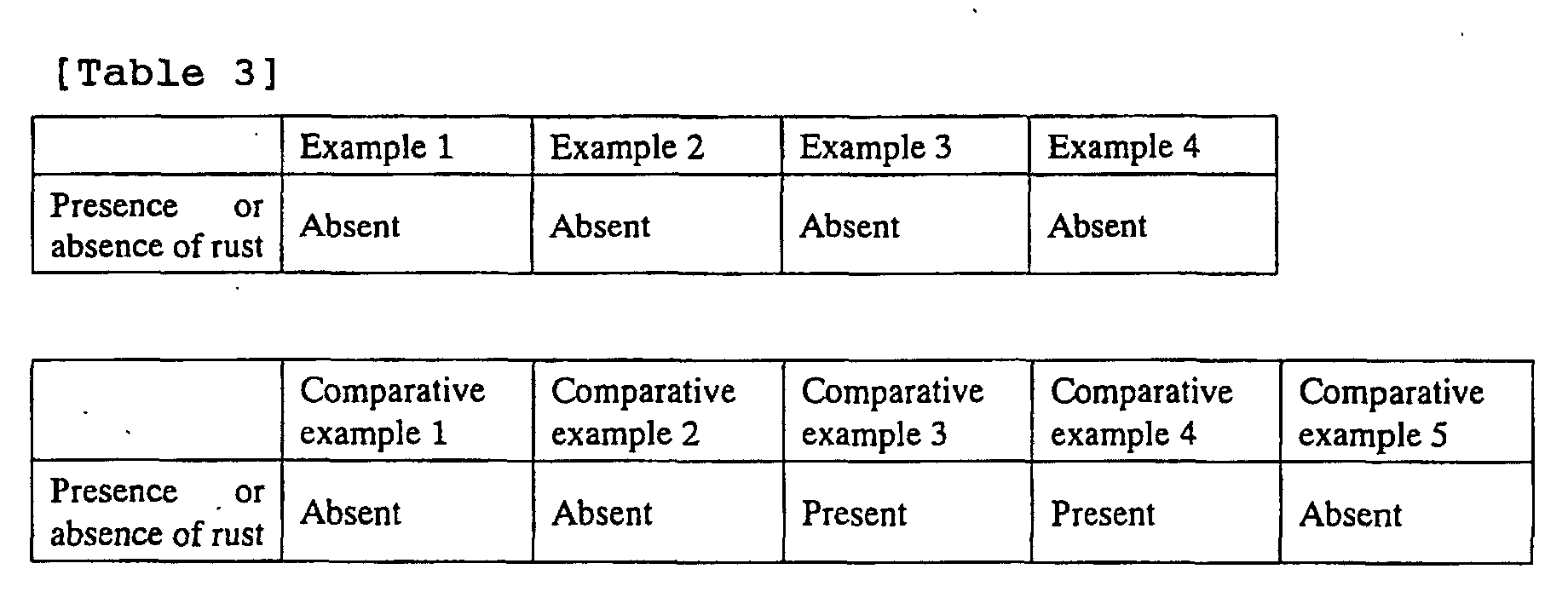
- the magnetic characteristics of the magnetic powder and magnet rollers used in examples and comparative examples are given in Tables 1 and 2, and the oxidation resistance was given in Table 3.
- the oxidation resistance after the manufactured magnet roller was left in air for 168 hours, the presence of rust on the surface of magnet roller was checked visually.
- the magnetic characteristics given in Tables 1 and 2 include “intrinsic coercive force iHc” and “residual magnetic flux density Br” of magnetic powder, “intrinsic coercive force iHc after molding” and “residual magnetic flux density Br” of magnet roller, “intensity of magnetic field for magnetization of main magnetic pole”, and “magnetic force of main magnetic pole” at points A to D after magnetization.
- the magnet roller made up of a conventional rare-earth bond magnet in comparative examples 3 and 4 when magnetization was effected in a strong magnetic field (30 KOe) as in comparative example 4, a magnetic force as high as 1350 G was obtained; however, when magnetization was effected in a weak magnetic field (15 KOe) as in comparative example 3, a magnetic force of only 700 G was obtained. Therefore, it was verified that the magnet rollers of these examples can provide a high magnetic force (850 G or higher) by means of magnetization effected in a weak magnetic field (15 KOe or lower).
- the body part thereof is made up of a rare-earth bond magnet made of rare-earth magnetic powder having a composite phase of a hard magnetic phase and a soft magnetic phase both magnetically exchange-interacting with each other and having a coercive force (iHc) of 5 KOe or lower and a residual magnetic flux density of 5 KG or higher, the low coercive force of soft magnetic phase and magnetization generally higher than the hard magnetic phase can be utilized, so that a high magnetic force can be obtained even if magnetization is effected in a weak magnetic field.
- iHc coercive force
- the main magnetic pole is formed by a single pole, even if magnetization is effected in a weak magnetic field of 8 to 15 KOe, a high magnetic force of 850 G or higher can be obtained. Also, even when the main magnetic pole is formed by a plurality of poles, a high magnetic force of 800 G or higher can be obtained. Therefore, a magnet roller having high development efficiency can be provided. Since the main magnetic pole can be magnetized in a weak magnetic field, the large size and high power of magnetizing apparatus can be avoided, so that a magnet roller having excellent magnetic characteristics can be provided while the manufacturing cost is kept low.
- a magnet roller that does not require a surface coating such as plating and has high corrosion resistance and oxidation resistance can be obtained, so that the magnet roller can have stable magnetic characteristics for a long period of time.
- the chain of developer near the main magnetic pole can be made dense at the time of use, and also the reversion (rotation) of developer caused by a change of magnetic polarity in the development zone is active, so that the supply efficiency of developer to a photosensitive material increases, which can achieve high picture quality.
Landscapes
- Physics & Mathematics (AREA)
- General Physics & Mathematics (AREA)
- Electromagnetism (AREA)
- Engineering & Computer Science (AREA)
- Power Engineering (AREA)
- Magnetic Brush Developing In Electrophotography (AREA)
Abstract
To provide a magnet roller having a high magnetic force
at low cost even if magnetized in a relatively weak magnetic
field, having a magnetic force (800 G or higher) sufficient
for development even if a plurality of magnetic poles are
provided in a main magnetic pole part, and having good
resistance to oxidation. The magnet roller (1) of the
present invention includes a body part (3) and a shaft part
(2) supporting both ends of (3). A plurality of magnetic
poles are provided in a magnetized manner in an outer
peripheral face of (3), made up of a rare-earth bond magnet
made of rare-earth magnetic powder having a composite phase
of a hard magnetic phase and a soft magnetic phase both
magnetically exchange-interacting with each other and having
a coercive force (iHc) of 5 KOe or lower and a residual
magnetic flux density (Br) of 5 KG or higher.
Description
The present invention relates to a magnet roller
incorporated in an electrophotographic device using an
electrophotographic process in an image forming apparatus
such as a copying machine, laser printer, or facsimile
receiving equipment or the like.
A magnet roller incorporated in an electrophotographic
device is used as a development roller which performs
development by supplying toner to an electrostatic latent
image carrier and visualizing an electrostatic latent image
or a cleaning roller which removes residual toner on the
electrostatic latent image carrier after the visualized
toner image is transferred to a sheet of paper. For example,
when a magnet roller is used as a development roller, as shown
in FIG. 9, a magnet roller 31 is constructed so that a body
part 33 thereof made of a magnet material is formed around
a shaft part 32, and is incorporated in a hollow cylindrical
sleeve 34 made of an aluminum alloy etc. In the outer
peripheral face of the body part 33 of the magnet roller 31
are provided a plurality of magnetic poles in a magnetized
manner. A magnetic pole having a highest surface magnetic
flux density of these magnetic poles is called a main magnetic
pole, and is often used as a development pole.
Conventionally, there has mainly been used a magnet roller
in which a main magnetic pole (development pole) consisting
of one magnetic pole is provided in the body part, and the
surface magnetic flux density curve (magnetic force
distribution curve) thereof exhibits a single high peak, or
a magnet roller in which two magnetic poles with the same
polarity are provided as main magnetic poles (development
poles), and the magnetic force distribution curve thereof
exhibits two high peaks (W peak).
The body part of the conventional magnet roller is made
up of a bond magnet that is formed by injection molding or
extrusion molding a material produced by mixing a resin
binder such as a thermoplastic resin with strontium-based
or barium-based ferrite magnetic powder or rare-earth
magnetic powder (typical examples are Nd-Fe-B based magnetic
powder and Sm-Co based magnetic powder). The magnetic
characteristics necessary for the magnet roller are provided
by applying an external magnetic field to the body part of
the magnet roller to magnetize it at the time of molding or
after the molding.
However, the conventional magnet roller mainly has
problems of the following items (1) to (4).
The present invention has been achieved to solve the
above problems, and accordingly an object thereof is to
provide a magnet roller capable of obtaining a high magnetic
force even if the magnet roller is magnetized in a relatively
weak magnetic field and capable of being produced at a low
cost. In particular, another object of the present invention
is to make the magnetic force of a main magnetic pole formed
by a single magnetic pole a high magnetic force of 850 G or
higher even if the magnet roller is magnetized in a weak
magnetic field of 15 KOe or lower and to make the magnetic
force of a main magnetic pole formed by a plurality of poles
at a practically sufficient level. At the same time, still
another object of the present invention is to provide a magnet
roller in which a surface coating such as plating is not needed,
and the corrosion resistance and oxidation resistance are
high.
To attain the above objects, the inventor paid attention
to a "nanocomposite magnet" made up of a soft magnetic
material having a low coercive force and a hard magnetic
material, in which the crystal grain size of the soft magnetic
material is on the order of nanometer, and carried out studies
earnestly on the magnet of this type. As a result, the
inventor found that the nanocomposite magnet is suitable as
a magnet material for a magnet roller, and came up with the
present invention.
Specifically, the present invention provides a magnet
roller comprising a body part and a shaft part supporting
both ends of the body part, in which a plurality of magnetic
poles are provided in a magnetized manner in the outer
peripheral face of the body part, wherein the whole or a part
of the body part is made up of a rare-earth bond magnet made
of rare-earth magnetic powder, having a composite phase of
a hard magnetic phase and a soft magnetic phase both
magnetically exchange-interacting with each other and having
a coercive force (iHc) of 5 KOe or lower and a residual
magnetic flux density of 5 KG or higher, and a resin binder.
Therefore, there can be obtained a magnet roller having
magnetic characteristics of a low coercive force (iHc)
provided by the presence of soft magnetic phase and a high
residual magnetic flux density (Br) provided by magnetic
exchange-interaction.
Also, the rare-earth magnetic powder preferably
consists of exchange spring magnetic powder. "Exchange
spring magnetism" is defined as a magnetic property that when
a large amount of soft magnetic phase exists in a magnet,
crystal grains of this soft magnetic phase and a hard magnetic
phase are connected to each other by magnetic exchange-interaction,
by which the magnetization of soft magnetic
phase, which intrinsically has only a low coercive force and
is easily reversed in a reverse magnetic field, becomes
difficult to reverse even in the reverse magnetic field, and
a mode looking as if both phases are connected to each other
by a spring and thus a single phase consisting of hard magnetic
phase only is exhibited (for example, see R. Coehoorn, K.
H. J. Buschow et al.: J. de Phys., 49 (1988) C8-669).
The rare-earth magnetic powder using rare-earth element
- iron - boron compound phase as the hard magnetic phase and
iron phase or iron - boron compound phase as the soft magnetic
phase, or the rare-earth magnetic powder using rare-earth
element - iron - nitrogen compound phase as the hard magnetic
phase and iron phase as the soft magnetic phase is suitable.
Since the rare-earth magnetic powder of this kind contains
a large amount of soft magnetic phase, the Curie point, which
is an index of temperature dependence of residual
magnetization, is mainly governed by the temperature
dependency of soft magnetic phase. Therefore, the Curie
point of the rare-earth magnetic powder takes a high value
of about 400°C or higher, and the temperature dependency of
residual magnetization becomes low, so that the use limit
temperature can be made as high as 200°C or higher.
Also, it is preferable that 1 to 16 wt% of cobalt (Co)
be added to the rare-earth magnetic powder. Thereby, a bond
magnet manufactured of the rare-earth magnetic powder is
caused to contain more Co than the conventional rare-earth
Nd - Fe - B based magnet consisting mainly of a hard magnetic
phase, so that the corrosion resistance and oxidation
resistance are increased, and also the occurrence of rust
etc. can be prevented without a surface coating such as
plating. Specifically, if the Co content is lower than 1 wt%,
the oxidation resistance etc. of the bond magnet decrease
so that rust etc. are liable to be formed. On the other hand,
if the Co content exceeds 16 wt%, the coercive force of the
bond magnet decreases, so that it is difficult to maintain
the magnetic characteristics necessary for the magnet
roller.
Also, when a main magnetic pole is formed by a plurality
of magnetic poles, it is preferable that the polarities of
the adjacent magnetic poles of the magnetic poles forming
the main magnetic pole be made reverse to each other. By
making the polarities of the adjacent magnetic poles reverse
to each other, the reversion (rotation) of developer caused
by a change of magnetic polarity in the development zone (a
zone in which developer chains toward a photosensitive
material on the main magnetic pole) is generated with a
rotation of the magnet roller in use, which offers an
advantage that the supply efficiency of developer to a
photosensitive material can be increased.
In order to control the magnetic force distribution of
magnet roller, it is preferable that a magnet piece made up
of the rare-earth bond magnet be provided in a groove formed
along the axis near the main magnetic pole in the outer
peripheral face of the body part. This rare-earth bond
magnet can be formed by a single or a plurality of magnet
pieces. When the main magnetic pole is formed by a plurality
of rare-earth bond magnet pieces, it is preferable that the
polarities of the adjacent rare-earth bond magnet pieces be
make reverse to each other.
Also, the magnet roller may be formed by bondedly
providing a plurality of magnet pieces each consisting of
the rare-earth bond magnet on the outer peripheral face of
the shaft part. For example, the magnet roller may be formed
by bonding magnet pieces having a C-shaped cross section,
which consist of the conventional ferrite resin magnet or
the like in the outer peripheral face of the shaft part, and
by fitting a single or a plurality of rare-earth bond magnet
pieces in a C-shaped opening portion (near the main magnetic
pole) of the magnet piece.
Embodiments of a magnet roller in accordance with the
present invention will now be described with reference to
the accompanying drawings.
Referring to the schematic sectional view of FIG. 1.
a magnet roller 1 in accordance with the present invention
is constructed so that a body part 3 is formed around a shaft
part 2 made of stainless steel, aluminum alloy, resin, or
the like. The body part 3 is made up of a rare-earth bond
magnet made of rare-earth magnetic powder having a composite
phase of a hard magnetic phase and a soft magnetic phase both
magnetically exchange-interacting with each other and having
a coercive force (iHc) of 5 KOe or lower and a residual
magnetic flux density (Br) of 5 KG or higher. The rare-earth
magnetic powder is preferably exchange spring magnetic
powder in which the crystal grain size of soft magnetic phase
is regulated to several tens of nanometers in order to make
the exchange-interaction effective. Also, a plurality of
magnetic poles (four poles of N1, S2, N2 and S1) are provided
in a magnetized manner in the outer peripheral face of the
body part 3. A magnetic pole having the highest magnetic
force, of these magnetic poles, is a main magnetic pole (N1
pole in this embodiment). Although four magnetic poles are
provided at equal intervals in this embodiment, the number
of poles and the position of pole are not subject to any
restriction in the present invention, and the number of poles
and the position of pole can be set appropriately according
to the desired magnetic characteristics; for example, five
poles or six poles may be provided.
As a magnet material for the body part 3 of the magnet
roller, a mixture in which 5 to 50 wt% of resin binder is
mixed with 50 to 95 wt% of rare-earth magnetic powder is used
as a main material, and as necessary, a silane-based or
titanate-based coupling agent serving as a surface treatment
agent of magnetic powder, an amide-based lubricant for
improving the flowability of molten magnet material, a
stabilizing agent for preventing the thermal decomposition
of resin binder, a flame retardant, or the like is preferably
added. If the content of the rare-earth magnetic powder is
less than 50 wt%, the magnetic characteristics of magnet
roller is decreased by a shortage of magnetic powder, so that
a desirable magnetic force (850 G or higher at the main
magnetic pole) is not obtained. If the content thereof
exceeds 95 wt%, binder falls short, so that the formability
of the body part 3 is impaired. Also, as the resin binder,
one kind or two or more kinds of ethylene-ethyl acrylate resin,
polyamide resin, polyethylene resin, polystyrene resin, PET
(polyethylene terephthalate), PBT (polybutylene
terephthalate), PPS (polyphenylene sulfide), EVA
(ethylene-vinyl acetate copolymer), EVOH (ethylene-vinylalcohol
copolymer), PVC (polyvinyl chloride), or the
like, or one kind or two or more kinds of epoxy resin, phenolic
resin, urea resin, melamine resin, furan resin, unsaturated
polyester resin, polyimde resin, and other thermosetting
resins can be used mixedly.
As the rare-earth magnetic powder, exchange spring
magnetic powder of rare earth element (R) - iron (Fe) -
nitrogen (N) alloy or rare earth element (R) - iron (Fe) -
boron (B) alloy containing a hard magnetic phase and a soft
magnetic phase is preferably used. Also, exchange spring
magnetic powder of rare earth element (R) - iron (Fe) - cobalt
(Co) alloy may be used. As the aforementioned R, Sm or Nd
is preferably used, and besides, one kind or two or more kinds
of Pr, Dy and Tb can be used combinedly. Also, in order to
enhance the magnetic characteristics by replacing some of
the aforementioned Fe, one or two or more kinds of elements
of Co, Ni, Cu, Zn, Ga, Ge, Al, Si, Sc, Ti, V, Cr, Mn, Zr,
Nb, Mo, Tc, Ru, Rh, Pd, Ag, Cd, In, Sn, Sb, Hf, Ta, W, Re,
Os, Ir, Pt, Au, Hg, Tl, Pb, Bi, etc. may be added. More
specifically, exchange spring magnetic powder such as
Nd-Fe-B based alloy (soft magnetic phase: Fe-B alloy, αFe),
Sm-Fe-N based alloy (soft magnetic phase: αFe), And Nd-Fe-Co-Cu-Nb-B
based alloy (soft magnetic phase: Fe-B alloy,
αFe etc.), and Nd-Fe-Co based alloy (soft magnetic phase:
αFe etc.) is suitable. In particular, from the viewpoint
of decreasing coercive force (iHc) and increasing residual
magnetic flux density (Br), exchange spring magnetic powder
of Nd4Fe80B20 alloy (soft magnetic phase: Fe3B, αFe) or Sm2Fe17N3
alloy (soft magnetic phase: αFe) is preferable.
Also, it is preferable that especially 1 to 16 wt% Co
and further 3 to 13 wt% Co be added to the aforementioned
exchange spring magnetic powder. For a bond magnet
manufactured by the rare-earth magnetic powder, the magnetic
characteristics are improved and the corrosion resistance
and oxidation resistance are increased by this addition of
Co, so that the formation of rust etc. can be restrained
without a surface coating on the outside surface thereof.
In order to manufacture the aforementioned exchange
spring magnetic powder, a rapid quenching method, mechanical
alloying method, or the like is used. Specifically, there
are cited a method in which each feedstock element is weighed,
alloy powder obtained by mechanical alloying is heat-treated,
and as necessary, nitriding treatment is performed, a method
in which each feedstock element is weighed, an alloy
containing an amorphous or near-amorphous microstructure
obtained by rapid quenching using the single roll method is
ground and then subjected to heat treatment to deposit
crystal, and as necessary, nitriding treatment is performed,
or the like methods. By properly controlling the quenching
conditions (rolling speed, etc.), grinding conditions, heat
treatment conditions (treatment time, temperature), or the
like conditions, exchange spring magnetic powder having a
soft magnetic phase with a crystal grain size of several tens
of nanometers can be manufactured. The aforementioned
nitriding treatment is necessary when R-Fe-N based exchange
spring magnetic powder is manufactured.
The magnet roller in accordance with the present
invention and a magnet piece described later are formed by
the extrusion molding method or the injection molding method
using pellets obtained by melting and kneading the
aforementioned magnet material. Alternatively, they may be
formed by the compression molding method using the
aforementioned magnet material. The magnetization of the
magnet roller and the magnet piece is provided by performing
oriented magnetization simultaneously with the injection
molding or extrusion molding, by performing magnetization
again after demagnetization performed once to remove
internal strain or to facilitate mold release, or by
performing magnetization after molding without oriented
magnetization at the time of molding. In forming and
assembling the magnet roller, the magnet roller can be formed
by integrally molding the body part and the shaft part thereof,
by installing the shaft part to both ends of the body part
or penetratingly installing the shaft part in the
cylindrically-shaped body part, or by bonding a magnet piece
formed into an irregular shape such as semicylindrical shape
or fan shape to the shaft part with a circular, elliptical,
or polygonal cross-sectional shape.
It is preferable that, for example, as shown in the
schematic sectional view of FIG. 2 (or FIG. 3), a magnet piece
7 (11) formed of the aforementioned rare-earth bond magnet
be provided in a groove 6 (10) formed along the axis near
the main magnetic pole in a body part 5 (9) of a magnet roller.
This magnet piece preferably is a square piece 7 having a
square shaped cross-section as shown in FIG. 2 or a semi-fan
shaped piece 11 having a semi-fan shaped cross section as
shown in FIG. 3. The piece having such a shape is easily made
common to a piece for another magnet roller, and also has
high formability and bondability.
When the main magnetic pole is composed of a plurality
of magnetic poles, as shown in the schematic sectional view
of FIG. 4, the main magnetic poles can be formed by forming
a body part 13 provided with a groove 14 having a fan-shaped
cross section, which is provided with a plurality of magnetic
poles (N pole, S pole, N pole, S pole) in the surface thereof,
on the outer peripheral face of a shaft part 12, and by
bondedly providing magnet pieces 15A, 15B and 15C consisting
of the aforementioned rare-earth bond magnet and each having
S pole, N pole, and S pole in the surface thereof in the groove
14 so that the magnetic polarities of the adjacent magnet
pieces are reverse to each other. Alternatively, as shown
in the schematic sectional view of FIG. 5, the main magnetic
poles can be formed by bonding a ferrite bond magnet 17 having
a C-shaped cross section, which is provided in a magnetized
manner with a plurality of magnetic poles (N pole, S pole,
N pole, S pole) in the surface thereof, to the outer peripheral
face of a shaft part 16, and by bondedly providing magnet
pieces 18A, 18B and 18C consisting of the aforementioned
rare-earth bond magnet and each having S pole, N pole, and
S pole in the surface thereof in a C-shaped opening portion
(near the main magnetic pole) of the ferrite bond magnet 17
so that the magnetic polarities of the adjacent magnet pieces
are reverse to each other.
Also, as shown in the schematic sectional view of FIG.
6, a magnet roller can be manufactured by bondedly providing
magnet pieces 21A, 21B and 21C consisting of the
aforementioned rare-earth bond magnet and each having S pole,
N pole, and S pole in the surface thereof on the outer
peripheral face of a shaft part 19 to form the main magnetic
poles, and by bonding ferrite bond magnet pieces 20A, 20B,
20A' and 20B' having other magnetic poles to the outer
peripheral face of the shaft part 19.
In the present invention, the shape of magnet piece is
not subject to any restriction, and the shape thereof can
be changed appropriately according to the desired magnetic
characteristics (magnetic force, magnetic force
distribution waveform, etc.). Also, in order to manufacture
the above-described magnet roller, what we call the two-color
molding method can be used in which two injection
molding machines are used, and after the body part is molded
by a first injection molding machine, the magnet piece is
molded in the groove by a second injection molding machine.
This method is effective in significantly simplifying the
manufacturing process.
As the magnetic field orientation of the magnet piece,
random orientation, straight orientation as indicated by the
arrows in FIGS. 2B and 3B, and radial orientation as indicated
by the arrows in FIGS. 2C and 3C are typical examples. Also,
not shown in the drawings, the magnetic force distribution
of magnet roller can be controlled by converging the magnetic
flux density of applied magnetic field to control the
oriented magnetization amount at any place on both side faces
and the back side face to the surface side face of the magnet
piece 7 (11). This control is effective, for example, when
the magnetic force distribution waveform in the main magnetic
pole is made asymmetric. Also, the magnet roller can be
formed by combining magnet pieces each having a different
orientation, and the combination may be selected
appropriately according to the required specification.
The use of isotropic magnetic powder as the rare-earth
magnetic powder in accordance with the present invention and
the magnetization of the magnet roller performed after
molding are desirable because a desired position of the
magnet roller is easily magnetized into a desired magnetic
force. In particular, since a magnetic circuit need not be
formed in the molding apparatus, the molding die is low in
cost. Also, since there is no deformation of bond magnet
caused by the applied magnetic field at the time of molding,
the dimensional accuracy after molding is high, so that
magnetization is easy to perform, and the pole position can
be set with high accuracy.
The following is a description of more specific examples
in accordance with the present invention and comparative
examples. The following examples do not impose any
restriction on the present invention.
The magnet roller of examples 1 to 3 and comparative
examples 1 to 4 described in detail below was manufactured
by mixing, melting, and kneading 10 wt% of resin binder (nylon
12) and 90 wt% of magnetic powder to form pellets, by forming
a roller (diameter: 13.6 mm, overall length: 320 mm) by
injection molding using these pellets, and then by applying
an external magnetic field to magnetize four poles (N1, S2,
N2, S1) as shown in FIG. 7. The magnetic force distribution
of this magnet roller was measured in a state of being
incorporated in a sleeve 22 made of an aluminum alloy. In
FIG. 7, the N1 pole is the main magnetic pole, and reference
numeral 23 denotes a shaft part, 24 denotes a body part, and
25 denotes a distribution waveform of magnetic force. Point
A designates the highest value of the magnetic force
distribution at the main magnetic pole.
A magnet roller was manufactured by mixing and kneading
nylon 12 used as a resin binder and exchange spring magnetic
powder of Nd4Fe80B20 (intrinsic coercive force iHc: 3.0 KOe,
residual magnetic flux density Br: 12 KG, Co content: 2 wt%)
used as magnetic powder to form pellets, by forming a roller
by injection molding, and then by magnetizing the roller with
an intensity of applied magnetic field of 8 to 15 KOe.
A magnet roller was manufactured by the same way as that
of example 1 except that exchange spring magnetic powder of
Nd5Fe71Co5Cu0.5Nb1B17.5 (intrinsic coercive force iHc: 4.8 KOe,
residual magnetic flux density Br: 5.2 KG, Co content: 6 wt%)
was used as magnetic powder.
A magnet roller was manufactured by the same way as that
of example 1 except that exchange spring magnetic powder of
Sm2Fe17N3 (coercive force iHc: 4.0 KOe, residual magnetic flux
density Br: 7.8 KG, Co content: 1 wt%) was used as magnetic
powder.
A magnet roller was manufactured by the same way as that
of example 1 except that ferrite magnetic powder of SrO·6Fe2O3
(coercive force iHc: 3 KOe, residual magnetic flux density
Br: 4.8 KG, Co content: 0 wt%) was used as magnetic powder.
A magnet roller was manufactured by the same way as that
of example 1 except that ferrite magnetic powder of SrO·6Fe2O3
(coercive force iHc: 3 KOe, residual magnetic flux density
Br: 4.8 KG, Co content: 0 wt%) was used as magnetic powder,
and the intensity of applied magnetic field was 20 to 30 KOe.
A magnet roller was manufactured by the same way as that
of example 1 except that rare-earth magnetic powder
(Nd13.5Fe1.7B4.8; coercive force iHc: 14 KOe, residual magnetic
flux density Br: 8.4 KG, Co content: 0.5 wt%) was used as
magnetic powder.
A magnet roller was manufactured by the same way as that
of example 1 except that rare-earth magnetic powder
(Nd13.5Fe1.7B4.8; coercive force iHc: 14 KOe, residual magnetic
flux density Br: 8.4 KG, Co content: 0.5 wt%) was used as
magnetic powder, and the intensity of applied magnetic field
was 20 to 30 KOe.
Next, a magnet roller of example 4 and comparative
example 5 described in detail below is formed by bonding
magnet pieces 29A to 29C, 28A, 28B, 28A' and 28B' to each
other on the outer peripheral face of a shaft part 26 as shown
in FIG. 8 (diameter: 13.6 mm, overall length: 320 mm). Each
of the magnet pieces was manufactured by mixing, melting,
and kneading 10 wt% of resin binder (nylon 12) and 90 wt%
of magnetic powder to form pellets, by molding the magnet
piece by injection molding using these pellets, and then by
applying an external magnetic field for magnetization after
the molding. In FIG. 8, the S1 pole, N1 pole, and S2 pole are
main magnetic poles, and reference character 26 denotes a
shaft part, 28A, 28B, 28A' and 28B' denote ferrite bond magnet
pieces, 29A to 29C denote rare-earth bond magnet pieces, and
30 denotes a magnetic force distribution waveform. Points
B, C and D designate the highest value of magnetic force
distribution at the main magnetic poles.
In FIG. 8, the pole-to-pole angle (2) between the
magnetic force peak position (point B) at the pole on the
upstream side of developer transfer and the magnetic force
peak position (point D) at the pole on the downstream side
of developer transfer was set at 60 degrees. Incidentally,
the pole-to-pole angle (1) between point B and point C is
30 degrees. If the pole-to-pole angle (2) between point B
and point D exceeds 60 degrees, the chain of developer near
point C which faces a photosensitive material is coarse,
which is the same as the state of chain in the development
zone of the conventional magnet roller. At the same time,
the reversion (rotation) of developer caused by a change of
magnetic polarity is inactive. Therefore, the amount of
toner supplied to the photosensitive material decreases, so
that high picture quality cannot be achieved. On the other
hand, if the pole-to-pole angle (2) is smaller than 30
degrees, a high magnetic force cannot be obtained even if
the aforementioned rare-earth bond magnet pieces are used
for the main magnetic pole part, and thus it was verified
that it is difficult to achieve high picture quality.
As magnetic powder for magnet pieces having the S1 pole,
N1 pole, and S2 pole, forming the main magnetic poles, exchange
spring magnetic powder of Nd4Fe80B20 (intrinsic coercive force
iHc: 3.0 KOe, residual magnetic flux density Br: 12 KG, Co
content: 2 wt%) was used, and as a resin binder, nylon 12
was used. Both of the materials were mixed and kneaded to
form pellets, and magnet pieces having a fan-shaped cross
section were formed by injection molding using these pellets.
After the magnet pieces were magnetized by applying an
external magnetic field, the magnet pieces were bonded to
each other on the outer peripheral face of the shaft part
26.
Also, as magnetic powder for magnet pieces having the
N2 pole, S3 pole, S4 pole, and N3 pole, forming magnetic poles
other than the main magnetic poles, ferrite magnetic powder
of SrO·6Fe2O3 (coercive force iHc: 3 KOe, residual magnetic
flux density Br: 4.8 KG) was used, and as a resin binder,
nylon 12 was used. Both of the materials were mixed and
kneaded to form pellets, and magnet pieces having a fan-shaped
cross section were formed by injection molding. After
oriented magnetization was effected simultaneously with the
molding, the magnet pieces were bonded to each other on the
outer peripheral face of the shaft part 26.
The exchange spring magnetic powder used for the magnet
pieces forming the main magnetic poles (S1 pole, N1 pole, and
S2 pole) in the above-described example 4 was changed to
ferrite magnetic powder of SrO·6Fe2O3 (coercive force iHc:
3 KOe, residual magnetic flux density Br: 4.8 KG, Co content:
0 wt%). This ferrite magnetic powder and nylon 12 were mixed
and kneaded to form pellets, and magnet pieces having a
fan-shaped cross section were formed by injection molding
using these pellets. Thereafter, a magnet roller was
manufactured in the same way as that of example 4 except that
oriented magnetization was effected simultaneously with the
molding.
The magnetic force distributions of the above-described
examples and comparative examples were measured by using a
gauss meter, by arranging probes in positions 1.2 mm distant
from the surface of magnet roller in the radial direction
(positions 8.0 mm distant from the center axis of magnet
roller in the radial direction), and by turning the magnet
roller in the circumferential direction. The magnetic
characteristics of the magnetic powder and magnet rollers
used in examples and comparative examples are given in Tables
1 and 2, and the oxidation resistance was given in Table 3.
Regarding the oxidation resistance, after the manufactured
magnet roller was left in air for 168 hours, the presence
of rust on the surface of magnet roller was checked visually.
The magnetic characteristics given in Tables 1 and 2 include
"intrinsic coercive force iHc" and "residual magnetic flux
density Br" of magnetic powder, "intrinsic coercive force
iHc after molding" and "residual magnetic flux density Br"
of magnet roller, "intensity of magnetic field for
magnetization of main magnetic pole", and "magnetic force
of main magnetic pole" at points A to D after magnetization.
| Magnetic characteristics of magnetic powder | Magnetic characteristics after molding | Intensity of magnetic field for magnetization of main magnetic pole (KOe) | Magnetic force of main magnetic pole (G) Point A | |||
| Coercive force iHc (KOe) | Residual magnetic flux density Br (KG) | Coercive force iHc (KOe) | Residual magnetic flux density Br (KG) | |||
| Example 1 | 3.0 | 12.0 | 3.0 | 7.0 | 15 | 1800 |
| Example 2 | 4.8 | 5.2 | 4.8 | 3.2 | 15 | 850 |
| Example 3 | 4.0 | 7.8 | 4.0 | 4.6 | 15 | 1200 |
| Comparative example 1 | 3.0 | 4.8 | 3.0 | 3.0 | 15 | 800 |
| Comparative example 2 | 3.0 | 4.8 | 3.0 | 3.0 | 30 | 800 |
| Comparative example 3 | 14.0 | 8.4 | 14.0 | 5.1 | 15 | 700 |
| Comparative example 4 | 14.0 | 8.4 | 14.0 | 5.1 | 30 | 1350 |
| Magnetic characteristics of magnetic powder | Magnetic characteristics after molding | Intensity of magnetic field for magnetization of main magnetic pole (KOe) | Magnetic force of main magnetic pole (G) | |||||
| Coercive force iHc (KOe) | Residual magnetic flux density Br (KG) | Coercive force iHc(KOe) | Residual magnetic flux density Br (KG) | Point B | Point C | Point D | ||
| Example 4 | 3.0 | 12.0 | 3.0 | 7.0 | 15.0 | 800 | 950 | 800 |
| Comparative example 5 | 3.0 | 4.8 | 3.0 | 3.0 | 15.0 | 450 | 550 | 450 |
As is apparent from the results given in Table 1, for
the magnet roller using exchange spring magnetic powder in
examples 1 to 3, when magnetization was effected in a weak
magnetic field (15 KOe), a magnetic force of 850 G or higher
was obtained in all of the examples; on the other hand, for
the magnet roller made up of a conventional ferrite bond
magnet in comparative examples 1 and 2, a magnetic force of
only 800 G was obtained even if magnetization was effected
in a weak magnetic field (15 KOe) or a strong magnetic field
(30 KOe). Also, for the magnet roller made up of a
conventional rare-earth bond magnet in comparative examples
3 and 4, when magnetization was effected in a strong magnetic
field (30 KOe) as in comparative example 4, a magnetic force
as high as 1350 G was obtained; however, when magnetization
was effected in a weak magnetic field (15 KOe) as in
comparative example 3, a magnetic force of only 700 G was
obtained. Therefore, it was verified that the magnet rollers
of these examples can provide a high magnetic force (850 G
or higher) by means of magnetization effected in a weak
magnetic field (15 KOe or lower).
Also, as is apparent from the results given in Table
3, in examples 1 to 3 in which exchange spring magnetic powder
was used and in comparative examples 1 and 2 in which
conventional ferrite magnetic powder was used, rust was not
formed at all; on the other hand, in comparative examples
3 and 4 in which rare-earth magnetic powder mainly consisting
of a hard magnetic phase, the occurrence of rust was
confirmed.
As is apparent from the results given in Table 2, in
example 4, the magnetic forces of all three poles
constituting the main magnetic pole were 800 G or higher;
on the other hand, in comparative example 5, the magnetic
forces of all three poles constituting the main magnetic pole
were only 600 G or lower. Therefore, it was verified that
for the magnet roller of example 4, even if the three magnetic
poles are arranged in the range of 60 degrees near the main
magnetic pole, a high magnetic force (800 G or higher) enough
for development can be obtained, and the chain of developer
near point C is dense.
Also, according to Table 3, in example 4 in which
exchange spring magnetic powder was used and in comparative
example 5 in which conventional ferrite magnetic powder was
used, rust was not formed at all.
According to the magnet roller in accordance with the
present invention, since the body part thereof is made up
of a rare-earth bond magnet made of rare-earth magnetic
powder having a composite phase of a hard magnetic phase and
a soft magnetic phase both magnetically exchange-interacting
with each other and having a coercive force (iHc) of 5 KOe
or lower and a residual magnetic flux density of 5 KG or higher,
the low coercive force of soft magnetic phase and
magnetization generally higher than the hard magnetic phase
can be utilized, so that a high magnetic force can be obtained
even if magnetization is effected in a weak magnetic field.
Especially when the main magnetic pole is formed by a single
pole, even if magnetization is effected in a weak magnetic
field of 8 to 15 KOe, a high magnetic force of 850 G or higher
can be obtained. Also, even when the main magnetic pole is
formed by a plurality of poles, a high magnetic force of 800
G or higher can be obtained. Therefore, a magnet roller
having high development efficiency can be provided. Since
the main magnetic pole can be magnetized in a weak magnetic
field, the large size and high power of magnetizing apparatus
can be avoided, so that a magnet roller having excellent
magnetic characteristics can be provided while the
manufacturing cost is kept low.
Also, by adding 1 to 16 wt% of cobalt to the rare-earth
magnetic powder, a magnet roller that does not require a
surface coating such as plating and has high corrosion
resistance and oxidation resistance can be obtained, so that
the magnet roller can have stable magnetic characteristics
for a long period of time.
Further, by forming the main magnetic pole by a plurality
of magnetic poles and making the polarities of adjacent
magnetic poles of the magnetic poles forming the main
magnetic pole reverse to each other, the chain of developer
near the main magnetic pole can be made dense at the time
of use, and also the reversion (rotation) of developer caused
by a change of magnetic polarity in the development zone is
active, so that the supply efficiency of developer to a
photosensitive material increases, which can achieve high
picture quality.
Claims (8)
- A magnet roller comprising:wherein the whole or a part of said body part is made up of a rare-earth bond magnet made of rare-earth magnetic powder, having a composite phase of a hard magnetic phase and a soft magnetic phase both magnetically exchange-interacting with each other and having a coercive force (iHc) of 5 KOe or lower and a residual magnetic flux density of 5 KG or higher, and a resin binder.a body part; anda shaft part,supporting both ends of said body part,in which a plurality of magnetic poles are provided in a magnetized manner in the outer peripheral face of said body part,
- The magnet roller according to claim 1, wherein said rare-earth magnetic powder consists of exchange spring magnetic powder.
- The magnet roller according to claim 1 or 2, wherein rare-earth element - iron - boron compound phase is used as said hard magnetic phase, and iron phase or iron - boron compound phase is used as said soft magnetic phase.
- The magnet roller according to claim 1 or 2, wherein rare-earth element - iron - nitrogen compound phase is used as said hard magnetic phase, and iron phase is used as said soft magnetic phase.
- The magnet roller according to any one of claims 1 to 4, wherein 1 to 16 wt% of cobalt is added to said rare-earth magnetic powder.
- The magnet roller according to any one of claims 1 to 5, wherein a main magnetic pole is formed by a plurality of magnetic poles, and the polarities of the adjacent magnetic poles of said magnetic poles forming said main magnetic pole are made reverse to each other.
- The magnet roller according to any one of claims 1 to 6, wherein a magnet piece made up of said rare-earth bond magnet is provided in a groove formed along the axis near the main magnetic pole in the outer peripheral face of said body part.
- The magnet roller according to any one of claims 1 to 6, wherein a plurality of magnet pieces each made up of said rare-earth bond magnet are bondedly provided on the outer peripheral face of said shaft part.
Applications Claiming Priority (3)
| Application Number | Priority Date | Filing Date | Title |
|---|---|---|---|
| JP2000000960 | 2000-01-06 | ||
| JP2000000960A JP2000323322A (en) | 1999-03-05 | 2000-01-06 | Magnet roller |
| PCT/JP2000/005939 WO2001052278A1 (en) | 2000-01-06 | 2000-09-01 | Magnet roller |
Publications (2)
| Publication Number | Publication Date |
|---|---|
| EP1253604A1 true EP1253604A1 (en) | 2002-10-30 |
| EP1253604A4 EP1253604A4 (en) | 2007-12-12 |
Family
ID=18530226
Family Applications (1)
| Application Number | Title | Priority Date | Filing Date |
|---|---|---|---|
| EP00956861A Withdrawn EP1253604A4 (en) | 2000-01-06 | 2000-09-01 | Magnet roller |
Country Status (2)
| Country | Link |
|---|---|
| EP (1) | EP1253604A4 (en) |
| WO (1) | WO2001052278A1 (en) |
Family Cites Families (3)
| Publication number | Priority date | Publication date | Assignee | Title |
|---|---|---|---|---|
| JPH0736282A (en) * | 1993-07-23 | 1995-02-07 | Hitachi Metals Ltd | Magnet roll |
| JPH1041128A (en) * | 1996-07-19 | 1998-02-13 | Bridgestone Corp | Magnet roller and its manufacturing method |
| JP2000003808A (en) * | 1997-12-02 | 2000-01-07 | Alps Electric Co Ltd | Hard magnetic material |
-
2000
- 2000-09-01 WO PCT/JP2000/005939 patent/WO2001052278A1/en not_active Ceased
- 2000-09-01 EP EP00956861A patent/EP1253604A4/en not_active Withdrawn
Also Published As
| Publication number | Publication date |
|---|---|
| WO2001052278A1 (en) | 2001-07-19 |
| EP1253604A4 (en) | 2007-12-12 |
Similar Documents
| Publication | Publication Date | Title |
|---|---|---|
| EP0128508B1 (en) | Method and apparatus for producing anisotropic magnets | |
| US6421519B1 (en) | Magnet roll having an anisotropic bonded magnet portion containing rare earth-iron-nitrogen magnet powder | |
| EP1152437A1 (en) | Magnet roller | |
| JP2000323322A (en) | Magnet roller | |
| JP3828369B2 (en) | Magnet roller | |
| US6703915B1 (en) | Magnet roller | |
| JP4032706B2 (en) | Magnet roller manufacturing method and magnet roller manufactured by the manufacturing method | |
| JP2002151324A (en) | Magnet roller | |
| JP2003086421A (en) | Magnet roller | |
| JP2004087644A (en) | Magnet roller | |
| JP2000298400A (en) | Magnet roller | |
| JP3564374B2 (en) | Magnet roller | |
| WO2001052278A1 (en) | Magnet roller | |
| JP2000331823A (en) | Magnet roller | |
| JP2005300935A (en) | Magnet roller or its manufacturing method | |
| JP2000305358A (en) | Magnet roller | |
| JP2001274015A (en) | Magnet roller | |
| JP3680648B2 (en) | Permanent magnet type motor and other permanent magnet application equipment | |
| JP2003015424A (en) | Magnet roller | |
| JP2000068120A (en) | Magnet roller | |
| JP2007027220A (en) | Resin magnet compact, manufacturing method thereof, and magnetizing yoke | |
| JP2001143923A (en) | Method of manufacturing magnet roller and method of manufacturing magnet piece | |
| JP2001142302A (en) | Magnet roller | |
| JP2003217924A (en) | Magnet roller | |
| JP4344193B2 (en) | Magnetic seal member and manufacturing method thereof |
Legal Events
| Date | Code | Title | Description |
|---|---|---|---|
| PUAI | Public reference made under article 153(3) epc to a published international application that has entered the european phase |
Free format text: ORIGINAL CODE: 0009012 |
|
| 17P | Request for examination filed |
Effective date: 20020801 |
|
| AK | Designated contracting states |
Kind code of ref document: A1 Designated state(s): AT BE CH CY DE DK ES FI FR GB GR IE IT LI LU MC NL PT SE |
|
| RBV | Designated contracting states (corrected) |
Designated state(s): AT BE CH CY DE FR GB IT LI NL |
|
| A4 | Supplementary search report drawn up and despatched |
Effective date: 20071112 |
|
| 17Q | First examination report despatched |
Effective date: 20080225 |
|
| STAA | Information on the status of an ep patent application or granted ep patent |
Free format text: STATUS: THE APPLICATION IS DEEMED TO BE WITHDRAWN |
|
| 18D | Application deemed to be withdrawn |
Effective date: 20080708 |