BACKGROUND OF THE PRESENT INVENTION
Field of the present invention
The present invention relates to an optical information recording
medium, and more particularly to an optical information recording
medium capable of recording and replaying information by irradiation of
laser light.
Description of the Related Art
A high-density optical information recording medium (DVD) that
records and reproduces a large amount of text information, image
information and sound information is increasingly demanded. In
particular, in order to accommodate picture recording for digital HDTV
broadcast, further increase of a recording density of an optical recording
medium is earnestly studied. Increase of the recording density has been
attained, for example, by shortening a wavelength of laser light used for
recording and replaying on an optical recording medium, or by increasing
an aperture (NA) of an objective lens of an optical system of an apparatus
for recording and replaying. Under these circumstances, blue-violet
lasers have been put on the market.
There is a phase change-type optical disk known as a DVD, which
employs an alloy layer, such as GeSbTe, as a recording layer. The
recording layer is heated for a moment with laser light to cause a phase
change from a crystalline state to an amorphous state. A change in
reflection coefficient due to the phase change is utilized for recording and
replaying. In recent years, a DVD system has been reported
("ISOM2000", pp. 210 to 211) in which recording and replaying are
carried out with a blue-violet laser by using the phase change-type
recording layer. The demand for high density recording has been
attained to a certain extent by this system, but there is a problem that the
durability of the recording layer to repeated replaying is insufficient.
A recordable DVD (DVD-R) that can record information only once
is also known among DVDs. The DVD-R has a basic constitution of an
optical disk including a substrate having grooves and, formed thereon, a
recording layer, a reflective layer and a protective layer. In general,
structures are known in which such optical disks each having a
substrate with a reflective layer and a protective layer are attached to
each other at the sides of the protective layers with an adhesive, or such
an optical disk and an optical disk formed with a single substrate are
attached to each other. Additionally, a constitution is also known in
which a reflective layer, a recording layer and a cover layer are provided
on a substrate in this order, and recording and replaying with laser light
are carried out on the side of the cover layer.
Red laser light having a wavelength of 635 or 650 nm is generally
used for recording and replaying of the DVD-R. However, there is an
increasing demand for recording density on DVD-Rs. In order to attain
high density recording, recording and replaying with laser light having a
shorter wavelength instead of the red laser light become necessary. In
order to attain high density recording of the DVD-R, the use of laser light
of a shorter wavelength and the use of an objective lens of a higher NA
have been considered.
In general, the energy of light increases inversely proportionally to
the wavelength, and when the wavelength of laser light is decreased for
high density recording of an optical disk, the light energy applied to the
optical disk is increased. In particular, DVD-R uses a layer of an organic
substance as a recording layer, and therefore the recording layer is
deteriorated upon repeated irradiation with light for replaying (replaying
deterioration), causing a problem in durability. Reduction of the laser
output has been considered, but the reflection is lowered when the
replaying output is decreased, which causes problems of reduction in RF
output, reduction in C/N (carrier to noise ratio), and reduction in
reproducing durability.
Another optical information recording medium (optical disk) that
can record information only once with laser light has also been known.
This optical disk is referred to as a recordable CD ("CD-R"), and a
representative structure thereof includes a transparent disk substrate
having laminated thereon a recording layer formed with an organic
substance, a reflective layer formed with a metal such as gold, and a
protective layer formed with resin, in this order. Recording of
information on the CD-R is carried out by irradiation with laser light in
the near infrared region (which is generally laser light having a
wavelength around 780 nm), and the recording is attained by a
mechanism in which the temperature of an irradiated part of the
recording layer is locally increased by absorbing the light, and the optical
characteristics of that part are changed by a physical or chemical change
(such as formation of a pit), so as to attain recording of information. The
reading of information (replaying) is carried out by irradiation on the
CD-R with laser light of the same wavelength as the laser light for
recording, and a change in reflectivity between parts of the recording
layer having the changed optical characteristics (recorded part) and parts
having the unchanged optical characteristics (unrecorded part) is
detected, so as to attain replaying.
In recent years, an optical information recording medium having a
higher recording density has been demanded. In order to deal with this
demand, the optical disk referred to as a recordable digital versatile disk
("DVD-R") has been demanded (described, for example, in "NIKKEI NEW
MEDIA", additional volume "DVD", published 1995). In the structure of
the DVD-R, the two disks, each containing a transparent disk substrate,
generally have guide grooves (also referred to as grooves or pregrooves) for
tracking irradiated laser light which are formed with a small half-value
width (0.74 to 0.8 µm), which is less than a half of that of the CD-R, and
a recording layer containing an organic substance, the reflective layer
and protective layer laminated on the substrate in this order, and are
attached to each other with the recording layers turned inside, or are
attached to each other with the recording layers turned inside with a disk
protective substrate interposed therebetween. Because recording and
replaying of the DVD-R is carried out by irradiating with visible laser light
(which is generally laser light having a wavelength in a range from 630 to
680 nm), recording with a higher density than the CD-R can be attained.
Networks, such as the Internet, and high resolution TV are
quickly spreading these days. Test broadcasts of HDTV (high definition
television) have recently started. Under the circumstances, a recording
medium of a large capacity is demanded that can easily record image
information at low cost. The DVD-R sufficiently achieves the role of the
large capacity recording medium under the current situation, but there is
constantly increasing demand for larger capacity and higher density
recording media, and it is necessary to develop a recording medium that
can deal with these demands. Accordingly, development of a recording
medium having a larger capacity, which can attain high density recording
with light having a shorter wavelength than that for the DVD-R, is being
continued.
For example, JP-A No. 4-74690, No. 7-304256, No. 7-304257, No.
8-127174, No. 11-53758, No. 11-334204, No. 11-334205, No. 11-334206,
No. 11-334207, No. 2000-43423, No. 2000-108513, No. 2000-113504,
No. 2000-149320, No. 2000-158818 and No. 2000-228028 disclose
methods for recording and replaying, in which an optical information
recording medium having a recording layer containing an organic
substance is irradiated with laser light of a wavelength of 530 nm or less
from the side of the recording layer toward the reflective layer, so as to
attain recording and replaying of information. In these methods, an
optical disk having a recording layer containing a substance such as a
porphyrin compound, an azo organic substance, a metallic azo organic
substance, a quinophthalone organic substance, a trimethylcyanine
organic substance, an organic substance having a dicyanobiphenyl
skeleton, a coumarin compound or a naphthalocyanine compound is
irradiated with blue laser light (wavelength: 430 nm or 488 nm) or blue-green
laser light (wavelength: 515 nm), so as to attain recording and
replaying of information.
In order to attain compatibility with the CD-R system that is
currently used, an optical information recording medium has been
proposed that can attain recording and replaying with two kinds of laser
light having different wavelengths. For example, JP-A No. 2000-141900,
No. 2000-158816, No. 2000-185471, No. 2000-289342 and No.
2000-309165 propose such optical information recording media that can
attain recording and replaying with either laser light of the near infrared
region around 780 nm or visible laser light around 650 nm by using a
mixture of an organic material used in CD-R and an organic material
used in DVD-Rs.
However, according to investigations performed by the present
inventors, the optical disks disclosed in the publications noted in the
foregoing require further improvements, because they cannot provide the
sensitivity that is practically demanded to record information by
irradiation of laser light of a short wavelength from 380 to 500 nm, and
other recording characteristics, such as reflectivity and a modulation
degree, are also insufficient. In particular, the optical disks disclosed in
the publications noted in the foregoing show lowered recording
characteristics upon irradiation with laser light having a wavelength of
from 380 to 500 nm.
SUMMARY OF THE PRESENT INVENTION
The present invention has been developed taking the foregoing
problems into consideration, and an object thereof is to provide an optical
recording medium that is excellent in both C/N (carrier to noise ratio) and
reproducing durability and can attain high density recording without any
problem.
Another object of the present invention is to provide an optical
information recording medium that can attain recording and replaying in
a high density by irradiation of blue laser light of a short wavelength of
from 380 to 500 nm to exhibit excellent recording characteristics.
The foregoing objects are attained by the following optical
recording media of the present invention.
The present invention relates to, as a first aspect, an optical
recording medium including a substrate including an organic substance
with at least one maximum absorption peak in each of a range from 600
to 800 nm and a range from 300 to 400 nm, the substrate including a
groove that includes a track pitch of from 200 to 400 nm, a groove depth
of from 50 to 150 nm and a groove half-value width of from 90 to 200 nm;
a reflective layer on the substrate; a recording layer on the reflective layer;
and a cover layer on the recording layer, wherein the medium is
recordable and replayable using laser light including a wavelength of 450
nm or less and an objective lens including an aperture NA of 0.7 or more.
The present invention also relates to, as a second aspect, an
optical recording medium including a substrate including an organic
substance with at least one maximum absorption peak in each of a range
from 600 to 800 nm and a range from 300 to 400 nm, the substrate
including a groove that includes a track pitch of from 200 to 400 nm, a
groove depth of from 50 to 150 nm and a groove half-value width of from
90 to 200 nm; a reflective layer on the substrate; and a recording layer on
the reflective layer, wherein the medium is recordable and replayable
using laser light including a wavelength of 450 nm or less and an
objective lens including an aperture NA that is at least 0.5 and less than
0.7.
The present invention further relates to, as a third aspect, an
optical information recording medium including a substrate including a
groove depth of from 15 to 45 nm, a track pitch of from 250 to 400 nm, a
groove half-value width of from 60 to 200 nm and a groove tilt angle of
from 40° to 80°; a reflective layer on the substrate; a recording layer
including an organic substance on the reflective layer, at which recording
layer information is recordable and replayable by irradiating laser light
including a wavelength of from 380 to 500 nm through a lens including
an aperture NA of 0.7 or more; and a sheet layer on the recording layer.
BRIEF DESCRIPTION OF THE DRAWING
Fig. 1 is a cross sectional view showing a cross section in a radial
direction of grooves of a substrate of an optical information recording
medium according to a third aspect of the present invention.
DESCRIPTION OF THE PREFERRED EMBODIMENTS
An embodiment of the first aspect of the present invention will be
described below.
An optical recording medium of the present invention includes a
substrate having particular grooves having thereon a layer structure
including a reflective layer, a recording layer and a cover layer provided in
this order. Recording and replaying are carried out through the cover
layer. The cover layer is adhered on the recording layer with an
adhesive.
The substrate is provided with grooves, particularly grooves in a
spiral form. The grooves have a track pitch of from 200 to 400 nm, a
depth of from 50 to 150 nm and a half-value width of from 90 to 200 nm.
As the recording layer, a recording layer is used that contains an organic
substance having at least one maximum absorption peak in each of a
range from 600 to 800 nm and a range from 300 to 400 nm.
The recording and replaying of the optical recording medium is
carried out by using laser light having a wavelength of 450 nm or less and
an objective lens having an aperture (NA) of 0.7 or more.
In the optical recording medium of the present invention, because
the recording layer having the particular organic substance is provided
on the substrate having the particular grooves formed thereon, it is
excellent in both C/N (carrier to noise ratio) and reproducing durability,
and can carry out high density recording without any problem.
Examples of the material of the substrate used in the optical
recording medium include plastic substrates, such as polycarbonate,
acrylic resin (e.g., polymethyl methacrylate), vinyl chloride resin (e.g.,
polyvinyl chloride or vinyl chloride copolymer), epoxy resin, amorphous
polyolefin, polyester, and the like. Among these, polycarbonate is
preferably used.
The recording layer formed in the optical recording medium of the
present invention is principally formed as an organic substance recording
layer. Known organic substances can be used without any limitation.
The organic substances have such characteristics that they have at least
one maximum absorption peak in each of a range from 600 to 800 nm
and a range from 300 to 400 nm. Specifically, preferred examples
thereof include organic substances disclosed in JP-A No. 4-74690, No.
8-127174, No. 11-53758, No. 11-334204, No. 11-334205, No. 11-334206,
No. 11-334207, No. 2000-43423, No. 2000-108513 and No.
2000-158818, and triazol, triazine, cyanine, merocyanine,
aminobutadiene, phthalocyanine, cinnamic acid, viologen, azo,
oxonolbenzoxazole and benzotriazole organic compounds. More
preferred examples thereof include cyanine, aminobutadiene,
benzotriazole, phthalocyanine and rhodocyanine series organic
compounds. Among these, phthalocyanine organic compounds having
at least one maximum absorption peak in each of a range from 600 to 700
nm and a range from 300 to 400 nm are particularly preferred.
The formation of the organic substance recording layer is carried
out by dissolving the organic substance and, depending on necessity,
various kinds of additives such as a discoloration preventing agent, a
binder, an antioxidant, a UV absorbent, a plasticizer and a lubricant in a
solvent to prepare a coating composition, and the coating composition is
coated on the surface of the substrate to prepare a coated film, which is
then dried. Upon dissolving the organic substance and the discoloration
preventing agent and the like in the solvent, it is preferred to carry out an
ultrasonic dispersion treatment for complete dissolution. Examples of
the solvent of the coating composition for the organic substance layer
include esters, such as butyl acetate and cellosolve acetate, ketones,
such as methyl ethyl ketone, cyclohexanone and methyl isobutyl ketone,
chlorinated hydrocarbons, such as dichloromethane, 1,2-dichloroethane
and chloroform, amides, such as dimethylformamide, hydrocarbons,
such as cyclohexane, ethers, such as tetrahydrofuran, ethyl ether and
dioxane, alcohols, such as ethanol, n-propanol, isopropanol, n-butanol
and diacetone alcohol, fluorine solvents, such as
2,2,3,3-tetrafluoropropanol, and glycol ethers, such as ethylene glycol
monomethyl ether, ethylene glycol monoethyl ether and propylene glycol
monomethyl ether. The solvent may be used singly or as a combination
of two or more of these, taking the solubility of the organic substance to
be used into consideration.
Examples of the binder include natural organic polymer
substances, such as gelatin, cellulose derivative, dextran, rosin and
rubber, hydrocarbon resins, such as polyurethane, polyethylene,
polypropylene, polystyrene and polyisobutylene, vinyl resins, such as
polyvinyl chloride, polyvinylidene chloride and vinyl chloride-vinyl
acetate copolymer, acrylic resins, such as polymethyl acrylate and
polymethyl methacrylate, and synthetic organic polymers, such as
polyvinyl alcohol, chlorinated polyethylene, epoxy resin, butyral resin,
rubber derivatives and phenol-formaldehyde resin. In the case where
the binder is used as the material of the organic substance recording
layer, the usage amount of the binder is generally from 0.2 to 20 parts by
weight, preferably from 0.5 to 10 parts by weight and more preferably
from 1 to 5 parts by weight, per 100 parts by weight of the organic
substance.
The concentration of the organic substance in the coating
composition thus prepared is generally in a range from 0.01 to 10% by
weight, and preferably in a range from 0.1 to 5% by weight.
Examples of the coating method include a spraying method, a
spin coating method, a dipping method, a roll coating method, a blade
coating method, a doctor roll method and a screen printing method. The
spin coating method is preferably employed because fluctuation of the
film thickness of the organic substance film in the circumferential
direction can be reduced, to form a uniform film. The organic substance
recording layer may be a single layer or may have a multilayer structure.
The thickness of the organic substance recording layer is generally in a
range from 20 to 500 nm, and preferably in a range from 50 to 300 nm.
The coating temperature of the organic substance coating
composition may be in a range from 23 to 50°C without any problem, and
it is preferably from 24 to 40°C, and more preferably from 25 to 37°C.
The reflective layer formed in the optical recording medium of the
present invention may be any reflective layer as long as it is a reflective
layer having a high reflectivity to laser light, i.e., a reflectivity of 70% or
more. Examples thereof include a metal or a metalloid, such as Mg, Se,
Y, Ti, Zr, Hf, V, Nb, Ta, Cr, Mo, W, Mn, Re, Fe, Co, Ni, Ru, Rh, Pd, Ir, Pt,
Cu, Ag, Au, Zn, Cd, Al, Ga, In, Si, Ge, Te, Pb, Po, Sn, Bi, and stainless
steel. Among these, a reflective film containing Au or Ag is preferred,
with a reflective film containing Ag or Au as a main component being
particularly preferred.
The reflective layer can be formed on the organic substance
recording layer, for example, by subjecting a light-reflective substance to
vacuum deposition, sputtering or ion plating. The thickness of the
light-reflective layer is generally in a range from 10 to 800 nm, preferably
in a range from 20 to 500 nm, and more preferably in a range from 50 to
300 nm.
The cover layer in the present invention may be any resin sheet
having a transmittance of the laser light used for recording and replaying
of 80% or more and a surface roughness of 5 nm or less. Examples of
the material therefor include polycarbonate (PUREACE produced by
Teijin Ltd. and PANLITE produced by Teijin Chemicals Ltd.), cellulose
triacetate (FUJI TACK produced by Fuji Photo Film Co., Ltd.) and PET
(LUMIRROR produced by Toray Industries, Inc.). Among these,
polycarbonate and cellulose triacetate are preferably used.
The cover layer is adhered to the recording layer with an adhesive.
The adhesive is selected in consideration of the adhesion strength and
workability, and a radiation-curable adhesive is preferably used.
Examples of the radiation-curable adhesive include electron beam-curable
adhesives and ultraviolet ray-curable adhesives.
The radiation-curable adhesive contains a monomer or a resin
having two or more radiation-sensitive double bonds in the molecule, and
examples thereof include an acrylate, an acrylamide, a methacrylate, a
methacrylamide, an allyl compound, a vinyl ether and a vinyl ester.
Preferred examples thereof include an at least bi-functional acrylate
compound and an at least bi-functional methacrylate compound.
Specific examples of the at least bi-functional (meth)acrylate
compound that can be used in the present invention include compounds
formed by adding acrylic acid or methacrylic acid to an aliphatic diol,
such as ethylene glycol diacrylate, propylene glycol diacrylate, butanediol
diacrylate, hexanediol diacrylate, diethylene glycol diacrylate, triethylene
glycol diacrylate, tetraethylene glycol diacrylate, neopentyl glycol
diacrylate, tripropylene glycol diacrylate, ethylene glycol dimethacrylate,
propylene glycol dimethacrylate, butanediol dimethacrylate, hexanediol
dimethacrylate, diethylene glycol dimethacrylate, triethylene glycol
dimethacrylate, tetraethylene glycol dimethacrylate, neopentyl glycol
dimethacrylate and tripropylene glycol dimethacrylate.
A polyether acrylate or polyether methacrylate formed by adding
acrylic acid or methacrylic acid to a polyether polyol, such as
polyethylene glycol, polypropylene glycol or polytetramethylene glycol, or
a polyester acrylate or polyester methacrylate formed by adding acrylic
acid or methacrylic acid to a known polyester polyol obtained from a
dibasic acid and glycol can also be used.
A polyurethane acrylate or polyurethane methacrylate formed by
adding acrylic acid or methacrylic acid to a known polyurethane formed
from a polyol and a polyisocyanate can be used.
A compound obtained by adding acrylic acid or methacrylic acid
to bisphenol A, bisphenol F, hydrogenated bisphenol A, hydrogenated
bisphenol F or an alkyleneoxide adduct thereof, or a compound having a
cyclic structure, such as isocyanuric acid alkylene oxide-modified
diacrylate, isocyanuric acid alkylene oxide-modified dimethacrylate,
tricyclodecane dimethanol diacrylate or tricyclodecane dimethanol
dimethacrylate, can also be used.
In the case where an ultraviolet ray-curable adhesive is used as
the radiation-curable adhesive, a photopolymerization initiator is
necessarily added to the polymerizable monomer and the resin. Known
photopolymerization initiators can be used therefor, and among these, an
aromatic ketone compound is preferred. The aromatic ketone
compound is not particularly limited, and those having relatively large
extinction coefficients at wavelengths of 254, 313 and 365 nm, at which
bright line spectra of a mercury lamp that is generally used as an
ultraviolet ray irradiation light source are preferable. Representative
examples thereof include acetophenone, benzophenone, benzoin ethyl
ether, benzyl methyl ketal, benzyl ethyl ketal, benzoin isobutyl ketone,
hydroxydimethyl phenyl ketone, 1-hydroxycyclohexyl phenyl ketone,
2,2-diethoxyacetophenone and Michler's ketone, and various other kinds
of ketones may be used.
The mixing ratio of the aromatic ketone compound is generally
from 0.5 to 20 parts by weight, preferably from 2 to 15 parts by weight,
and more preferably from 3 to 10 parts by weight, per 100 parts by weight
of the polymerizable monomer and the resin. An ultraviolet ray-curable
adhesive having a photoinitiator mixed therein is commercially available
and may be used in the present invention. A mercury lamp is used as
the ultraviolet ray light source. A lamp of 20 to 200 W/cm is used as the
mercury lamp at a rate of from 0.3 to 20 m/min. In general, the distance
between the cover layer and the mercury lamp is preferably from 1 to 30
cm.
As an electron beam accelerator used for the electron beam-curable
adhesive, a scanning system, a double scanning system and a
curtain beam system can be employed, and a curtain beam system is
preferably used because high output can be obtained at relatively low
cost. The electron beam characteristics are: an accelerating voltage of
from 100 to 1,000 kV, preferably from 150 to 300 kV; and an absorption
dose of from 0.5 to 20 Mrad, preferably from 1 to 10 Mrad.
A method for coating the adhesive onto the recording layer is not
particularly limited, but a spin coating method is preferred. The
thickness of the adhesive layer is preferably about from 5 to 50 µm. The
coating temperature of the adhesive may be in a range from 23 to 50°C
without any problem, and it is preferably from 24 to 40°C, and more
preferably from 25 to 37°C.
An embodiment of the second aspect of the present invention will
be described below.
The optical recording medium of the present invention includes a
substrate having particular grooves and provided thereon a layer
structure including a recording layer and a reflective layer in this order.
The substrate has grooves, particularly grooves in a spiral form,
and the grooves have a track pitch of from 200 to 400 nm, a depth of from
50 to 150 nm and a half-value width of from 90 to 200 nm. The
recording layer contains an organic substance having at least one
maximum absorption peak in each of a range from 600 to 800 nm and a
range from 300 to 400 nm.
The optical recording medium carries out recording and replaying
by using laser light having a wavelength of 450 nm or less and an
objective lens having an aperture (NA) of from 0.5 to 0.7.
The optical recording medium of the present invention is excellent
in both the C/N and the reproducing durability and can carry out high
density recording without any problem because of the particular organic
substance recording layer provided on the substrate with the particular
grooves formed therein.
According to the second aspect of the present invention, it is
preferred that the optical recording medium (hereinafter sometimes
referred to as a first optical disk), which has the substrate having
provided thereon the recording layer and reflective layer, is adhered to a
second disk having at least a substrate. The second disk may be either a
single substrate layer or a substrate having a reflective layer provided
thereon. The first and second disks may have a protective layer and a
printed layer provided thereon. The first optical disk and the second
disk are adhered with an adhesive.
The material of the substrate, the material of the recording layer,
the method for forming the organic substance recording layer, the solvent
for the coating composition of the organic substance layer, the binder, the
concentration of the organic substance in the coating composition, the
coating method and the like used in the optical recording medium
according to the second aspect of the present invention may be the same
as those described for the first aspect of the present invention.
The reflective layer formed in the optical recording medium
according to the second aspect of the present invention may be formed
with the same materials by the same methods as those described for the
first aspect of the present invention. The thickness of the light-reflective
layer is generally in a range from 10 to 800 nm, preferably in a range from
20 to 500 nm, and more preferably in a range from 50 to 300 nm.
An adhesive for adhering the first and second optical disks is
selected in consideration of the adhesion strength and workability, and a
radiation-curable adhesive is preferably used. Examples of the
radiation-curable adhesive include electron beam-curable adhesives and
ultraviolet ray-curable adhesives.
The radiation-curable adhesive and the photopolymerization
initiator may be the same as those described for the first aspect of the
present invention.
The electron beam accelerator used for the radiation-curable
adhesive and the like may also be the same as those described for the
first aspect of the present invention.
An embodiment of the third aspect of the present invention will be
described in detail below.
The optical information recording medium of the present
invention is an optical information recording medium including a
substrate having thereon a recording layer capable of carrying out
recording of information by irradiation with laser light having a
wavelength of from 380 to 500 nm through a lens having an aperture (NA)
of 0.7 or more. A reflective layer is provided on the substrate, the
recording layer is provided on the reflective layer, and a sheet layer is
provided on the recording layer. The recording layer is a layer
containing an organic substance, and the substrate has grooves with a
depth of from 15 to 45 nm, a track pitch of from 250 to 400 nm, a half-value
width of from 60 to 200 nm and a tilt angle of from 40 to 80°.
Organic Substance Recording Layer
The recording layer of the optical information recording medium
includes a layer of an organic substance (which is also referred to as an
organic coloring material). Laser light having a wavelength of from 380
to 500 nm is condensed by passing through a lens having an NA
(aperture) of 0.7 or more, and the recording layer is irradiated therewith
at the position of a focal point, whereby the temperature of the irradiated
part of the organic substance layer is locally increased by absorbing the
light, and the optical characteristics of that part are changed by a
physical or chemical change (such as formation of a pit) to attain
recording of information. Reading of information (replaying) is generally
carried out by irradiation of the optical disk with laser light of the same
wavelength as the laser light for recording, and a difference in reflectivity
between parts of the recording layer having the changed optical
characteristics (recorded part) and parts having the unchanged optical
characteristics (unrecorded part) is detected to attain replaying.
It is preferred that the organic substance constituting the
recording layer of the present invention contains a phthalocyanine
derivative and/or a benzotriazole derivative, because a recording medium
of large capacity and high density can then be obtained.
Phthalocyanine Derivative
The phthalocyanine derivative used in the organic substance
recording layer of the medium is preferably a compound represented by
the following general formula (I).
In the general formula (I), R represents a substituent and n
represents an integer from 1 to 8. If n is 2 or more, the plurality of
groups represented by R may be the same as each other or different from
each other. M represents two hydrogen atoms, a metal, a metallic oxide
or a metal having a ligand.
In the general formula (I), preferred examples of the groups
represented by R include an alkyl group having from 1 to 20 carbon
atoms, an aryl group having from 6 to 14 carbon atoms, an aralkyl group
having from 7 to 15 carbon atoms, a heterocyclic group having from 1 to
10 carbon atoms, an alkoxy group having from 1 to 20 carbon atoms, an
aryloxy group having from 6 to 14 carbon atoms, an acyl group having
from 2 to 21 carbon atoms, a sulfonyl group having from 2 to 21 carbon
atoms, a carbamoyl group having from 1 to 25 carbon atoms, a sulfamoyl
group having from 0 to 32 carbon atoms, an alkoxycarbonyl group having
from 1 to 20 carbon atoms, an aryloxycarbonyl group having from 7 to 15
carbon atoms, an acylamino group having from 2 to 21 carbon atoms, a
sulfonylamino group having from 1 to 20 carbon atoms and a halogen
atom. More preferred examples among these include an alkyl group
having from 3 to 16 carbon atoms, an aryl group having from 6 to 10
carbon atoms, an alkoxy group having from 3 to 16 carbon atoms, an
aryloxy group having from 6 to 10 carbon atoms, a sulfonyl group having
from 3 to 16 carbon atoms and a sulfamoyl group having from 2 to 20
carbon atoms, and further preferred examples include an alkoxy group
having from 4 to 12 carbon atoms, a sulfonyl group having from 4 to 12
carbon atoms and a sulfamoyl group having from 4 to 16 carbon atoms,
with a sulfamoyl group having from 6 to 12 carbon atoms being
particularly preferred.
In the general formula (I), the substituent represented by R may
further have a substituent, and examples of this substituent include the
following.
Examples of this substituent include a linear or cyclic alkyl group having
from 1 to 20 carbon atoms (such as methyl, ethyl, isopropyl and
cyclohexyl), an aryl group having from 6 to 18 carbon atoms (such as
phenyl, chlorophenyl, 2,4-di-t-amylphenyl and 1-naphtyl), an aralkyl
group having from 7 to 18 carbon atoms (such as benzyl and anisyl), an
alkenyl group having from 2 to 20 carbon atoms (such as vinyl and
2-methylvinyl), an alkynyl group having from 2 to 20 carbon atoms (such
as ethynyl, 2-methylethynyl and 2-phenylethynyl), a halogen atom (such
as F, Cl, Br and I), a cyano group, a hydroxyl group, a carboxyl group, an
acyl group having from 2 to 20 carbon atoms (such as acetyl, benzoyl,
salicyloyl and pivaloyl), an alkoxy group having from 1 to 20 carbon
atoms (such as methoxy, butoxy and cyclohexyloxy), an aryloxy group
having from 6 to 20 carbon atoms (such as phenoxy, 1-naphthoxy and
toluoyl), an alkylthio group having from 1 to 20 carbon atoms (such as
methylthio, butylthio, benzylthio and 3-methoxypropylthio), an arylthio
group having from 6 to 20 carbon atoms (such as phenylthio and
4-chlorophenylthio), an alkylsulfonyl group having from 1 to 20 carbon
atoms (such as methanesulfonyl and butanesulfonyl), an arylsulfonyl
group having from 6 to 20 carbon atoms (such as benzenesulfonyl and
p-toluenesulfonyl), a carbamoyl group having from 1 to 17 carbon atoms
(such as unsubstituted carbamoyl, methylcarbamoyl, ethylcarbamoyl,
n-butylcarbamoyl and dimethylcarbamoyl), an amide group having from
1 to 16 carbon atoms (such as acetamide and benzamide), an acyloxy
group having from 2 to 10 carbon atoms (such as acetoxy and
benzoyloxy), an alkoxycarbonyl group having from 2 to 10 carbon atoms
(such as methoxycarbonyl and ethoxycarbonyl), and a 5- or 6-membered
heterocyclic group (such as an aromatic heterocyclic ring, e.g., pyridyl,
thienyl, furil, thiazolyl, imidazolyl and pyrazolyl, a pyrrolidine ring, a
piperidine ring, a morpholine ring, a pyran ring, a thiopyran ring, a
dioxane ring and a dithiolan ring).
Preferred examples of the substituent on the substituent
represented by R in the general formula (I) include a linear or cyclic alkyl
group having from 1 to 16 carbon atoms, an aryl group having from 6 to
14 carbon atoms, an aralkyl group having from 7 to 15 carbon atoms, an
alkoxy group having from 1 to 16 carbon atoms, an aryloxy group having
from 6 to 14 carbon atoms, a halogen atom, an alkoxycarbonyl group
having from 2 to 17 carbon atoms, a carbamoyl group having from 1 to 10
carbon atoms and an amide group having from 1 to 10 carbon atoms, and
among these, more preferred examples include a linear or cyclic alkyl
group having from 1 to 10 carbon atoms, an aralkyl group having from 7
to 13 carbon atoms, an aryl group having from 6 to 10 carbon atoms, an
alkoxy group having from 1 to 10 carbon atoms, an aryloxy group having
from 6 to 10 carbon atoms, a chlorine atom, an alkoxycarbonyl group
having from 2 to 11 carbon atoms, a carbamoyl group having from 1 to 7
carbon atoms and an amide group having from 1 to 8 carbon atoms. A
linear or cyclic alkyl group having from 3 to 10 carbon atoms, an aralkyl
group having from 7 to 11 carbon atoms, an alkoxy group having from 1
to 8 carbon atoms, an alkoxycarbonyl group having from 3 to 9 carbon
atoms, a phenyl group and a chlorine atom are particularly preferred.
In the general formula (I), n is preferably from 2 to 6, more
preferably 3 or 4, and particularly preferably 4. When n is an integer of
2 or more, plural groups represented by R may be the same as each other
or different from each other, and are preferably the same as each other.
In the general formula (I), M is preferably a metal, and copper, nickel and
palladium are more preferred. Among these, copper and nickel are
further preferred, and copper is particularly preferred.
The compound represented by the general formula (I) may form a
multimer through bonds at arbitrary positions, and the plural units of
the multimer may be the same as each other or different from each other
and may be bonded to a polymer chain, such as polystyrene, polymethyl
methacrylate, polyvinyl alcohol or cellulose.
The phthalocyanine derivative represented by the general formula
(I) used in the medium may be used singly as a particular derivative or
may be used as a mixture of plural kinds thereof having structures
different from each other, and is preferably used singly. There are some
cases where the phthalocyanine derivative represented by the general
formula (I) unavoidably contains substitutional position isomers of the
substituent represented by R upon synthesis thereof, but the
substitutional position isomers need not be distinguished from each
other and can be considered as the same derivative. Furthermore, in the
case where isomers with respect to the substituent represented by R are
contained, they need not be distinguished from each other and can be
considered as the same phthalocyanine derivative. Accordingly, cases
where the structures are different from each other mean that, in the
general formula (I), the species or numbers of the constitutional atoms of
the substituent represented by R are different, or the integer represented
by n is different.
Preferred specific examples of the phthalocyanine derivative used
in the present invention are shown in Table 1 below, but the present
invention is not limited thereto. The numerals of the substituent
position of the substituent represented by R in the phthalocyanine
derivative are shown in the formula below.

| Specific Examples of Phthalocyanine Derivatives used in the present invention |
| No. | Substitution position - R | M |
| (I-1) | 2,9,16,23-SO2N(i-C4H9-i)2 | Cu |
| (I-2) | 2,9,16,23-SO2NH-(2-butoxyphenyl) | Cu |
| (I-3) | 2,9,16,23-SO2NH(CH2)3O-(2,4-di-t-amylphenyl) | Cu |
| (I-4) | 2,9,16,23-SO2N-(2-ethoxyethyl)2 | Ni |
| (I-5) | 2,9,16,23-SO2N-(cyclohexyl)2 | Ni |
| (I-6) | 2,9,16,23-SO2N(phenyl)2 | Ni |
| (1-7) | 2,9,16,23-SO2NH(2-i-propyloxycarbonylphenyl) | Pd |
| (I-8) | 2,9,16,23-SO2NH(2,6-di-i-propylphenyl) | Pd |
| (I-9) | 2,9,16,23-SO2-(4-morpholinyl) | Co |
| (I-10) | 2,9,16,23-SO2NMe-(3-chlorophenyl) | Fe |
| (I-11) | 2,9,16-SO2N(CH2)3NMe2 | Cu |
| (I-12) | 2,9,16,23-SO2-(2-butoxyphenyl) | Cu |
| (I-13) | 2,9,16,23-SO2-(2-ethoxy-5-t-butyl) | Ni |
| (I-14) | 2,9,16,23-SO2-(2-ethoxycarbonylphenyl) | Co |
| (I-15) | 2,9,16,23-SO2(CH2)4-(2,4-di-t-amylphenoxy) | Cu |
| (I-16) | 2,9,16,23-SO2(CH2)2OEt | Pd |
| (I-17) | 2,9,16,23-SO2(cyclohexyl) | Cu |
| (I-18) | 2,9,16,23-SO2-(4-i-butyrylaminophenyl) | Ni |
| (I-19) | 2,9,16-SO2-(3,5-dichlorophenyl) | Pd |
| (I-20) | 2,9,16-SO2CH2CO2-CH2CH(Et)C4H9 | Mg |
| (I-21) | 3,10,17,24-Me2,9,16,23-SO2-(2-methoxyphenyl) | Zn |
| (I-22) | 1,8,15,22-SO2N(C5H7)2 | Cu |
| (I-23) | 1,8,15,22-OCH(CHMe2)2 | Ni |
| (I-24) | 1,8,15,22-OCHMe(phenyl) | Zn |
| (1-25) | 1,4,8,11,15,18,22,26-i-propyloxy | Cu |
| (I-26) | 2,3,9,10,16,17,23,24-(2-methoxyethoxy) | SiCl2 |
| (I-27) | 2,9,16,23-t-amyl | Ni |
| (I-28) | 2,9,16,23-(2,6-di-methoxyphenyl) | Zn |
| (I-29) | 1,8,15,22-(1-naphtyl) | Pd |
| (1-30) | 2,9,16,23-cumyl | Cu |
| (I-31) | 2,9,16,23-(4-cumylphenoxy) | Co |
| (I-32) | 1,8,15,22-s-butoxy2,9,16,23-Cl | Pd |
[Table 1]
The phthalocyanine derivative used in the present invention can
be synthesized by methods described or cited by Shirai and Kobayashi,
"Phthalocyanines - chemistry and function", pp. 1 to 62 (published by
IPC) and C.C. Lenznoff and A.B.P. Lever, "Phthalocyanines - Properties
and Applications", pp. 1 to 54 (published by VCH), and analogous
methods.
Benzotriazole Derivative
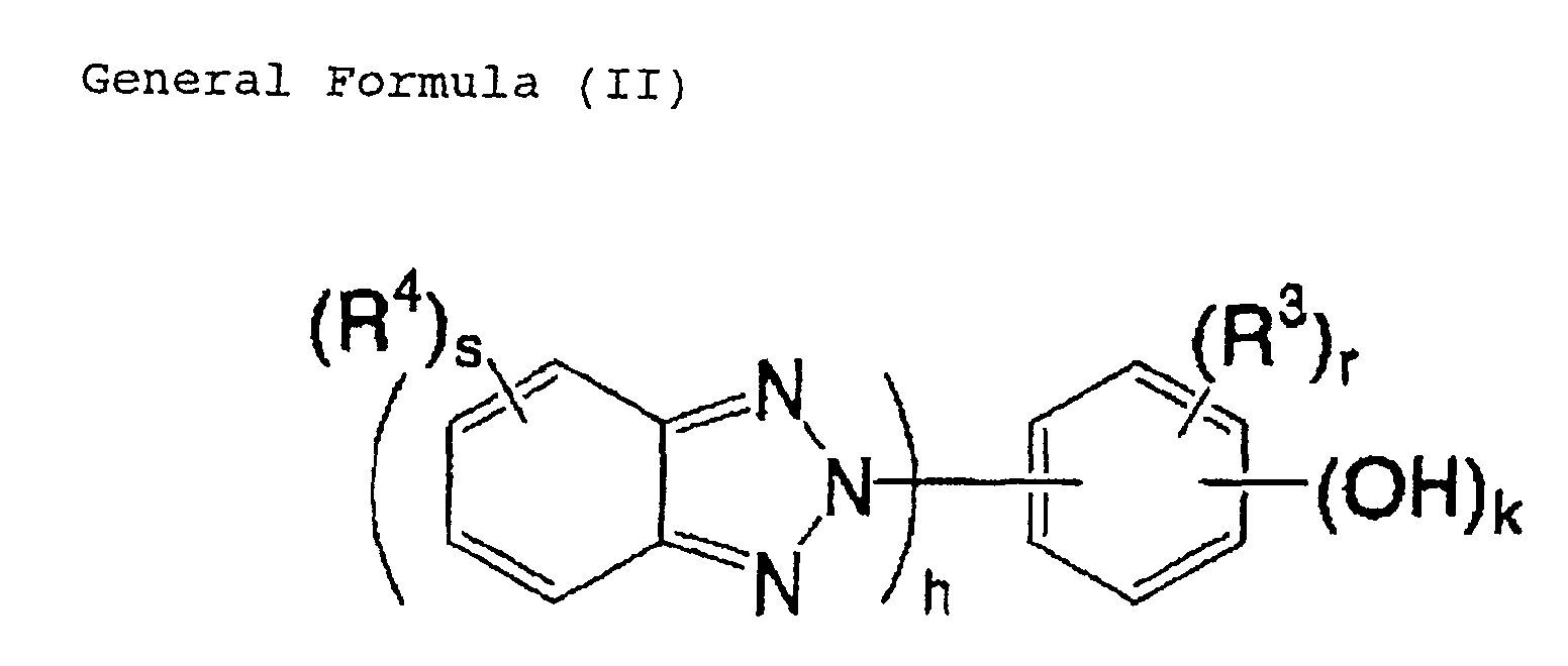
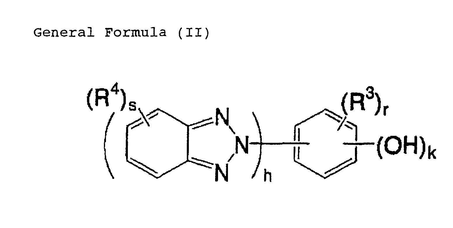
The benzotriazole derivative used in the organic substance
recording layer of the medium is preferably a compound represented by
the following general formula (II).
In the general formula (II), h and k each independently represents
an integer from 1 to 3, R3 and R4 each represents a substituent, and r and
s each represents an integer from 0 to 3. If h = 1 and r ≠ 0, R3 and R4
represent substituents selected from the group consisting of an alkyl
group having from 2 to 16 carbon atoms, an aryl group having from 6 to
14 carbon atoms, an aralkyl group having from 7 to 15 carbon atoms, an
alkoxy group having from 1 to 16 carbon atoms, an aryloxy group having
from 6 to 14 carbon atoms, an alkoxycarbonyl group having from 2 to 17
carbon atoms, a carbamoyl group having from 1 to 10 carbon atoms, an
amide group having from 1 to 10 carbon atoms, an acyloxy group having
from 2 to 17 carbon atoms and a halogen atom.
The benzotriazole derivative represented by the general formula
(II) is a compound in which a benzene ring is substituted by at least a
hydroxyl group and the nitrogen atom at the 2-position of a
1,2,3-benzotriazolyl group.
In the general formula (II), h represents the number of
1,2,3-benzotriazolyl groups, and h is an integer from 1 to 3, preferably 1
or 2, and particularly preferably 1. The symbol k represents the number
of hydroxyl groups, and k is an integer from 1 to 3, preferably 1 or 2, and
particularly preferably 1. It is preferred that the 1,2,3-benzotriazolyl
group and the hydroxyl group are substituted to adjacent positions of the
benzene ring.
In the general formula (II), R3 is a substituent on the benzene ring,
and R4 is a substituent on the 1,2,3-benzotriazolyl ring. The symbol r
represents the number of substituents represented by R3, and r is an
integer from 0 to 3, preferably 1 or 2, and particularly preferably 1. The
symbol s represents the number of substituents represented by R4, and s
is an integer from 0 to 3, preferably 0 or 1, and particularly preferably 0.
In other words, it is preferred that the benzene ring substituted with a
hydroxyl group has another substituent, and it is also preferred that the
1,2,3-benzotriazolyl ring is unsubstituted.
In the general formula (II), examples of the substituents
represented by R3 and R4 include the following.
Examples of the substituents include a linear or cyclic alkyl group
having from 1 to 20 carbon atoms (such as methyl, ethyl, isopropyl and
cyclohexyl), an aryl group having from 6 to 18 carbon atoms (such as
phenyl, chlorophenyl, 2,4-di-t-amylphenyl and 1-naphtyl), an aralkyl
group having from 7 to 18 carbon atoms (such as benzyl and anisyl), an
alkenyl group having from 2 to 20 carbon atoms (such as vinyl and
2-methylvinyl), an alkynyl group having from 2 to 20 carbon atoms (such
as ethynyl, 2-methylethynyl and 2-phenylethynyl), a halogen atom (such
as F, Cl, Br and I), a cyano group, a hydroxyl group, a carboxyl group, an
acyl group having from 2 to 20 carbon atoms (such as acetyl, benzoyl,
salicyloyl and pivaloyl), an alkoxy group having from 1 to 20 carbon
atoms (such as methoxy, butoxy and cyclohexyloxy), an aryloxy group
having from 6 to 20 carbon atoms (such as phenoxy, 1-naphthoxy and
toluoyl), an alkylthio group having from 1 to 20 carbon atoms (such as
methylthio, butylthio, benzylthio and 3-methoxypropylthio), an arylthio
group having from 6 to 20 carbon atoms (such as phenylthio and
4-chlorophenylthio), an alkylsulfonyl group having from 1 to 20 carbon
atoms (such as methanesulfonyl and butanesulfonyl), an arylsulfonyl
group having from 6 to 20 carbon atoms (such as benzenesulfonyl and
p-toluenesulfonyl), a carbamoyl group having from 1 to 17 carbon atoms
(such as unsubstituted carbamoyl, methylcarbamoyl, ethylcarbamoyl,
n-butylcarbamoyl and dimethylcarbamoyl), an amide group having from
1 to 16 carbon atoms (such as acetamide and benzamide), an acyloxy
group having from 2 to 20 carbon atoms (such as acetoxy and
benzoyloxy), an alkoxycarbonyl group having from 2 to 20 carbon atoms
(such as methoxycarbonyl and ethoxycarbonyl), and a 5- or 6-membered
heterocyclic group (such as an aromatic heterocyclic ring, e.g., pyridyl,
thienyl, furil, thiazolyl, imidazolyl and pyrazolyl, a pyrrolidine ring, a
piperidine ring, a morpholine ring, a pyran ring, a thiopyran ring, a
dioxane ring and a dithiolan ring). Groups derived from 1,3-dimethyl
barbituric acid are not included in examples of a substituent represented
by R3 or R4.
Preferred examples of the substituent represented by R3 or R4
include a linear or cyclic alkyl group having from 2 to 16 carbon atoms,
an aryl group having from 6 to 14 carbon atoms, an aralkyl group having
from 7 to 15 carbon atoms, an alkoxy group having from 1 to 16 carbon
atoms, an aryloxy group having from 6 to 14 carbon atoms, a halogen
atom, an alkoxycarbonyl group having from 2 to 17 carbon atoms, a
carbamoyl group having from 1 to 10 carbon atoms and an amide group
having from 1 to 10 carbon atoms, and among these, more preferred
examples include a linear or cyclic alkyl group having from 2 to 10 carbon
atoms, an aralkyl group having from 7 to 13 carbon atoms, an aryl group
having from 6 to 10 carbon atoms, an alkoxy group having from 2 to 10
carbon atoms, an acyloxy group having from 2 to 17 carbon atoms, an
aryloxy group having from 6 to 10 carbon atoms, a chlorine atom, an
alkoxycarbonyl group having from 2 to 11 carbon atoms, a carbamoyl
group having from 2 to 7 carbon atoms and an amide group having from
2 to 8 carbon atoms, with a linear or cyclic alkyl group having from 3 to
10 carbon atoms, an aralkyl group having from 7 to 11 carbon atoms, an
alkoxy group having from 2 to 8 carbon atoms, an alkoxycarbonyl group
having from 3 to 9 carbon atoms, a phenyl group and a chlorine atom
being particularly preferred.
When h = 1 and r ≠ 0, the substituent represented by R3 is
particularly preferably an alkyl group having from 2 to 16 carbon atoms,
an aryl group having from 6 to 14 carbon atoms, an aralkyl group having
from 7 to 15 carbon atoms, an alkoxy group having from 1 to 16 carbon
atoms, an aryloxy group having from 6 to 14 carbon atoms, an
alkoxycarbonyl group having from 2 to 17 carbon atoms, a carbamoyl
group having from 1 to 10 carbon atoms, an amide group having from 1
to 10 carbon atoms, an acyloxy group having from 2 to 17 carbon atoms
or a halogen atom.
The substituent represented by R3 or R4 may further have a
substituent and, in this case, examples of the substituent include those
groups exemplified for the substituent represented by R3 or R4. R3 may
be a divalent or trivalent linking group and may be substituted on plural
benzene rings. The plural benzene rings substituted by the group
represented by R3 may be further substituted with different substituents.
The compound represented by the general formula (II) may form a
multimer through direct or indirect bonding at arbitrary positions, and
the plural units of the multimer may be the same as each other or
different from each other. The cases where a multimer is formed by
indirect bonding at arbitrary positions include the case where the units
are bonded by the substitucnt represented by R3 or R4 as a linking group.
The units may be bonded to a polymer chain, such as polystyrene,
polymethacrylate, polyvinyl alcohol or cellulose.
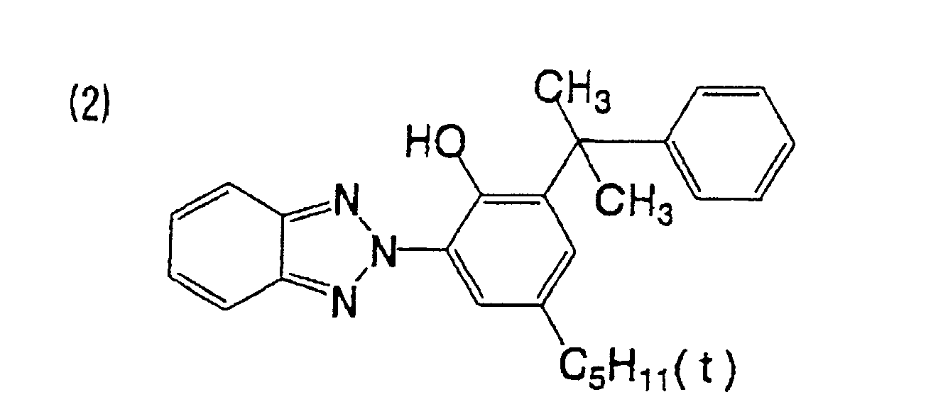
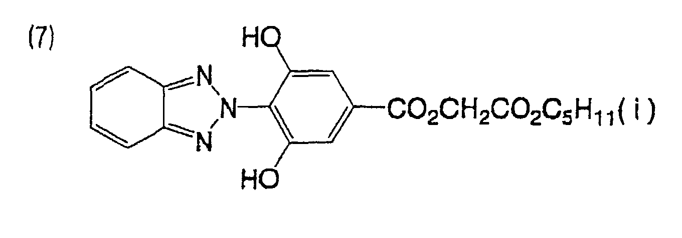
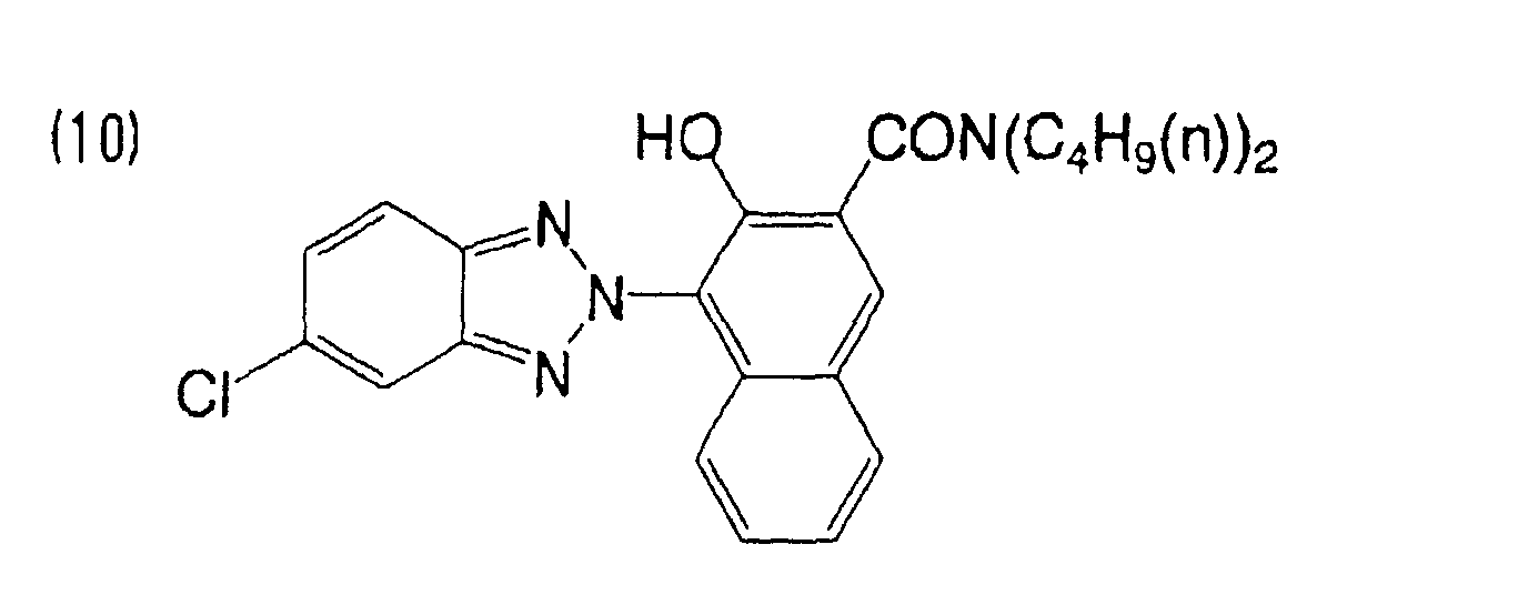
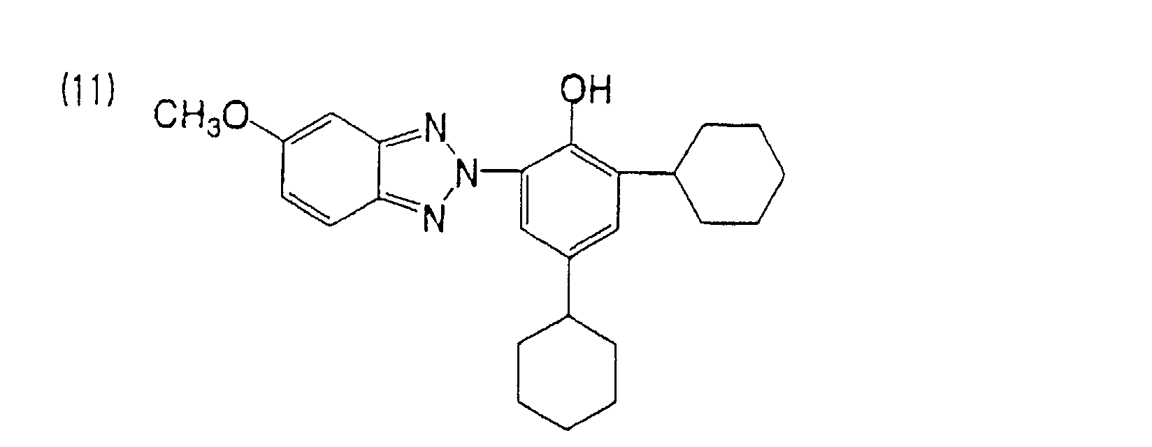
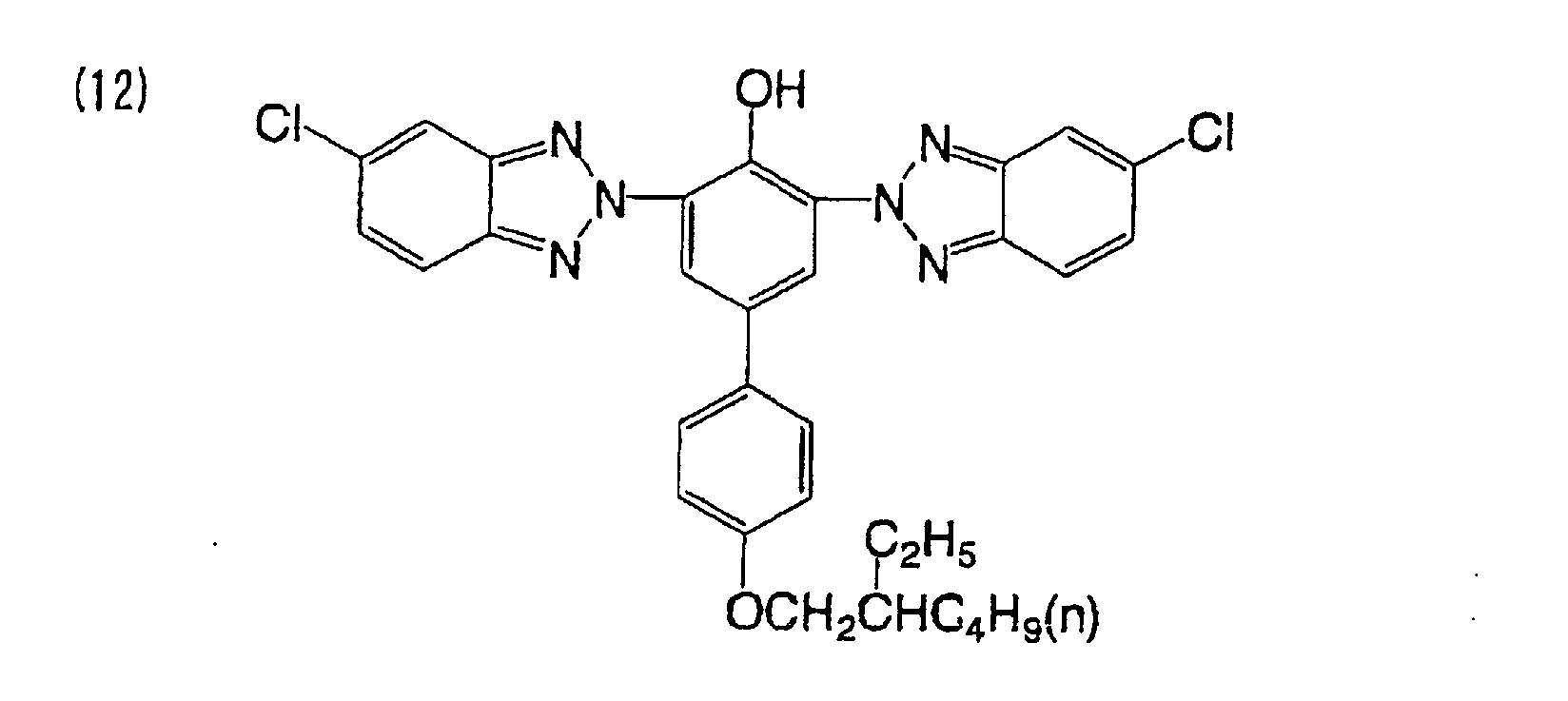
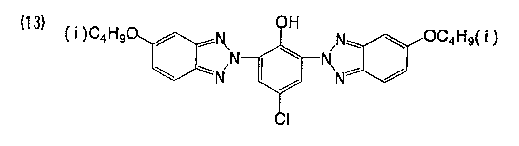
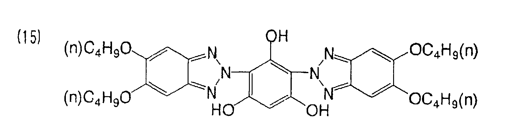
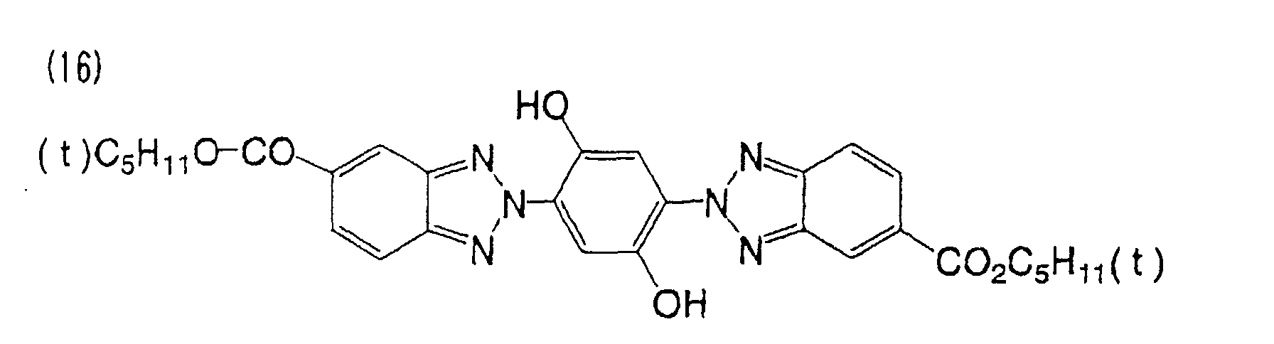
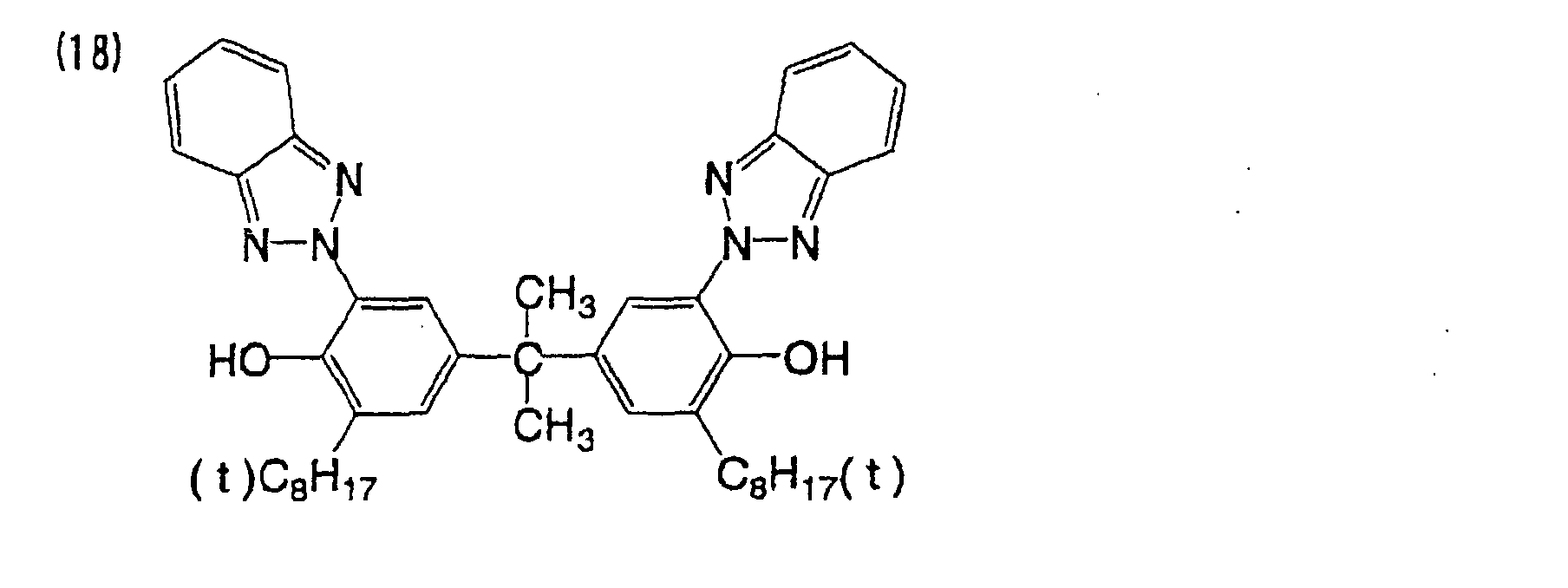
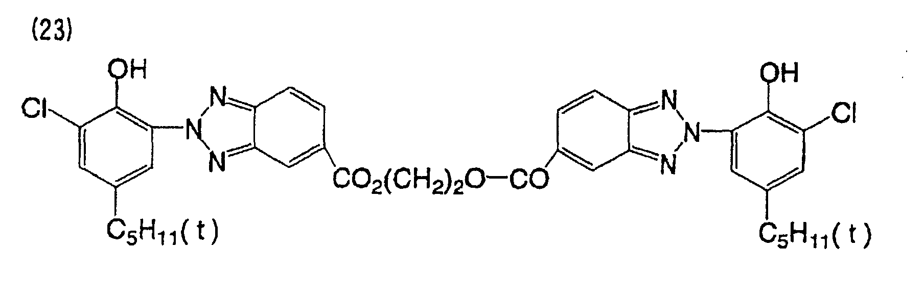
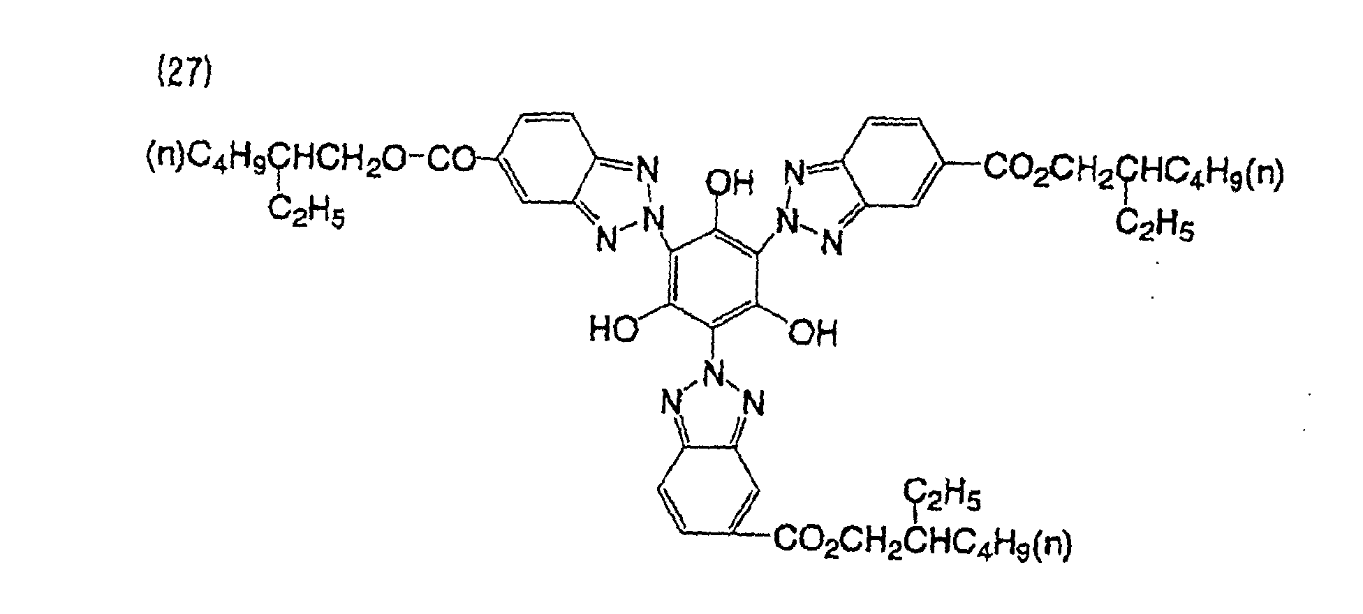
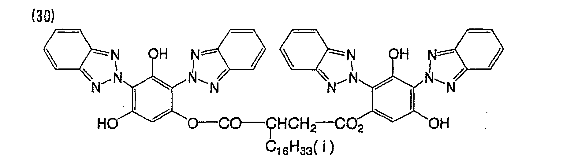
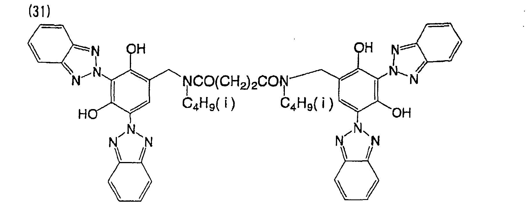
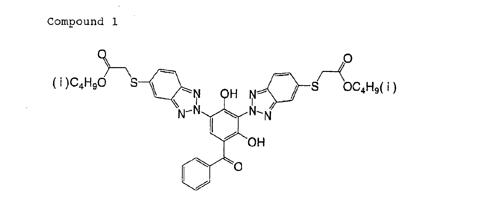
Preferred specific examples of the benzotriazole compound used
in the present invention will be shown below, but the present invention is
not limitcd thereto.
The benzotriazole compound used in the present invention can be
synthesized by methods described or cited in JP-B No. 54-41038, No.
60-14062, No. 2-33709, Japanese Patent No. 2,858,940, No. 2,864468,
British Patcnt No. 1,239,258, U.S. Patent No. 4,587,346, Polymer, vol.
126, p. 1288 (1985), and Monatsh. Chem., vol. 112, p. 1279 (1981), and
analogous methods. Benzotriazole compounds commercially available
as stabilizers for coating compositions and polymers may be used.
The benzotriazole compound may be used singly or may be used
in a combination of two or more kinds thereof. The benzotriazole
compound may be used in combination with another organic compound
as the recording substance. Examples of the organic compound that
can be used in combination include a cyanine organic substance, an
oxonol organic substance, an azo metallic complex, a phthalocyanine
organic substance, a pyrylium organic substance, a thiopyrylium organic
substance, an azurenium organic substance, a squarylium organic
substance, a naphthoquinone organic substance, a triphenylmethane
organic substance and a triallylmethane organic substance.
Substrate of Recording Medium
The medium is constituted with a substrate having thereon a
reflective layer having thereon a recording layer having thereon a sheet
layer. The substrate has a groove depth of (a in Fig. 1) of from 15 to 45
nm, a track pitch (b in Fig. 1) of from 250 to 400 nm, a half-value width of
grooves (c in Fig. 1) of from 60 to 200 nm and a tilt angle (d in Fig. 1) of the
grooves of from 40 to 80°. There are no particular limitations other than
these. Thus, the present invention can be applied to various kinds of
constitutions of optical information recording media. The half-value
width of the grooves (d) herein means a width of the groove at half the
depth of the groove.
Owing to the foregoing constitution, the medium has a recording
capacity and a recording density that are further increased, while basic
performances as a recording medium, such as sensitivity and reflectivity,
are maintained at a high level.
The substrate of the medium can be arbitrarily selected from
various kinds of materials that are used as substrates of conventional
optical information recording media. Examples of the material of the
substrate include glass, polycarbonate, acrylic resin, such as polymethyl
methacrylate, vinyl chloride resin, such as polyvinyl chloride and a vinyl
chloride copolymer, epoxy resin, amorphous polyolefin and polyester,
and these may be used singly or in combination depending on necessity.
These materials can be used in the form of a film or of a plate having
rigidity. Among these materials, use of a polycarbonate resin is
preferred from the standpoint of moisture resistance, dimensional
stability and economy.
In order to increase the recording density, the medium uses a
substrate having grooves with a track pitch of from 250 to 400 nm, which
is smaller than in CD-Rs and DVD-Rs. The track pitch of the substrate
is preferably in a range from 260 to 380 nm, and most preferably in a
range from 280 to 350 nm. If the track pitch is less than 250 nm, a
desired sensitivity (C/N) cannot be obtained, and if it exceeds 400 nm,
high density and large capacity cannot be attained.
In the medium, the half-value width of the groove of the substrate
is in a range from 60 to 200 nm. The half-value width of the grooves of
the substrate is preferably in a range from 80 to 200 nm, and most
preferably in a range from 80 to 150 nm. If the half-value width of the
groove is less than 60 nm or more than 200 nm, the output of the groove
signal will be too small to attain desired tracking.
In the medium, the depth of the grooves of the substrate is in a
range from 15 to 45 nm. The depth of the grooves of the substrate is
preferably in a range from 15 to 40 nm, and most preferably in a range
from 20 to 40 nm. If the depth of the grooves is less than 15 nm, the
tracking signal will be too small to function for desired tracking, due to a
too small phase contrast. If the depth of the grooves exceeds 45 nm on
the other hand, the reflectivity will be small in relation to the phase
contrast, decreasing the sensitivity (C/N), whereby accurate replaying
cannot be carried out.
In the medium, the tilt angle of the grooves of the substrate is in a
range from 40 to 80°. The tilt angle of the grooves is preferably in a
range from 50 to 80°, and most preferably in a range from 60 to 80°. If
the tilt angle of the grooves is less than 40°, the reflectivity will be small in
relation to the phase contrast, decreasing the sensitivity (C/N), whereby
accurate replaying cannot be carried out. If the tilt angle exceeds 80° on
the other hand, the substrate will be difficult to release from a metallic
mold upon molding, and thus defects like clouding will be formed in the
grooves, decreasing the sensitivity (C/N), whereby accurate replaying
cannot be carried out.
The medium preferably satisfies the following inequality in order
to attain high capacity and high density while maintaining performance
as a recording medium.
c + (a/2) × tan(d) < b/2
wherein a (nm) represents the depth, b (nm) represents the track pitch, c
(nm) represents the half-value width, and d (°) represents the tilt angle of
the grooves of the substrate.
An undercoating layer may be formed on the surface of the
substrate on which the reflective layer is to be provided, for such objects
as improvement of flatness, improvement of adhesion strength, and
prevention of degradation of the reflective layer and the recording layer.
Examples of a material of the undercoating layer include a polymer
substance, such as polymethyl methacrylate, an acrylic acid-methacrylic
acid copolymer, a styrene-maleic anhydride copolymer, polyvinyl alcohol,
N-methylolacrylamide, a styrene-vinyltoluene copolymer,
chlorosulfonated polyethylene, cellulose nitrate, polyvinyl chloride,
chlorinated polyolefin, polyester, polyimide, a vinyl acetate-vinyl chloride
copolymer, an ethylene-vinyl acetate copolymer, polyethylene,
polypropylene and polycarbonate, and a surface modifying agent, such as
a silane coupling agent. The undercoating layer of the present invention
can be formed by dissolving or dispersing the foregoing material in a
suitable solvent to prepare a coating composition, and coating the coating
composition onto the surface of the substrate by a coating method such
as a spin coating method, a dip coating method or an extrusion coating
method. The thickness of the undercoating layer is generally in a range
from 0.005 to 20 µm, and more preferably in a range from 0.01 to 10 µm.
Reflective Layer
In the medium, a reflective layer is provided above the substrate
and under the organic substance recording layer, so as to improve the
reflectivity upon replaying of information. A light-reflective substance as
a material of the reflective layer may be any material that exhibits a
reflectivity to laser light of 70% or more, and substances having a high
reflectivity are preferred. Examples thereof include a metal or metalloid,
such as Mg, Se, Y, Ti, Zr, Hf, V, Nb, Ta, Cr, Mo, W, Mn, Re, Fe, Co, Ni, Ru,
Rh, Pd, Ir, Pt, Cu, Ag, Au, Zn, Cd, Al, Ga, In, Si, Gc, Te, Pb, Po, Sn, Bi and
stainless steel.
These materials may be used singly or in combination, or as an
alloy of two or more thereof. Among these, Cr, Ni, Pt, Cu, Ag, Au, Al and
stainless steel are preferred. Metallic Au, metallic Ag, metallic Al and
alloys thereof are particularly preferred, and metallic Ag, metallic Al and
an alloy thereof are most preferred. The reflective layer of the present
invention can be formed by forming the light-reflective material on the
substrate or the recording layer through vapor deposition, sputtering or
ion plating. The thickness of the reflective layer is generally in a range
from 10 to 300 nm, and preferably in a range from 50 to 200 nm.
Formation of Recording Layer
In the medium, the recording layer containing the organic
substance (the aforementioned organic substance constituting the
recording layer) for recording optical information is provided on the
reflective layer.
The formation of the organic substance recording layer can be
carried out by vapor deposition, sputtering, CVD or coating with a solvent,
and coating with a solvent is preferred. The coating temperature may be
from 23 to 50°C without any problem, and is preferably from 24 to 40°C,
and more preferably from 25 to 37°C. In the case where the recording
layer is formed by coating with a solvent, a quencher, a binder and the
like are dissolved, depending on necessity, in the solvent in addition to
the organic substance, such as the phthalocyanine derivative and the
benzotriazole derivative, to prepare a coating composition, and the
coating composition is coated on the surface of the substrate to form a
coated film, which is then dried.
Examples of the solvent for the coating composition include an
ester, such as butyl acetate, ethyl acetate and cellosolve acetate; a ketone,
such as methyl ethyl ketone, cyclohexanone and methyl isobutyl ketone;
a chlorinated hydrocarbon, such as dichloromethane, 1,2-dichloroethane
and chloroform; an amide, such as dimethylformamide; a hydrocarbon,
such as methylcyclohexane; an ether, such as dibutyl ether, diethyl ether,
tetrahydrofuran and dioxane; an alcohol, such as ethanol, n-propanol,
isopropanol, n-butanol and diacetone alcohol; a fluorine solvent, such as
2,2,3,3-tetrafluoropropanol; and a glycol ether, such as ethylene glycol
monomethyl ether, ethylene glycol monoethyl ether, propylene glycol
monomethyl ether. These solvents may be used singly or in a
combination of two or more in consideration of the solubility of the
organic substance used. Various kinds of additives, such as an
antioxidant, a UV absorbent, a plasticizer and a lubricant, may be further
added to the coating composition depending on necessity.
In the case where a binder is used in the organic substance
recording layer, examples of the binder include a natural organic polymer
substance, such as gelatin, a cellulose derivative, dextran, rosin and
rubber; and a synthetic polymer, such as a hydrocarbon resin (e.g.,
polyethylene, polypropylene, polystyrene and polyisobutylene), a vinyl
resin (e.g., polyvinyl chloride, polyvinylidene chloride and a polyvinyl
chloride-polyvinyl acetate copolymer), an acrylic resin (e.g., polymethyl
acrylate and polymethyl methacrylate), polyvinyl alcohol, chlorinated
polyethylene, and an initial condensation product of a thermosetting
resin (e.g., an epoxy resin, a butyral resin, a rubber derivative and a
phenol-formaldehyde resin). In the case where the binder is used as a
material for the recording layer, the usage amount of the binder is
preferably in a range from 0.01 to 50 times by weight, and more
preferably in a range from 0.1 to 5 times by weight, based on the amount
of the organic substance. The concentration of the organic substance in
the coating composition thus produced is generally in a range from 0.01
to 10% by weight, and preferably in a range from 0.1 to 5% by weight.
Examples of the coating method of the organic substance
recording layer include a spraying method, a spin coating method, a
dipping method, a roll coating method, a blade coating method, a doctor
roll method and a screen printing method. The organic substance
recording layer may be a single layer or may have a multilayer structure.
The thickness of the organic substance recording layer is generally in a
range from 20 to 500 nm, preferably in a range from 30 to 300 nm, and
more preferably in a range from 50 to 100 nm.
In the organic substance recording layer of the present invention,
various kinds of discoloration preventing agents may be added for
improvement of the light resistance of the recording layer. As the
discoloration preventing agent, a singlet oxygen quencher is generally
used. As the singlet oxygen quencher, those described in known
publications, such as patent publications, can be utilized. Specific
examples thereof include those described in JP-A No. 58-175693, No.
59-81194, No. 60-18387, No. 60-19586, No. 60-19587, No. 60-35054, No.
60-36190, No. 60-36191, No. 60-44554, No. 60-44555, No. 60-44389, No.
60-44390, No. 60-54892, No. 60-47069, No. 63-209995, No. 4-25492, No.
1-38680, No. 6-26028, German Patent No. 350,399, and
J. of Chem. Soc.
of Japan, Oct. 1992 issue, p. 1141. Preferred examples of the singlet
oxygen quencher include compounds represented by the following
general formula (III).
In the general formula (III), R21 represents an alkyl group, which
may have a substituent, and Q- represents an anion.
In the general formula (III), R21 is generally an alkyl group having
from 1 to 8 carbon atoms, which may have a substituent, and preferably
an unsubstituted alkyl group having from 1 to 6 carbon atoms.
Examples of the substituent on the alkyl group include a halogen atom
(such as F and Cl), an alkoxy group (such as methoxy and ethoxy), an
alkylthio group (such as methylthio and ethylthio), an acyl group (such as
acetyl and propyonyl), an acyloxy group (such as acetoxy and
propyonyloxy), a hydroxyl group, an alkoxycarbonyl group (such as
methoxycarbonyl and ethoxycarbonyl), an alkenyl group (such as vinyl)
and an aryl group (such as phenyl and naphthyl). Among these, a
halogen atom, an alkoxy group, an alkylthio group and an
alkoxycarbonyl group are preferred. Preferred examples of the anion
represented by Q- include ClO4 -, AsF6 -, BF4 - and SbF6 -.
Examples of the compounds represented by the general formula
(III) are shown in Table 2.
| Compound No. | R21 | Q- |
| II-1 | CH3 | ClO4 - |
| II-2 | C2H5 | ClO4 - |
| II-3 | n-C3H7 | ClO4 - |
| II-4 | n-C4H9 | ClO4 - |
| II-5 | n-C5H11 | ClO4 - |
| II-6 | n-C4H9 | SbF6 - |
| II-7 | n-C4H9 | BF4 - |
| II-8 | n-C4H9 | AsF6 - |
The usage amount of the discoloration preventing agent, such as
the singlet oxygen quencher, is generally in a range from 0.1 to 50% by
weight, preferably in a range from 0.5 to 45% by weight, further
preferably in a range from 3 to 40% by weight, and particularly preferably
in a range from 5 to 25% by weight, based on the amount of the organic
substance.
Sheet Layer
In the medium, a sheet layer is provided on the organic substance
recording layer for physically and chemically protecting the recording
layer and the like. The sheet layer may be formed with any material that
has light transmittance, and examples of the material of the sheet layer
used in the present invention include inorganic substances, such as SiO,
SiO2, MgF2, SnO2 and Si3N4, and organic substances, such as a
thermoplastic resin, a thermosetting resin and a UV-curable resin. In
particular, a thermoplastic resin, such as polycarbonate or cellulose
triacetate, is preferred, and a thermoplastic resin exhibiting a moisture
absorbing ratio of 5% or less in an environment with a temperature of
23°C and a relative humidity of 50% is further preferred.
The sheet layer can be formed, for example, by laminating a film
obtained by extrusion molding a plastic onto the reflective layer with an
adhesive. Alternatively, it may be formed by other methods, such as
vacuum deposition, sputtering and coating. In the case of the
thermoplastic resin and the thermosetting resin, the layer may be formed
by dissolving the resin in a suitable solvent to prepare a coating
composition, and the coating composition is coated and dried. In the
case of the UV-curable resin, the UV-curable resin is coated as is or after
dissolving it in a suitable solvent to prepare a coating composition, and is
then irradiated with UV light to achieve curing. In the coating
compositions, various kinds of additives, such as an antistatic agent, an
antioxidant and a UV absorbent, may be added depending on purpose.
The thickness of the sheet layer is generally in a range from 0.1 µm to 1
mm. Through the foregoing process steps, a laminated body for the
medium including the substrate having thereon the reflective layer, the
recording layer and the sheet layer can be produced.
The sheet layer may be provided on the recording layer with an
intermediate layer and an adhesive layer interposed therebetween. The
intermediate layer is provided to improve the storage stability of the
recording layer and to improve the adhesiveness between the recording
layer and the thin film sheet layer. Examples of the material used in the
intermediate layer include an inorganic substance, such as SiO, SiO2,
MgF2, SnO2 and Si3N4. The intermediate layer may be formed by vacuum
deposition, such as vapor deposition or sputtering. In the adhesive layer,
an adhesive containing a photocurable resin is preferably used. For
example, the photocurable resin is coated on the intermediate layer as is
or after dissolving it in a suitable solvent to prepare a coating composition.
A resin film obtained by extrusion molding a plastic is laminated on the
coated layer, and the laminated resin film is irradiated with light to cure
the coated film, whereby the resin film is adhered on the intermediate
layer to form a thin film sheet layer.
Information Recording Method
An information recording method applied to the present invention
is carried out, for example, in the following manner using the optical
information recording medium. The optical information recording
medium is rotated at a constant linear velocity (from 1.2 to 1.4 m/sec for
the CD format) or a constant angular velocity, and irradiated with light
for recording including light at a wavelength of from 380 to 500 nm, such
as semiconductor laser light, from the side of the substrate or from the
side of the protective layer, through a lens having an NA (lens aperture) of
0.7 or more. Upon irradiation, the temperature of the irradiated part of
the organic substance recording layer is increased locally by absorbing
the light, and the temperature is locally increased, and the optical
characteristics of that part are changed by a physical or chemical change
(such as formation of a pit) to attain recording of information.
Examples of the laser light source having an oscillation
wavelength in a range from 380 to 500 nm include a blue semiconductor
laser having an oscillation wavelength in a range from 380 to 500 nm.
The use of the blue semiconductor laser is particularly preferred from the
standpoint of increase of the recording density.
Replaying of the information thus recorded can be carried out by
rotating the optical information recording medium at the same constant
linear velocity and irradiating with laser light from the side of the sheet,
and light thus reflected is detected.
The medium includes, for example, a disk substrate having
pregrooves having a constant track pitch having formed thereon a
reflective layer, a recording layer and a sheet layer laminated in this order.
In the optical information recording medium, a thin film sheet layer is
provided on the side opposite to the substrate, which has a prescribed
thickness (1.2 mm for CD-R), and recording is carried out by irradiation
from the side of the thin film sheet layer, whereby the beam diameter of
the laser light thus irradiated can be narrowed, and thus high density
recording can be carried out with light having a short wavelength of 500
nm or less.
EXAMPLES
The present invention will be described in more detail with
reference to the following Examples, but the present invention is not to be
construed as being limited thereto. In the following description, all
percentages and parts are percentages by weight and parts by weight,
respectively.
EXAMPLE 1
A polycarbonate resin (trade name: PANLITE AD5503 produced by
Teijin Chemicals Ltd.) was subjected to injection molding to produce a
substrate having a thickness of 1.1 mm and a diameter of 120 mm and
having grooves in a spiral form (depth: 100 nm, half-value width: 120 nm,
track pitch: 0.3 µm). On the surface of the substrate on which the
grooves were present, a reflective layer formed with an Ag film having a
thickness of 100 nm was formed by a sputtering method.
2 g of a phthalocyanine organic substance A (ORASOL BLUE GN
produced by Ciba Specialty Chemicals, Co., Ltd.) having maximum
absorption peaks at 340 nm and 680 nm was mixed with 100 ml of
2,2,3,3-tetrafluoropropanol and then dissolved by subjecting to an
ultrasonic treatment for 2 hours to prepare an organic substance coating
composition.
The organic substance coating composition was coated on the Ag
reflective layer by a spin coating method under conditions of 23°C,
50%RH at a rotation number which varied from 300 to 4,000 rpm, and
then maintained at 23°C, 50%RH for 2 hours to form a recording layer
having a thickness of 80 nm.
An ultraviolet ray-curable adhesive (trade name: SD-347
produced by Dainippon Ink And Chemicals, Inc.) was coated on the
organic substance film by a spin coating method at 200 rpm, and a cover
layer formed with a polycarbonate resin sheet (trade name: PUREACE
produced by Teijin Ltd.) having a thickness of 0.07 mm was laminated
thereon. The adhesive was spread over the entire surface by rotating at
a rotation number which varied from 300 to 4,000 rpm, and then
irradiated with ultraviolet rays by using an ultraviolet ray irradiation
lamp, whereby the adhesive was cured to complete adhesion.
An ultraviolet ray-curable adhesive (trade name: SD-347
produced by Dainippon Ink And Chemicals, Inc., solubility in the organic
substance: 0.05%) was further coated on the cover layer by a spin coating
method at 200 rpm. The adhesive was spread over the entire surface by
rotating at a rotation number which varied from 300 to 4,000 rpm, and
then irradiated with ultraviolet rays by using an ultraviolet ray
irradiation lamp, whereby the adhesive was cured to produce a sample.
EXAMPLE 2
A sample was produced in the same manner as in Example 1
except that the organic substance was replaced with a phthalocyanine
organic substance B (SUPER GREEN produced by Ciba Specialty
Chemicals, Co., Ltd.) having maximum absorption peaks at 330 nm and
730 nm.
EXAMPLE 3
A sample was produced in the same manner as in Example 1
except that the organic substance was replaced with a phthalocyanine
organic substance C (FOM0561 produced by Wako Pure Chemical
Industries, Ltd.) having maximum absorption peaks at 340 nm and 680
nm.
COMPARATIVE EXAMPLE 1
A polycarbonate resin (trade name: PANLITE AD5503 produced by
Teijin Chemicals Ltd.) was subjected to injection molding to produce a
substrate having a thickness of 1.1 mm and a diameter of 120 mm and
having grooves in a spiral form (depth: 40 nm, half-value width: 140 nm,
track pitch: 0.3 µm). On the surface of the substrate, on which the
grooves were present, a reflective layer formed with an Ag film having a
thickness of 100 nm was formed by a sputtering method.
On the reflective layer, a lower heat-resistant protective layer
formed with ZnS-SiO2 having a thickness of 170 nm, a recording layer
formed with AgInSbTe having a thickness of 25 nm, and an upper heat-resistant
protective layer formed with ZnS-SiO2 having a thickness of 35
nm were formed in this order by a sputtering method.
An ultraviolet ray-curable adhesive (trade name: SD-347
produced by Dainippon Ink And Chemicals, Inc.) was coated on the upper
heat-resistant protective layer by a spin coating method at 200 rpm, and
a cover layer formed with a polycarbonate resin sheet (trade name:
PUREACE produced by Teijin Ltd.) having a thickness of 0.07 mm was
laminated thereon. The adhesive was spread over the entire surface by
rotating at a rotation number which varied from 300 to 4,000 rpm, and
then irradiated with ultraviolet rays by using an ultraviolet ray
irradiation lamp, whereby the adhesive was cured to complete adhesion.
An ultraviolet ray-curable adhesive (trade name: SD-347
produced by Dainippon Ink And Chemicals, Inc.) was further coated on
the cover layer by a spin coating method at 200 rpm. The adhesive was
spread over the entire surface by rotating at a rotation number which
varied from 300 to 4,000 rpm, and then irradiated with ultraviolet rays by
using an ultraviolet ray irradiation lamp, whereby the adhesive was cured
to produce a sample.
COMPARATIVE EXAMPLE 2
A sample was produced in the same manner as in Comparative
Example 1 except that the recording layer in Comparative Example 1 was
replaced with SbTe.
COMPARATIVE EXAMPLE 3
A sample was produced in the same manner as in Example 1
except that the grooves of the substrate of Example 1 were replaced with
grooves having a depth of 40 nm, a half-value width of 120 nm and a
track pitch of 0.30 µm.
COMPARATIVE EXAMPLE 4
A sample was produced in the same manner as in Example 1
except that the grooves of the substrate of Example 1 were replaced with
grooves having a depth of 160 nm, a half-value width of 120 nm and a
track pitch of 0.30 µm.
COMPARATIVE EXAMPLE 5
A sample was produced in the same manner as in Example 1
except that the organic substance was replaced with an aminobutadiene
organic substance a having a λmax of 360 nm, lower than 400 nm.
The samples of Examples 1 to 3 and Comparative Examples 1 to 5
were evaluated in the following manner.
C/N
The optical disk thus produced was subjected to recording and
replaying by using a recording and replaying evaluation apparatus
(DDU1000 produced by Pulstec Industrial Co., Ltd.) equipped with a 405
nm laser and a pickup of NA 0.85 at a clock frequency of 66 MHz and a
linear velocity of 5.6 m/s, with a single-frequency signal (2T = 0.13 µm),
and the C/N was measured by a spectrum analyzer.
Reproducing durability
The optical disk thus produced was subjected to recording of a
1-7PP modulated signal by using a recording and replaying evaluation
apparatus (DDU1000 produced by Pulstec Industrial Co., Ltd.) equipped
with a 405 nm laser and a pickup of NA 0.85 at a clock frequency of 66
MHz and a linear velocity of 5.6 m/s (laser power: 6 mW). Replaying was
continuously carried out 1,000,000 times in a still mode (laser power: 0.4
mW), and modulation deterioration after 1,000,000 times of replaying
was measured, with an initial modulation degree being evaluated as
100%. Results obtained are shown in Table 3.
| | Recording layer | Depth of grooves | C/N | Reproducing durability |
| Example 1 | Organic substance A | 100 nm | 55 dB (A) | 98% (A) |
| Example 2 | Organic substance B | 100 nm | 51 dB (A) | 99% (A) |
| Example 3 | Organic substance C | 100 nm | 53 dB (A) | 99% (A) |
| Comparative Example 1 | AgInSbTe | 40 nm | 45 dB (A) | 60% (C) |
| Comparative Example 2 | SbTe | 40 nm | 52 dB (A) | 40% (C) |
| Comparative Example 3 | Organic substance A | 40 nm | 40 dB (C) | 98% (A) |
| Comparative Example 4 | Organic substance A | 160 nm | 30 dB (C) | 95% (A) |
| Comparative Example 5 | Organic substance A | 40 nm | 35 dB (C) | 60% (C) |
| Example 24 | Organic substance A | 70 nm | 51 dB (A) | 100% (A) |
It is understood from Table 3 that when an organic substance
having maximum absorption peaks at the particular wavelengths of the
present invention is used in the recording layer, and the depth of the
grooves is in the range of the present invention, both the C/N and the
reproducing durability are excellent, but when the depth of the grooves
deviates from the range of the present invention, the C/N is deteriorated
even if a recording layer containing the particular organic substance is
used. In the case of the samples in which the depth of the grooves was
smaller than 50 nm and the recording layer utilized phase change, the
reproducing durability was considerably deteriorated. Furthermore, in
the case of the sample in which the organic substance having a λmax of
360 nm was used, and the depth of the grooves was smaller than 50 nm,
both the C/N and the reproducing durability were deteriorated.
In the optical recording medium of the present invention, because
the recording layer containing the organic substance having at least one
maximum absorption peak in each of a range from 600 to 800 nm and a
range from 300 to 400 nm is formed on the substrate having the
particular grooves formed thereon, both the C/N and the reproducing
durability are excellent, and high density recording can be carried out
without any problem.
EXAMPLE 4
A polycarbonate resin (trade name: PANLITE AD5503 produced by
Teijin Chemicals Ltd.) was subjected to injection molding to produce a
substrate having a thickness of 0.6 mm and a diameter of 120 mm and
having grooves in a spiral form (depth: 100 nm, half-value width: 120 nm,
track pitch: 0.34 µm) to produce a substrate.
2 g of a phthalocyanine organic substance A (ORASOL BLUE GN
produced by Ciba Specialty Chemicals, Co., Ltd.) having maximum
absorption peaks at 340 nm and 680 nm was mixed with 100 ml of
2,2,3,3-tetrafluoropropanol and then dissolved by subjecting to an
ultrasonic treatment for 2 hours to prepare an organic substance coating
composition.
The organic substance coating composition was coated on the
surface of the substrate, on which the grooves were formed, by a spin
coating method under conditions of 23°C, 50%RH at a rotation number
which varied from 300 to 4,000 rpm, and then maintained at 23°C,
50%RH for 2 hours to form a recording layer having a thickness of 80 nm
in the grooves.
A reflective layer formed with an Ag film having a thickness of 100
nm was formed on the recording layer by a sputtering method.
An ultraviolet ray-curable adhesive (trade name: SD-640
produced by Dainippon Ink And Chemicals, Inc.) was then coated at 40°C
by a spin coating method at 200 rpm, and a polycarbonate resin
substrate having a thickness of 0.6 mm was laminated thereon. The
adhesive was spread over the entire surface by rotating at a rotation
number which varied from 300 to 4,000 rpm, and then cured by
irradiating with ultraviolet rays by using an ultraviolet ray irradiation
lamp to produce a sample.
EXAMPLE 5
A sample was produced in the same manner as in Example 4
except that the organic substance was replaced with a phthalocyanine
organic substance B (SUPER GREEN produced by Ciba Specialty
Chemicals, Co., Ltd.) having maximum absorption peaks at 330 nm and
730 nm.
EXAMPLE 6
A sample was produced in the same manner as in Example 4
except that the organic substance was replaced with a phthalocyanine
organic substance C (FOM0561 produced by Wako Pure Chemical
Industries, Ltd.) having maximum absorption peaks at 340 nm and 680
nm.
COMPARATIVE EXAMPLE 6
A polycarbonate resin (trade name: PANLITE AD5503 produced by
Teijin Chemicals Ltd.) was subjected to injection molding to produce a
substrate having a thickness of 0.6 mm and a diameter of 120 mm and
having grooves in a spiral form (depth: 40 nm, half-value width: 120 nm,
track pitch: 0.34 µm). On the surface of the substrate, on which the
grooves were present, a lower heat-resistant protective layer formed with
ZnS-SiO2 having a thickness of 170 nm, a recording layer formed with
AgInSbTe having a thickness of 25 nm, an upper heat-resistant
protective layer formed with ZnS-SiO2 having a thickness of 35 nm, and a
reflective layer formed with an Ag film having a thickness of 100 nm were
formed by a sputtering method.
An ultraviolet ray-curable adhesive (trade name: SD-640
produced by Dainippon Ink And Chemicals, Inc.) was coated on the
reflective layer at 40°C by a spin coating method at 200 rpm, and a
polycarbonate resin substrate having a thickness of 0.6 mm was
laminated thereon. The adhesive was spread over the entire surface by
rotating at a rotation number which varied from 300 to 4,000 rpm, and
then cured by irradiating with ultraviolet rays by using an ultraviolet ray
irradiation lamp to complete adhesion.
COMPARATIVE EXAMPLE 7
A sample was produced in the same manner as in Comparative
Example 6 except that the recording layer in Comparative Example 6 was
replaced with SbTe.
COMPARATIVE EXAMPLE 8
A sample was produced in the same manner as in Example 4
except that the grooves of the substrate of Example 4 were replaced with
grooves having a depth of 40 nm, a half-value width of 120 nm and a
track pitch of 0.34 µm.
COMPARATIVE EXAMPLE 9
A sample was produced in the same manner as in Example 4
except that the grooves of the substrate of Example 4 were replaced with
grooves having a depth of 160 nm, a half-value width of 120 nm and a
track pitch of 0.34 µm.
COMPARATIVE EXAMPLE 10
A sample was produced in the same manner as in Example 4
except that the organic substance was replaced with an aminobutadiene
organic substance a having a λmax of 360 nm, lower than 400 nm.
The samples of Examples 4 to 6 and Comparative Examples 6 to
10 were evaluated in the following manner.
C/N
The optical disk thus produced was subjected to recording (laser
power: 1.0 mW) and replaying (laser power: 0.6 mW) by using a recording
and replaying evaluation apparatus (DDU1000 produced by Pulstec
Industrial Co., Ltd.) equipped with a 405 nm laser and a pickup of NA
0.65 at a clock frequency of 20 MHz and a linear velocity of 2.0 m/s, with
a single-frequency signal (3T = 0.29 µm), and the C/N was measured by a
spectrum analyzer.
Reproducing durability
The optical disk thus produced was subjected to recording of an
EMF modulated signal by using a recording and replaying evaluation
apparatus (DDU1000 produced by Pulstec Industrial Co., Ltd.) equipped
with a 405 nm laser and a pickup of NA 0.65 at a clock frequency of 20
MHz and a linear velocity of 2.0 m/s (laser power: 1.0 mW). Replaying
was carried out in a still mode (laser power: 0.6 mW), and modulation
deterioration after 1,000,000 times of continuous replaying was
measured, with an initial modulation degree being evaluated as 100%.
Results obtained are shown in Table 4.
| | Recording layer | Depth of grooves | C/N | Reproducing durability |
| Example 4 | Organic substance A | 100 nm | 55 dB (A) | 100% (A) |
| Example 5 | Organic substance B | 100 nm | 51 dB (A) | 99% (A) |
| Example 6 | Organic substance C | 100 nm | 53 dB (A) | 99% (A) |
| Comparative Comparative Example 6 | AgInSbTe | 40 nm | 49 dB (A) | 40% (C) |
| Comparative Comparative Example 7 | GeSbTe | 40 nm | 45 dB (B) | 45% (C) |
| Comparative Example 8 | Organic substance A | 40 nm | 35 dB (C) | 98% (A) |
| Comparative Example 9 | Organic substance A | 160 nm | 30 dB (C) | 95% (A) |
| Comparative Comparative Example 10 | Organic substance A | 40 nm | 35 dB (C) | 50% (C) |
It is understood from Table 4 that when an organic substance
having maximum absorption peaks at the particular wavelengths of the
present invention is used in the recording layer, and the depth of the
grooves is in the range of the present invention, both the C/N and the
reproducing durability are excellent, but when the depth of the grooves
deviates from the range of the present invention, the C/N is deteriorated
even if a recording layer containing the particular organic substance is
used. In the case of the samples, in which the depth of the grooves was
smaller than 50 nm, and the recording layer utilized phase change, the
reproducing durability was considerably deteriorated. Furthermore, in
the case of the sample in which the organic substance having a λmax of
360 nm was used, and the depth of the grooves was smaller than 50 nm,
both the C/N and the reproducing durability were deteriorated.
In the optical recording medium of the present invention, because
the recording layer containing the organic substance having at least one
maximum absorption peak in each of a range from 600 to 800 nm and a
range from 300 to 400 nm is formed on the substrate having the
particular grooves formed thereon, both the C/N and the reproducing
durability are excellent, and high density recording can be carried out
without any problem.
AT Examples of Phthalocyanine Organic Substance Recording Layer
Examples 7 to 11 and 15 to 18, and Comparative Examples 11, 12,
15 and 16
A substrate formed with a polycarbonate resin (trade name:
PANLITE AD5503 produced by Teijin Chemicals Ltd.) by injection
molding having a thickness of 1.2 mm and a diameter of 120 mm and
having grooves in a spiral form (with depth, track pitch, half-value width
and tilt angle as shown in Table 5) was prepared. On the surface of the
substrate on which the grooves were present, a reflective layer having a
thickness of 100 nm was formed by sputtering Ag. Separately, a
phthalocyanine produced by Ciba Specialty Chemicals, Co., Ltd.
(ORASOL BLUE GN) was mixed with 2,2,3,3-tetrafluoropropanol and
then dissolved by applying ultrasonic waves for 2 hours to obtain a
coating composition for forming a recording layer (concentration: 2% by
weight). The organic compound coating composition was coated by a
spin coating method under conditions of 23°C, 50%RH at a rotation
number which varied from 300 to 4,000 rpm. Thereafter, after storing at
23°C, 50%RH for 1 hour, ZnS-SiO2 was sputtered to make a thickness of
5 nm. A UV-curable adhesive (SD-640 produced by Dainippon Ink And
Chemicals, Inc.) was coated by a spin coating method at a rotation
number which varied from 100 to 300 rpm, and a polycarbonate sheet
(PUREACE produced by Teijin Ltd., thickness: 70 µm) was laminated
thereon. The adhesive was spread over the entire surface by rotating at
a rotation number which varied from 300 to 4,000 rpm, and then
irradiated with ultraviolet rays by using a UV irradiation lamp, whereby
the adhesive was cured to produce samples of optical information
recording media (optical disks) of Examples 7 to 11 and 15 to 18
according to the present invention and Comparative Examples 11, 12, 15
and 16.
B: Examples of Benzotriazole Organic Substance Recording Layer
Examples 12 to 14 and 19 to 23, and Comparative Examples 13,
14, 17 and 18
A substrate formed with a polycarbonate resin (trade name:
PANLITE AD5503 produced by Teijin Chemicals Ltd.) by injection
molding having a thickness of 1.2 mm and a diameter of 120 mm and
having grooves in a spiral form (with depth, track pitch, half-value width
and tilt angle as shown in Table 5) was prepared. On the surface of the
substrate on which the grooves were prcsent, a reflective layer having a
thickness of 100 nm was formed by sputtering Ag. Separately, the
following Compound 1 (benzotriazole) was mixed with
2,2,3,3-tetrafluoropropanol and then dissolved by applying ultrasonic
waves for 2 hours to obtain a coating composition for forming a recording
layer (concentration: 2% by weight). The organic compound coating
composition was coated by a spin coating method under conditions of
23°C, 50%RH at a rotation number which varied from 300 to 4,000 rpm.
Thereafter, after storing at 23°C, 50%RH for 1 hour, ZnS-SiO
2 was
sputtered to make a thickness of 5 nm. A UV-curable adhesive (SD-640
produced by Dainippon Ink And Chemicals, Inc.) was coated by a spin
coating method at a rotation number which varied from 100 to 300 rpm,
and a polycarbonate sheet (PUREACE produced by Teijin Ltd., thickness:
70 µm) was laminated thereon. The adhesive was spread over the entire
surface by rotating at a rotation number which varied from 300 to 4,000
rpm, and then irradiated with ultraviolet rays by using a UV irradiation
lamp, whereby the adhesive was cured to produce samples of optical
information recording media (optical disks) of Examples 12 to 14 and 19
to 23 according to the present invention and Comparative Examples 13,
14, 17 and 18.
The optical information recording media (optical disks) thus
prepared were subjected to recording with a 3T-EFM signal by using a
blue semiconductor laser having an oscillation wavelength of 405 nm at a
linear velocity of 3.5 m/sec through a lens system having an aperture
(NA) of 0.85, and then the recorded signal was replayed. The reflectivity
of non-recorded grooves was measured by using "DDU1000" produced by
Pulstec Industrial Co., Ltd. equipped with a 405 nm blue semiconductor
laser and a lens system of an aperture (NA) of 0.85. A 3T signal was
recorded at 8 mW, and the sensitivity (C/N) thereof was measured. The
evaluation results are shown in Table 5.
| | Organic substance | Depth of grooves (nm) | Track pitch (nm) | Half-value width of grooves (nm) | Tilt angle of grooves (°) | Reflectivity of non-recorded grooves (%) | C/N |
| Comparative Example 11 | D | 10 | 300 | 100 | 70 | 31 | 33 |
| Example 7 | D | 15 | 300 | 100 | 70 | 61 | 53 |
| Example 8 | D | 20 | 300 | 100 | 70 | 70 | 54 |
| Example 9 | D | 30 | 300 | 100 | 70 | 65 | 56 |
| Example 10 | D | 40 | 300 | 100 | 70 | 64 | 55 |
| Example 11 | D | 45 | 300 | 100 | 70 | 59 | 51 |
| Comparative Example 12 | D | 50 | 300 | 100 | 70 | 29 | 36 |
| Comparative Example 13 | E | 30 | 240 | 100 | 70 | 26 | 36 |
| Example 12 | E | 30 | 250 | 100 | 70 | 57 | 58 |
| Example 13 | E | 30 | 300 | 100 | 70 | 59 | 60 |
| Example 14 | E | 30 | 400 | 100 | 70 | 55 | 56 |
| Comparative Example 14 | E | 30 | 410 | 100 | 70 | 25 | 36 |
| Comparative Example 15 | D | 30 | 300 | 50 | 70 | 38 | 35 |
| Example 15 | D | 30 | 300 | 60 | 70 | 53 | 50 |
| Example 16 | D | 30 | 300 | 80 | 70 | 61 | 52 |
| Example 17 | D | 30 | 300 | 150 | 70 | 64 | 54 |
| Example 18 | D | 30 | 300 | 200 | 70 | 64 | 51 |
| Comparative Example 16 | D | 30 | 300 | 220 | 70 | 15 | 34 |
| Comparative Example 17 | E | 30 | 300 | 80 | 35 | 16 | 37 |
| Example 19 | E | 30 | 300 | 80 | 40 | 50 | 53 |
| Example 20 | E | 30 | 300 | 80 | 50 | 53 | 54 |
| Example 21 | E | 30 | 300 | 80 | 60 | 56 | 58 |
| Example 22 | E | 30 | 300 | 80 | 70 | 58 | 59 |
| Example 23 | E | 30 | 300 | 80 | 80 | 51 | 52 |
| Comparative Example 18 | E | 30 | 300 | 80 | 85 | 33 | 33 |
Note: D: Phthalocyanine organic substance
E: Benzotriazole organic substance |
It was found from the results in Table 5 that the optical disks
according to the present invention (Examples 7 to 23) exhibited a high
reflectivity to laser light having a wavelength of 405 nm condensed by
passing through a lens having an aperture (NA) of 0.85 and had a high
sensitivity in comparison to the optical disks of Comparative Examples
11 to 18. Therefore, it is understood that by using the optical
information recording medium according to the present invention, an
optical disk can be obtained that has high recording characteristics to
short wavelength laser light having a wavelength of from 380 to 500 nm
passing through a lens having an aperture (NA) of 0.7 or more.
The medium has a recording layer containing an organic
substance and grooves having a depth of from 15 to 45 nm, a track pitch
of from 250 to 400 nm, a half-value width of from 60 to 200 nm and a tilt
angle of from 40 to 80°, and thus exhibits effects such that high density
recording and replaying of information can be carried out by irradiating
with short wavelength laser light having a wavelength of from 380 to 500
nm, and good recording and replaying characteristics, such as high
sensitivity and high reflectivity, are exhibited. Therefore, recording of
information can be carried out at a higher density than the conventional
CD-R and DVD-R, and information in a larger capacity can be recorded.