EP1253566A2 - Fire detector unit - Google Patents
Fire detector unit Download PDFInfo
- Publication number
- EP1253566A2 EP1253566A2 EP02000988A EP02000988A EP1253566A2 EP 1253566 A2 EP1253566 A2 EP 1253566A2 EP 02000988 A EP02000988 A EP 02000988A EP 02000988 A EP02000988 A EP 02000988A EP 1253566 A2 EP1253566 A2 EP 1253566A2
- Authority
- EP
- European Patent Office
- Prior art keywords
- light
- base
- fire detector
- collector
- set forth
- Prior art date
- Legal status (The legal status is an assumption and is not a legal conclusion. Google has not performed a legal analysis and makes no representation as to the accuracy of the status listed.)
- Granted
Links
Images







Classifications
-
- G—PHYSICS
- G08—SIGNALLING
- G08B—SIGNALLING SYSTEMS, e.g. PERSONAL CALLING SYSTEMS; ORDER TELEGRAPHS; ALARM SYSTEMS
- G08B17/00—Fire alarms; Alarms responsive to explosion
- G08B17/06—Electric actuation of the alarm, e.g. using a thermally-operated switch
-
- G—PHYSICS
- G08—SIGNALLING
- G08B—SIGNALLING SYSTEMS, e.g. PERSONAL CALLING SYSTEMS; ORDER TELEGRAPHS; ALARM SYSTEMS
- G08B17/00—Fire alarms; Alarms responsive to explosion
- G08B17/10—Actuation by presence of smoke or gases, e.g. automatic alarm devices for analysing flowing fluid materials by the use of optical means
- G08B17/103—Actuation by presence of smoke or gases, e.g. automatic alarm devices for analysing flowing fluid materials by the use of optical means using a light emitting and receiving device
- G08B17/107—Actuation by presence of smoke or gases, e.g. automatic alarm devices for analysing flowing fluid materials by the use of optical means using a light emitting and receiving device for detecting light-scattering due to smoke
-
- G—PHYSICS
- G08—SIGNALLING
- G08B—SIGNALLING SYSTEMS, e.g. PERSONAL CALLING SYSTEMS; ORDER TELEGRAPHS; ALARM SYSTEMS
- G08B17/00—Fire alarms; Alarms responsive to explosion
- G08B17/10—Actuation by presence of smoke or gases, e.g. automatic alarm devices for analysing flowing fluid materials by the use of optical means
- G08B17/11—Actuation by presence of smoke or gases, e.g. automatic alarm devices for analysing flowing fluid materials by the use of optical means using an ionisation chamber for detecting smoke or gas
- G08B17/113—Constructional details
-
- G—PHYSICS
- G08—SIGNALLING
- G08B—SIGNALLING SYSTEMS, e.g. PERSONAL CALLING SYSTEMS; ORDER TELEGRAPHS; ALARM SYSTEMS
- G08B29/00—Checking or monitoring of signalling or alarm systems; Prevention or correction of operating errors, e.g. preventing unauthorised operation
- G08B29/18—Prevention or correction of operating errors
- G08B29/183—Single detectors using dual technologies
Definitions
- the present invention is directed to a fire detector unit, and more particularly to a fire detector unit of a scattering light detection type.
- Fire detector units of a scattering light detection type have been widely utilized to monitor a smoke density which is proportional to an amount of light scattering due to the presence of smoke particles, and to determine the fire presence by comparing the smoke density with a predetermined threshold.
- Japanese Utility Model Publication No. 4-108293 discloses one typical fire detector unit which includes a base with a smoke chamber, a light emitting diode directing an incident light into the smoke chamber, and a photo diode collecting a light scattering due to the smoke particles in the smoke chamber to generate an electric signal indicative of the amount of the light received.
- the electric signal is processed at a fire detecting circuit which provides a fire warning signal when the detected smoke density becomes critical.
- the detector unit includes a circuit board which is secured to the base and mounts the light emitting diode, the photo diode, and electronic components forming the fire detecting circuit.
- the detector unit is provided with a metal-made shield which is formed separately from the base and is assembled together with the circuit board on the base. Since the shield is formed separately from the base, an extra work is required to apply the shield to the circuit board and fix the shield to the base, in addition to mounting the circuit board to the base, when assembling the detector unit, thereby lowering manufacturing efficiency. Therefore, it is not easy to assemble the detector unit at a low manufacturing cost with the use of an automatic fabrication technique.
- the fire detector unit in accordance with the present invention includes a base made of a molded plastic to have a labyrinth wall which projects on the circumference of the base to define therein a smoke chamber.
- the labyrinth wall permits an entry of smoke particles but prohibits the entry of an ambient light into the smoke chamber.
- the base carries a light projector which directs an incident light from a light emitting element into the smoke chamber.
- the base also carries a light collector which collects a light scattered by the smoke particles in the smoke chamber to a light receiving element.
- the light receiving element generates an electric signal indicative of the amount of the light received.
- a fire detecting circuit is connected to receive the electric signal so as to provide a fire warning signal based upon the electric signal.
- the light emitting element, the light receiving element, and the electronic components forming the fire detecting circuit are mounted on a circuit board which is assembled on the base. Included in the detector unit is a metal-made electromagnetic shield which protects the light receiving element from electromagnetic radiation noises.
- the characterizing feature of the present invention resides in that the electromagnetic shield is integrally molded into the base and has a ground terminal for connection with a ground line of the circuit board, and that the circuit board is fixed to the base by means of metal-made terminal pins which are also integrally molded in the base for electrical connection with the fire detecting circuit and which project through the circuit board for connection with an external line.
- the electrical connection of the shield to the electric circuitry as well as the connection of the circuit board to the base can be made simultaneously simply by mounting the circuit board to the base, thereby facilitating the assembly of the detector unit.
- the labyrinth wall is molded together with the base to form a unitary structure in which the electromagnetic shield is embedded, thereby reducing the number of the parts for easy assembly of the detector unit.
- the electromagnetic shield and the terminal pins are prepared from a single metal sheet by striking the metal sheet and bending the struck portions thereof, which also makes it easy to fabricate the detector unit.
- the detector unit may further include an insect deterring cover which is molded from a plastic material to have a side wall and a bottom wall.
- the side wall is in the form of a screen which surrounds the labyrinth wall so as to prevent flying insects or the like foreign matters from entering the smoke chamber, and has a number of air vents permitting the entry of the smoke particles into the smoke chamber through the labyrinth wall.
- the bottom wall is provided for covering an open bottom of the base to close the smoke chamber. Formed on the interior surface of the bottom wall are first and second masks which make the light projector intact from a light not coming directly from the light emitting element and make the light collector intact from a scattered light not due to the presence of the smoke particles.
- the side wall of the insect deterring cover is formed with at least one blind section devoid of the air vents.
- the blind section extends over a limited circumference of the labyrinth wall in an immediately opposed relation to one of the light projector and the light collector.
- the air vents on opposite of the blind section are so oriented as to direct the ambient air towards the labyrinth wall along a direction generally parallel to a line connecting the blind section to a geometric center of the base.
- the air on opposite of the blind section can be guided smoothly into the smoke chamber to compensate for deficiency of the air flow that is prevented from entering the smoke chamber by the presence of the blind section, which is necessary for avoiding any inadmissible light leak through around the light protector and the light collector.
- the labyrinth wall includes a plurality of L-shaped studs each having an outside corner and an inside corner.
- the L-shaped studs are arranged circumferentially around the base in such a manner that the outside corner of the L-shaped stud projects into the inside corner of the adjacent L-shaped stud.
- Two of the L-shaped studs disposed forwardly of the light collector along an optical axis of the light collector are joined at the outside corners to form thereat a combined stud of a generally X-shaped configuration.
- the X-shaped combined stud is found advantageous to the entry of the ambient light into the field of view of the light collector, while minimizing the loss of the air flow into the smoke chamber.
- the X-shaped combined stud is formed with a V-shaped recess which opposes to the light collector with respect to the optical axis thereof and constitutes a light trap responsible for preventing the incident light from reflecting towards the light collector.
- the light trap in the form of the V-shaped recess is defined by a pair of first and second legs each being a part of the combined stud with the first leg located closer towards the light projector than the second leg.
- the light trap also includes a shield ledge which projects from the first leg and a concave at the bottom of the recess. The concave is hidden behind the shield ledge from the light projector.
- the light trap may be further provided with a reflecting section in the form of a serration which is opposed to the light collector and is configured to reflect the incident light deep into the V-shaped recess away from the light collector.
- the base is preferred to include a shielding post which projects at a location between the light trap and the light projector in a spaced relation respectively therefrom for interruption of the light from the light projector towards the light trap.
- the shielding post is also located outside of an incident angle of the light collector.
- the light emitting element and the light receiving element are mounted on the circuit board so that, when the circuit board is secured to the base, the individual optical axes of these elements extend generally perpendicular to a plane of the base.
- the light projector has a light projecting axis which extends within the smoke chamber in parallel with the plane of the base
- the light collector has a light collecting axis which extends within the smoke chamber in parallel with the plane of the base in a crossing relation with the light projecting axis.
- the light projector forms a first light guide which changes the direction of the light beam from the light emitting element to direct it along the light projecting axis.
- the light collector forms a second light guide which changes the direction of the light collected along the collecting optical axis to direct it along the optical axis of the light receiving element.
- a light emitting diode (LED) utilized as the light emitting element can be mounted upright on the circuit board without being accompanied with an otherwise necessary awkward work of bending the leads of LED. Further, the upright mounting of LED can minimize the length of the leads and therefore an overall height dimension of the assembly of the base and the circuit board, contributing to give a low-profile structure of the detector unit.
- LED light emitting diode
- the light projector and the light collector are each in the form of an optical prism.
- the optical prism defining the light collector may includes an integrally formed converging lens which converges the collected light towards the light receiving element for improving detecting efficiency.
- the fire detector unit is a combination detector for detecting an environment temperature and a smoke density in the environment, and is utilized to determine a fire presence based upon the detected temperature and the smoke density.
- the smoke density is obtained as proportional to an amount of scattering light due to the presence of smoke particles.
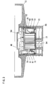
- the fire detector unit includes a support 10 which is adapted to be installed on a ceiling or the like structure of a room.
- the support 10 holds an optical base 20 which accommodates various optical and electronic components, an insect deterring cover 70, and a guard 90.
- the base 20 is molded from a plastic material into a cylindrical shape having a closed top and an open bottom.
- the insect deterring cover 70 is also molded from a plastic material into a cylindrical shape with an open top and a closed bottom.
- the cover 70 is fitted over the base 20 to define therebetween a smoke chamber 24 for detection of the smoke density of the air introduced in the chamber.
- the guard 90 is also made of a molded plastic to fit over the cover 70 and is hooked at its top end to a periphery of a center recess 11 of the support 10, as shown in FIG. 3. Thus, the base 20 and the cover 70 are retained within the guard 90 and are secured to support 10.
- the base 20 has a top wall 21 with a brim 22 upstanding from the periphery of the top wall.
- a circuit board 50 which mounts the electronic components which include a light emitting element (e.g. LED) 51, a light receiving element (e.g. a photo-diode) 52, a thermistor 54, and the other components forming a fire detecting circuit.
- the LED 51 and the photo diode 52 are mounted on the circuit board 50 with the individual optical axes extending perpendicular to the plane of the circuit board 50 and therefore to the plane of the top wall 21 of the base 20.
- the thermistor 54 projects outwardly through the smoke chamber 24 and the bottoms of the cover 70 for sensing the ambient temperature.
- the circuit board 50 is secured to the top wall 21.
- the base 20 also carries a light projector 61 in the form of a prism and a light collector 62 in the form of a combination prism and convex lens which are cooperative with the LED 51 and the photo-diode 52 to constitute an optical system for detection of the smoke density with regard to the air introduced into the smoke chamber 24.
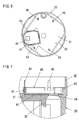
- the base 20 has a labyrinth wall 30 which is a side wall surrounding the smoke chamber 24 and permits the entry of the ambient air but prohibits the entry of the ambient light into the smoke chamber 24. As shown in FIG. 5, the labyrinth wall 30 is defined by a plurality of L-shaped studs 33, and holders 31 and 32 for the light projector 61 and the light collector 62, respectively.
- the L-shaped studs 33 are arranged together with the holders along a circumference of the base 20 in such a manner that an outside corner of the stud 33 projects into an inside corner of the adjacent stud or a concave of the adjacent holder and a convex of the each holder projects into an inside corner of the adjacent stud 31, thereby forming a bent channel between the two adjacent ones of the studs and the holders for introducing the ambient air into the smoke chamber 24, as indicated by an arrowed line in FIG. 5.
- the cover 70 is formed on its bottom wall 73 with first and second retainers 71 and 72 respectively for retaining the light projector 61 and the light collector 62 in correct positions with tabs 64 and 65 of the light projector 61 and the light collector 62 being inserted into corresponding slits 74 and 75 of the retainers.
- the light projector 51 is set to orient its light projecting axis PX extending within the smoke chamber 24 in parallel with the top wall 21 of the base 20, while the light collector 62 is set to orient its light collecting axis CX extending within the smoke chamber in parallel with the top wall 21 of the base in a crossing relation with the light projecting axis PX at an angle of about 100 degrees, as shown in FIG. 5.
- the light projector 61 in the form of the prism has a function of changing the direction of the light beam from the LED 51 to direct it along the light projecting axis (PX).
- the light collector 62 also in the form of the prism has a function of changing the direction of the light collected along the light collecting axis (CX) to direct it along the optical axis of the photo-diode 52.
- the scattering light due to the presence of the smoke particles can be collected by the photo-diode 62 so as to give the smoke density proportional to the amount of the smoke particles within the smoke chamber.
- the collected light can be successfully received at the photo-diode 52 to enhance the output thereof for reliable smoke density detection.
- the photo-diode 52 can generally produce only a minute output on the order of pA for indication of a critical smoke density even under the condition that the LED 61 produces a light output on the order of mW.
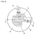
- the labyrinth wall 30 includes a light trap 34 at a portion diametrically opposed to the light collector 62, i.e., forwardly thereof along the light colleting axis (CX) in order to prevent a stray light from entering the light collector 62.
- the light trap 34 is in the form of an X-shaped combined stud in which the two adjacent L-shaped studs 33 join at their outside corners, and gives a V-shaped recess facing the light collector 62.
- the V-shaped recess is defined by first and second legs 35 and 36 each being a part of the combined stud and is formed at its bottom with a narrow concave 37 having a reduced angle of aperture.
- the first leg 35 which is closer to the light projector 61 than the second leg 36, is formed with a shield ledge 38 projecting in a direction of concealing the concave 37 therebehind from the light projector 61. While the second leg 36 is formed on its surface opposing the first leg with a serration 39 which reflects the incident light deep into the V-shaped recess away from the light collector 62.
- a serration 39 which reflects the incident light deep into the V-shaped recess away from the light collector 62.
- a shielding post 26 is formed halfway between the light projector 61 and the light trap 34 to keep the light trap intact from the direct beam from the light projector.
- the shielding post 26 is also located outside of an incident angle of the light collector 62 so as not to reflect the light towards the light collector.
- a tubular jacket 28 is formed halfway between the light projector 61 and the light collector 62 in order to pass through the thermistor 54.
- a metal-made electromagnetic shield 40 is integrated into the top wall 21 of the base 20 as a result of being embedded when molding the base 20, in order to give an electromagnetic protection over a portion of the circuit board 50, particularly the photo-diode 52 and the associated circuit which is susceptible to external electromagnetic waves or noises.
- the shield 40 is of a generally shallow configuration with an embedded flat bottom 41 and side rims 42 bent upward from the edges of the bottom 41 to surround the portion of the circuit board. Two of the side rims 42 is integrally formed respectively with ground terminals 43 which extend through the circuit board 50 for electrical connection with a ground line of the circuit board as well as for physical connection to the board by soldering.
- the bottom 41 of the shield 40 has a window 44 through which the photo-detector 52 communicates with the light collector 62.
- the base 20 carries molded-in terminal pins 46 which project from within the top wall 21 for soldering connection with the fire detection circuit on the board 50 positioned on the top wall 21, thereby physically securing the circuit board 50 to the base in cooperation with the ground terminals 43.
- the terminal pins 46 project through the circuit board 50 so as to be used for electrical connection with an external line in order to transmit the fire warning signal generated at the fire detection circuit to be indicative of the fire presence when the detected parameters become critical.
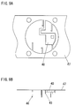
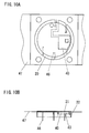
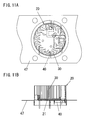
- the electromagnetic shield 40 and the terminal pins 46 are struck from a single metal sheet 47. Portions that are subsequently bent upward to form the side rims 42, ground terminals 43, and the terminal pins 46 are indicated by hatched lines in the figure. After these portions are bent as shown in FIGS. 9A and 9B, the metal sheet 47 is set in a molding die where the upper fraction of the base 20 is molded with the shield 40 and the terminal pins 46 being partially embedded in the upper fraction of the base 20, as shown in FIGS. 10A and 10B. Subsequently, the remaining fraction of the base 20 is molded integrally on the upper fraction thereof to complete the base 20 including the labyrinth wall 30, as shown in FIGS. 11A and 11B. Thereafter, the metal sheet 47 is cut out from thus molded base 20. In this sense, the base 20 is molded into a unitary structure including the labyrinth wall 20, the shield 40, and the terminal pins 46.
- the insect deterring cover 70 is formed in its bottom wall 73 with an aperture 77 through which the thermistor 54 extends in such a manner as to prevent the entry of inadmissible lights into the smoke chamber 24.
- the retainers 71 and 72 projecting on the bottom wall 73 are configured to function as individual masks which prevent the inadmissible light from going towards the light projector 61 and the light collector 62, thereby protecting the light projector 61 intact from undesired light beams which would otherwise cause the light projector to direct a false light beam towards the light collector, and also protecting the light collector 62 intact from undesired light beams which would otherwise received at the light collector and cause an erroneous smoke density detection.
- the bottom wall 73 is formed with a series of notches 78 which are so configured as not to reflect the stray light not due to the smoke particles towards the light collector 62.
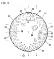
- a side wall 81 of the cover 70 Formed in a side wall 81 of the cover 70 are a number of air vents 82 which permit the entry of the ambient air into the smoke chamber 24 through the labyrinth wall 30 of the base 20.
- the side wall 81 includes blind sections 83 which are circumferentially spaced to conceal therebehind the light projector 61, the light collector 62, and the portions of the labyrinth wall diametrically opposite to the light projector and the light collector in order to eliminate the entry of the inadmissible light into the smoke chamber.
- the air vents 82 on opposite of each blind section 83 are so oriented as to direct the ambient air towards the labyrinth wall 30 along a direction generally parallel to a line connecting the blind section to a geometric center of the base, as indicated by arrowed lines in FIG. 16.
- the orientation of the air vents 82 is determined by separate outer molding dies which are used to fabricate the cover 70. That is, four outer molding dies are used in combination of a core die to surround the entire circumference of the cover 70.
- Each of the four outer molding dies which are separated in mutually perpendicular directions as indicated by arrowed lines in FIG. 17, is configured to leave the blind section 83 in the middle of the circumferential length of the die and to leave the air vents 82 uniformly oriented in the separating direction such that the air vents 82 on opposite of the blind section 83 are oriented in the direction generally parallel to the line connecting the blind section 83 and the geometrical center of the cover 70.
- the fire detecting circuit realized by the circuit board 50 includes a light generating and receiving section 100, a microcomputer 110 responsible for determining the fire presence to generate the fire warning signal, and a transmitter 120 which transmits the fire warning signal through the external line to a fire supervising station.
- the section 100 includes a current controller 101 for controlling a current being fed to the LED 51 for a controlled light output therefrom, a current-voltage (I/V) converter 102 for converting the current output of the photo-diode 52 into a corresponding output voltage.
- I/V current-voltage
- the output voltage is amplified at a gain selector 103 at a suitable amplification factor and is regulated to a suitable voltage level at a gain adjuster 104 followed by being processed at an offset adjuster 105 to provide an analogue signal indicative of the detected smoke density.
- a sensitivity controller 106 is provided for adjustment of the gain amplification factor at the gain selector 103 as well as for adjustment of the current being supplied to the LED 51.
- the analog output is converted into a digital value in the microcomputer 110 which issues the fire warning signal when the detected smoke density alone or in combination with the detected temperature satisfies a predetermined criteria.
Landscapes
- Business, Economics & Management (AREA)
- Emergency Management (AREA)
- Physics & Mathematics (AREA)
- General Physics & Mathematics (AREA)
- Chemical & Material Sciences (AREA)
- Analytical Chemistry (AREA)
- Fire-Detection Mechanisms (AREA)
Abstract
Description
- 10
- support
- 11
- center recess
- 20
- optical base
- 21
- top wall
- 22
- brim
- 24
- smoke chamber
- 26
- shielding post
- 28
- tubular jacket
- 30
- labyrinth wall
- 31
- holder
- 32
- holder
- 33
- L-shaped stud
- 34
- light trap
- 35
- first leg
- 36
- second leg
- 37
- concave
- 38
- shield ledge
- 29
- serration
- 40
- electromagnetic shield
- 41
- bottom
- 42
- side rim
- 43
- ground terminal
- 44
- window
- 46
- terminal pin
- 47
- metal sheet
- 50
- circuit board
- 51
- LED
- 52
- photo-diode
- 54
- thermistor
- 61
- light projector
- 62
- light collector
- 64
- tab
- 65
- tab
- 70
- insect deterring cover
- 71
- retainer
- 72
- retainer
- 73
- bottom wall
- 74
- slit
- 75
- slit
- 77
- aperture
- 78
- notch
- 81
- side wall
- 82
- air vent
- 83
- blind section
- 90
- guard
- 100
- light generating and receiving section
- 101
- current controller
- 102
- I/V converter
- 103
- gain selector
- 104
- gain adjuster
- 105
- offset adjuster
- 106
- sensitivity controller
- 110
- microcomputer
- 120
- transmitter
Claims (14)
- A fire detector unit comprising:whereina base (20) made of a molded plastic to have a labyrinth wall (30) which projects on the circumference of said base to define therein a smoke chamber (24), said labyrinth wall permitting an entry of smoke particles but prohibiting the entry of an ambient light into said smoke chamber;a light projector (61) carried on said base and directing an incident light from a light emitting element (51) into said smoke chamber;a light collector (62) carried on said base and collecting a light scattered by the smoke particles in said smoke chamber to a light receiving element (52), said light receiving element generating an electric signal indicative of the amount of the light received;a fire detecting circuit (100,110) being connected to receive said electric signal so as to provide a fire warning signal based upon said electric signal; anda circuit board (50) mounting said light emitting element, said light receiving element, and electronic components forming said fire detecting circuit;a metal-made electromagnetic shield (40) which protects said light receiving element from electromagnetic radiation noises;
said electromagnetic shield (40) is integrally molded into said base and has a ground terminal (43) for connection with a ground line of said circuit board,
said circuit board being fixed to said base by means of metal-made terminal pins (46) which are integrally molded into said base and are electrically connected to said fire detecting circuit, said terminal pins projecting through the circuit board for connection with an external line so as to transmit said fire warning signal. - The fire detector unit as set forth in claim 1, wherein
said labyrinth wall (30) is molded together with said base (20) to form a unitary structure in which said electromagnetic shield (40) is embedded. - The fire detector unit as set forth in claim 1, wherein
said electromagnetic shield (40) and said terminal pins (46) are prepared from a single metal sheet (47) by striking the metal sheet and bending struck portions thereof. - The fire detector unit as set forth in claim 1, further including
an insect deterring cover (70) molded from a plastic material to have a side wall (81) and a bottom wall (73), said side wall being in the form of a screen which surrounds said labyrinth wall (30) so as to prevent flying insects or the like foreign matters from entering said smoke chamber, and has a number of air vents (82) permitting the entry of the smoke particles into the smoke chamber through said labyrinth wall, said bottom wall covering an open bottom of said base to close said smoke chamber,
the bottom wall (73) of said cover (70) being formed on its interior surface with first and second masks (71, 72) respectively for making said light projector (61) intact from a light not coming directly from said light emitting element and making the light collector (62) intact from a scattered light not due to the presence of the smoke particles. - The fire detector unit as set forth in claim 4, wherein
the side wall (81) of said insect deterring cover (70) is formed with at least one blind section (83) devoid of said air vents (82), said blind section extending over a limited circumferential portion of said labyrinth wall in an immediately opposed relation to one of said light projector and said light collector,
the air vents (82) on opposite of said blind section (83) being so oriented as to direct the ambient air towards said labyrinth wall (30)along a direction generally parallel to a line connecting said blind section to a geometric center of said base. - The fire detector as set forth in claim 1, wherein
said labyrinth wall (30) comprises a plurality of L-shaped studs (33) each having an outside corner and an inside corner, said L-shaped studs being arranged circumferentially around said base in such a manner that the outside corner of the L-shaped stud projects into the inside corner of the adjacent L-shaped stud,
two said L-shaped studs disposed forwardly of the light collector along an optical axis of the light collector being joined at the outside corners to form a combined stud (34) of a generally X-shaped configuration. - The fire detector as set forth in claim 6, wherein
said combined stud gives a light trap (34) in the form of a V-shaped recess which opposes to said light collector (62) with respect to the optical axis thereof, said light trap preventing the incident light from reflecting towards the light collector. - The fire detector as set forth in claim 7, wherein
the V-shaped recess of said light trap (34) is defined by a pair of first and second legs (35, 36) each being a part of said combined stud with the first leg (35) located closer towards said light projector (61) than the second leg (36),
said light trap (34) including a shield ledge (38) projecting from said first leg (35) and a concave (37) at the bottom of the recess, said concave (37) being hidden behind said shield ledge (38) from said light projector. - The fire detector as set forth in claim 7, wherein
said light trap (34) includes a reflecting section (39) in the form of a serration which is opposed to said light collector (62) and is configured to reflect the incident light deep into said V-shaped recess away from said light collector. - The fire detector as set forth in claim 7, wherein
said base (20) includes a shielding post (26) projecting at a location between said light trap (34) and said light projector (61) in a spaced relation respectively therefrom for interruption of the light from said light projector towards said light trap. - The fire detector as set forth in claim 10, wherein
said shielding post (26) is located outside of an incident angle of said light collector (62). - The fire detector as set forth in claim 1, wherein
said circuit board (50) is fixed to said base (20) with the individual optical axes of said light emitting element (51) and said light receiving element (52) being generally perpendicular to a plane of the base,
said light projector (61) having a light projecting axis (PX) which extends within the smoke chamber in parallel with a plane of said base,
said light collector (62) having a light collecting axis (CX) which extends within the smoke chamber in parallel with the plane of said base and crosses with said light projecting axis,
said light projector (61) forming a first light guide which changes the direction of the light beam from said light emitting element (51) to direct it along the light projecting axis, and
said light collector (62) forming a second light guide which changes the direction of the light collected along the light collecting axis (CX) to direct it along the optical axis of said light receiving element (52). - The fire detector as set forth in claim 12, wherein
said light projector (61) and said light collector (62) are each in the form of an optical prism. - The fire detector as set forth in claim 13, wherein
the optical prism defining said light collector (62) includes an integrally formed converging lens which converges the collected light towards the light receiving element.
Applications Claiming Priority (6)
| Application Number | Priority Date | Filing Date | Title |
|---|---|---|---|
| JP2001126771 | 2001-04-24 | ||
| JP2001126771A JP2002323434A (en) | 2001-04-24 | 2001-04-24 | Device for sensing floating fine particles |
| JP2001158343 | 2001-05-28 | ||
| JP2001158303A JP3979032B2 (en) | 2001-05-28 | 2001-05-28 | Fire detector |
| JP2001158343A JP2002352347A (en) | 2001-05-28 | 2001-05-28 | Fire sensor |
| JP2001158303 | 2001-05-28 |
Publications (3)
| Publication Number | Publication Date |
|---|---|
| EP1253566A2 true EP1253566A2 (en) | 2002-10-30 |
| EP1253566A3 EP1253566A3 (en) | 2003-05-07 |
| EP1253566B1 EP1253566B1 (en) | 2004-09-15 |
Family
ID=27346603
Family Applications (1)
| Application Number | Title | Priority Date | Filing Date |
|---|---|---|---|
| EP20020000988 Expired - Lifetime EP1253566B1 (en) | 2001-04-24 | 2002-01-17 | Fire detector unit |
Country Status (7)
| Country | Link |
|---|---|
| US (1) | US6737977B2 (en) |
| EP (1) | EP1253566B1 (en) |
| KR (1) | KR100453489B1 (en) |
| CN (1) | CN1180384C (en) |
| AU (1) | AU762183B2 (en) |
| DE (1) | DE60201208T2 (en) |
| TW (1) | TWI235965B (en) |
Cited By (13)
| Publication number | Priority date | Publication date | Assignee | Title |
|---|---|---|---|---|
| WO2010048991A1 (en) * | 2008-10-29 | 2010-05-06 | Siemens Aktiengesellschaft | Light receiver device having a shielding device extending on a back side of a substrate |
| EP2166520A4 (en) * | 2007-06-18 | 2011-01-12 | Panasonic Elec Works Co Ltd | SMOKE SENSOR |
| EP2109085A3 (en) * | 2008-03-31 | 2011-07-06 | Nohmi Bosai Ltd. | Combination smoke and heat detector |
| FR2964743A1 (en) * | 2010-09-14 | 2012-03-16 | Finsecur | SMOKE DETECTION CIRCUIT, SMOKE DETECTOR COMPRISING IT, AND ALARM DEVICE COMPRISING SAME. |
| EP2650852A1 (en) * | 2012-12-10 | 2013-10-16 | Siemens Aktiengesellschaft | Optical receiving unit, in particular for an optical smoke alarm that operates based on the scattered light principle |
| EP2685437A4 (en) * | 2011-03-11 | 2014-09-03 | Panasonic Corp | Fire sensor |
| EP3018640A3 (en) * | 2014-10-14 | 2016-07-27 | Ningbo Sentek Electronics Co. Ltd | A smoke alarm |
| EP2595132A3 (en) * | 2011-11-17 | 2016-09-14 | Hekatron Vertriebs GmbH | Danger warning system |
| EP3261072A1 (en) * | 2013-09-04 | 2017-12-27 | Sprue Safety Products Ltd. | Heat detector |
| EP2614493A4 (en) * | 2010-09-07 | 2018-01-17 | UTC Fire & Security Corporation | Detector assembly |
| WO2019217579A1 (en) * | 2018-05-09 | 2019-11-14 | Carrier Corporation | Smoke chamber for multiwave multiangle smoke detector |
| US11430313B2 (en) | 2018-05-31 | 2022-08-30 | Autronica Fire & Security As | Printed circuit board for smoke detector |
| US12437622B2 (en) | 2022-03-04 | 2025-10-07 | Kidde Fire Protection, Llc | Smoke alarm with offset detection chamber and shield |
Families Citing this family (42)
| Publication number | Priority date | Publication date | Assignee | Title |
|---|---|---|---|---|
| JP3803047B2 (en) * | 2001-09-27 | 2006-08-02 | ホーチキ株式会社 | Fire detector |
| KR100455338B1 (en) * | 2001-11-21 | 2004-11-06 | 제일모직주식회사 | Conductive paint composition for shielding a substrate against EMI/RFI |
| GB2404731B (en) * | 2003-07-31 | 2006-08-09 | Apollo Fire Detectors Ltd | Smoke detector with compact light source |
| JP4652716B2 (en) * | 2004-04-21 | 2011-03-16 | ニッタン株式会社 | smoke detector |
| US7336165B2 (en) * | 2005-01-18 | 2008-02-26 | Fuchs Andrew M | Retrofitting detectors into legacy detector systems |
| GB2423357A (en) * | 2005-02-22 | 2006-08-23 | Thorn Security | A self-monitoring smoke detector |
| KR100862117B1 (en) * | 2006-11-10 | 2008-10-09 | 우영석 | Smoke detector |
| JP4405522B2 (en) * | 2007-03-07 | 2010-01-27 | シャープ株式会社 | Photoelectric smoke sensor and lighting equipment |
| JP2009015630A (en) * | 2007-07-05 | 2009-01-22 | Sharp Corp | Photoelectric smoke sensor and electronic equipment |
| CA2776544A1 (en) * | 2009-10-05 | 2011-04-14 | Cavius Aps | Smoke alarm |
| CN102129755B (en) * | 2011-01-06 | 2012-07-04 | 中国科学技术大学 | Photoelectric smoke detector based on forward scattering in small angle |
| WO2012099564A1 (en) * | 2011-01-22 | 2012-07-26 | Utc Fire & Security Corporation | Detector having a single source for ionization and photo detection |
| US9255882B2 (en) * | 2011-06-01 | 2016-02-09 | Scanco Holding AG | Optical imaging system |
| EP2595126B1 (en) | 2011-11-15 | 2019-03-06 | Siemens Schweiz AG | Alarm for use in the nuclear field with a heating system for heating semiconductor elements that are not typically radiation resistant to improve functional service life |
| US8994540B2 (en) * | 2012-09-21 | 2015-03-31 | Google Inc. | Cover plate for a hazard detector having improved air flow and other characteristics |
| ES2451915R1 (en) | 2012-09-27 | 2014-06-02 | Utc Fire & Security Americas Corporation, Inc. | MODULAR SMOKE DETECTION SYSTEM AND PROCEDURE FOR MOUNTING A SMOKE DETECTION SYSTEM |
| US9600989B2 (en) * | 2013-09-12 | 2017-03-21 | Google Inc. | Detector unit with multiple integrated sensing systems and visually pleasing housing |
| RU2646195C1 (en) * | 2014-07-14 | 2018-03-01 | Фенвал Контролз Оф Джэпэн, Лтд. | Photoelectric smoke detector |
| KR20170030603A (en) * | 2014-10-31 | 2017-03-17 | 파나소닉 아이피 매니지먼트 가부시키가이샤 | Particle detection sensor, dust sensor, smoke detector, air purifier, ventilation fan, and air conditioner |
| CN104459817B (en) * | 2014-12-16 | 2017-01-25 | 公安部沈阳消防研究所 | Fire sign detection device and method |
| EP3128493A1 (en) * | 2015-08-06 | 2017-02-08 | Siemens Schweiz AG | Scattered light smoke detector with optical measurement chamber in detector housing and with a mirror surface on the inside of a detector hood as part of the detector housing |
| RU2687141C1 (en) | 2015-08-25 | 2019-05-07 | Фенвал Контролз Оф Джэпэн, Лтд. | Photoelectric smoke detector |
| US10600299B2 (en) * | 2015-10-15 | 2020-03-24 | Steven Benjamin Faubion | Smoke detector with removable battery compartment |
| JP6681913B2 (en) * | 2015-10-26 | 2020-04-15 | ホーチキ株式会社 | Alarm device |
| CN105741478A (en) * | 2016-04-06 | 2016-07-06 | 深圳华鹰世纪光电技术有限公司 | Labyrinth type smog detecting smoke detector |
| CN106018367A (en) * | 2016-06-29 | 2016-10-12 | 力合科技(湖南)股份有限公司 | Anti-interference device and atomic fluorescence analyzer |
| TWI621846B (en) * | 2016-11-25 | 2018-04-21 | 鴻海精密工業股份有限公司 | Smoke chamber and smoke detector using the same |
| JP2018181191A (en) * | 2017-04-20 | 2018-11-15 | 株式会社村田製作所 | Optical sensor for smoke sensor |
| CN107516396A (en) * | 2017-09-05 | 2017-12-26 | 深圳市泰和安科技有限公司 | A kind of two-way photoelectric smoke sensor |
| WO2019189128A1 (en) * | 2018-03-28 | 2019-10-03 | ホーチキ株式会社 | Fire detection device |
| CN108765859A (en) * | 2018-06-19 | 2018-11-06 | 郑州坤博科技有限公司 | A kind of smoke-temperature sensing fire detector |
| CN109166268B (en) * | 2018-10-19 | 2020-10-27 | 浙江巨感物联网科技有限公司 | A advance cigarette maze and smoke detector for smoke detector |
| CN110930631A (en) * | 2019-11-26 | 2020-03-27 | 福建好神奇电子科技有限公司 | Photoelectric fire smoke alarm and compensation method for smoke detection deviation |
| US11961379B2 (en) | 2019-12-20 | 2024-04-16 | Siemens Schweiz Ag | Measurement chamber for mounting on a smoke detection unit, having a light trap according to the principle of a fresnel stepped lens |
| CN111951518B (en) * | 2020-09-24 | 2025-02-11 | 北京利达华信电子股份有限公司 | Photoelectric smoke detection device |
| JP7440390B2 (en) | 2020-09-30 | 2024-02-28 | シャープセミコンダクターイノベーション株式会社 | Particle detection sensor and particle detection device |
| CA3146651A1 (en) * | 2021-02-04 | 2022-08-04 | Carrier Corporation | Corrugated bug screen |
| CN113256932B (en) * | 2021-04-21 | 2022-09-09 | 上海一建安装工程有限公司 | Automatic fire alarm system |
| CN114038152B (en) * | 2021-10-12 | 2023-07-25 | 杭州云起实业有限公司 | A smart park fire warning device |
| CN116577250A (en) * | 2022-02-08 | 2023-08-11 | 开利公司 | Combined smoke and air quality detection |
| US12148279B2 (en) * | 2022-08-09 | 2024-11-19 | Pixart Imaging Inc. | Smoke detector |
| US20250123204A1 (en) * | 2023-10-12 | 2025-04-17 | Honeywell International Inc. | Optical chamber base with integrated reflective surfaces for particle detection |
Family Cites Families (22)
| Publication number | Priority date | Publication date | Assignee | Title |
|---|---|---|---|---|
| JPS53123983A (en) * | 1977-04-05 | 1978-10-28 | Matsushita Electric Works Ltd | Photoelectric type smoke detector |
| US4099178A (en) * | 1977-04-07 | 1978-07-04 | Emdeko International, Inc. | Test means for light responsive smoke detector |
| JPS61155757U (en) * | 1985-03-20 | 1986-09-27 | ||
| US4672217A (en) | 1985-04-05 | 1987-06-09 | General Signal Corporation | Easily cleaned photoelectric smoke detector |
| JPH0629727Y2 (en) * | 1985-08-24 | 1994-08-10 | 能美防災株式会社 | Optical part of scattered light smoke detector |
| JPS63163698A (en) * | 1986-12-26 | 1988-07-07 | ホーチキ株式会社 | Scattered light type smoke sensor |
| US4829283A (en) * | 1988-01-05 | 1989-05-09 | Pittway Corporation | Supervision arrangement for smoke detectors |
| JP2533653B2 (en) * | 1989-09-26 | 1996-09-11 | 松下電工株式会社 | Photoelectric smoke detector |
| JP2800843B2 (en) * | 1990-06-26 | 1998-09-21 | 松下電工株式会社 | Photoelectric smoke detector |
| JPH04108293A (en) * | 1990-08-29 | 1992-04-09 | Toshiba Corp | Telephone system |
| DE69317147T2 (en) * | 1992-04-25 | 1998-10-01 | Nohmi Bosai Ltd | Fire alarm |
| JP3131886B2 (en) * | 1992-07-17 | 2001-02-05 | 能美防災株式会社 | Photoelectric smoke detector |
| JP3188988B2 (en) * | 1993-03-16 | 2001-07-16 | 能美防災株式会社 | Photoelectric smoke detector |
| US5543777A (en) * | 1993-07-12 | 1996-08-06 | Detection Systems, Inc. | Smoke detector with individual sensitivity calibration and monitoring |
| US5546074A (en) * | 1993-08-19 | 1996-08-13 | Sentrol, Inc. | Smoke detector system with self-diagnostic capabilities and replaceable smoke intake canopy |
| DE9416314U1 (en) * | 1994-10-10 | 1994-12-01 | Fritz Fuss Gmbh & Co, 72458 Albstadt | smoke detector |
| US5764142A (en) * | 1995-09-01 | 1998-06-09 | Pittway Corporation | Fire alarm system with smoke particle discrimination |
| ES2163467T3 (en) * | 1995-11-06 | 2002-02-01 | Siemens Building Tech Ag | AUTOMATIC FIRE DETECTOR. |
| JP3388680B2 (en) * | 1996-10-04 | 2003-03-24 | ニッタン株式会社 | Fire detector |
| US6057774A (en) | 1999-01-21 | 2000-05-02 | Brk Brands, Inc. | Smoke alarm with anti-dust screen |
| JP3848488B2 (en) * | 1999-04-30 | 2006-11-22 | ニッタン株式会社 | Fire detector |
| US6778091B2 (en) * | 2001-01-09 | 2004-08-17 | Qualey, Iii James R. | Smoke chamber |
-
2001
- 2001-12-06 TW TW090130186A patent/TWI235965B/en not_active IP Right Cessation
- 2001-12-06 AU AU97109/01A patent/AU762183B2/en not_active Ceased
- 2001-12-26 KR KR10-2001-0084999A patent/KR100453489B1/en not_active Expired - Fee Related
-
2002
- 2002-01-08 CN CNB021009163A patent/CN1180384C/en not_active Expired - Fee Related
- 2002-01-09 US US10/040,629 patent/US6737977B2/en not_active Expired - Fee Related
- 2002-01-17 DE DE2002601208 patent/DE60201208T2/en not_active Expired - Fee Related
- 2002-01-17 EP EP20020000988 patent/EP1253566B1/en not_active Expired - Lifetime
Cited By (20)
| Publication number | Priority date | Publication date | Assignee | Title |
|---|---|---|---|---|
| EP2166520A4 (en) * | 2007-06-18 | 2011-01-12 | Panasonic Elec Works Co Ltd | SMOKE SENSOR |
| EP2109085A3 (en) * | 2008-03-31 | 2011-07-06 | Nohmi Bosai Ltd. | Combination smoke and heat detector |
| US8106784B2 (en) | 2008-03-31 | 2012-01-31 | Nohmi Bosai Ltd. | Combination smoke and heat detector |
| EP2472486A1 (en) * | 2008-03-31 | 2012-07-04 | Nohmi Bosai Ltd. | Combination smoke and heat detector |
| US8878683B2 (en) | 2008-10-29 | 2014-11-04 | Siemens Aktiengesellschaft | Light receiver device having a shielding device extending on a back side of a substrate |
| WO2010048991A1 (en) * | 2008-10-29 | 2010-05-06 | Siemens Aktiengesellschaft | Light receiver device having a shielding device extending on a back side of a substrate |
| EP2614493A4 (en) * | 2010-09-07 | 2018-01-17 | UTC Fire & Security Corporation | Detector assembly |
| US9267885B2 (en) | 2010-09-14 | 2016-02-23 | Finsecur | Smoke detection circuit, smoke detector comprising said circuit and alarm device comprising both the circuit and the detector |
| WO2012035259A1 (en) * | 2010-09-14 | 2012-03-22 | Finsecur | Smoke detection circuit, smoke detector comprising said circuit and alarm device comprising both the circuit and the detector |
| FR2964743A1 (en) * | 2010-09-14 | 2012-03-16 | Finsecur | SMOKE DETECTION CIRCUIT, SMOKE DETECTOR COMPRISING IT, AND ALARM DEVICE COMPRISING SAME. |
| EP2685437A4 (en) * | 2011-03-11 | 2014-09-03 | Panasonic Corp | Fire sensor |
| EP2595132A3 (en) * | 2011-11-17 | 2016-09-14 | Hekatron Vertriebs GmbH | Danger warning system |
| EP2650852A1 (en) * | 2012-12-10 | 2013-10-16 | Siemens Aktiengesellschaft | Optical receiving unit, in particular for an optical smoke alarm that operates based on the scattered light principle |
| EP3261072A1 (en) * | 2013-09-04 | 2017-12-27 | Sprue Safety Products Ltd. | Heat detector |
| US10096222B2 (en) | 2013-09-04 | 2018-10-09 | Sprue Safety Products Ltd. | Heat detector |
| EP3018640A3 (en) * | 2014-10-14 | 2016-07-27 | Ningbo Sentek Electronics Co. Ltd | A smoke alarm |
| WO2019217579A1 (en) * | 2018-05-09 | 2019-11-14 | Carrier Corporation | Smoke chamber for multiwave multiangle smoke detector |
| US11887450B2 (en) | 2018-05-09 | 2024-01-30 | Carrier Corporation | Smoke chamber for multiwave multiangle smoke detector |
| US11430313B2 (en) | 2018-05-31 | 2022-08-30 | Autronica Fire & Security As | Printed circuit board for smoke detector |
| US12437622B2 (en) | 2022-03-04 | 2025-10-07 | Kidde Fire Protection, Llc | Smoke alarm with offset detection chamber and shield |
Also Published As
| Publication number | Publication date |
|---|---|
| EP1253566A3 (en) | 2003-05-07 |
| AU9710901A (en) | 2002-10-31 |
| US6737977B2 (en) | 2004-05-18 |
| CN1180384C (en) | 2004-12-15 |
| EP1253566B1 (en) | 2004-09-15 |
| CN1383107A (en) | 2002-12-04 |
| KR20020083111A (en) | 2002-11-01 |
| TWI235965B (en) | 2005-07-11 |
| AU762183B2 (en) | 2003-06-19 |
| DE60201208D1 (en) | 2004-10-21 |
| US20020154018A1 (en) | 2002-10-24 |
| DE60201208T2 (en) | 2005-09-29 |
| KR100453489B1 (en) | 2004-10-15 |
Similar Documents
| Publication | Publication Date | Title |
|---|---|---|
| EP1253566B1 (en) | Fire detector unit | |
| EP2561496B1 (en) | Smoke detector | |
| AU2003233745B2 (en) | Fire detector | |
| JP2005530256A (en) | Diffuse smoke alarm | |
| AU664027B2 (en) | Photoelectric smoke detector | |
| EP1146492B1 (en) | Multi-sensor | |
| JP5914847B2 (en) | Fire detector | |
| JP2013008084A (en) | Fire sensor | |
| JP3848488B2 (en) | Fire detector | |
| JP2002352347A (en) | Fire sensor | |
| JP3979032B2 (en) | Fire detector | |
| US4171486A (en) | Ionization smoke detector with controlled sensitivity | |
| JP7126211B2 (en) | Smoke detectors | |
| TWI725400B (en) | Smoke detector | |
| TWI753237B (en) | Smoke detector | |
| JP2003248878A (en) | Light guide member and fire sensor using the same | |
| JP2002352345A (en) | Fire sensor | |
| JP4886671B2 (en) | Fire detector | |
| JP2019207650A (en) | Smoke detector | |
| HK1083662B (en) | Fire detector | |
| JPS6114460B2 (en) |
Legal Events
| Date | Code | Title | Description |
|---|---|---|---|
| PUAI | Public reference made under article 153(3) epc to a published international application that has entered the european phase |
Free format text: ORIGINAL CODE: 0009012 |
|
| AK | Designated contracting states |
Kind code of ref document: A2 Designated state(s): AT BE CH CY DE DK ES FI FR GB GR IE IT LI LU MC NL PT SE TR |
|
| AX | Request for extension of the european patent |
Free format text: AL;LT;LV;MK;RO;SI |
|
| PUAL | Search report despatched |
Free format text: ORIGINAL CODE: 0009013 |
|
| AK | Designated contracting states |
Designated state(s): AT BE CH CY DE DK ES FI FR GB GR IE IT LI LU MC NL PT SE TR |
|
| AX | Request for extension of the european patent |
Extension state: AL LT LV MK RO SI |
|
| 17P | Request for examination filed |
Effective date: 20030530 |
|
| AKX | Designation fees paid |
Designated state(s): DE GB SE |
|
| GRAP | Despatch of communication of intention to grant a patent |
Free format text: ORIGINAL CODE: EPIDOSNIGR1 |
|
| GRAS | Grant fee paid |
Free format text: ORIGINAL CODE: EPIDOSNIGR3 |
|
| GRAA | (expected) grant |
Free format text: ORIGINAL CODE: 0009210 |
|
| AK | Designated contracting states |
Kind code of ref document: B1 Designated state(s): DE GB SE |
|
| REG | Reference to a national code |
Ref country code: GB Ref legal event code: FG4D |
|
| REG | Reference to a national code |
Ref country code: IE Ref legal event code: FG4D |
|
| REF | Corresponds to: |
Ref document number: 60201208 Country of ref document: DE Date of ref document: 20041021 Kind code of ref document: P |
|
| REG | Reference to a national code |
Ref country code: SE Ref legal event code: TRGR |
|
| PLBE | No opposition filed within time limit |
Free format text: ORIGINAL CODE: 0009261 |
|
| STAA | Information on the status of an ep patent application or granted ep patent |
Free format text: STATUS: NO OPPOSITION FILED WITHIN TIME LIMIT |
|
| 26N | No opposition filed |
Effective date: 20050616 |
|
| PGFP | Annual fee paid to national office [announced via postgrant information from national office to epo] |
Ref country code: DE Payment date: 20080110 Year of fee payment: 7 |
|
| PG25 | Lapsed in a contracting state [announced via postgrant information from national office to epo] |
Ref country code: DE Free format text: LAPSE BECAUSE OF NON-PAYMENT OF DUE FEES Effective date: 20090801 |
|
| PGFP | Annual fee paid to national office [announced via postgrant information from national office to epo] |
Ref country code: GB Payment date: 20210106 Year of fee payment: 20 Ref country code: SE Payment date: 20210111 Year of fee payment: 20 |
|
| REG | Reference to a national code |
Ref country code: GB Ref legal event code: PE20 Expiry date: 20220116 |
|
| PG25 | Lapsed in a contracting state [announced via postgrant information from national office to epo] |
Ref country code: GB Free format text: LAPSE BECAUSE OF EXPIRATION OF PROTECTION Effective date: 20220116 |