EP1253434A1 - Method for estimating a direction of arrival - Google Patents
Method for estimating a direction of arrival Download PDFInfo
- Publication number
- EP1253434A1 EP1253434A1 EP01401120A EP01401120A EP1253434A1 EP 1253434 A1 EP1253434 A1 EP 1253434A1 EP 01401120 A EP01401120 A EP 01401120A EP 01401120 A EP01401120 A EP 01401120A EP 1253434 A1 EP1253434 A1 EP 1253434A1
- Authority
- EP
- European Patent Office
- Prior art keywords
- signals
- covariance matrix
- arrival
- signal transmitted
- received
- Prior art date
- Legal status (The legal status is an assumption and is not a legal conclusion. Google has not performed a legal analysis and makes no representation as to the accuracy of the status listed.)
- Granted
Links
Images


Classifications
-
- G—PHYSICS
- G01—MEASURING; TESTING
- G01S—RADIO DIRECTION-FINDING; RADIO NAVIGATION; DETERMINING DISTANCE OR VELOCITY BY USE OF RADIO WAVES; LOCATING OR PRESENCE-DETECTING BY USE OF THE REFLECTION OR RERADIATION OF RADIO WAVES; ANALOGOUS ARRANGEMENTS USING OTHER WAVES
- G01S3/00—Direction-finders for determining the direction from which infrasonic, sonic, ultrasonic or electromagnetic waves, or particle emission, not having a directional significance, are being received
- G01S3/02—Direction-finders for determining the direction from which infrasonic, sonic, ultrasonic or electromagnetic waves, or particle emission, not having a directional significance, are being received using radio waves
- G01S3/74—Multi-channel systems specially adapted for direction-finding, i.e. having a single antenna system capable of giving simultaneous indications of the directions of different signals
-
- G—PHYSICS
- G06—COMPUTING OR CALCULATING; COUNTING
- G06F—ELECTRIC DIGITAL DATA PROCESSING
- G06F2218/00—Aspects of pattern recognition specially adapted for signal processing
- G06F2218/22—Source localisation; Inverse modelling
Definitions
- the present invention concerns a method for estimating the direction of arrival of a reference signal emitted by a signal source.
- the present invention can be used for estimating the direction of arrival of a signal emitted by a mobile terminal.
- An adaptive antenna generally comprises an antenna array and a beamformer as shown on Fig. 1.
- the antenna 100 may have an arbitrary geometry and the elementary sensors 100 1 ,..,100 L may be of an arbitrary type.
- the first antenna is arbitrarily taken as the time origin.
- ⁇ l ( ⁇ 0 , ⁇ 0 ) ⁇ r l , u ( ⁇ 0 , ⁇ 0 )> c
- r l is the position vector of the l th element
- u ( ⁇ 0 , ⁇ 0 ) is the unit vector in the direction ( ⁇ 0 , ⁇ 0 )
- c is the speed of propagation
- ⁇ , > represents the inner product.
- ⁇ l ( ⁇ 0 ) d c ( l -1)cos ⁇ 0
- the signal received from the first element can be expressed in complex notation as: m ( t )exp( j 2 ⁇ f 0 t ) where m ( t ) denotes the complex modulating function.
- the signal received by the l th element can be expressed as: m ( t )exp( j 2 ⁇ f 0 ( t + ⁇ l ( ⁇ 0 , ⁇ 0 )))
- the expression is based upon the narrow-band assumption for array signal processing, which assumes that the bandwidth of the signal is narrow enough and the array dimensions are small enough for the modulating function to stay almost constant over ⁇ i ( ⁇ 0 , ⁇ 0 ), i.e. the approximation m ( t ) ⁇ m ( t + ⁇ l ( ⁇ 0 , ⁇ 0 )) is valid.
- x l ( t ) m ( t )exp( j 2 ⁇ f 0 ( t + ⁇ l ( ⁇ 0 , ⁇ 0 )))+ n l ( t )
- n l ( t ) is a random noise component, which includes background noise and electronic noise generated in the l th channel.
- the resulting noise is assumed temporally white Gaussian with zero mean and variance equal to ⁇ 2 .
- Passive beamforming consists in weighting the signals received by the different elements with complex coefficients ⁇ l and summing the weighted signals to form an array output signal.
- the output of the beamformer can be simply expressed as w H x .
- R N ⁇ 2 I is the covariance matrix of the uncorrelated noise
- the noise power at the array output is 1/ L th the noise power present at each element.
- beamforming with unity gain in the signal direction has reduced the uncorrelated noise by a factor L and thereby increased the output signal to noise ratio (SNR).
- n ⁇ 1,.., N ⁇
- n ⁇ 1,.., N ⁇
- the signals and noise samples are stationary and ergodic complex-valued random processes with zero mean, uncorrelated with the signals and uncorrelated each other. They are modeled by temporally white Gaussian processes and have identical variance ⁇ 2 .
- R reflects the (spatial) spectrum of the received signal and the directions of arrival are obviously linked with the peaks of the spectrum, most of the DOA estimation techniques make use of the spectral information contained in R .
- this method suffers from severe resolution limitation when a plurality of sources are present.
- DOA estimation techniques are MUSIC (MUltiple Signal Classification) and ESPRIT (Estimation of Signal Parameters via Rotational Invariance Techniques) as well as various techniques derived therefrom.
- the MUSIC algorithm relies on an eigenanalysis of the spatial covariance matrix R .
- the array reponse vectors a ( ⁇ )define an Hilbertian space of dimension L which can be decomposed into a signal sub-space of dimension M and a noise sub-space of dimension L-M (it is assumed that M ⁇ L ).
- R is a hermitian, positive semi-definite matrix of rank M (the M sources are supposed uncorrelated and therefore P is full rank).
- II ⁇ I-A(A H A) -1
- a H the projection operator onto the noise sub-space, the directions of arrival are determined by finding the peaks in the so-called MUSIC spectrum:
- P M ( ⁇ ) a H ( ⁇ )a( ⁇ ) a H ( ⁇ )II ⁇ a( ⁇ )
- the ESPRIT algorithm exploits the rotational invariance of the signal sub-space when the antenna array is invariant by translation (e.g. a ULA).
- translation e.g. a ULA
- a detailed description of the algorithm can be found in the article of R. Roy et al. entitled “ESPRIT: Estimation of Signal Parameters via Rotational Invariance Techniques” published in IEEE Transactions on ASSP, Vol. 37, N°7, July 1989, pp. 984-995.
- the algorithm relies on an eigendecomposition of the array covariance matrix R leading to a decomposition into a signal sub-space and a noise sub-space.
- the DOA estimation methods based on signal and noise sub-space decomposition requires the knowledge of the number M of signal sources. This number may be obtained from the multiplicity of the eigenvalue ⁇ 2 in the covariance matrix. In most cases, however, the value ⁇ 2 is unknown and M is derived from the number of "most equal" eigenvalues which is also called the MDL (Minimum Description Length) criterion.
- SNRs signal-to-noise ratios
- the idea behind the invention is to use reference signals transmitted by the sources in order to reduce the noise level in the coefficients of the estimate of the covariance matrix.
- the signals received by the antennas are first correlated with the reference signals transmitted by the sources before being intercorrelated.
- this preprocessing step significantly improves the SNR and consequently the DOA estimation.
- this antenna array will be located at a base station of a DS-CDMA mobile communication system and the signal source will be the terminal of a user.
- the signal transmitted by the terminal propagates along different paths before impinging onto the antenna array.
- the array receives several replica of the signal each arriving in a given direction and after a given delay.
- the paths corresponding to the same delay will be referred to as synchronous paths whereas paths with different delays will be called asynchronous paths.
- M synchronous paths originate from the source and impinge onto the array under M angles of incidence. This assumption can be regarded equivalent to having M coherent sources in M distinct directions.
- the signals received by the L antennas of the array are sampled at the chip frequency. They may be used as such or despread by the user code. Of course, if the signals are despread, the samples are available at the symbol rate.
- ⁇ 1 , ⁇ 2 , ... , ⁇ M represent the complex gains of each synchronous path;
- N [ n (1), n (2),..., n ( N )] where n ( i ) is the vector of the noise signals sampled at time i .
- the received signals are not despread by the user code the columns of X exhibit redundancy. Conversely, if the received signals are despread by the user code, the correlation expressed in (20) is performed over a series of N symbols.
- the expressions are identical except for the last terms.
- the second terms in the expressions (25) and (26) are Gaussian random variables with zero mean and variance ⁇ 2 / N .
- the noise after preprocessing, n ' / 1, is also a white Gaussian complex random variable, the real part and the imaginary part of which having zero mean and variance ⁇ 2 / D / N i.e.
- n ' / 1 n ' / 1 R + j.n ' / 1/, with n ' / 1 R ⁇ N (0, ⁇ 2 / D / N ), n ' / 1 I ⁇ N (0, ⁇ 2 / D / N ).
- the mean value of the noise corrupting the diagonal elements has therefore been reduced by a factor N .
- the contribution of the last term in (26) is N times smaller than the contribution of the last term in (25). Therefore by using a pilot-aided estimation of the covariance matrix instead of the blind estimation of the prior art, we have removed the bias on the diagonal elements and reduced the noise variance on the both diagonal and off-diagonal elements. Furtheremore, it is important to note that the estimation of the number of paths according to the MDL criterion benefits also from the reduction of noise level since it is also based on the estimate of the covariance matrix.
- the peak in the direction ⁇ 2 is therefore reduced by a factor proportional to the cross-correlation between the two sequences (the pilot sequences are ideally orthogonal).
- the preprocessing step prior to the covariance matrix estimation leads here again to a more accurate determination of the number of paths and their respective angles of incidence.
- Fig. 2 shows a DS-CDMA receiver using the pilot-aided DOA estimation according to the invention.
- the receiver comprises an array of antennas 200 1 ,..,200 L receiving the signals transmitted by a plurality M of users.
- M the sub-sytem of the receiver relative to user #1 has been illustrated. It should be clear that in fact M such sub-sytems operate in parallel in the receiver.
- Each received signal is despread with the user #1 spreading code c 1 . More precisely, the signal received by antenna 200 l is correlated in the correlators 210 1 / l ,..210 Q / l with delayed versions of the spreading codes aligned with the times of arrival ⁇ 1 ,.., ⁇ Q given by a delay profile analyzer (not shown).
- 240 1 inputs despread signals having propagated along synchronous paths all arriving at time ⁇ 1 and forms m 1 beams in the respective directions of these paths.
- the received signals are correlated in 215 0 ,..,215 L with a sequence of pilot symbols s 1 ( n ) of user #1 (in despread form).
- An estimate R 1 / P of the covariance matrix is obtained in 220 1 from the vector of correlated signals y 1 .
- the matrix R 1 / P is then used by a DOA estimator 230 1 implementing one of the DOA estimation algorithms reviewed above e.g. one of the conventional, Capon, MUSIC or ESPRIT algorithms.
- a complex vector w 1 of weighting coefficients is obtained from the estimated DOAs and transmitted to beamformer 240 1 .
- the vector w 1 achieves a beamforming in the m 1 directions of the synchronous paths.
- a second embodiment of the invention illustrated in Fig. 3 the different paths originating from a user are combined in a RAKE receiver before being subjected to beamforming.
- this embodiment only one beamformer (instead of Q) is needed per user.
- Fig. 3 shows only the sub-sytem of the receiver relative to user #1. It should be clear that in fact M such sub-sytems operate in parallel in the receiver.
- the RAKE receivers 360 1 ,..,360 L input the signals respectively received by the antennas 300 1 ,..,300 L and combine the paths originating from user #1.
- the signals output from the RAKE receivers are then correlated in 315 0 ,..,315 L with a sequence of pilot symbols s 1 ( n ) of user #1 (in despread form).
- An estimate R P of the covariance matrix is obtained in 320 1 from the vector of correlated signals y 1 .
- the DOAs are then estimated in 330 from R P and the vector of weighting coefficients is transmitted to the beamformer 340.
- the beamforming is realized before despreading (i.e. at the chip rate).
- only one beamformer is needed per user. Since it operates wide-band, it uses delays as well as DOAs.
- the beamformers 440 1 ,..,440 M are provided for the users #1,..,#M respectively.
- a set of correlators 415 1 ,..,415 L perform the correlation of the received signals with the pilot sequence (in spread form) of said user. More precisely, this correlation is performed at different frequencies (within the spectral band) of the received signals and the pilot sequence signal.
Landscapes
- Physics & Mathematics (AREA)
- Engineering & Computer Science (AREA)
- General Physics & Mathematics (AREA)
- Radar, Positioning & Navigation (AREA)
- Remote Sensing (AREA)
- Radar Systems Or Details Thereof (AREA)
- Radio Transmission System (AREA)
- Variable-Direction Aerials And Aerial Arrays (AREA)
- Indicating Or Recording The Presence, Absence, Or Direction Of Movement (AREA)
- Image Processing (AREA)
Abstract
Description
- The present invention concerns a method for estimating the direction of arrival of a reference signal emitted by a signal source. In particular, the present invention can be used for estimating the direction of arrival of a signal emitted by a mobile terminal.
- Before reviewing the state of the art in the field of DOA (direction of arrival) estimation, the technique of passive beamforming will be shortly introduced.
- An adaptive antenna generally comprises an antenna array and a beamformer as shown on Fig. 1. The antenna 100 may have an arbitrary geometry and the elementary sensors 1001,..,100L may be of an arbitrary type. We consider an array of L omnidirectional elements immersed in the far field of a sinusoidal source S of frequency f0 . According to the far-field condition we may consider a plane wave arriving from the source in direction (ϕ0,0). The first antenna is arbitrarily taken as the time origin. The travelling time difference between the l th element and the origin is given by:
r l is the position vector of the l th element,u (ϕ0,0) is the unit vector in the direction (ϕ0,0), c is the speed of propagation, and < , > represents the inner product. For a uniform linear array (ULA) i.e. a linear array of equispaced elements, with element spacing d aligned along the X-axis and the first element located at the origin (1) may be expressed as: - The signal received from the first element can be expressed in complex notation as:
- Assuming that the wavefront on the l th element arrives τ l (ϕ0,0) later on the first element, the signal received by the l th element can be expressed as:
- The expression is based upon the narrow-band assumption for array signal processing, which assumes that the bandwidth of the signal is narrow enough and the array dimensions are small enough for the modulating function to stay almost constant over τ i (ϕ0,0), i.e. the approximation m(t)≅m(t+τ l (ϕ0,0)) is valid. Then the signal received at the l th element is given by:
- Passive beamforming consists in weighting the signals received by the different elements with complex coefficients ω l and summing the weighted signals to form an array output signal. By choosing the complex coeffcients, it is possible to create a receiving pattern exhibiting a maximum gain in the direction 0 of the source. The array output signal can be expressed as the product of m(t) and what is commonly referred to as the array factor F:where κ=2π/λ is the magnitude of the so-called wave-vector and λ is the wavelength of the emitted signal. If we denote the complex weight ωl=ρl exp(jl ), the array factor can be written:
 If we choose l =-(l-1)κdcos0, the maximum response of F() will be obtained for angle 0, i.e. when the beam is steered towards the wave source.
- We suppose now that the array factor is normalized and that ρ l=1/L. If we consider an arbitrary direction of arrival :that is, by denoting ψ=κd(cos-cos0):

- If we denote w=(ω1,.., ωL)T the vector of the weighting coefficients used in the beamforming, the output of the beamformer can be simply expressed as wHx. The vector w for steering the beam in the look direction 0 is w=a(0) where a( 0)=[1,exp(jκdcos0),...,exp(j(L-1)κdcos0)] T . If R N =σ2 I is the covariance matrix of the uncorrelated noise, the power of the noise component at the array output may be written:
- In other words, the noise power at the array output is 1/Lth the noise power present at each element. Thus, beamforming with unity gain in the signal direction has reduced the uncorrelated noise by a factor L and thereby increased the output signal to noise ratio (SNR).
- Turning now to a more general case where M point sources are present in the far field, the signal received by an element l can be written:

- If we consider the sampled signals at sampling times nT, n={1,..,N}, denoted n for sake of simplification (11) can be rewritten:where a( m )=[1,exp(jπcos m ),...,exp(j(L-1)πcos m )] T is a vector called the array response, x(n) is the vector of the received signals at time n and n(n)=[n 1(n),n 2(n),...,n L(n)]T is the noise vector. The sampled array output x(n) can be expressed as a matrix product:

- We suppose that the signals and noise samples are stationary and ergodic complex-valued random processes with zero mean, uncorrelated with the signals and uncorrelated each other. They are modeled by temporally white Gaussian processes and have identical variance σ2.
- Most of the DOA estimation techniques are based upon the calculation of an estimate of the spatial covariance matrix R:which can be rewritten according to the matrix notation of (13):

- Not surprisingly, since R reflects the (spatial) spectrum of the received signal and the directions of arrival are obviously linked with the peaks of the spectrum, most of the DOA estimation techniques make use of the spectral information contained in R.
- The simplest DOA estimation technique (also called conventional DOA estimation) merely amounts to finding the peaks of the spatial spectrum:
- Numerous DOA estimation techniques have been designed in the prior art and no purpose would be served here by reciting them all. A review of these techniques can be found in the article of H. Krim and M. Viberg entitled "Two decades of array signal processing research" published in IEEE Signal Processing Magazine, July 1996, pp. 67-74.
- The most popular DOA estimation techniques are MUSIC (MUltiple Signal Classification) and ESPRIT (Estimation of Signal Parameters via Rotational Invariance Techniques) as well as various techniques derived therefrom.
- The MUSIC algorithm relies on an eigenanalysis of the spatial covariance matrix R. The array reponse vectors a()define an Hilbertian space of dimension L which can be decomposed into a signal sub-space of dimension M and a noise sub-space of dimension L-M (it is assumed that M<L). R is a hermitian, positive semi-definite matrix of rank M (the M sources are supposed uncorrelated and therefore P is full rank). The eigenvalues of R can be ranked: λ1≥λ2≥..>λ M +1=..=λ L =σ2 where the first M eigenvalues correspond to eigenvectors spanning the signal sub-space and the last L-M eigenvalues correspond to eigenvectors spanning the noise sub-space. Denoting :
- Various improvements of the MUSIC algorithm have been proposed in the litterature in order to overcome some shortcomings in specific measurement conditions.
- The ESPRIT algorithm exploits the rotational invariance of the signal sub-space when the antenna array is invariant by translation (e.g. a ULA). A detailed description of the algorithm can be found in the article of R. Roy et al. entitled "ESPRIT: Estimation of Signal Parameters via Rotational Invariance Techniques" published in IEEE Transactions on ASSP, Vol. 37, N°7, July 1989, pp. 984-995. Here again, the algorithm relies on an eigendecomposition of the array covariance matrix R leading to a decomposition into a signal sub-space and a noise sub-space.
- Furthermore, the DOA estimation methods based on signal and noise sub-space decomposition, e.g. MUSIC or ESPRIT, requires the knowledge of the number M of signal sources. This number may be obtained from the multiplicity of the eigenvalue σ2 in the covariance matrix. In most cases, however, the value σ2 is unknown and M is derived from the number of "most equal" eigenvalues which is also called the MDL (Minimum Description Length) criterion.
- The above mentioned algorithms use the covariance matrix R. In practice, of course, this matrix is not avaible and must be estimated e.g. by expression (14). The noise level on the coefficients of the estimate of the covariance matrix may lead to an erroneous determination of the DOAs and /or number of signal sources.
- It is an object of the invention to reduce the noise level on the estimate of the covariance matrix so as to improve the DOA and/or number of sources estimation especially for low signal-to-noise ratios (SNRs).
- This problem is solved by the method denned in appended claim 1 i.e. by a method for estimating a direction of arrival of a signal transmitted by a signal source and received by an antenna array, said method estimating the covariance matrix of the signals respectively received by the antennas of the array and deriving therefrom a direction of arrival, wherein said received signals are correlated with a reference signal transmitted by said source prior to be submitted to the covariance matrix estimation.
- Various embodiments of the invention are defined in the dependent claims.
- The invention will be better understood from a description of the various embodiments of the invention in relation with the following figures:
- Fig. 1 shows a basic diagram of a uniform linear array used in DOA estimation;
- Fig. 2 schematically shows a DS-CDMA receiver using a DOA estimation according to a first embodiment of the invention;
- Fig. 3 schematically shows a DS-CDMA receiver using a DOA estimation according to a second embodiment of the invention;
- Fig. 4 schematically shows a DS-CDMA receiver using a DOA estimation according to a third embodiment of the invention.
-
- Broadly speaking, the idea behind the invention is to use reference signals transmitted by the sources in order to reduce the noise level in the coefficients of the estimate of the covariance matrix. The signals received by the antennas are first correlated with the reference signals transmitted by the sources before being intercorrelated. As it will be shown hereafter, this preprocessing step significantly improves the SNR and consequently the DOA estimation.
- For the sake of clarity the invention will be presented in the context of a DS-CDMA (Direct Spread-Code Division Multiple Access) system, although it can virtually be applied to any system in which sources transmit reference signals.
- We consider first the case where only one source is located in the far field of an antenna array. For example, this antenna array will be located at a base station of a DS-CDMA mobile communication system and the signal source will be the terminal of a user. In general, the signal transmitted by the terminal propagates along different paths before impinging onto the antenna array. The array receives several replica of the signal each arriving in a given direction and after a given delay. The paths corresponding to the same delay will be referred to as synchronous paths whereas paths with different delays will be called asynchronous paths. We consider the case where M synchronous paths originate from the source and impinge onto the array under M angles of incidence. This assumption can be regarded equivalent to having M coherent sources in M distinct directions.
- The signals received by the L antennas of the array are sampled at the chip frequency. They may be used as such or despread by the user code. Of course, if the signals are despread, the samples are available at the symbol rate. The same formalism applies for both cases: the sampled received signals can be arranged in a matrix X:
 where α1, α2, ... ,αM represent the complex gains of each synchronous path;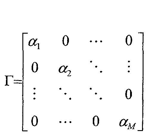
- N=[n(1),n(2),...,n(N)] where n(i) is the vector of the noise signals sampled at time i. We suppose now that the source transmits a reference signal s i.e. in the context of DS-CDMA a sequence of pilot symbols. The preprocessing step is given by:
- It should be noted that if the received signals are not despread by the user code the columns of X exhibit redundancy. Conversely, if the received signals are despread by the user code, the correlation expressed in (20) is performed over a series of N symbols.
- Without loss of generality, we assume that s(n)s*(n)=1. We consider the case M=2 to simplify notations. It can be easily shown that:The noise on each antenna after preprocessing can be expressed as:
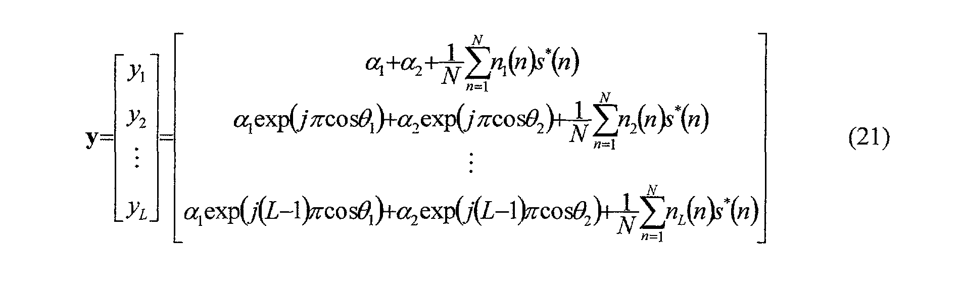 It is a white Gaussian complex noise with zero mean and variance σ2/N i.e. n ' / l∼
 (0,σ2/N). By using y instead of X in the estimation of R, we will show that we obtain a reduction of the noise level, in particular for the diagonal elements. We recall the expressions of the estimates of the spatial covariance matrix respectively without and with the preprocessing step:

- If we consider the diagonal elements, we may restrict our comparison without loss of generality to the element of the first row and first column of the matrix:


- The expressions are identical except for the last terms. The second terms in the expressions (25) and (26) are Gaussian random variables with zero mean and variance σ2/N.
- The noise elements n 1(n) are white Gaussian complex random variables, the real part and the imaginary part of which having zero mean and variance σ 2 / D=σ2/2, i.e. n 1(n)=n 1 R (n)+jn 1 I (n), with n 1 R(n)∼
- Thus, if we denote Y and Y' the last terms of expressions (25) and (26) respectively, we have:

 It can be shown that Y and Y' are central chi-square distributed random variables with respectively 2N and 2 degrees of freedom. The first two moments of a central chi-square-distributed random variable
 with n degrees of freedom, each Zi being independent and identically distributed Gaussian random variables with zero mean and variance σ2, are E[Z]=nσ 2 and E[Z 2]=2nσ4+n 2σ4. From the values of these moments we can derive the means as well as the variances σ 2 / Y and σ 2 / Y' of Y and Y' respectively: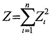
- The mean value of the noise corrupting the diagonal elements has therefore been reduced by a factor N. Similarly, as far as the variance is concerned, the contribution of the last term in (26) is N times smaller than the contribution of the last term in (25). Therefore by using a pilot-aided estimation of the covariance matrix instead of the blind estimation of the prior art, we have removed the bias on the diagonal elements and reduced the noise variance on the both diagonal and off-diagonal elements. Furtheremore, it is important to note that the estimation of the number of paths according to the MDL criterion benefits also from the reduction of noise level since it is also based on the estimate of the covariance matrix.
- Let us now consider the case where more than one source, e.g. two sources S1 and S2 are present in the far field and where the signal propagation between each of the sources and the array involves only one propagation path. This assumption is equivalent to having two incoherent sources in two distinct directions.
- The output of the preprocessing step for the source S1 can be written, similar to (21):where s1(n) and s2(n), n=1,..,N are pilot sequences transmitted by S1 and S2 respectively and
 l=1,..,L. The calculation of R 1 / P=y 1 y H / 1 gives therefore a spatial spectral density |α1|2 in the direction 1 and
 in the direction 2. The peak in the direction 2 is therefore reduced by a factor proportional to the cross-correlation between the two sequences (the pilot sequences are ideally orthogonal). The preprocessing step prior to the covariance matrix estimation leads here again to a more accurate determination of the number of paths and their respective angles of incidence.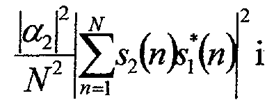
- Fig. 2 shows a DS-CDMA receiver using the pilot-aided DOA estimation according to the invention. The receiver comprises an array of antennas 2001,..,200L receiving the signals transmitted by a plurality M of users. For the sake of clarity, only the sub-sytem of the receiver relative to user #1 has been illustrated. It should be clear that in fact M such sub-sytems operate in parallel in the receiver.
- Each received signal is despread with the user #1 spreading code c1 . More precisely, the signal received by antenna 200ℓ is correlated in the correlators 210 1 / ℓ,..210 Q / ℓ with delayed versions of the spreading codes aligned with the times of arrival τ1,..,τ Q given by a delay profile analyzer (not shown). A plurality of beamformers 2401,..,240Q are provided, each beamformer 240 q q=1,...,Q receiving a set of L despread signals corresponding to a plurality mq of synchronous paths. For example, 2401 inputs despread signals having propagated along synchronous paths all arriving at time τ1 and forms m 1 beams in the respective directions of these paths. The received signals are correlated in 2150,..,215L with a sequence of pilot symbols s1(n) of user #1 (in despread form). An estimate R 1 / P of the covariance matrix is obtained in 2201 from the vector of correlated signals y1 . The matrix R 1 / P is then used by a DOA estimator 2301 implementing one of the DOA estimation algorithms reviewed above e.g. one of the conventional, Capon, MUSIC or ESPRIT algorithms. A complex vector w1 of weighting coefficients is obtained from the estimated DOAs and transmitted to beamformer 2401. The vector w1 achieves a beamforming in the m 1 directions of the synchronous paths. The output signals z q / 1 of the beamformers 240q, q=1,..,Q are then MRC (Maximum Ratio Combining) combined in 2501 to give an estimate r1 of the signal transmitted by user #1.
- Alternately, in a second embodiment of the invention illustrated in Fig. 3, the different paths originating from a user are combined in a RAKE receiver before being subjected to beamforming. In this embodiment only one beamformer (instead of Q) is needed per user. Here again, Fig. 3 shows only the sub-sytem of the receiver relative to user #1. It should be clear that in fact M such sub-sytems operate in parallel in the receiver. The RAKE receivers 3601,..,360L input the signals respectively received by the antennas 3001,..,300L and combine the paths originating from user #1. The signals output from the RAKE receivers are then correlated in 3150,..,315L with a sequence of pilot symbols s1(n) of user #1 (in despread form). An estimate RP of the covariance matrix is obtained in 3201 from the vector of correlated signals y 1. The DOAs are then estimated in 330 from RP and the vector of weighting coefficients is transmitted to the beamformer 340.
- In a third embodiment, illustrated in Fig. 4, the beamforming is realized before despreading (i.e. at the chip rate). In this embodiment only one beamformer is needed per user. Since it operates wide-band, it uses delays as well as DOAs. The beamformers 4401,..,440M are provided for the users #1,..,#M respectively. For a given user #j, a set of correlators 4151,..,415L perform the correlation of the received signals with the pilot sequence (in spread form) of said user. More precisely, this correlation is performed at different frequencies (within the spectral band) of the received signals and the pilot sequence signal. For each user #j=#1,..,#M, the results of the correlation are exploited in block 425 j by a MUSIC 2D algorithm, kown as such, which gives the delays and DOAs for the paths originating from user # j . The different paths are then combined in an MRC combiner 460 j to provide an estimate r1 of the signal transmitted by user #1.
- Although the invention has been essentially described within the context of DS-CDMA, it should be understood that it can be applied to any passive beamforming system when sources to be located transmit reference signals.
Claims (12)
- Method for estimating a direction of arrival of a signal transmitted by a signal source and received by an antenna array, said method estimating the covariance matrix of the signals respectively received by the antennas of the array and deriving therefrom a direction of arrival, characterised in that said received signals are correlated with a reference signal transmitted by said source prior to be submitted to the covariance matrix estimation.
- Method according to claim 1, characterised in that the direction of arrival is obtained from said estimate of the covariance matrix by carrying out a MUSIC type algorithm.
- Method according to claim 1, characterised in that the direction of arrival is obtained from said estimate of the covariance matrix by carrying out an ESPRIT type algorithm.
- Method according to any of the preceding claims, characterised in that the signal transmitted by said signal source having propagated to the antenna array along a plurality of propagation paths, said received signals are grouped into sets of synchronously received signals, the signals of each set being correlated with a reference signal transmitted by said source prior to be submitted to the covariance matrix estimation.
- Method according to claim 1, characterised in that, the signal transmitted by said signal source being DS-CDMA coded with a spreading code, the received signals are first despread and the despread signals are then correlated with a sequence of pilot symbols prior to be submitted to the covariance matrix estimation.
- Method according to claim 5, characterised in that the despread signals are weighted by weighting coefficients and added to form a beam in a beamforming step, the vector of weighting coefficients being derived from the estimate of said covariance matrix.
- Method according to claim 6, characterised in that a plurality of beamforming steps performed for a plurality of synchronous received signals, the respective outputs of the beamforming steps are MRC combined.
- Method according to claim 1, characterised in that, the signal transmitted by said signal source being DS-CDMA coded with a spreading code, the plurality of received signals are first despread and combined in the same plurality of RAKE receivers, the signals respectively output from said RAKE receivers being each correlated with a sequence of pilot symbols prior to be submitted to covariance matrix estimation.
- Method according to claim 8, characterised in that the signals output from the RAKE receivers are weighted by weighting coefficients and added to form a beam in a beamforming step, the vector of weighting coefficients being derived from the estimate of said covariance matrix.
- Method according to claim 1, characterised in that, the signal transmitted by said signal source being DS-CDMA coded by a spreading code, the plurality of received signals are each correlated with spread pilot symbols before being subjected to a MUSIC 2D estimation step.
- Method according to claim 10, characterised in that the plurality of received signals is subjected to a beamforming step using delays and directions of arrival output by said MUSIC 2D estimation step.
- Method according to claim 11, characterised that the signals output from said beamforming step for said directions of arrival are MRC combined.
Priority Applications (6)
| Application Number | Priority Date | Filing Date | Title |
|---|---|---|---|
| AT01401120T ATE463749T1 (en) | 2001-04-27 | 2001-04-27 | METHOD FOR ESTIMATING INCOME DIRECTION |
| DE60141741T DE60141741D1 (en) | 2001-04-27 | 2001-04-27 | Infalling direction estimation method |
| EP01401120A EP1253434B1 (en) | 2001-04-27 | 2001-04-27 | Method for estimating a direction of arrival |
| US10/126,543 US6717979B2 (en) | 2001-04-27 | 2002-04-22 | Method for estimating a direction of arrival |
| JP2002125139A JP2003004834A (en) | 2001-04-27 | 2002-04-26 | Method for estimating direction of arrival of signal |
| CN02120097.1A CN1254692C (en) | 2001-04-27 | 2002-04-26 | Arrival bearing estimating method |
Applications Claiming Priority (1)
| Application Number | Priority Date | Filing Date | Title |
|---|---|---|---|
| EP01401120A EP1253434B1 (en) | 2001-04-27 | 2001-04-27 | Method for estimating a direction of arrival |
Publications (2)
| Publication Number | Publication Date |
|---|---|
| EP1253434A1 true EP1253434A1 (en) | 2002-10-30 |
| EP1253434B1 EP1253434B1 (en) | 2010-04-07 |
Family
ID=8182708
Family Applications (1)
| Application Number | Title | Priority Date | Filing Date |
|---|---|---|---|
| EP01401120A Expired - Lifetime EP1253434B1 (en) | 2001-04-27 | 2001-04-27 | Method for estimating a direction of arrival |
Country Status (6)
| Country | Link |
|---|---|
| US (1) | US6717979B2 (en) |
| EP (1) | EP1253434B1 (en) |
| JP (1) | JP2003004834A (en) |
| CN (1) | CN1254692C (en) |
| AT (1) | ATE463749T1 (en) |
| DE (1) | DE60141741D1 (en) |
Cited By (10)
| Publication number | Priority date | Publication date | Assignee | Title |
|---|---|---|---|---|
| WO2008105748A1 (en) * | 2007-02-26 | 2008-09-04 | Temel Engin Tuncer | Method and apparatus for the joint detection of the number of signal sources and their direction of arrivals |
| CN101111998B (en) * | 2004-10-27 | 2012-08-22 | 塔莱斯公司 | Method for characterising emitters by the association of parameters related to the same radio emitter |
| CN101442350B (en) * | 2007-11-22 | 2012-09-26 | 中兴通讯股份有限公司 | Estimation method for arrival angle |
| CN105022026A (en) * | 2015-07-08 | 2015-11-04 | 陕西理工学院 | Two-dimensional arrival angle estimation method of L-shaped array |
| CN109061555A (en) * | 2018-08-27 | 2018-12-21 | 电子科技大学 | Relevant DOA estimation method is mixed under nested array |
| CN111142097A (en) * | 2019-07-05 | 2020-05-12 | 武汉工程大学 | A Target Direction Estimation Method in AM Broadcast External Radiator Radar |
| CN111521968A (en) * | 2020-05-22 | 2020-08-11 | 南京理工大学 | Underdetermined DOA estimation method based on target space diversity |
| CN112731280A (en) * | 2020-12-24 | 2021-04-30 | 南京航空航天大学 | ESPRIT-DOA estimation method under co-prime array mixed noise environment |
| CN113093093A (en) * | 2021-04-07 | 2021-07-09 | 南京邮电大学 | Vehicle positioning method based on linear array direction of arrival estimation |
| CN113687296A (en) * | 2021-07-09 | 2021-11-23 | 中国人民解放军战略支援部队信息工程大学 | A direction finding method for underwater target radiation noise coherent source based on numerical calculation of array signals |
Families Citing this family (35)
| Publication number | Priority date | Publication date | Assignee | Title |
|---|---|---|---|---|
| JP4309110B2 (en) * | 2002-09-27 | 2009-08-05 | パナソニック株式会社 | Adaptive antenna wireless communication device |
| US6987482B2 (en) * | 2003-09-19 | 2006-01-17 | Intel Corporation | Wireless signal processing methods and apparatuses including directions of arrival estimation |
| US8077758B2 (en) * | 2005-02-10 | 2011-12-13 | Interdigital Technology Corporation | Signal separation techniques to provide robust spread spectrum signal decoding |
| JP4805591B2 (en) * | 2005-03-17 | 2011-11-02 | 富士通株式会社 | Radio wave arrival direction tracking method and radio wave arrival direction tracking device |
| KR100832319B1 (en) | 2005-12-06 | 2008-05-26 | 삼성전자주식회사 | Beam-forming apparatus and method in smart antenna systems |
| JP4990919B2 (en) * | 2006-03-09 | 2012-08-01 | フンダシオ プリバーダ セントレ テクノロジック デ テレコミュニケーションズ デ カタルーニャ | Direction-of-arrival estimation method and system in scenarios with low intensity or small sample size |
| CN101038333B (en) * | 2007-04-13 | 2010-05-19 | 北京工业大学 | Doppler radio direction finding method |
| CN101232316B (en) * | 2008-01-17 | 2012-05-09 | 华南理工大学 | A Direction of Arrival Estimation Method Based on Mobile WIMAX |
| JP2010133905A (en) * | 2008-12-08 | 2010-06-17 | Nippon Telegr & Teleph Corp <Ntt> | Radio unit and method for estimating radio wave arrival direction |
| WO2010092421A1 (en) * | 2009-02-16 | 2010-08-19 | The B.T.I. Company | Wireless communication systems and methods with source localization and self-calibration |
| KR20120031700A (en) * | 2010-09-27 | 2012-04-04 | 삼성전자주식회사 | Method and apparatus of interference aligning using feedforward index in hierarchical cell communication system |
| US8483260B2 (en) * | 2010-09-29 | 2013-07-09 | Telefonaktiebolaget Lm Ericsson (Publ) | Covariance factor matrix reuse |
| CN102385049A (en) * | 2011-08-10 | 2012-03-21 | 西安交通大学 | Two-dimensional coherent signal direction estimation method based on double parallel arrays |
| CN102662158B (en) * | 2012-05-04 | 2013-08-14 | 电子科技大学 | Quick processing method for sensor antenna array received signals |
| CN102721943B (en) * | 2012-06-11 | 2014-03-12 | 西安交通大学 | L type sensor array-based incoherent signal two-dimensional direction-of-arrival tracking method and device |
| KR102008467B1 (en) * | 2012-12-27 | 2019-08-07 | 삼성전자주식회사 | Uplink power control method and apparatus in a beamforming based wireless communication system |
| CN103278796B (en) * | 2013-05-21 | 2015-06-17 | 西安电子科技大学 | Conical surface conformal array multi-parameter joint estimation method |
| KR101498646B1 (en) * | 2013-12-03 | 2015-03-04 | 충남대학교산학협력단 | DOA Estimation Apparatus and Method in Multi-Jammer Environments |
| CN103760519B (en) * | 2014-01-24 | 2016-02-03 | 深圳大学 | High resolution DOA estimation method and system |
| CN104035069B (en) * | 2014-06-18 | 2016-08-17 | 西安交通大学 | Arrowband based on partial correction linear array symmetrically and evenly near-field signals source location method |
| CN104298850A (en) * | 2014-07-18 | 2015-01-21 | 哈尔滨工业大学深圳研究生院 | Coherent signal direction finding method and system with unknown signal source number |
| CN105372623B (en) * | 2015-12-15 | 2018-08-07 | 吉林大学 | A kind of the information source elevation angle and azimuth method of estimation based on L-type array |
| CN108886400B (en) * | 2016-04-12 | 2022-03-01 | 三菱电机株式会社 | Receiving apparatus, receiving method, and computer-readable recording medium |
| CN107621623B (en) * | 2016-07-13 | 2020-04-10 | 智易科技股份有限公司 | Signal direction detection method and beam former using same |
| EP3596484B1 (en) * | 2017-05-10 | 2022-06-01 | Huawei Technologies Co., Ltd. | Method and device for estimating a time of arrival of a radio signal |
| CN108761381B (en) * | 2018-04-09 | 2021-05-04 | 武汉虹信科技发展有限责任公司 | Target information source detection method based on array antenna |
| CN108713323B (en) * | 2018-05-30 | 2019-11-15 | 歌尔股份有限公司 | Method and device for estimating direction of arrival |
| WO2020205364A1 (en) * | 2019-03-29 | 2020-10-08 | Denso International America, Inc. | Passive entry/passive start systems implementing music algorithm based angle of arrival determinations for signals received via circular polarized antennas |
| CN110082710B (en) * | 2019-05-15 | 2023-05-26 | 苏州经贸职业技术学院 | Two-dimensional Angle of Arrival Estimation Method Based on Sparse Arrays with Lattice-Free Atom Norm |
| CN110213186A (en) * | 2019-07-02 | 2019-09-06 | 南京理工大学 | The angle of arrival and signal-noise ratio estimation method of ESPRIT based on mixed structure |
| CN111323744B (en) * | 2020-03-19 | 2022-12-13 | 哈尔滨工程大学 | Target number and target angle estimation method based on MDL (minimization drive language) criterion |
| CN112666513B (en) * | 2020-12-11 | 2024-05-07 | 中国人民解放军63892部队 | An Improved MUSIC Direction of Arrival Estimation Method |
| KR102864489B1 (en) * | 2021-11-11 | 2025-09-25 | 썬전 샥 컴퍼니, 리미티드 | Method and system for detecting voice activity, method and system for enhancing voice |
| CN116106854B (en) * | 2023-04-13 | 2023-06-23 | 湖南工商大学 | A method for estimating the number of sources by combining difference matrix and time delay method |
| CN119644241B (en) * | 2024-12-03 | 2025-10-24 | 电子科技大学 | A sub-snapshot 2D-MUSIC direction finding method based on spatial translation invariance |
Citations (2)
| Publication number | Priority date | Publication date | Assignee | Title |
|---|---|---|---|---|
| US6141567A (en) * | 1999-06-07 | 2000-10-31 | Arraycomm, Inc. | Apparatus and method for beamforming in a changing-interference environment |
| US6215814B1 (en) * | 1998-09-14 | 2001-04-10 | Nokia Networks Oy | RAKE receiver |
Family Cites Families (6)
| Publication number | Priority date | Publication date | Assignee | Title |
|---|---|---|---|---|
| US5262789A (en) * | 1992-04-30 | 1993-11-16 | General Electric Company | Source identification system for closely separated spatial sources |
| JP3233088B2 (en) * | 1998-01-22 | 2001-11-26 | 松下電器産業株式会社 | Directivity control antenna device |
| JP3406831B2 (en) * | 1998-03-19 | 2003-05-19 | 富士通株式会社 | Array antenna system for wireless base station |
| JP2988463B2 (en) * | 1998-03-24 | 1999-12-13 | 日本電気株式会社 | Direction finding device and measurement result processing device therefor |
| JP3920483B2 (en) * | 1998-12-28 | 2007-05-30 | 株式会社東芝 | Radio wave arrival direction estimation method and antenna apparatus |
| US6075484A (en) * | 1999-05-03 | 2000-06-13 | Motorola, Inc. | Method and apparatus for robust estimation of directions of arrival for antenna arrays |
-
2001
- 2001-04-27 AT AT01401120T patent/ATE463749T1/en not_active IP Right Cessation
- 2001-04-27 DE DE60141741T patent/DE60141741D1/en not_active Expired - Lifetime
- 2001-04-27 EP EP01401120A patent/EP1253434B1/en not_active Expired - Lifetime
-
2002
- 2002-04-22 US US10/126,543 patent/US6717979B2/en not_active Expired - Lifetime
- 2002-04-26 CN CN02120097.1A patent/CN1254692C/en not_active Expired - Lifetime
- 2002-04-26 JP JP2002125139A patent/JP2003004834A/en active Pending
Patent Citations (2)
| Publication number | Priority date | Publication date | Assignee | Title |
|---|---|---|---|---|
| US6215814B1 (en) * | 1998-09-14 | 2001-04-10 | Nokia Networks Oy | RAKE receiver |
| US6141567A (en) * | 1999-06-07 | 2000-10-31 | Arraycomm, Inc. | Apparatus and method for beamforming in a changing-interference environment |
Non-Patent Citations (3)
| Title |
|---|
| FORSTER P ET AL: "Maximum likelihood multichannel estimation under reduced rank constraint", PROCEEDINGS OF THE 1998 IEEE INTERNATIONAL CONFERENCE ON ACOUSTICS, SPEECH AND SIGNAL PROCESSING, ICASSP '98 (CAT. NO.98CH36181), PROCEEDINGS OF THE 1998 IEEE INTERNATIONAL CONFERENCE ON ACOUSTICS, SPEECH AND SIGNAL PROCESSING, SEATTLE, WA, USA, 12-1, 1998, New York, NY, USA, IEEE, USA, pages 3317 - 3320 vol.6, XP002176648, ISBN: 0-7803-4428-6 * |
| KRIM H ET AL: "Two decades of array signal processing research: the parametric approach", IEEE SIGNAL PROCESSING MAGAZINE, JULY 1996, IEEE, USA, vol. 13, no. 4, pages 67 - 94, XP002176649, ISSN: 1053-5888 * |
| ROY R ET AL: "ESPRIT-estimation of signal parameters via rotational invariance techniques", IEEE TRANSACTIONS ON ACOUSTICS, SPEECH AND SIGNAL PROCESSING, JULY 1989, USA, vol. 37, no. 7, pages 984 - 995, XP002176647, ISSN: 0096-3518 * |
Cited By (14)
| Publication number | Priority date | Publication date | Assignee | Title |
|---|---|---|---|---|
| CN101111998B (en) * | 2004-10-27 | 2012-08-22 | 塔莱斯公司 | Method for characterising emitters by the association of parameters related to the same radio emitter |
| WO2008105748A1 (en) * | 2007-02-26 | 2008-09-04 | Temel Engin Tuncer | Method and apparatus for the joint detection of the number of signal sources and their direction of arrivals |
| CN101442350B (en) * | 2007-11-22 | 2012-09-26 | 中兴通讯股份有限公司 | Estimation method for arrival angle |
| CN105022026A (en) * | 2015-07-08 | 2015-11-04 | 陕西理工学院 | Two-dimensional arrival angle estimation method of L-shaped array |
| CN105022026B (en) * | 2015-07-08 | 2017-07-07 | 陕西理工学院 | The two-dimentional angle estimation method of L-type array |
| CN109061555A (en) * | 2018-08-27 | 2018-12-21 | 电子科技大学 | Relevant DOA estimation method is mixed under nested array |
| CN111142097A (en) * | 2019-07-05 | 2020-05-12 | 武汉工程大学 | A Target Direction Estimation Method in AM Broadcast External Radiator Radar |
| CN111521968A (en) * | 2020-05-22 | 2020-08-11 | 南京理工大学 | Underdetermined DOA estimation method based on target space diversity |
| CN112731280A (en) * | 2020-12-24 | 2021-04-30 | 南京航空航天大学 | ESPRIT-DOA estimation method under co-prime array mixed noise environment |
| CN112731280B (en) * | 2020-12-24 | 2023-11-07 | 南京航空航天大学 | ESPRIT-DOA estimation method in coprime array mixed noise environment |
| CN113093093A (en) * | 2021-04-07 | 2021-07-09 | 南京邮电大学 | Vehicle positioning method based on linear array direction of arrival estimation |
| CN113093093B (en) * | 2021-04-07 | 2023-08-18 | 南京邮电大学 | Vehicle positioning method based on linear array direction of arrival estimation |
| CN113687296A (en) * | 2021-07-09 | 2021-11-23 | 中国人民解放军战略支援部队信息工程大学 | A direction finding method for underwater target radiation noise coherent source based on numerical calculation of array signals |
| CN113687296B (en) * | 2021-07-09 | 2023-05-16 | 中国人民解放军战略支援部队信息工程大学 | Underwater target radiation noise coherent information source direction finding method based on array signal numerical calculation |
Also Published As
| Publication number | Publication date |
|---|---|
| ATE463749T1 (en) | 2010-04-15 |
| US6717979B2 (en) | 2004-04-06 |
| CN1254692C (en) | 2006-05-03 |
| US20030012262A1 (en) | 2003-01-16 |
| JP2003004834A (en) | 2003-01-08 |
| EP1253434B1 (en) | 2010-04-07 |
| CN1384368A (en) | 2002-12-11 |
| DE60141741D1 (en) | 2010-05-20 |
Similar Documents
| Publication | Publication Date | Title |
|---|---|---|
| EP1253434B1 (en) | Method for estimating a direction of arrival | |
| Foutz et al. | Narrowband direction of arrival estimation for antenna arrays | |
| US7084812B2 (en) | Method and device for tracking the directions-of-arrival of radio waves | |
| US6208295B1 (en) | Method for processing radio signals that are subject to unwanted change during propagation | |
| US7619579B2 (en) | Smart antenna system with improved localization of polarized sources | |
| US6310704B1 (en) | Communication apparatus for transmitting and receiving signals over a fiber-optic waveguide using different frequency bands of light | |
| US7391370B2 (en) | Method and apparatus for adaptive direction estimation of radio waves | |
| US6697633B1 (en) | Method permitting increased frequency re-use in a communication network, by recovery of transmitted information from multiple cochannel signals | |
| US6535666B1 (en) | Method and apparatus for separating signals transmitted over a waveguide | |
| US6658234B1 (en) | Method for extending the effective dynamic range of a radio receiver system | |
| US7228244B2 (en) | Method and apparatus for direction-of-arrival tracking and their application to beamforming at base-station | |
| US6215983B1 (en) | Method and apparatus for complex phase equalization for use in a communication system | |
| US20050285788A1 (en) | Technique for direction-of-arrival estimation without eigendecomposition and its application to beamforming at base station | |
| US20020065664A1 (en) | System and method for linear prediction | |
| EP1345337A2 (en) | Adaptive antenna base station apparatus with direction of arrival estimation | |
| Zhang et al. | Estimation of two-dimensional direction-of-arrival for uncorrelated and coherent signals with low complexity | |
| Hoang et al. | Low-complexity compressed sensing-aided coherent direction-of-arrival estimation for large-scale lens antenna array | |
| Aounallah | Robust min-norm algorithms for coherent sources DOA estimation based on Toeplitz matrix reconstruction methods | |
| US20030157967A1 (en) | Antenna conbiners | |
| Ottersten et al. | A statistical approach to subspace based estimation with applications in telecommunications | |
| Tayem et al. | Capon root-MUSIC-like direction of arrival estimation based on real data | |
| Varum et al. | Detect and pointing algorithm's performance for a planar smart antenna array: a review | |
| Ng et al. | Diversely polarised arrays in DS-CDMA: A space-time channel estimation approach | |
| Tayem et al. | A fast algorithm for direction of arrival estimation in multipath environments | |
| Morrison et al. | High-resolution iterative DOA algorithm for W-CDMA space-time receiver structures |
Legal Events
| Date | Code | Title | Description |
|---|---|---|---|
| PUAI | Public reference made under article 153(3) epc to a published international application that has entered the european phase |
Free format text: ORIGINAL CODE: 0009012 |
|
| AK | Designated contracting states |
Kind code of ref document: A1 Designated state(s): AT BE CH CY DE DK ES FI FR GB GR IE IT LI LU MC NL PT SE TR |
|
| AX | Request for extension of the european patent |
Free format text: AL;LT;LV;MK;RO;SI |
|
| 17P | Request for examination filed |
Effective date: 20021206 |
|
| RAP1 | Party data changed (applicant data changed or rights of an application transferred) |
Owner name: MITSUBISHI ELECTRIC INFORMATION TECHNOLOGY CENTRE |
|
| AKX | Designation fees paid |
Designated state(s): AT BE CH CY DE DK ES FI FR GB GR IE IT LI LU MC NL PT SE TR |
|
| 17Q | First examination report despatched |
Effective date: 20030731 |
|
| RAP1 | Party data changed (applicant data changed or rights of an application transferred) |
Owner name: MITSUBISHI ELECTRIC R&D CENTRE EUROPE B.V. |
|
| GRAP | Despatch of communication of intention to grant a patent |
Free format text: ORIGINAL CODE: EPIDOSNIGR1 |
|
| GRAS | Grant fee paid |
Free format text: ORIGINAL CODE: EPIDOSNIGR3 |
|
| GRAA | (expected) grant |
Free format text: ORIGINAL CODE: 0009210 |
|
| AK | Designated contracting states |
Kind code of ref document: B1 Designated state(s): AT BE CH CY DE DK ES FI FR GB GR IE IT LI LU MC NL PT SE TR |
|
| REG | Reference to a national code |
Ref country code: GB Ref legal event code: FG4D |
|
| REG | Reference to a national code |
Ref country code: CH Ref legal event code: EP |
|
| REG | Reference to a national code |
Ref country code: IE Ref legal event code: FG4D |
|
| REF | Corresponds to: |
Ref document number: 60141741 Country of ref document: DE Date of ref document: 20100520 Kind code of ref document: P |
|
| REG | Reference to a national code |
Ref country code: NL Ref legal event code: VDEP Effective date: 20100407 |
|
| PG25 | Lapsed in a contracting state [announced via postgrant information from national office to epo] |
Ref country code: ES Free format text: LAPSE BECAUSE OF FAILURE TO SUBMIT A TRANSLATION OF THE DESCRIPTION OR TO PAY THE FEE WITHIN THE PRESCRIBED TIME-LIMIT Effective date: 20100718 Ref country code: SE Free format text: LAPSE BECAUSE OF FAILURE TO SUBMIT A TRANSLATION OF THE DESCRIPTION OR TO PAY THE FEE WITHIN THE PRESCRIBED TIME-LIMIT Effective date: 20100407 Ref country code: NL Free format text: LAPSE BECAUSE OF FAILURE TO SUBMIT A TRANSLATION OF THE DESCRIPTION OR TO PAY THE FEE WITHIN THE PRESCRIBED TIME-LIMIT Effective date: 20100407 |
|
| PG25 | Lapsed in a contracting state [announced via postgrant information from national office to epo] |
Ref country code: MC Free format text: LAPSE BECAUSE OF NON-PAYMENT OF DUE FEES Effective date: 20100430 Ref country code: AT Free format text: LAPSE BECAUSE OF FAILURE TO SUBMIT A TRANSLATION OF THE DESCRIPTION OR TO PAY THE FEE WITHIN THE PRESCRIBED TIME-LIMIT Effective date: 20100407 Ref country code: FI Free format text: LAPSE BECAUSE OF FAILURE TO SUBMIT A TRANSLATION OF THE DESCRIPTION OR TO PAY THE FEE WITHIN THE PRESCRIBED TIME-LIMIT Effective date: 20100407 |
|
| REG | Reference to a national code |
Ref country code: CH Ref legal event code: PL |
|
| PG25 | Lapsed in a contracting state [announced via postgrant information from national office to epo] |
Ref country code: GR Free format text: LAPSE BECAUSE OF FAILURE TO SUBMIT A TRANSLATION OF THE DESCRIPTION OR TO PAY THE FEE WITHIN THE PRESCRIBED TIME-LIMIT Effective date: 20100708 Ref country code: CY Free format text: LAPSE BECAUSE OF FAILURE TO SUBMIT A TRANSLATION OF THE DESCRIPTION OR TO PAY THE FEE WITHIN THE PRESCRIBED TIME-LIMIT Effective date: 20100407 |
|
| PG25 | Lapsed in a contracting state [announced via postgrant information from national office to epo] |
Ref country code: IE Free format text: LAPSE BECAUSE OF NON-PAYMENT OF DUE FEES Effective date: 20100427 Ref country code: DK Free format text: LAPSE BECAUSE OF FAILURE TO SUBMIT A TRANSLATION OF THE DESCRIPTION OR TO PAY THE FEE WITHIN THE PRESCRIBED TIME-LIMIT Effective date: 20100407 Ref country code: PT Free format text: LAPSE BECAUSE OF FAILURE TO SUBMIT A TRANSLATION OF THE DESCRIPTION OR TO PAY THE FEE WITHIN THE PRESCRIBED TIME-LIMIT Effective date: 20100809 |
|
| PLBE | No opposition filed within time limit |
Free format text: ORIGINAL CODE: 0009261 |
|
| STAA | Information on the status of an ep patent application or granted ep patent |
Free format text: STATUS: NO OPPOSITION FILED WITHIN TIME LIMIT |
|
| PG25 | Lapsed in a contracting state [announced via postgrant information from national office to epo] |
Ref country code: CH Free format text: LAPSE BECAUSE OF NON-PAYMENT OF DUE FEES Effective date: 20100430 Ref country code: BE Free format text: LAPSE BECAUSE OF FAILURE TO SUBMIT A TRANSLATION OF THE DESCRIPTION OR TO PAY THE FEE WITHIN THE PRESCRIBED TIME-LIMIT Effective date: 20100407 Ref country code: LI Free format text: LAPSE BECAUSE OF NON-PAYMENT OF DUE FEES Effective date: 20100430 |
|
| 26N | No opposition filed |
Effective date: 20110110 |
|
| PG25 | Lapsed in a contracting state [announced via postgrant information from national office to epo] |
Ref country code: IT Free format text: LAPSE BECAUSE OF FAILURE TO SUBMIT A TRANSLATION OF THE DESCRIPTION OR TO PAY THE FEE WITHIN THE PRESCRIBED TIME-LIMIT Effective date: 20100407 |
|
| PG25 | Lapsed in a contracting state [announced via postgrant information from national office to epo] |
Ref country code: LU Free format text: LAPSE BECAUSE OF NON-PAYMENT OF DUE FEES Effective date: 20100427 |
|
| PG25 | Lapsed in a contracting state [announced via postgrant information from national office to epo] |
Ref country code: TR Free format text: LAPSE BECAUSE OF FAILURE TO SUBMIT A TRANSLATION OF THE DESCRIPTION OR TO PAY THE FEE WITHIN THE PRESCRIBED TIME-LIMIT Effective date: 20100407 |
|
| REG | Reference to a national code |
Ref country code: FR Ref legal event code: PLFP Year of fee payment: 16 |
|
| REG | Reference to a national code |
Ref country code: DE Ref legal event code: R084 Ref document number: 60141741 Country of ref document: DE |
|
| REG | Reference to a national code |
Ref country code: GB Ref legal event code: 746 Effective date: 20160519 |
|
| REG | Reference to a national code |
Ref country code: FR Ref legal event code: PLFP Year of fee payment: 17 |
|
| REG | Reference to a national code |
Ref country code: FR Ref legal event code: PLFP Year of fee payment: 18 |
|
| REG | Reference to a national code |
Ref country code: GB Ref legal event code: S47 Free format text: CANCELLATION OF ENTRY; APPLICATION FOR CANCELLATION OF ENTRY ON THE REGISTER OF A LICENCE OF RIGHT FILED ON 22 FEBRUARY 2018 |
|
| REG | Reference to a national code |
Ref country code: GB Ref legal event code: S47 Free format text: ENTRY CANCELLED; NOTICE IS HEREBY GIVEN THAT THE LICENCE OF RIGHT ENTRY ON THE REGISTER FOR THE FOLLOWING PATENT WAS CANCELLED ON 6 JUNE 2018 MITSUBISHI ELECTRIC R&D CENTRE EUROPE B.V. METHOD FOR ESTIMATING A DIRECTION OF ARRIVAL |
|
| PGFP | Annual fee paid to national office [announced via postgrant information from national office to epo] |
Ref country code: FR Payment date: 20200312 Year of fee payment: 20 |
|
| PGFP | Annual fee paid to national office [announced via postgrant information from national office to epo] |
Ref country code: DE Payment date: 20200415 Year of fee payment: 20 |
|
| PGFP | Annual fee paid to national office [announced via postgrant information from national office to epo] |
Ref country code: GB Payment date: 20200416 Year of fee payment: 20 |
|
| REG | Reference to a national code |
Ref country code: DE Ref legal event code: R071 Ref document number: 60141741 Country of ref document: DE |
|
| REG | Reference to a national code |
Ref country code: GB Ref legal event code: PE20 Expiry date: 20210426 |
|
| PG25 | Lapsed in a contracting state [announced via postgrant information from national office to epo] |
Ref country code: GB Free format text: LAPSE BECAUSE OF EXPIRATION OF PROTECTION Effective date: 20210426 |