EP1253372A2 - Discharge lamp having improved shield - Google Patents
Discharge lamp having improved shield Download PDFInfo
- Publication number
- EP1253372A2 EP1253372A2 EP02252961A EP02252961A EP1253372A2 EP 1253372 A2 EP1253372 A2 EP 1253372A2 EP 02252961 A EP02252961 A EP 02252961A EP 02252961 A EP02252961 A EP 02252961A EP 1253372 A2 EP1253372 A2 EP 1253372A2
- Authority
- EP
- European Patent Office
- Prior art keywords
- reflector
- assembly
- light source
- discharge lamp
- openings
- Prior art date
- Legal status (The legal status is an assumption and is not a legal conclusion. Google has not performed a legal analysis and makes no representation as to the accuracy of the status listed.)
- Withdrawn
Links
Images
Classifications
-
- F—MECHANICAL ENGINEERING; LIGHTING; HEATING; WEAPONS; BLASTING
- F21—LIGHTING
- F21V—FUNCTIONAL FEATURES OR DETAILS OF LIGHTING DEVICES OR SYSTEMS THEREOF; STRUCTURAL COMBINATIONS OF LIGHTING DEVICES WITH OTHER ARTICLES, NOT OTHERWISE PROVIDED FOR
- F21V25/00—Safety devices structurally associated with lighting devices
-
- F—MECHANICAL ENGINEERING; LIGHTING; HEATING; WEAPONS; BLASTING
- F21—LIGHTING
- F21V—FUNCTIONAL FEATURES OR DETAILS OF LIGHTING DEVICES OR SYSTEMS THEREOF; STRUCTURAL COMBINATIONS OF LIGHTING DEVICES WITH OTHER ARTICLES, NOT OTHERWISE PROVIDED FOR
- F21V29/00—Protecting lighting devices from thermal damage; Cooling or heating arrangements specially adapted for lighting devices or systems
- F21V29/50—Cooling arrangements
- F21V29/502—Cooling arrangements characterised by the adaptation for cooling of specific components
- F21V29/505—Cooling arrangements characterised by the adaptation for cooling of specific components of reflectors
-
- F—MECHANICAL ENGINEERING; LIGHTING; HEATING; WEAPONS; BLASTING
- F21—LIGHTING
- F21V—FUNCTIONAL FEATURES OR DETAILS OF LIGHTING DEVICES OR SYSTEMS THEREOF; STRUCTURAL COMBINATIONS OF LIGHTING DEVICES WITH OTHER ARTICLES, NOT OTHERWISE PROVIDED FOR
- F21V29/00—Protecting lighting devices from thermal damage; Cooling or heating arrangements specially adapted for lighting devices or systems
- F21V29/50—Cooling arrangements
- F21V29/70—Cooling arrangements characterised by passive heat-dissipating elements, e.g. heat-sinks
- F21V29/71—Cooling arrangements characterised by passive heat-dissipating elements, e.g. heat-sinks using a combination of separate elements interconnected by heat-conducting means, e.g. with heat pipes or thermally conductive bars between separate heat-sink elements
- F21V29/717—Cooling arrangements characterised by passive heat-dissipating elements, e.g. heat-sinks using a combination of separate elements interconnected by heat-conducting means, e.g. with heat pipes or thermally conductive bars between separate heat-sink elements using split or remote units thermally interconnected, e.g. by thermally conductive bars or heat pipes
-
- F—MECHANICAL ENGINEERING; LIGHTING; HEATING; WEAPONS; BLASTING
- F21—LIGHTING
- F21V—FUNCTIONAL FEATURES OR DETAILS OF LIGHTING DEVICES OR SYSTEMS THEREOF; STRUCTURAL COMBINATIONS OF LIGHTING DEVICES WITH OTHER ARTICLES, NOT OTHERWISE PROVIDED FOR
- F21V29/00—Protecting lighting devices from thermal damage; Cooling or heating arrangements specially adapted for lighting devices or systems
- F21V29/50—Cooling arrangements
- F21V29/70—Cooling arrangements characterised by passive heat-dissipating elements, e.g. heat-sinks
- F21V29/83—Cooling arrangements characterised by passive heat-dissipating elements, e.g. heat-sinks the elements having apertures, ducts or channels, e.g. heat radiation holes
-
- F—MECHANICAL ENGINEERING; LIGHTING; HEATING; WEAPONS; BLASTING
- F21—LIGHTING
- F21V—FUNCTIONAL FEATURES OR DETAILS OF LIGHTING DEVICES OR SYSTEMS THEREOF; STRUCTURAL COMBINATIONS OF LIGHTING DEVICES WITH OTHER ARTICLES, NOT OTHERWISE PROVIDED FOR
- F21V31/00—Gas-tight or water-tight arrangements
- F21V31/03—Gas-tight or water-tight arrangements with provision for venting
-
- G—PHYSICS
- G03—PHOTOGRAPHY; CINEMATOGRAPHY; ANALOGOUS TECHNIQUES USING WAVES OTHER THAN OPTICAL WAVES; ELECTROGRAPHY; HOLOGRAPHY
- G03B—APPARATUS OR ARRANGEMENTS FOR TAKING PHOTOGRAPHS OR FOR PROJECTING OR VIEWING THEM; APPARATUS OR ARRANGEMENTS EMPLOYING ANALOGOUS TECHNIQUES USING WAVES OTHER THAN OPTICAL WAVES; ACCESSORIES THEREFOR
- G03B21/00—Projectors or projection-type viewers; Accessories therefor
- G03B21/14—Details
- G03B21/20—Lamp housings
- G03B21/2006—Lamp housings characterised by the light source
- G03B21/2026—Gas discharge type light sources, e.g. arcs
-
- G—PHYSICS
- G03—PHOTOGRAPHY; CINEMATOGRAPHY; ANALOGOUS TECHNIQUES USING WAVES OTHER THAN OPTICAL WAVES; ELECTROGRAPHY; HOLOGRAPHY
- G03F—PHOTOMECHANICAL PRODUCTION OF TEXTURED OR PATTERNED SURFACES, e.g. FOR PRINTING, FOR PROCESSING OF SEMICONDUCTOR DEVICES; MATERIALS THEREFOR; ORIGINALS THEREFOR; APPARATUS SPECIALLY ADAPTED THEREFOR
- G03F7/00—Photomechanical, e.g. photolithographic, production of textured or patterned surfaces, e.g. printing surfaces; Materials therefor, e.g. comprising photoresists; Apparatus specially adapted therefor
- G03F7/70—Microphotolithographic exposure; Apparatus therefor
- G03F7/70008—Production of exposure light, i.e. light sources
- G03F7/70016—Production of exposure light, i.e. light sources by discharge lamps
-
- F—MECHANICAL ENGINEERING; LIGHTING; HEATING; WEAPONS; BLASTING
- F21—LIGHTING
- F21V—FUNCTIONAL FEATURES OR DETAILS OF LIGHTING DEVICES OR SYSTEMS THEREOF; STRUCTURAL COMBINATIONS OF LIGHTING DEVICES WITH OTHER ARTICLES, NOT OTHERWISE PROVIDED FOR
- F21V15/00—Protecting lighting devices from damage
- F21V15/02—Cages
-
- G—PHYSICS
- G03—PHOTOGRAPHY; CINEMATOGRAPHY; ANALOGOUS TECHNIQUES USING WAVES OTHER THAN OPTICAL WAVES; ELECTROGRAPHY; HOLOGRAPHY
- G03B—APPARATUS OR ARRANGEMENTS FOR TAKING PHOTOGRAPHS OR FOR PROJECTING OR VIEWING THEM; APPARATUS OR ARRANGEMENTS EMPLOYING ANALOGOUS TECHNIQUES USING WAVES OTHER THAN OPTICAL WAVES; ACCESSORIES THEREFOR
- G03B21/00—Projectors or projection-type viewers; Accessories therefor
- G03B21/14—Details
- G03B21/16—Cooling; Preventing overheating
Definitions
- This application relates to an inexpensive shield incorporated into a lamp assembly. More particularly, this invention relates to a high intensity discharge reflector lamp assembly, such as used in projector equipment, but need not necessarily be limited to this end use.
- Projector equipment often employs a high intensity discharge light source.
- the discharge light source operates at a high temperature/high pressure whereby the pressurized gas fill sealed in a light transmissive envelope is converted into a light emitting discharge plasma.
- Efficacy of the lamp assembly is directly related to the operating pressure and temperature of the lamp. It thus becomes important to operate at a high temperature without adversely impacting the surrounding environment.
- the light source is housed within a surrounding reflector body.
- the reflector body is positioned around the lamp to redirect light from the source through an open end or cover/lens that seals one end of the reflector body.
- An opposite end of the reflector body includes a reduced diameter neck or opening through which the electrodes of the discharge light source extend.
- the reflector body It is conventional with lamp assemblies of this type for the reflector body to be reinforced or employ a separate containment shield to contain a nonpassive failure of the light source. Unfortunately, the containment structure further impedes heat transfer and adds to an increased operating temperature, and thus reduced operating life, of the lamp.
- an improved lamp assembly includes a perforated or foraminous containment structure that provides effective thermal venting.
- the assembly includes discrete perforated panel portions positioned over reflector body vent openings.
- the panel portions are disposed in spaced relation about the reflector body so as not to contribute to heat containment within the lamp assembly.
- the panel portions are interconnected by a structural member, namely a support wire, that freely supports and positions the vent panel portions relative to the reflector body.
- an open ended sleeve is received in the reflector body and the sleeve is perforated along its length.
- the panel portions are adhesively secured to the reflector body.
- Yet another preferred embodiment interconnects the panel portions and adhesively secures the assembly to the reflector body.
- a projector lamp assembly is generally identified by reference numeral 10 in FIGURE 1.
- the lamp assembly includes a light source, such a high intensity light source 12, having first and second electrodes 14, 16 extending from opposite axial ends of a bulbous chamber 18.
- the discharge light source includes first and second leads provided in the first and second legs, respectively that are joined to the electrodes.
- the electrodes are separated by an arc gap within the chamber 18 and an arc is formed between them in response to electrical power supplied thereto which ionizes a pressurized fill gas sealingly contained within the chamber to emit light therefrom.
- the light source is oriented so that the legs are aligned with the longitudinal axis of the reflector body 20. More particularly, the first leg 14 is partly received in necked down region 22 of the reflector body, therein locating the light emitting chamber 18 at a focal region of the reflective surface 24 of the reflector body. In this manner, light emitted toward the reflective surface 26 is redirected outwardly through an open end 28 of the reflector body.
- Recesses 40 are circumferentially spaced about the open end 28 of the reflector body and extend axially inward toward the necked down region. As will be appreciated, the recesses 40 form side vent openings 42 in the reflector body that allow cooling air flow to reach the enclosed reflector body, or stated another way, allow heat built up in the reflector body to escape. Although four recesses 40 are provided in the square-shaped cross-section of a preferred design of the reflector body adjacent the open end, a greater or lesser number could also be used as desired.
- the reflector body is of suitable thickness and strength to contain any non-passive failure of the discharge chamber.
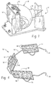
- a first preferred embodiment of the containment structure 50 includes a support member or spring form wire 52 that is contoured or bent to wrap about the periphery of the reflector body adjacent the open end 28 thereof.
- First and second ends 54 of the spring form wire are hook shaped to engage a supporting cage SC that receives the projector lamp assembly.
- bent regions 56 are formed in the wire at predetermined locations that align with the recesses in the reflector body. The bent regions allow individual vent panels 58 to be secured, for example by tack welding, to the wire. Vent panels 58 can be configured to match various cutout recess shapes in the corresponding reflector body.
- vent panels have a series of smally openings 60 (shown here as circular openings) dimensioned to allow sufficient air flow to reach the vent recesses formed in the reflector body.
- the openings are not so large as to impinge on the structural or protective feature required for containment purposes in the event of non-passive failure of the light source.
- An additional contour 62 may be formed in the wire so that, like the hook ends 54, an additional engagement region is defined with the supporting cage that receives the lamp assembly. This provides for precise alignment and positioning of the containment structure relative to the lamp assembly and assures that the vent panels are properly located over the recesses in the reflector body. It will be further appreciated that the vent panels can be disposed on opposite sides of the support wire. Since the wire and panels define a separate containment structure relative to the reflector body and lamp assembly, this arrangement is conducive to recycling of the lamp components. In addition, this containment structure does not interfere with installation and removal of the lamp assembly from the support cage as may be necessary. That is, the lamp assembly may periodically require replacement while the wire/vent containment structure can be used repeatedly.
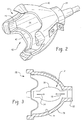
- the containment structure 50' is a hollow square-shaped, cross-sectional screen or basket 70 adapted to be received in a squared end of the reflector body. More particularly, the basket 70 has open first and second ends 72, 74, while the remainder of the basket is preferably circumferentially continuous and dimensioned for receipt within the reflector body open end.
- the peripheral dimension is such that axial insertion toward the necked down region is further precluded since it abuts against an inner diameter of the reflector body at the juncture of the necked region with the enlarged diameter portion of the reflecting surface 26'. In this manner, the basket is easily mounted and/or removed from the lamp assembly for recycling for subsequent use.
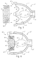
- vent panels 80 are dimensioned for receipt over the recesses 40" in the reflector body.
- the vent panels include openings 82 that may be the same size, or have different sizes, depending on the location of a particular vent panel, i.e., one where additional protection or venting is desired.
- the vent panels are adhesively secured to the reflector body and thus dimensioned to be slightly larger than the recesses without forming a unified or continuous containment structure.
- these screens may be channeled or adopt suitable shapes to direct air flow in a desired pattern through the recesses of the reflector body. Accordingly, various designs and conformations of these vent panels are contemplated by the present invention.
Landscapes
- Engineering & Computer Science (AREA)
- General Engineering & Computer Science (AREA)
- Physics & Mathematics (AREA)
- General Physics & Mathematics (AREA)
- Plasma & Fusion (AREA)
- Non-Portable Lighting Devices Or Systems Thereof (AREA)
- Arrangement Of Elements, Cooling, Sealing, Or The Like Of Lighting Devices (AREA)
- Discharge Lamps And Accessories Thereof (AREA)
- Vessels And Coating Films For Discharge Lamps (AREA)
Abstract
Description
Claims (10)
- A discharge lamp assembly [10] comprising:a discharge light source [12];a reflector [20] operatively associated with the light source for directing light from the light source in a desired manner, the reflector including preformed openings for venting therethrough; anda foraminous [50] containment structure including discrete panels [58] dispose in spaced, overlying relation with the respective reflector openings [60].
- The discharge lamp [10] assembly of claim 1 wherein the discrete panels [58] are interconnected by a structural member.
- The discharge lamp [10] assembly of claim 1 wherein the reflector [20] pre-formed openings are recesses [40] extending axially inward from a first end of the reflector.
- The discharge lamp [10] assembly of claim 1 further comprising a cage [SC] that receives the reflector [20] therein, the containment assembly [50] securing the reflector to the cage.
- A discharge lamp [10] assembly having improved venting and recycling features, the lamp assembly comprising:a discharge light source [12];a reflector [20] operatively associated with the light source for directing light from the light source in a desired manner, the reflector including preformed openings [82] for venting therethrough; anddiscrete panels [58] disposed in spaced, overlying relation with the respective reflector openings and adhesively secured to the reflector.
- The discharge lamp [10] assembly of claim 5 wherein the reflector preformed openings [82] are recesses extending axially inward from a first end of the reflector.
- The discharge lamp [10] assembly of claim 5 further comprising a cage [SC] that receives the reflector [20] therein, the containment assembly [50] securing the reflector to the cage.
- A discharge lamp [10] assembly comprising:a discharge light source [12];a reflector [20] operatively associated with the light source for directing light from the light source in a desired manner, the reflector including preformed openings [82] for venting therethrough; anda basket-like containment [70] assembly dimensioned for receipt within the reflector and circumferentially surrounding the light source.
- The discharge lamp assembly [10] of claim 8 wherein the reflector preformed openings [82] are recesses extending axially inward from a first end of the reflector.
- The discharge lamp assembly [10] of claim 8 further comprising a cage [SC] that receives the reflector therein, the containment assembly [50] securing the reflector to the cage.
Applications Claiming Priority (2)
| Application Number | Priority Date | Filing Date | Title |
|---|---|---|---|
| US09/844,133 US6759794B2 (en) | 2001-04-27 | 2001-04-27 | Discharge lamp with vented reflector |
| US844133 | 2001-04-27 |
Publications (2)
| Publication Number | Publication Date |
|---|---|
| EP1253372A2 true EP1253372A2 (en) | 2002-10-30 |
| EP1253372A3 EP1253372A3 (en) | 2007-05-02 |
Family
ID=25291906
Family Applications (1)
| Application Number | Title | Priority Date | Filing Date |
|---|---|---|---|
| EP02252961A Withdrawn EP1253372A3 (en) | 2001-04-27 | 2002-04-26 | Discharge lamp having improved shield |
Country Status (4)
| Country | Link |
|---|---|
| US (1) | US6759794B2 (en) |
| EP (1) | EP1253372A3 (en) |
| JP (1) | JP4064714B2 (en) |
| TW (1) | TWI221623B (en) |
Families Citing this family (5)
| Publication number | Priority date | Publication date | Assignee | Title |
|---|---|---|---|---|
| JP4656973B2 (en) * | 2005-03-16 | 2011-03-23 | 三菱電機株式会社 | Light source device and projection display device |
| JP4225991B2 (en) * | 2005-07-29 | 2009-02-18 | 三洋電機株式会社 | Projector device |
| JP4243269B2 (en) | 2005-09-09 | 2009-03-25 | 三洋電機株式会社 | Projector device |
| KR102331533B1 (en) * | 2007-04-12 | 2021-11-26 | 가부시키가이샤 니콘 | Discharge lamp |
| JP5903860B2 (en) * | 2011-12-08 | 2016-04-13 | セイコーエプソン株式会社 | LIGHT SOURCE DEVICE, PROJECTOR, AND LIGHT SOURCE DEVICE MANUFACTURING METHOD |
Family Cites Families (12)
| Publication number | Priority date | Publication date | Assignee | Title |
|---|---|---|---|---|
| US3703635A (en) * | 1970-09-08 | 1972-11-21 | E Systems Inc | Zoom light |
| US4053759A (en) * | 1973-04-27 | 1977-10-11 | Optical Radiation Corporation | Lamphouse and module for photographic slide projectors |
| US4925295A (en) * | 1986-03-17 | 1990-05-15 | Casio Computer Co., Ltd. | Projection display apparatus |
| JP3275755B2 (en) * | 1997-01-31 | 2002-04-22 | ウシオ電機株式会社 | Light irradiation unit |
| US5909955A (en) * | 1997-03-10 | 1999-06-08 | Westek Associates | Puck style under cabinet light fixture with improved mounting ring |
| JP3381566B2 (en) * | 1997-07-18 | 2003-03-04 | ウシオ電機株式会社 | Light source unit |
| US6133676A (en) * | 1997-09-10 | 2000-10-17 | Chen; Chun Tsun | Double-enveloped halogen bulb provided with protuberances in the outer surface of the envelope |
| JPH11195322A (en) * | 1997-11-04 | 1999-07-21 | Seiko Epson Corp | Light source device and projection display device |
| WO1999032825A1 (en) * | 1997-12-22 | 1999-07-01 | Koninklijke Philips Electronics N.V. | Unit of electric lamp and reflector |
| JP2000200511A (en) * | 1998-10-30 | 2000-07-18 | Phoenix Denki Kk | Discharge lamp |
| US6306010B1 (en) * | 1999-10-26 | 2001-10-23 | Industrial Gasket, Inc. | Method of forming a hole in a glass reflector |
| DE10032020A1 (en) | 2000-07-01 | 2002-01-10 | Gap Ag Gsm Applikationen Und P | Arrangement for monitoring object position has monitoring control unit that determines reference location area depending on at least one instantaneous position specified by position signal |
-
2001
- 2001-04-27 US US09/844,133 patent/US6759794B2/en not_active Expired - Fee Related
-
2002
- 2002-04-16 TW TW091107770A patent/TWI221623B/en active
- 2002-04-26 JP JP2002125437A patent/JP4064714B2/en not_active Expired - Fee Related
- 2002-04-26 EP EP02252961A patent/EP1253372A3/en not_active Withdrawn
Also Published As
| Publication number | Publication date |
|---|---|
| EP1253372A3 (en) | 2007-05-02 |
| US6759794B2 (en) | 2004-07-06 |
| US20020158558A1 (en) | 2002-10-31 |
| JP4064714B2 (en) | 2008-03-19 |
| JP2002334609A (en) | 2002-11-22 |
| TWI221623B (en) | 2004-10-01 |
Similar Documents
| Publication | Publication Date | Title |
|---|---|---|
| CA1142153A (en) | Lamp having convoluted fluorescent tube encased in screw based envelope | |
| EP1003202B1 (en) | Discharge lamp | |
| CA2266345C (en) | Lamp cartridge | |
| EP0066855B1 (en) | Fluorescent lamp device | |
| USD477891S1 (en) | Ceiling light | |
| WO1997027617A1 (en) | Microwave container screens for electrodeless lamps | |
| JPH0344786B2 (en) | ||
| JP3448022B2 (en) | Plasma lamp structure of microwave lighting device | |
| EP1253372A2 (en) | Discharge lamp having improved shield | |
| WO1997042651A3 (en) | Integrated hid reflector lamp | |
| EP0306269A2 (en) | Double-enveloped electric lamp | |
| EP0104594B1 (en) | Double-enveloped lamp | |
| JP3931529B2 (en) | Light source unit | |
| JP3787105B2 (en) | Outside air blocking device for electrodeless lighting equipment | |
| RU95120321A (en) | DEVICE FOR SOLDERING AND WELDING WITH LIGHT BEAM | |
| JP2544965Y2 (en) | Microwave oven | |
| US5446636A (en) | Light fixture with improved heat dissipation characteristics | |
| JP4625866B2 (en) | Light bulb type fluorescent lamp | |
| JP4375551B2 (en) | Recessed ceiling lighting fixture | |
| MX2014009632A (en) | Discharge lamp. | |
| KR20080081303A (en) | Lighting device and metal vapor discharge lamp | |
| KR100850795B1 (en) | Induction Fluorescent Lamp | |
| KR830002415Y1 (en) | Fluorescent Lamp Device | |
| JPS5819810Y2 (en) | fluorescent lamp device | |
| JPH05217554A (en) | Metal halide lamp |
Legal Events
| Date | Code | Title | Description |
|---|---|---|---|
| PUAI | Public reference made under article 153(3) epc to a published international application that has entered the european phase |
Free format text: ORIGINAL CODE: 0009012 |
|
| AK | Designated contracting states |
Kind code of ref document: A2 Designated state(s): AT BE CH CY DE DK ES FI FR GB GR IE IT LI LU MC NL PT SE TR |
|
| AX | Request for extension of the european patent |
Free format text: AL;LT;LV;MK;RO;SI |
|
| RIC1 | Information provided on ipc code assigned before grant |
Ipc: H01J 61/50 20060101ALI20061214BHEP Ipc: H01J 61/52 20060101ALI20061214BHEP Ipc: G03B 21/20 20060101ALI20061214BHEP Ipc: G03B 21/16 20060101ALI20061214BHEP Ipc: F21V 7/20 20060101AFI20020807BHEP |
|
| PUAL | Search report despatched |
Free format text: ORIGINAL CODE: 0009013 |
|
| AK | Designated contracting states |
Kind code of ref document: A3 Designated state(s): AT BE CH CY DE DK ES FI FR GB GR IE IT LI LU MC NL PT SE TR |
|
| AX | Request for extension of the european patent |
Extension state: AL LT LV MK RO SI |
|
| 17P | Request for examination filed |
Effective date: 20071102 |
|
| AKX | Designation fees paid |
Designated state(s): DE FR GB IT |
|
| 17Q | First examination report despatched |
Effective date: 20081208 |
|
| STAA | Information on the status of an ep patent application or granted ep patent |
Free format text: STATUS: THE APPLICATION IS DEEMED TO BE WITHDRAWN |
|
| 18D | Application deemed to be withdrawn |
Effective date: 20090630 |