EP1253345A2 - A piston and a damping means with a piston - Google Patents
A piston and a damping means with a piston Download PDFInfo
- Publication number
- EP1253345A2 EP1253345A2 EP02007583A EP02007583A EP1253345A2 EP 1253345 A2 EP1253345 A2 EP 1253345A2 EP 02007583 A EP02007583 A EP 02007583A EP 02007583 A EP02007583 A EP 02007583A EP 1253345 A2 EP1253345 A2 EP 1253345A2
- Authority
- EP
- European Patent Office
- Prior art keywords
- seal ring
- piston
- groove
- outside
- chamber
- Prior art date
- Legal status (The legal status is an assumption and is not a legal conclusion. Google has not performed a legal analysis and makes no representation as to the accuracy of the status listed.)
- Granted
Links
Images


Classifications
-
- F—MECHANICAL ENGINEERING; LIGHTING; HEATING; WEAPONS; BLASTING
- F16—ENGINEERING ELEMENTS AND UNITS; GENERAL MEASURES FOR PRODUCING AND MAINTAINING EFFECTIVE FUNCTIONING OF MACHINES OR INSTALLATIONS; THERMAL INSULATION IN GENERAL
- F16F—SPRINGS; SHOCK-ABSORBERS; MEANS FOR DAMPING VIBRATION
- F16F9/00—Springs, vibration-dampers, shock-absorbers, or similarly-constructed movement-dampers using a fluid or the equivalent as damping medium
- F16F9/32—Details
- F16F9/3207—Constructional features
-
- B—PERFORMING OPERATIONS; TRANSPORTING
- B60—VEHICLES IN GENERAL
- B60G—VEHICLE SUSPENSION ARRANGEMENTS
- B60G17/00—Resilient suspensions having means for adjusting the spring or vibration-damper characteristics, for regulating the distance between a supporting surface and a sprung part of vehicle or for locking suspension during use to meet varying vehicular or surface conditions, e.g. due to speed or load
- B60G17/02—Spring characteristics, e.g. mechanical springs and mechanical adjusting means
- B60G17/04—Spring characteristics, e.g. mechanical springs and mechanical adjusting means fluid spring characteristics
- B60G17/0408—Spring characteristics, e.g. mechanical springs and mechanical adjusting means fluid spring characteristics details, e.g. antifreeze for suspension fluid, pumps, retarding means per se
-
- B—PERFORMING OPERATIONS; TRANSPORTING
- B60—VEHICLES IN GENERAL
- B60G—VEHICLE SUSPENSION ARRANGEMENTS
- B60G17/00—Resilient suspensions having means for adjusting the spring or vibration-damper characteristics, for regulating the distance between a supporting surface and a sprung part of vehicle or for locking suspension during use to meet varying vehicular or surface conditions, e.g. due to speed or load
- B60G17/02—Spring characteristics, e.g. mechanical springs and mechanical adjusting means
- B60G17/04—Spring characteristics, e.g. mechanical springs and mechanical adjusting means fluid spring characteristics
- B60G17/056—Regulating distributors or valves for hydropneumatic systems
-
- B—PERFORMING OPERATIONS; TRANSPORTING
- B60—VEHICLES IN GENERAL
- B60G—VEHICLE SUSPENSION ARRANGEMENTS
- B60G21/00—Interconnection systems for two or more resiliently-suspended wheels, e.g. for stabilising a vehicle body with respect to acceleration, deceleration or centrifugal forces
- B60G21/02—Interconnection systems for two or more resiliently-suspended wheels, e.g. for stabilising a vehicle body with respect to acceleration, deceleration or centrifugal forces permanently interconnected
- B60G21/06—Interconnection systems for two or more resiliently-suspended wheels, e.g. for stabilising a vehicle body with respect to acceleration, deceleration or centrifugal forces permanently interconnected fluid
-
- F—MECHANICAL ENGINEERING; LIGHTING; HEATING; WEAPONS; BLASTING
- F15—FLUID-PRESSURE ACTUATORS; HYDRAULICS OR PNEUMATICS IN GENERAL
- F15B—SYSTEMS ACTING BY MEANS OF FLUIDS IN GENERAL; FLUID-PRESSURE ACTUATORS, e.g. SERVOMOTORS; DETAILS OF FLUID-PRESSURE SYSTEMS, NOT OTHERWISE PROVIDED FOR
- F15B15/00—Fluid-actuated devices for displacing a member from one position to another; Gearing associated therewith
- F15B15/08—Characterised by the construction of the motor unit
- F15B15/14—Characterised by the construction of the motor unit of the straight-cylinder type
- F15B15/1423—Component parts; Constructional details
- F15B15/1447—Pistons; Piston to piston rod assemblies
- F15B15/1452—Piston sealings
-
- F—MECHANICAL ENGINEERING; LIGHTING; HEATING; WEAPONS; BLASTING
- F16—ENGINEERING ELEMENTS AND UNITS; GENERAL MEASURES FOR PRODUCING AND MAINTAINING EFFECTIVE FUNCTIONING OF MACHINES OR INSTALLATIONS; THERMAL INSULATION IN GENERAL
- F16F—SPRINGS; SHOCK-ABSORBERS; MEANS FOR DAMPING VIBRATION
- F16F9/00—Springs, vibration-dampers, shock-absorbers, or similarly-constructed movement-dampers using a fluid or the equivalent as damping medium
- F16F9/32—Details
- F16F9/36—Special sealings, including sealings or guides for piston-rods
- F16F9/365—Special sealings, including sealings or guides for piston-rods the sealing arrangement having a pressurised chamber separated from the damping medium
-
- B—PERFORMING OPERATIONS; TRANSPORTING
- B60—VEHICLES IN GENERAL
- B60G—VEHICLE SUSPENSION ARRANGEMENTS
- B60G2202/00—Indexing codes relating to the type of spring, damper or actuator
- B60G2202/10—Type of spring
- B60G2202/15—Fluid spring
- B60G2202/154—Fluid spring with an accumulator
-
- B—PERFORMING OPERATIONS; TRANSPORTING
- B60—VEHICLES IN GENERAL
- B60G—VEHICLE SUSPENSION ARRANGEMENTS
- B60G2204/00—Indexing codes related to suspensions per se or to auxiliary parts
- B60G2204/80—Interactive suspensions; arrangement affecting more than one suspension unit
-
- B—PERFORMING OPERATIONS; TRANSPORTING
- B60—VEHICLES IN GENERAL
- B60G—VEHICLE SUSPENSION ARRANGEMENTS
- B60G2204/00—Indexing codes related to suspensions per se or to auxiliary parts
- B60G2204/80—Interactive suspensions; arrangement affecting more than one suspension unit
- B60G2204/83—Type of interconnection
- B60G2204/8304—Type of interconnection using a fluid
-
- B—PERFORMING OPERATIONS; TRANSPORTING
- B60—VEHICLES IN GENERAL
- B60G—VEHICLE SUSPENSION ARRANGEMENTS
- B60G2204/00—Indexing codes related to suspensions per se or to auxiliary parts
- B60G2204/80—Interactive suspensions; arrangement affecting more than one suspension unit
- B60G2204/83—Type of interconnection
- B60G2204/8306—Permanent; Continuous
-
- B—PERFORMING OPERATIONS; TRANSPORTING
- B60—VEHICLES IN GENERAL
- B60G—VEHICLE SUSPENSION ARRANGEMENTS
- B60G2206/00—Indexing codes related to the manufacturing of suspensions: constructional features, the materials used, procedures or tools
- B60G2206/01—Constructional features of suspension elements, e.g. arms, dampers, springs
- B60G2206/40—Constructional features of dampers and/or springs
- B60G2206/42—Springs
- B60G2206/422—Accumulators for hydropneumatic springs
Definitions
- This invention relates to a piston for inserting into a cylinder, in particular into a cylinder of a hydraulic damping means, with a piston body having an annular groove at its outside surface, and an elastic seal ring fitted into said groove, and to a damping means, in particular a hydraulic damping means, with a piston inserted into a cylinder bore of a cylinder tube for free sliding and for dividing said cylinder bore into first and second chambers, wherein said piston comprises a piston body having an annular groove at its outside surface, and an elastic seal ring fitted into said groove.
- damping systems for restricting rolling and pitching of the vehicle body by damping impact forces coming from the road surface through the wheels to the vehicle body while the vehicle is running on the road.
- a damping system comprises paired right and left hydraulic dampers installed between the vehicle body and members on the wheel side, and a hydraulic cylinder that interconnects the dampers.
- the cylinder is provided with a cylinder tube supported on the vehicle body, and a piston inserted for free sliding within the bore in the cylinder tube and for dividing the cylinder bore into first and second chambers.
- the piston comprises a piston body with its outside cylindrical surface formed with an annular groove centered on its axis and an elastic seal ring fitted into the groove as centered on the axis.
- the inside circumferential surface of the seal ring is in pressing contact with the bottom surface of the groove while its outside circumferential surface is in pressing contact with the inside cylindrical surface of the cylinder bore, so that the area between the first and second chambers is sealed up.
- the cylinder is made to be in communication with respective dampers through hydraulic pipes.
- the work of assembling the cylinder includes the step of fitting the seal ring into the groove formed in the piston body.
- the seal ring is radially expanded so that its (inside) diameter increases by its elastic deformation, and fitted over one end, with respect to the axial direction, of the piston body.
- the seal ring is slid along the outside cylindrical surface of the piston body in the axial direction, so that the seal ring falls and fits into the groove.
- the seal ring contracts by its own elasticity to its original shape in the groove, the (inside) diameter of the seal ring decreases and the inside diameter surface comes into pressing contact with the groove bottom surface.
- the seal ring fitting step is completed.
- the diametral dimension of the groove bottom is designed so that the bottom and the inside circumferential surface of the seal ring are in pressing contact with each other, and the depth of the groove is designed to be enough for containing the seal ring.
- the piston body is made with an outside diameter that is considerably greater than the inside diameter of the seal ring.
- the first problem is that, when the seal ring is fitted into the groove, it cannot return fully to its original shape by its own elasticity only, the press-contact force of the internal surface of the seal ring against the groove bottom surface becomes insufficient, and the sealing effect with the seal ring might be lowered.
- the second problem is that, after the seal ring contracts toward its original shape in the groove, its outside diameter is too great and, when the piston is to be inserted into the cylinder bore in the cylinder tube, the inserting work becomes hard as the outer edge of the seal ring is caught with the edge at the opening of the cylinder bore.
- This invention is made in view of the above situation with an objective to improve a piston as mentioned above so as to facilitate the cylinder assembly work by making it easy to insert the seal ring into the groove on the piston body and to insert the piston into the cylinder bore.
- a piston for inserting into a cylinder, in particular into a cylinder of a hydraulic damping means, with a piston body having an annular groove at its outside surface, and an elastic seal ring fitted into said groove, wherein said outside surface of said piston body comprises two different outside diameters on respective sides of said annular groove.
- said outside diameter of said outside surface located on an outer side of said piston body on one side of said annular groove is made smaller than said outside diameter of said outside surface located on an inner side of said piston body on another side of said annular groove.
- said outside diameter of said outside surface located on an outer side of said piston body is gradually decreased from a groove side toward an end in an axial direction of said piston body.
- said elastic seal ring is urged radially outward through another seal ring interposed between a bottom surface of said annular groove and said elastic seal ring.
- said piston body comprises a second groove provided adjacent to said annular groove and on a side of said annular groove with said greater outside diameter of said two different outside diameters.
- said outside surface of said piston body comprises two equal outside diameters on both sides of said second groove, wherein an elastic O-ring is fitted into said second groove.
- said different rings are made of different materials.
- a damping means in particular a hydraulic damping means, with a piston inserted into a cylinder bore of a cylinder tube for free sliding and for dividing said cylinder bore into first and second chambers, wherein said piston comprises a piston body having an annular groove at its outside surface, and an elastic seal ring fitted into said groove, wherein said outside surface of said piston body comprises two different outside diameters on respective sides of said groove.
- a maximum pressure of fluid produced in said first chamber is greater than that produced in said second chamber, and said first chamber is located on a side of said outside diameter with a smaller value.
- said first chamber is filled with a fluid or an oil
- said second chamber is filled with a fluid or a gas
- the above vehicle is also provided with a hydraulic damping system 3 to restrict the vehicle body 1 from pitching or rolling by damping shocks that tend to be transmitted from the road surface through the wheels to the vehicle body 1 while the vehicle is running.
- the damping system 3 includes hydraulic dampers 4, 4 provided respectively in the suspensions 2, 2 and a hydraulic cylinder 6 which makes hydraulic communication with the dampers 4, 4 through hydraulic tubes 5, 5.
- Each damper 4 is interposed between the vehicle body 1 and a wheel-side-located member 7.
- the cylinder 6 includes a cylinder tube 10 supported on the vehicle body 1, and a piston 13 inserted for free sliding in the direction of its axis 12 in the cylinder bore 11 formed in the cylinder tube 10.
- the cylinder bore 11 is divided into the first and second chambers 14 and 15 by the piston 13.
- the axis 12 extends to be nearly vertical.
- the cylinder 6 also includes another piston 17 inserted for free sliding in the first chamber 14 in its axial direction.
- the another piston 17 is fixed to the piston 13 to slide together as a single body.
- the first chamber 14 is divided into two chambers 18, 19 with the another piston 17.
- one chamber 18 is made to communicate with the hydraulic chamber of one damper 4 through the hydraulic tube 5 while the other chamber 19 to that of the other damper 4 through the other hydraulic tube 5.
- the another piston 17 is provided with a narrow passage 20 for intercommunicating both chambers 18, 19.
- each damper 4 and the first chamber 14 of the cylinder 6 are filled with a fluid 21 or an oil 21a.
- the second chamber 15 of the cylinder 6 is filled with a fluid 21 or a gas 21b (nitrogen gas).
- a spring 22 is provided in the second chamber 15 to urge the piston 13 toward the first chamber 14.
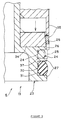
- the piston 13 includes a piston body 23 located on the axis 12.
- the outside surface of the piston body 23 is formed with an annular groove 24 about the axis 12.
- a seal ring 25 made of an elastic material (Teflon, in trade name) is fitted into the groove 24 about the axis 12, and mounted to the piston body 13.
- the seal ring 25 is in pressing contact with the bottom surface 24a of the groove 24 and surfaces 24b, 24b of the groove 24 opposing each other in the axial direction.
- the seal ring 25 is in a state slightly elongated elastically in its longitudinal direction.
- one part located on one (upper) side of the groove 24 in the axial direction is assumed to be the first outside cylindrical surface 26 while the other part (on the other, lower side) to be the second outside cylindrical surface 27.
- the second outside cylindrical surface 27 is formed with another annular groove 30 about the axis 12.
- An elastic O-ring 31 made of rubber is fitted into the another groove 30 about the axis 12, so as to be attached to the piston 13.
- the outer circumferential surfaces of the seal ring 25 and the O-ring 31 are made to come into pressing contact with the inside circumferential surface of the cylinder bore 11 to seal up the part between the first chamber 14 and the second chamber 15.
- the seal ring 25 is made higher (harder) in the modulus of elasticity than the rubber-made O-ring 31. Accordingly, the piston 13 moves in swift response to the change in the pressure of the fluid 21 present on the first chamber 14 side.
- a truncated cone-shaped jig 34 is placed coaxially with the axis 12, with its larger diameter side being on one axial direction end face of the piston body 23.
- the seal ring 25 is fitted over the smaller diameter side of the jig 34 (shown with solid lines in FIG. 3), moved toward the larger diameter side of the jig 34 using a press motion member 35, and farther moved toward the groove 24. Then the seal ring 25 easily falls and fits into the groove 24 (shown with phantom lines in FIG. 3).
- the outside diameter D1 of the first outside cylindrical surface 26 is made smaller than that D2 of the second outside cylindrical surface 27.
- the work of fitting the seal ring 25 into the groove 24 of the piston body 23 as a step of the work of assembling the cylinder 6 may be done as follows: First, the seal ring 25 is deformed elastically to increase its inside diameter, fitted over the first outside cylindrical surface 26, out of the outside cylindrical surface, of the piston body 23, and fitted into the groove 24.
- the seal ring 25 is passed over the first outside cylindrical surface 26 of the smaller diameter D1 to fit into the groove 24. That is, the insertion work is facilitated as the amount of expanding the inside diameter of the seal ring 25 is reduced according to the smaller dimension of the outside diameter D1.
- the outside diameter of the seal ring 25 after returning to its original shape in the groove 24 is prevented from increasing excessively. Therefore, the outside circumferential edge of the seal ring 25 is prevented from being caught with the opening edge of the cylinder bore 11 when the piston 13 is inserted into the cylinder bore 11 of the cylinder tube 10. As a result, the work of fitting the piston 13 into the cylinder bore 11 is facilitated.
- the length of the first outside cylindrical surface 26 in the axial direction is set shorter than that of the second outside cylindrical surface 27.
- the distance of sliding the seal ring 25 over the outside cylindrical surface of the piston body 23 from its one end toward the groove 24 may be shortened when inserting the seal ring 25, to further facilitate the insertion work.
- the outside diameter D1 of the first outside cylindrical surface 26 is made to be a maximum on the groove 24 side and to decrease gradually toward the end away from the groove 24 in the axial direction of the piston body 23 (toward the first chamber 14).
- the maximum hydraulic pressure of the fluid 21 produced in the first chamber 14 is greater than that in the second chamber 15.
- the first chamber 14 is located on the side of the first outside cylindrical surface 26 in the axial direction of the piston 13 while the second chamber 15 is located on the side of the second outside cylindrical surface 27.
- the seal ring 25 fitted into the groove 24 is pressed with high pressure fluid 21 from the side of the first chamber 14 toward the second chamber 15 and pressed against the one 24b, on the second chamber 15 side, of the axially opposing surfaces 24b, 24b with a greater force.
- the outside diameter D1 of the first outside cylindrical surface 26 is made smaller than the outside diameter D2 of the second outside cylindrical surface 27, and accordingly the area of the opposing surface 24b on the second chamber 15 side is held unchanged at a larger value.
- the seal ring 25 is pressed with the high pressure of the fluid 21 on the first chamber 14 side against the opposing surface 24b on the second chamber 15 side.
- the area of this opposing surface 24b is greater, pressure per unit area onto the opposing surface 24b is accordingly held low, which is advantageous for the service life of the seal ring 25.
- another elastic seal ring 37 is placed between the bottom surface 24a of the groove 24 and the seal ring 25 about the axis 12, so that the another seal ring 37 urges the seal ring 25 radially outward.
- the another seal ring 37 is made of a material such as rubber which is lower in modulus of elasticity than the material of the seal ring 25, it is possible to increase the amount of deformation of the another seal ring 37, so that it can be fitted easily into the groove 24.
- the seal ring 25 is made of a material of a relatively great modulus of elasticity such as Teflon (trade name)
- Teflon trade name
- both of the seal rings 25 and 37 can be fitted easily into the groove 24 and the sealing effect with the seal rings 25 and 37 is held unchanged in favorable state.
- the spring 22, the another groove 30, and the O-ring 31 may be omitted.
- This invention provides effects as described below.
- a constitution of a piston in a cylinder comprising a cylinder tube and the piston inserted for free sliding in the axial direction into the cylinder bore in the cylinder tube and for dividing the cylinder bore into first and second chambers, with the piston comprising a piston body with its outside cylindrical surface having an annular groove centered on its axis and an elastic seal ring fitted as centered on the above axis into the groove.
- one part of the outside cylindrical surface of the piston body that is located on one side in the axial direction of the groove is regarded as the first outside cylindrical surface and the other part of the outside cylindrical surface located on the other side of the groove is regarded as the second outside cylindrical surface, and the outside diameter of the first outside cylindrical surface is made smaller than that of the second outside cylindrical surface.
- the seal ring is to be fitted into the groove as a step of assembling the cylinder, first the seal ring is elastically deformed to increase its inside diameter, fitted over the first outside cylindrical surface, out of the outside cylindrical surface, of the piston body, and fitted into the groove.
- the seal ring is passed over the first outside cylindrical surface having a smaller diameter and fitted into the groove. According to the smaller diameter, the amount of expanding the inside diameter of the seal ring can remain small, so that the seal ring can be fitted easily.
- the plastic deformation in the seal ring is restricted from occurring according to the extent of reduction in the amount of expanding the inside diameter of the seal ring.
- the seal ring when the seal ring is fitted into the groove, the seal ring returns to its original shape by its own elasticity to contact well the groove bottom surface and keeps the sealing effect with the seal ring in favorable state.
- the outside diameter of the seal ring is prevented from becoming too great.
- the outer circumferential part of the seal ring is prevented from being caught with the opening edge of the cylinder bore. This facilitates the work of inserting the piston into the cylinder bore.
- the outside diameter of the first outside cylindrical surface is gradually decreased from the groove side toward the end in the axial direction of the piston body.
- the seal ring when the seal ring is to be fitted over the first outside cylindrical surface as the first step of fitting in the seal ring, the seal ring is to be fitted over the smaller diameter portion of the first outside cylindrical surface, so that the work of fitting in the seal ring can be done easily.
- the work of fitting the seal ring into the groove may be done easily.
- the maximum hydraulic pressure of fluid produced in the first chamber is greater than that produced in the second chamber, and the first chamber is located on the side of the first outside cylindrical surface in the axial direction of the piston while the second chamber is located on the side of the second outside cylindrical surface.
- the seal ring fitted into the groove is pressed toward the second chamber with the pressure of the higher pressure fluid from the first chamber side, and so the seal ring tends to be pressed with a larger force against the opposing surface located on the second chamber side, out of axially opposing surfaces of the groove.
- the outside diameter of the first outside cylindrical surface is made smaller than that of the second outside cylindrical surface, and accordingly the area of the opposing surface on the first chamber side is held unchanged to be greater than the area of the opposing surface on the second chamber side.
- the seal ring tends to contact the opposing surface located on the second chamber side with a greater force.
- this opposing surface area is greater, the pressure per unit area of the opposing surface is held accordingly smaller, which is advantageous for the service life of the seal ring.
- the seal ring is urged radially outward with another seal ring interposed, as centered on the axis, between the bottom surface of the groove and the seal ring.
- the another seal ring is made of a material such as rubber which is lower in modulus of elasticity than the material of the seal ring, it is possible to increase the amount of deformation of the another seal ring, so that it can be fitted easily into the groove.
- the seal ring is made of a material of a relatively great modulus of elasticity such as Teflon (trade name)
- Teflon trade name
Abstract
Description
- This invention relates to a piston for inserting into a cylinder, in particular into a cylinder of a hydraulic damping means, with a piston body having an annular groove at its outside surface, and an elastic seal ring fitted into said groove, and to a damping means, in particular a hydraulic damping means, with a piston inserted into a cylinder bore of a cylinder tube for free sliding and for dividing said cylinder bore into first and second chambers, wherein said piston comprises a piston body having an annular groove at its outside surface, and an elastic seal ring fitted into said groove.
- One of conventional automobiles is disclosed in a Japanese Unexamined Patent Publication No. Sho 55-5114.
- According to the above publication, automobiles are provided with damping systems for restricting rolling and pitching of the vehicle body by damping impact forces coming from the road surface through the wheels to the vehicle body while the vehicle is running on the road. Such a damping system comprises paired right and left hydraulic dampers installed between the vehicle body and members on the wheel side, and a hydraulic cylinder that interconnects the dampers.
- The cylinder is provided with a cylinder tube supported on the vehicle body, and a piston inserted for free sliding within the bore in the cylinder tube and for dividing the cylinder bore into first and second chambers. The piston comprises a piston body with its outside cylindrical surface formed with an annular groove centered on its axis and an elastic seal ring fitted into the groove as centered on the axis. Here, the inside circumferential surface of the seal ring is in pressing contact with the bottom surface of the groove while its outside circumferential surface is in pressing contact with the inside cylindrical surface of the cylinder bore, so that the area between the first and second chambers is sealed up. The cylinder is made to be in communication with respective dampers through hydraulic pipes.
- When each damper performs extension and contraction motions as the wheel moves up and down while the vehicle runs over a road surface, the piston in the cylinder slides in interlocked motion in its axial direction to restrict the extension and contraction motions. In this way the vehicle body is restricted from rolling and pitching.
- Here, the work of assembling the cylinder includes the step of fitting the seal ring into the groove formed in the piston body. First, the seal ring is radially expanded so that its (inside) diameter increases by its elastic deformation, and fitted over one end, with respect to the axial direction, of the piston body. Next, the seal ring is slid along the outside cylindrical surface of the piston body in the axial direction, so that the seal ring falls and fits into the groove. Thus, the seal ring contracts by its own elasticity to its original shape in the groove, the (inside) diameter of the seal ring decreases and the inside diameter surface comes into pressing contact with the groove bottom surface. Thus, the seal ring fitting step is completed.
- The diametral dimension of the groove bottom is designed so that the bottom and the inside circumferential surface of the seal ring are in pressing contact with each other, and the depth of the groove is designed to be enough for containing the seal ring. As a result, the piston body is made with an outside diameter that is considerably greater than the inside diameter of the seal ring.
- Therefore, partial plastic deformation might occur in part of the seal ring when the seal ring is elastically expanded to fit over the one end of the piston body before fitting the seal ring into the groove.
- If the plastic deformation occurs, the first problem is that, when the seal ring is fitted into the groove, it cannot return fully to its original shape by its own elasticity only, the press-contact force of the internal surface of the seal ring against the groove bottom surface becomes insufficient, and the sealing effect with the seal ring might be lowered.
- The second problem is that, after the seal ring contracts toward its original shape in the groove, its outside diameter is too great and, when the piston is to be inserted into the cylinder bore in the cylinder tube, the inserting work becomes hard as the outer edge of the seal ring is caught with the edge at the opening of the cylinder bore.
- This invention is made in view of the above situation with an objective to improve a piston as mentioned above so as to facilitate the cylinder assembly work by making it easy to insert the seal ring into the groove on the piston body and to insert the piston into the cylinder bore.
- It is a further objective of the present invention to improve a damping means as mentioned above so as to facilitate the work of assembling the piston to the cylinder of the damping means.
- According to the invention, the objective is solved by a piston for inserting into a cylinder, in particular into a cylinder of a hydraulic damping means, with a piston body having an annular groove at its outside surface, and an elastic seal ring fitted into said groove, wherein said outside surface of said piston body comprises two different outside diameters on respective sides of said annular groove.
- Here, it is an advantage to prevent an overexpanding of the seal ring and thus, to maintain a good sealing effect with the seal ring.
- According to a preferred embodiment, said outside diameter of said outside surface located on an outer side of said piston body on one side of said annular groove is made smaller than said outside diameter of said outside surface located on an inner side of said piston body on another side of said annular groove.
- According to another preferred embodiment, said outside diameter of said outside surface located on an outer side of said piston body is gradually decreased from a groove side toward an end in an axial direction of said piston body.
- According to still another preferred embodiment, said elastic seal ring is urged radially outward through another seal ring interposed between a bottom surface of said annular groove and said elastic seal ring.
- According to a further preferred embodiment, said piston body comprises a second groove provided adjacent to said annular groove and on a side of said annular groove with said greater outside diameter of said two different outside diameters.
- According to a further preferred embodiment, said outside surface of said piston body comprises two equal outside diameters on both sides of said second groove, wherein an elastic O-ring is fitted into said second groove.
- According to a further preferred embodiment, said different rings are made of different materials.
- According to the damping means of the invention as mentioned above, the above-mentioned objective is solved by a damping means, in particular a hydraulic damping means, with a piston inserted into a cylinder bore of a cylinder tube for free sliding and for dividing said cylinder bore into first and second chambers, wherein said piston comprises a piston body having an annular groove at its outside surface, and an elastic seal ring fitted into said groove, wherein said outside surface of said piston body comprises two different outside diameters on respective sides of said groove.
- According to a preferred embodiment, a maximum pressure of fluid produced in said first chamber is greater than that produced in said second chamber, and said first chamber is located on a side of said outside diameter with a smaller value.
- According to still another preferred embodiment, said first chamber is filled with a fluid or an oil, and said second chamber is filled with a fluid or a gas.
- Other preferred embodiments of the present invention are laid down in further dependent claims.
- In the following, the present invention is explained in greater detail with respect to several embodiments thereof in conjunction with the accompanying drawings, wherein:
- FIG. 1
- is an enlarged cross-sectional view of the portion encircled with a phantom line in FIG. 2;
- FIG. 2
- is a schematic, overall cross-sectional view of a damping system; and
- FIG. 3
- shows the process of fitting the seal ring into the groove.
- The above vehicle is also provided with a hydraulic damping system 3 to restrict the vehicle body 1 from pitching or rolling by damping shocks that tend to be transmitted from the road surface through the wheels to the vehicle body 1 while the vehicle is running.
- The damping system 3 includes hydraulic dampers 4, 4 provided respectively in the
suspensions hydraulic cylinder 6 which makes hydraulic communication with the dampers 4, 4 through hydraulic tubes 5, 5. Each damper 4 is interposed between the vehicle body 1 and a wheel-side-locatedmember 7. - The
cylinder 6 includes acylinder tube 10 supported on the vehicle body 1, and apiston 13 inserted for free sliding in the direction of itsaxis 12 in thecylinder bore 11 formed in thecylinder tube 10. Thecylinder bore 11 is divided into the first andsecond chambers piston 13. Here, theaxis 12 extends to be nearly vertical. - The
cylinder 6 also includes anotherpiston 17 inserted for free sliding in thefirst chamber 14 in its axial direction. Theanother piston 17 is fixed to thepiston 13 to slide together as a single body. Thefirst chamber 14 is divided into twochambers 18, 19 with theanother piston 17. Of the two chambers, onechamber 18 is made to communicate with the hydraulic chamber of one damper 4 through the hydraulic tube 5 while the other chamber 19 to that of the other damper 4 through the other hydraulic tube 5. Theanother piston 17 is provided with anarrow passage 20 for intercommunicating bothchambers 18, 19. - The hydraulic chamber of each damper 4 and the
first chamber 14 of thecylinder 6 are filled with a fluid 21 or anoil 21a. Thesecond chamber 15 of thecylinder 6 is filled with a fluid 21 or a gas 21b (nitrogen gas). Aspring 22 is provided in thesecond chamber 15 to urge thepiston 13 toward thefirst chamber 14. - As shown in FIGs. 1 and 2, the
piston 13 includes apiston body 23 located on theaxis 12. The outside surface of thepiston body 23 is formed with anannular groove 24 about theaxis 12. Aseal ring 25 made of an elastic material (Teflon, in trade name) is fitted into thegroove 24 about theaxis 12, and mounted to thepiston body 13. Here, it is arranged that theseal ring 25 is in pressing contact with thebottom surface 24a of thegroove 24 andsurfaces groove 24 opposing each other in the axial direction. Theseal ring 25 is in a state slightly elongated elastically in its longitudinal direction. - Of the outside surface of the
piston body 23, one part located on one (upper) side of thegroove 24 in the axial direction is assumed to be the first outsidecylindrical surface 26 while the other part (on the other, lower side) to be the second outsidecylindrical surface 27. - The second outside
cylindrical surface 27 is formed with anotherannular groove 30 about theaxis 12. An elastic O-ring 31 made of rubber is fitted into theanother groove 30 about theaxis 12, so as to be attached to thepiston 13. - The outer circumferential surfaces of the
seal ring 25 and the O-ring 31 are made to come into pressing contact with the inside circumferential surface of the cylinder bore 11 to seal up the part between thefirst chamber 14 and thesecond chamber 15. Theseal ring 25 is made higher (harder) in the modulus of elasticity than the rubber-made O-ring 31. Accordingly, thepiston 13 moves in swift response to the change in the pressure of the fluid 21 present on thefirst chamber 14 side. - In case the hydraulic chamber of one of the two dampers 4, 4 is extended and the hydraulic chamber of the other damper 4 is contracted due to impact forces given from the road surface to the wheels, rapid change in the difference between lengths of the dampers 4 is prevented from occurring as the
oil 21a passes through thenarrow passage 20, so that the vehicle body 1 is restricted from rolling. In case both of the dampers 4, 4 are made to contract simultaneously due to the impact forces, thepiston 13 moves toward thesecond chamber 15 side against the pressure of the gas 21b in thesecond chamber 15, so that the impact forces are damped and the vehicle body 1 is restricted from pitching. - During the work of assembling the
cylinder 6, first as shown in FIG. 3, in preparation for fitting theseal ring 25 into thegroove 24 of thepiston body 23, a truncated cone-shapedjig 34 is placed coaxially with theaxis 12, with its larger diameter side being on one axial direction end face of thepiston body 23. Next, theseal ring 25 is fitted over the smaller diameter side of the jig 34 (shown with solid lines in FIG. 3), moved toward the larger diameter side of thejig 34 using apress motion member 35, and farther moved toward thegroove 24. Then theseal ring 25 easily falls and fits into the groove 24 (shown with phantom lines in FIG. 3). - In FIG. 1, the outside diameter D1 of the first outside
cylindrical surface 26 is made smaller than that D2 of the second outsidecylindrical surface 27. - Therefore, the work of fitting the
seal ring 25 into thegroove 24 of thepiston body 23 as a step of the work of assembling thecylinder 6 may be done as follows: First, theseal ring 25 is deformed elastically to increase its inside diameter, fitted over the first outsidecylindrical surface 26, out of the outside cylindrical surface, of thepiston body 23, and fitted into thegroove 24. - In this way, the
seal ring 25 is passed over the first outsidecylindrical surface 26 of the smaller diameter D1 to fit into thegroove 24. That is, the insertion work is facilitated as the amount of expanding the inside diameter of theseal ring 25 is reduced according to the smaller dimension of the outside diameter D1. - Also according to the reduction in the amount of expanding the inside diameter of the
seal ring 25 as described above, plastic deformation of theseal ring 25 is restricted from occurring. - First, therefore, when the
seal ring 25 is fitted into thegroove 24, theseal ring 25 returns to its original shape by its own elasticity, comes into contact with thebottom surface 24a of thegroove 24 with a sufficient force, and the sealing effect with theseal ring 25 is maintained satisfactorily. - Second, the outside diameter of the
seal ring 25 after returning to its original shape in thegroove 24 is prevented from increasing excessively. Therefore, the outside circumferential edge of theseal ring 25 is prevented from being caught with the opening edge of the cylinder bore 11 when thepiston 13 is inserted into the cylinder bore 11 of thecylinder tube 10. As a result, the work of fitting thepiston 13 into the cylinder bore 11 is facilitated. - In the above arrangement, the length of the first outside
cylindrical surface 26 in the axial direction is set shorter than that of the second outsidecylindrical surface 27. - Therefore, the distance of sliding the
seal ring 25 over the outside cylindrical surface of thepiston body 23 from its one end toward thegroove 24 may be shortened when inserting theseal ring 25, to further facilitate the insertion work. - As shown with phantom lines in FIG. 1, it may be alternatively arranged that the outside diameter D1 of the first outside
cylindrical surface 26 is made to be a maximum on thegroove 24 side and to decrease gradually toward the end away from thegroove 24 in the axial direction of the piston body 23 (toward the first chamber 14). - With the above arrangement, as the first step of fitting the
seal ring 25 over the first outsidecylindrical surface 26, first theseal ring 25 has only to be fitted around the small diameter portion of the first outsidecylindrical surface 26, so that the work is made easy. - The work of inserting the
seal ring 25 into thegroove 24 is made easier accordingly. - As described before, since the
piston 13 is urged by thespring 22 toward thefirst chamber 14, the maximum hydraulic pressure of the fluid 21 produced in thefirst chamber 14 is greater than that in thesecond chamber 15. Here, thefirst chamber 14 is located on the side of the first outsidecylindrical surface 26 in the axial direction of thepiston 13 while thesecond chamber 15 is located on the side of the second outsidecylindrical surface 27. - The
seal ring 25 fitted into thegroove 24 is pressed with high pressure fluid 21 from the side of thefirst chamber 14 toward thesecond chamber 15 and pressed against the one 24b, on thesecond chamber 15 side, of the axially opposingsurfaces - However, as described above, the outside diameter D1 of the first outside
cylindrical surface 26 is made smaller than the outside diameter D2 of the second outsidecylindrical surface 27, and accordingly the area of the opposingsurface 24b on thesecond chamber 15 side is held unchanged at a larger value. - Therefore, the
seal ring 25 is pressed with the high pressure of the fluid 21 on thefirst chamber 14 side against the opposingsurface 24b on thesecond chamber 15 side. However, since the area of this opposingsurface 24b is greater, pressure per unit area onto the opposingsurface 24b is accordingly held low, which is advantageous for the service life of theseal ring 25. - As shown with a dash-and-dotted line in FIGs. 1 and 3, another
elastic seal ring 37 is placed between thebottom surface 24a of thegroove 24 and theseal ring 25 about theaxis 12, so that the anotherseal ring 37 urges theseal ring 25 radially outward. - Therefore, when the another
seal ring 37 is made of a material such as rubber which is lower in modulus of elasticity than the material of theseal ring 25, it is possible to increase the amount of deformation of the anotherseal ring 37, so that it can be fitted easily into thegroove 24. Even when theseal ring 25 is made of a material of a relatively great modulus of elasticity such as Teflon (trade name), the inside diameter of theseal ring 25 may be increased because of the presence of the anotherseal ring 37, so that theseal ring 25 may be fitted into thegroove 24 more easily without causing plastic deformation of theseal ring 25. - Therefore, both of the seal rings 25 and 37 can be fitted easily into the
groove 24 and the sealing effect with the seal rings 25 and 37 is held unchanged in favorable state. - Incidentally in the example shown above in the drawings, the
spring 22, the anothergroove 30, and the O-ring 31 may be omitted. - This invention provides effects as described below.
- There is shown a constitution of a piston in a cylinder comprising a cylinder tube and the piston inserted for free sliding in the axial direction into the cylinder bore in the cylinder tube and for dividing the cylinder bore into first and second chambers, with the piston comprising a piston body with its outside cylindrical surface having an annular groove centered on its axis and an elastic seal ring fitted as centered on the above axis into the groove.
- In the above cylinder, one part of the outside cylindrical surface of the piston body that is located on one side in the axial direction of the groove is regarded as the first outside cylindrical surface and the other part of the outside cylindrical surface located on the other side of the groove is regarded as the second outside cylindrical surface, and the outside diameter of the first outside cylindrical surface is made smaller than that of the second outside cylindrical surface.
- Therefore, in case the seal ring is to be fitted into the groove as a step of assembling the cylinder, first the seal ring is elastically deformed to increase its inside diameter, fitted over the first outside cylindrical surface, out of the outside cylindrical surface, of the piston body, and fitted into the groove.
- In this way, the seal ring is passed over the first outside cylindrical surface having a smaller diameter and fitted into the groove. According to the smaller diameter, the amount of expanding the inside diameter of the seal ring can remain small, so that the seal ring can be fitted easily.
- As described above, the plastic deformation in the seal ring is restricted from occurring according to the extent of reduction in the amount of expanding the inside diameter of the seal ring.
- Therefore, first, when the seal ring is fitted into the groove, the seal ring returns to its original shape by its own elasticity to contact well the groove bottom surface and keeps the sealing effect with the seal ring in favorable state.
- Second, the outside diameter of the seal ring, after it has returned to its original shape by contraction, is prevented from becoming too great. As a result, when the piston is inserted into the cylinder bore in the cylinder tube, the outer circumferential part of the seal ring is prevented from being caught with the opening edge of the cylinder bore. This facilitates the work of inserting the piston into the cylinder bore.
- As a preferred embodiment, the outside diameter of the first outside cylindrical surface is gradually decreased from the groove side toward the end in the axial direction of the piston body.
- Therefore, when the seal ring is to be fitted over the first outside cylindrical surface as the first step of fitting in the seal ring, the seal ring is to be fitted over the smaller diameter portion of the first outside cylindrical surface, so that the work of fitting in the seal ring can be done easily.
- Accordingly, the work of fitting the seal ring into the groove may be done easily.
- As another preferred embodiment, the maximum hydraulic pressure of fluid produced in the first chamber is greater than that produced in the second chamber, and the first chamber is located on the side of the first outside cylindrical surface in the axial direction of the piston while the second chamber is located on the side of the second outside cylindrical surface.
- Here, the seal ring fitted into the groove is pressed toward the second chamber with the pressure of the higher pressure fluid from the first chamber side, and so the seal ring tends to be pressed with a larger force against the opposing surface located on the second chamber side, out of axially opposing surfaces of the groove.
- As described above, however, the outside diameter of the first outside cylindrical surface is made smaller than that of the second outside cylindrical surface, and accordingly the area of the opposing surface on the first chamber side is held unchanged to be greater than the area of the opposing surface on the second chamber side.
- Therefore, the seal ring tends to contact the opposing surface located on the second chamber side with a greater force. However, as this opposing surface area is greater, the pressure per unit area of the opposing surface is held accordingly smaller, which is advantageous for the service life of the seal ring.
- As a further preferred embodiment, the seal ring is urged radially outward with another seal ring interposed, as centered on the axis, between the bottom surface of the groove and the seal ring.
- Therefore, when the another seal ring is made of a material such as rubber which is lower in modulus of elasticity than the material of the seal ring, it is possible to increase the amount of deformation of the another seal ring, so that it can be fitted easily into the groove. Even when the seal ring is made of a material of a relatively great modulus of elasticity such as Teflon (trade name), the inside diameter of the seal ring may be increased because of the presence of the another seal ring, so that the seal ring may be fitted into the groove more easily without causing plastic deformation of the seal ring.
- Therefore, both of the seal rings can be fitted easily and the sealing effect with the seal rings is held unchanged in favorable state.
Claims (10)
- A piston for inserting into a cylinder (6), in particular into a cylinder (6) of a hydraulic damping means (3), with a piston body (23) having an annular groove (24) at its outside surface (26,27), and an elastic seal ring (25) fitted into said groove (24), characterized in that said outside surface (26,27) of said piston body (23) comprises two different outside diameters (D1,D2) on respective sides of said annular groove (24).
- A piston according to claim 1, characterized in that said outside diameter (D1) of said outside surface (26) located on an outer side of said piston body (23) on one side of said annular groove (24) is made smaller than said outside diameter (D2) of said outside surface (27) located on an inner side of said piston body (23) on another side of said annular groove (24).
- A piston according to claim 1 or 2, characterized in that said outside diameter (D1) of said outside surface (26) located on an outer side of said piston body (23) is gradually decreased from a groove side toward an end in an axial direction of said piston body (23).
- A piston according to at least one of the preceding claims 1 to 3, characterized in that said elastic seal ring (25) is urged radially outward through another seal ring (37) interposed between a bottom surface (24a) of said annular groove (24) and said elastic seal ring (25).
- A piston according to at least one of the preceding claims 1 to 4, characterized in that said piston body (23) comprises a second groove (30) provided adjacent to said annular groove (24) and on a side of said annular groove (24) with said greater outside diameter (D2) of said two different outside diameters (D1,D2).
- A piston according to claim 5, characterized in that said outside surface (27,27) of said piston body (23) comprises two equal outside diameters (D2) on respective sides of said second groove (30), wherein an elastic O-ring (31) is fitted into said second groove (30).
- A piston according to at least one of the preceding claims 4 to 6, characterized in that said different rings (25,31,37) are made of different materials.
- A damping means, in particular a hydraulic damping means, with a piston (13) inserted into a cylinder bore (11) of a cylinder tube (10) for free sliding and for dividing said cylinder bore (11) into first and second chambers (14,15), wherein said piston (13) comprises a piston body (23) having an annular groove (24) at its outside surface (26,27), and an elastic seal ring (25) fitted into said groove (24), characterized in that said outside surface (26,27) of said piston body (23) comprises two different outside diameters (D1,D2) on respective sides of said groove (24).
- A damping means according to claim 8, characterized in that a maximum pressure of fluid produced in said first chamber (14) is greater than that produced in said second chamber (15), and said first chamber (14) is located on a side of said outside diameter (D1) with a smaller value.
- A damping means according to claim 8 or 9, characterized in that said first chamber (14) is filled with a fluid (21) or an oil (21a), and said second chamber (15) is filled with a fluid (21) or a gas (21b).
Applications Claiming Priority (2)
| Application Number | Priority Date | Filing Date | Title |
|---|---|---|---|
| JP2001128488A JP2002323134A (en) | 2001-04-25 | 2001-04-25 | Structure of piston in cylinder |
| JP2001128488 | 2001-04-25 |
Publications (3)
| Publication Number | Publication Date |
|---|---|
| EP1253345A2 true EP1253345A2 (en) | 2002-10-30 |
| EP1253345A3 EP1253345A3 (en) | 2003-10-15 |
| EP1253345B1 EP1253345B1 (en) | 2008-06-18 |
Family
ID=18977168
Family Applications (1)
| Application Number | Title | Priority Date | Filing Date |
|---|---|---|---|
| EP02007583A Expired - Lifetime EP1253345B1 (en) | 2001-04-25 | 2002-04-03 | Piston |
Country Status (4)
| Country | Link |
|---|---|
| US (1) | US20020179389A1 (en) |
| EP (1) | EP1253345B1 (en) |
| JP (1) | JP2002323134A (en) |
| DE (1) | DE60227128D1 (en) |
Cited By (3)
| Publication number | Priority date | Publication date | Assignee | Title |
|---|---|---|---|---|
| DE10350431B3 (en) * | 2003-10-29 | 2005-03-10 | Zahnradfabrik Friedrichshafen | Damper with separating piston for damping vibrations has one seal in form of scraper with chamber to take dirt out of working cavity |
| EP3290719A1 (en) * | 2016-08-31 | 2018-03-07 | Goodrich Actuation Systems SAS | Seal arrangement for an actuator |
| CN111997957A (en) * | 2020-07-31 | 2020-11-27 | 清华大学 | Hydraulic cylinder and control rod hydraulic drive system |
Families Citing this family (5)
| Publication number | Priority date | Publication date | Assignee | Title |
|---|---|---|---|---|
| JP5248852B2 (en) * | 2007-12-27 | 2013-07-31 | ヤマハ発動機株式会社 | Vibration damping device for car body |
| JP6599753B2 (en) * | 2015-12-18 | 2019-10-30 | 豊興工業株式会社 | Hydraulic damper |
| US10118456B2 (en) * | 2016-01-11 | 2018-11-06 | David Perrault | Load leveling emulsion suspension system |
| US10272891B2 (en) * | 2016-07-28 | 2019-04-30 | Kelsey-Hayes Company | Compliant torque coupler for a dual acting plunger assembly of a vehicle brake system |
| EP4030077A1 (en) * | 2021-01-15 | 2022-07-20 | Öhlins Racing AB | Damper assembly and hydraulic shock absorber comprising the same |
Citations (1)
| Publication number | Priority date | Publication date | Assignee | Title |
|---|---|---|---|---|
| JPS555114A (en) | 1978-06-23 | 1980-01-16 | Asahi Chem Ind Co Ltd | Joint of dissimilar metals |
Family Cites Families (13)
| Publication number | Priority date | Publication date | Assignee | Title |
|---|---|---|---|---|
| US3418001A (en) * | 1967-11-01 | 1968-12-24 | Minnesota Rubber Co | Fluid seal |
| FR2068325A5 (en) * | 1970-10-06 | 1971-08-20 | Koenig Automation Sa | |
| US4109921A (en) * | 1976-05-27 | 1978-08-29 | Taunus-Armaturen Gmbh | Seal for pistons and piston rods of cylinder-type actuators |
| GB2072278B (en) * | 1980-03-18 | 1983-10-05 | Angus George Co Ltd | Rotary fluid seals |
| JPS58131469A (en) * | 1982-01-29 | 1983-08-05 | Honda Motor Co Ltd | Seal device |
| KR890004033B1 (en) * | 1985-04-16 | 1989-10-16 | 에누오우케이 가부시끼가이샤 | Radial oil sealing |
| JPH0510484A (en) * | 1991-06-26 | 1993-01-19 | Mitsubishi Plastics Ind Ltd | Packing mounting structure of ribbed pipe and packing |
| US5118119A (en) * | 1991-07-29 | 1992-06-02 | Allied-Signal Inc. | High temperature and high pressure seal retainer ring |
| US5588210A (en) * | 1994-08-05 | 1996-12-31 | General Motors Corporation | Method of manufacturing a unitized seal |
| JP3640987B2 (en) * | 1994-08-05 | 2005-04-20 | ヤマハ発動機株式会社 | Suspension system for four-wheeled vehicles |
| JP3651725B2 (en) * | 1997-01-17 | 2005-05-25 | カヤバ工業株式会社 | Suspension device |
| JP3904704B2 (en) * | 1998-01-27 | 2007-04-11 | 独立行政法人科学技術振興機構 | Cylinder sealing structure |
| JP2001059537A (en) * | 1999-08-19 | 2001-03-06 | Taiho Kogyo Co Ltd | Piston of shock absorber |
-
2001
- 2001-04-25 JP JP2001128488A patent/JP2002323134A/en active Pending
-
2002
- 2002-04-03 EP EP02007583A patent/EP1253345B1/en not_active Expired - Lifetime
- 2002-04-03 DE DE60227128T patent/DE60227128D1/en not_active Expired - Lifetime
- 2002-04-25 US US10/132,747 patent/US20020179389A1/en not_active Abandoned
Patent Citations (1)
| Publication number | Priority date | Publication date | Assignee | Title |
|---|---|---|---|---|
| JPS555114A (en) | 1978-06-23 | 1980-01-16 | Asahi Chem Ind Co Ltd | Joint of dissimilar metals |
Cited By (3)
| Publication number | Priority date | Publication date | Assignee | Title |
|---|---|---|---|---|
| DE10350431B3 (en) * | 2003-10-29 | 2005-03-10 | Zahnradfabrik Friedrichshafen | Damper with separating piston for damping vibrations has one seal in form of scraper with chamber to take dirt out of working cavity |
| EP3290719A1 (en) * | 2016-08-31 | 2018-03-07 | Goodrich Actuation Systems SAS | Seal arrangement for an actuator |
| CN111997957A (en) * | 2020-07-31 | 2020-11-27 | 清华大学 | Hydraulic cylinder and control rod hydraulic drive system |
Also Published As
| Publication number | Publication date |
|---|---|
| DE60227128D1 (en) | 2008-07-31 |
| JP2002323134A (en) | 2002-11-08 |
| EP1253345B1 (en) | 2008-06-18 |
| US20020179389A1 (en) | 2002-12-05 |
| EP1253345A3 (en) | 2003-10-15 |
Similar Documents
| Publication | Publication Date | Title |
|---|---|---|
| US4989701A (en) | Shock absorber | |
| US5176229A (en) | Hydraulic shock absorber with a rod guide having an annular doubled wall section | |
| US6659243B2 (en) | Shaft seat part structure of hydraulic shock absorber and assembling method thereof | |
| EP0410397B1 (en) | Upper support for shock absorber in suspension system, having elastically supported resonance member | |
| US7198258B2 (en) | Fluid-filled cylindrical elastic mount | |
| JP2007057088A (en) | Cylinder device | |
| CN106233026B (en) | Buffer device | |
| CN113840990B (en) | Hydraulic compression stop with offset piston | |
| EP0896174B1 (en) | Piston ring arrangement for shock absorber | |
| JP2001003972A (en) | Shock absorber | |
| JPH01247873A (en) | Method and device for sealing | |
| EP1253345B1 (en) | Piston | |
| US5848677A (en) | Vibration damper for a motor vehicle and a piston cylinder assembly; such as for a vibration damper for a motor vehicle | |
| US20070170027A1 (en) | Piston load of vehicle height adjusting shock absorber and method of machining the same | |
| KR100477772B1 (en) | Hydraulic shock-absorber | |
| CN112211942B (en) | Bracket, hydraulic damper assembly and connection method between bracket and hydraulic damper assembly | |
| US7677156B2 (en) | Piston load of vehicle height adjusting shock absorber and method of machining the same | |
| JP2005016721A (en) | Single cylinder type damper | |
| CN111788408B (en) | Shock absorber | |
| JPH03223570A (en) | Rod seal member | |
| US7121552B2 (en) | Piston ring | |
| CN114517819B (en) | Single tube damper assembly and hydraulic rebound stop assembly therefor | |
| CN111757996B (en) | Reciprocating fluid pressure device | |
| US20230392665A1 (en) | Sealing device | |
| GB2265436A (en) | Hydraulic shock absorber |
Legal Events
| Date | Code | Title | Description |
|---|---|---|---|
| PUAI | Public reference made under article 153(3) epc to a published international application that has entered the european phase |
Free format text: ORIGINAL CODE: 0009012 |
|
| AK | Designated contracting states |
Kind code of ref document: A2 Designated state(s): AT BE CH CY DE DK ES FI FR GB GR IE IT LI LU MC NL PT SE TR |
|
| AX | Request for extension of the european patent |
Free format text: AL;LT;LV;MK;RO;SI |
|
| PUAL | Search report despatched |
Free format text: ORIGINAL CODE: 0009013 |
|
| AK | Designated contracting states |
Kind code of ref document: A3 Designated state(s): AT BE CH CY DE DK ES FI FR GB GR IE IT LI LU MC NL PT SE TR |
|
| AX | Request for extension of the european patent |
Extension state: AL LT LV MK RO SI |
|
| RIC1 | Information provided on ipc code assigned before grant |
Ipc: 7F 16F 9/32 A Ipc: 7F 15B 15/14 B Ipc: 7F 16F 9/36 B |
|
| 17P | Request for examination filed |
Effective date: 20040415 |
|
| AKX | Designation fees paid |
Designated state(s): DE ES FR GB IT SE |
|
| 17Q | First examination report despatched |
Effective date: 20040723 |
|
| GRAP | Despatch of communication of intention to grant a patent |
Free format text: ORIGINAL CODE: EPIDOSNIGR1 |
|
| RTI1 | Title (correction) |
Free format text: PISTON |
|
| GRAS | Grant fee paid |
Free format text: ORIGINAL CODE: EPIDOSNIGR3 |
|
| GRAA | (expected) grant |
Free format text: ORIGINAL CODE: 0009210 |
|
| AK | Designated contracting states |
Kind code of ref document: B1 Designated state(s): DE ES FR GB IT SE |
|
| REG | Reference to a national code |
Ref country code: GB Ref legal event code: FG4D |
|
| REF | Corresponds to: |
Ref document number: 60227128 Country of ref document: DE Date of ref document: 20080731 Kind code of ref document: P |
|
| PG25 | Lapsed in a contracting state [announced via postgrant information from national office to epo] |
Ref country code: SE Free format text: LAPSE BECAUSE OF FAILURE TO SUBMIT A TRANSLATION OF THE DESCRIPTION OR TO PAY THE FEE WITHIN THE PRESCRIBED TIME-LIMIT Effective date: 20080918 Ref country code: ES Free format text: LAPSE BECAUSE OF FAILURE TO SUBMIT A TRANSLATION OF THE DESCRIPTION OR TO PAY THE FEE WITHIN THE PRESCRIBED TIME-LIMIT Effective date: 20080929 |
|
| PLBE | No opposition filed within time limit |
Free format text: ORIGINAL CODE: 0009261 |
|
| STAA | Information on the status of an ep patent application or granted ep patent |
Free format text: STATUS: NO OPPOSITION FILED WITHIN TIME LIMIT |
|
| 26N | No opposition filed |
Effective date: 20090319 |
|
| REG | Reference to a national code |
Ref country code: FR Ref legal event code: PLFP Year of fee payment: 15 |
|
| REG | Reference to a national code |
Ref country code: FR Ref legal event code: PLFP Year of fee payment: 16 |
|
| REG | Reference to a national code |
Ref country code: FR Ref legal event code: PLFP Year of fee payment: 17 |
|
| PGFP | Annual fee paid to national office [announced via postgrant information from national office to epo] |
Ref country code: FR Payment date: 20200420 Year of fee payment: 19 Ref country code: DE Payment date: 20200420 Year of fee payment: 19 |
|
| PGFP | Annual fee paid to national office [announced via postgrant information from national office to epo] |
Ref country code: GB Payment date: 20200427 Year of fee payment: 19 Ref country code: IT Payment date: 20200428 Year of fee payment: 19 |
|
| REG | Reference to a national code |
Ref country code: DE Ref legal event code: R119 Ref document number: 60227128 Country of ref document: DE |
|
| GBPC | Gb: european patent ceased through non-payment of renewal fee |
Effective date: 20210403 |
|
| PG25 | Lapsed in a contracting state [announced via postgrant information from national office to epo] |
Ref country code: FR Free format text: LAPSE BECAUSE OF NON-PAYMENT OF DUE FEES Effective date: 20210430 Ref country code: GB Free format text: LAPSE BECAUSE OF NON-PAYMENT OF DUE FEES Effective date: 20210403 Ref country code: DE Free format text: LAPSE BECAUSE OF NON-PAYMENT OF DUE FEES Effective date: 20211103 |
|
| PG25 | Lapsed in a contracting state [announced via postgrant information from national office to epo] |
Ref country code: IT Free format text: LAPSE BECAUSE OF NON-PAYMENT OF DUE FEES Effective date: 20200403 |