EP1253049A2 - Grommet - Google Patents
Grommet Download PDFInfo
- Publication number
- EP1253049A2 EP1253049A2 EP02100416A EP02100416A EP1253049A2 EP 1253049 A2 EP1253049 A2 EP 1253049A2 EP 02100416 A EP02100416 A EP 02100416A EP 02100416 A EP02100416 A EP 02100416A EP 1253049 A2 EP1253049 A2 EP 1253049A2
- Authority
- EP
- European Patent Office
- Prior art keywords
- pair
- straight
- portions
- projected
- straight portions
- Prior art date
- Legal status (The legal status is an assumption and is not a legal conclusion. Google has not performed a legal analysis and makes no representation as to the accuracy of the status listed.)
- Granted
Links
- 230000003247 decreasing effect Effects 0.000 claims description 24
- 230000002093 peripheral effect Effects 0.000 abstract description 6
- 230000002411 adverse Effects 0.000 description 10
- XLYOFNOQVPJJNP-UHFFFAOYSA-N water Substances O XLYOFNOQVPJJNP-UHFFFAOYSA-N 0.000 description 4
- 238000010276 construction Methods 0.000 description 3
- 238000000151 deposition Methods 0.000 description 2
- 230000005489 elastic deformation Effects 0.000 description 2
- 239000007788 liquid Substances 0.000 description 2
- 238000007789 sealing Methods 0.000 description 2
- 239000000470 constituent Substances 0.000 description 1
- 230000000694 effects Effects 0.000 description 1
Images


Classifications
-
- B—PERFORMING OPERATIONS; TRANSPORTING
- B60—VEHICLES IN GENERAL
- B60R—VEHICLES, VEHICLE FITTINGS, OR VEHICLE PARTS, NOT OTHERWISE PROVIDED FOR
- B60R16/00—Electric or fluid circuits specially adapted for vehicles and not otherwise provided for; Arrangement of elements of electric or fluid circuits specially adapted for vehicles and not otherwise provided for
- B60R16/02—Electric or fluid circuits specially adapted for vehicles and not otherwise provided for; Arrangement of elements of electric or fluid circuits specially adapted for vehicles and not otherwise provided for electric constitutive elements
- B60R16/0207—Wire harnesses
- B60R16/0215—Protecting, fastening and routing means therefor
- B60R16/0222—Grommets
-
- Y—GENERAL TAGGING OF NEW TECHNOLOGICAL DEVELOPMENTS; GENERAL TAGGING OF CROSS-SECTIONAL TECHNOLOGIES SPANNING OVER SEVERAL SECTIONS OF THE IPC; TECHNICAL SUBJECTS COVERED BY FORMER USPC CROSS-REFERENCE ART COLLECTIONS [XRACs] AND DIGESTS
- Y10—TECHNICAL SUBJECTS COVERED BY FORMER USPC
- Y10T—TECHNICAL SUBJECTS COVERED BY FORMER US CLASSIFICATION
- Y10T24/00—Buckles, buttons, clasps, etc.
- Y10T24/30—Trim molding fastener
- Y10T24/304—Resilient metal type
- Y10T24/307—Sheet metal formed
-
- Y—GENERAL TAGGING OF NEW TECHNOLOGICAL DEVELOPMENTS; GENERAL TAGGING OF CROSS-SECTIONAL TECHNOLOGIES SPANNING OVER SEVERAL SECTIONS OF THE IPC; TECHNICAL SUBJECTS COVERED BY FORMER USPC CROSS-REFERENCE ART COLLECTIONS [XRACs] AND DIGESTS
- Y10—TECHNICAL SUBJECTS COVERED BY FORMER USPC
- Y10T—TECHNICAL SUBJECTS COVERED BY FORMER US CLASSIFICATION
- Y10T24/00—Buckles, buttons, clasps, etc.
- Y10T24/30—Trim molding fastener
- Y10T24/309—Plastic type
-
- Y—GENERAL TAGGING OF NEW TECHNOLOGICAL DEVELOPMENTS; GENERAL TAGGING OF CROSS-SECTIONAL TECHNOLOGIES SPANNING OVER SEVERAL SECTIONS OF THE IPC; TECHNICAL SUBJECTS COVERED BY FORMER USPC CROSS-REFERENCE ART COLLECTIONS [XRACs] AND DIGESTS
- Y10—TECHNICAL SUBJECTS COVERED BY FORMER USPC
- Y10T—TECHNICAL SUBJECTS COVERED BY FORMER US CLASSIFICATION
- Y10T24/00—Buckles, buttons, clasps, etc.
- Y10T24/44—Clasp, clip, support-clamp, or required component thereof
- Y10T24/44017—Clasp, clip, support-clamp, or required component thereof with specific mounting means for attaching to rigid or semirigid supporting structure or structure-to-be-secured
- Y10T24/44026—Clasp, clip, support-clamp, or required component thereof with specific mounting means for attaching to rigid or semirigid supporting structure or structure-to-be-secured for cooperating with aperture in supporting structure or structure-to-be-secured
-
- Y—GENERAL TAGGING OF NEW TECHNOLOGICAL DEVELOPMENTS; GENERAL TAGGING OF CROSS-SECTIONAL TECHNOLOGIES SPANNING OVER SEVERAL SECTIONS OF THE IPC; TECHNICAL SUBJECTS COVERED BY FORMER USPC CROSS-REFERENCE ART COLLECTIONS [XRACs] AND DIGESTS
- Y10—TECHNICAL SUBJECTS COVERED BY FORMER USPC
- Y10T—TECHNICAL SUBJECTS COVERED BY FORMER US CLASSIFICATION
- Y10T24/00—Buckles, buttons, clasps, etc.
- Y10T24/44—Clasp, clip, support-clamp, or required component thereof
- Y10T24/44291—Clasp, clip, support-clamp, or required component thereof including pivoted gripping member
- Y10T24/4453—Clasp, clip, support-clamp, or required component thereof including pivoted gripping member with position locking-means for gripping members
Definitions
- This invention relates to a grommet for mounting on a panel, forming a vehicle body of a vehicle such as an automobile, a wire harness being passed through the inside of this grommet.
- a wire harness is passed through a hole 103 (shown in Fig. 12) formed through a panel 102 (shown in Figs. 11 and 12), forming a vehicle body of a vehicle such as an automobile, and for example, a grommet 101, shown in Figs. 9 to 12, is used for the purpose of preventing moisture, such as water, from depositing on the wire harness.
- the hole 103 is an elongate hole of a generally oval or elliptical shape.
- the grommet 101 shown in Figs. 9 to 12, is formed into a tubular shape, and is mounted on the panel 102, and the wire harness is passed through this grommet. From the viewpoint of the quality, the grommet 101 of this kind is required to be able to be easily fitted into the hole 103 and also to have a reliable sealing performance.
- the grommet 101 shown in Figs. 9 to 12, includes a grommet body 104 of a tubular shape, a fitting portion 105, a flange portion 106, and a lip 107.
- the fitting portion 105 is formed at an end of the grommet body 104, and is fitted in the hole 103.
- the flange portion 106 is formed at the end of the gromroet body 104 at which the fitting portion 105 is formed.
- the flange portion 106 extends generally radially outwardly from the grommet body 104 (and hence from the grommet 101).
- the flange portion 106 is formed on the grommet body 104 over the entire periphery thereof.
- the flange portion 106 includes a pair of straight portions 108, spaced from each other, and a pair of arcuate portions 109 which are spaced from each other, and interconnect the pair of straight portions 108.
- the lip 107 is formed at an outer peripheral edge portion of the flange portion 106 over the entire periphery thereof.
- the lip 107 is held in contact with the panel 102 as shown in Fig. 12.
- the lip 107 cooperates with the panel 102 to form a liquid-tight seal therebetween, thereby preventing a liquid, such as water, from intruding into the grommet body 104 through a gap between the lip 107 and the panel 102.
- the grommet 101 is molded of elastically-deformable rubber or the like. Therefore, particularly, the fitting portion 105 of the grommet 101 is formed into a size slightly larger than that of the hole 103.
- the flange portion 106 is, in some cases, elastically deformed in such a manner that central portions of the pair of straight portions 108 are displaced toward the inside of the grommet body 104, as shown in Fig. 11.
- the conventional grommet 101 might detract from the appearance as a result of elastic deformation of the straight portions 108. And, this may cause the user of the automobile or others to have a double about the sealing performance of the grommet 101 although the lip 107 is held in intimate contact with the panel 102 to form a liquid-tight seal therebetween.
- the projected portions project outwardly from the straight portions, respectively. Therefore, strain, developing when the grommet is mounted on the panel, is supported by the projected portions.
- the combined thickness of each projected portion and associated straight portion is the increased thickness, and therefore the straight portion is less liable to be elastically deformed.
- the projected portions project outwardly from the straight portions, respectively, and therefore the projected portions will not adversely affect the deformability of the lip at all.
- the amount of projecting of each projected portion from the associated straight portion is decreasing gradually toward each arcuate portion.
- the projected portion is provided at the central portion of the straight portion. Therefore, the combined thickness of the projected portion and straight portion is the largest at the central portion of the straight portion. Therefore, when the grommet is mounted on the panel, the straight portions are less liable to be elastically deformed.
- the first projected portions project outwardly from the first straight portions, respectively. Therefore, strain, developing when the grommet is mounted on the panel, is supported by the first projected portions.
- the combined thickness of each first projected portion and associated first straight portion is the increased thickness, and therefore the first straight portion is less liable to be elastically deformed when the grommet is mounted on the panel.
- the first projected portions project outwardly from the first straight portions, respectively, and therefore the first projected portions will not adversely affect the deformability of the lip at all.
- the amount of projecting of each first projected portion from the associated first straight portion is decreasing gradually toward each second straight portion.
- the first projected portion is provided at the central portion of the first straight portion. Therefore, the combined thickness of the first projected portion and first straight portion is the largest at the central portion of the first straight portion. Therefore, when the grommet is mounted on the panel, the first straight portions are less liable to be elastically deformed.
- the second projected portions project outwardly from the second straight portions, respectively. Therefore, strain, developing when the grommet is mounted on the panel, is supported by the second projected portions.
- the combined thickness of each second projected portion and associated second straight portion is the increased thickness, and therefore the second straight portion is less liable to be elastically deformed when the grommet is mounted on the panel.
- the second projected portions project outwardly from the second straight portions, respectively, and therefore the second projected portions will not adversely affect the deformability of the lip at all.
- the amount of projecting of each second projected portion from the associated second straight portion is decreasing gradually toward each first straight portion.
- the second projected portion is provided at the central portion of the second straight portion. Therefore, the combined thickness of the second projected portion and second straight portion is the largest at the central portion of the second straight portion. Therefore, when the grommet is mounted on the panel, the second straight portions are less liable to be elastically deformed.
- the first projected portions project outwardly from the first straight portions, respectively, and the second projected portions project outwardly from the second straight portions, respectively. Therefore, strain, developing when the grommet is mounted on the panel, is supported by the first and second projected portions.
- the combined thickness of each first projected portion and associated first straight portion, as well as the combined thickness of each second projected portion and associated second straight portion, is the increased thickness, and therefore the first and second straight portions are less liable to be elastically deformed when the grommet is mounted on the panel.
- the first projected portions project outwardly from the first straight portions, respectively, and the second projected portions project outwardly from the second straight portions, respectively, and therefore the first and second projected portions will not adversely affect the deformability of the lip at all.
- the combined thickness of the first projected portion and first straight portion is the largest at the central portion of the first straight portion.
- the combined thickness of the second projected portion and second straight portion is the largest at the central portion of the second straight portion. Therefore, when the grommet is mounted on the panel, the first and second straight portions are less liable to be elastically deformed.
- FIG. 1 A first embodiment of a grommet of the present invention will now be described with reference to Figs. 1 to 4.
- the grommet 1 (shown in Figs. 1 to 4), forming the first embodiment of the invention, is mounted in a hole 3 (indicated in a broken line in Fig. 3) formed through a panel 2 (shown in Fig. 3) forming a vehicle body of a vehicle such as an automobile.
- the grommet 1 is formed into a tubular shape, and a wire harness, which is to be installed on the automobile, is passed through the inside of the grommet 1.
- the grommet 1 prevents moisture, such as water, from depositing on the wire harness.
- the hole 3 is an elongate hole of a generally oval or elliptical shape.
- the grommet 1 is made of elastically-deformable rubber or the like.
- the grommet 1 of an integral construction includes a grommet body 4 of a tubular shape, a fitting portion 5 (shown in Fig. 2), a flange portion 6, a lip 7 (shown in Fig. 2), and projected portions 10.
- the wire harness is passed through the inside of the grommet body 4.
- the fitting portion 5 is formed at an end of the grommet body 4, and is fitted in the hole 3 as shown in Fig. 4.
- the fitting portion 5 of a tubular shape is varying in wall thickness gradually in a direction away from the grommet body 4.
- the interior of the fitting portion 5 is in communication with a space K (described later).
- the flange portion 6 is formed at the end of the grommet body 4 at which the fitting portion 5 is formed.
- the flange portion 6 extends generally radially outwardly from the grommet body 4 at the end thereof.
- the flange portion 6 of an integral construction includes a pair of straight portions 8, and a pair of arcuate portions 9.
- the pair of straight portions 8 are spaced from each other.
- the pair of straight portions 8 are disposed parallel to each other.
- the pair of arcuate portions 9 are spaced from each other.
- the arcuate portions 9 are connected at their opposite ends to the pair of straight portions 8. Thus, each of the arcuate portions 9 interconnects the pair of straight portions 8.
- the pair of straight portions 8 and the pair of arcuate portions 9 are connected together in the above-mentioned manner, and the straight portions 8 and the arcuate portions 9 project generally radially outwardly from the grommet body 4. Therefore, the wire harness is passed through the space K (shown in Figs.. 2 and 4) defined by the pair of straight portions 8 and the pair of arcuate portions 9.
- the space K is in communication with the interior of the grommet body 4.
- the lip 7 is formed at outer edge portions of the two straight portions 8 and two arcuate portions 9 over the entire periphery. Namely, the lip 7 is formed at the outer peripheral edge portion of the flange portion 6 over the entire periphery thereof.
- the lip 7 is held in contact with the panel 2, and is elastically deformed by the panel 2, with its distal end directed outwardly of the flange portion 6.
- the lip 7 cooperates with the panel 2 to form a liquid-tight seal therebetween, thereby preventing a liquid, such as water, from intruding into the fitting portion 5 and the grommet body 4 (that is, into the grommet 1).
- the projected portions 10 project outwardly respectively from the pair of straight portions 8 of the flange portion 6 (that is, generally radially outwardly of the grommet 1). As shown in Fig. 1, the projected portions 10 are formed respectively at central portions of the pair of straight portions 8, and extend along the direction of opposing of the pair of arcuate portions 9 to each other (that is, the direction of spacing of the arcuate portions from each other). Each projected portion 10 is formed such that the amount of projecting of the projected portion 10 from the associated straight portion 8 is decreasing gradually toward each arcuate portion 9.
- the projected portions 10 project from the straight portions 8 of the flange portion 6, respectively, and the lip 7 is formed at the outer peripheral edge portion of the flange portion 6. Therefore, the projected portions 10 are disposed immediately adjacent to the proximal end of the lip 7. Since each projected portion 10 projects from the associated straight portion 8 of the flange portion 6, the combined thickness of the straight portion 8 and projected portion 10 of the flange portion 6 is larger than the thickness of the arcuate portion 9. Since the amount of projecting of the projected portion 10 from the associated straight portion 8 is decreasing gradually toward each arcuate portion 9, the combined thickness of the straight portion 8 and projected portion 10 of the flange portion 6 is the largest at the central portion of the straight portion 8.
- the projected portions 10 project outwardly from the pair of the straight portions 8, respectively.
- the amount of projecting of the projected portion 10 from the associated straight portion 8 is decreasing gradually toward each arcuate portion 9.
- the projected portion 10 is provided at the central portion of the straight portion 8.
- the combined thickness of the projected portion 10 and straight portion 8 is the largest at the central portion of the straight portion 8.
- the projected portions 10 project outwardly from the pair of straight portions 8, respectively, and are disposed immediately adjacent to the proximal end of the lip 7. Therefore, the projected portions 10 will not adversely affect the deformability of the lip 7 at all. Therefore, the mounting of the grommet 1 on the panel 2 will not become difficult.
- a hole 3 formed through a panel 2 has a generally rectangular shape.
- Four corners of the hole 3 have a generally arcuate shape.
- a flange portion 6 of the grommet 1 of this embodiment has an integral construction, and includes a pair of first straight portions 11, and a pair of second straight portions 12, as shown in Fig. 5.
- the grommet 1 includes first projected portions 21 and second projected portions 22.
- the pair of first straight portions 11 are spaced from each other.
- the pair of first straight portions 11 are disposed parallel to each other.
- the pair of second straight portions 12 are spaced from each other.
- the pair of second straight portions 12 are disposed parallel to each other.
- the second straight portions 12 are connected at their opposite ends to the pair of first straight portions 11. Thus, each of the second straight portions 12 interconnects the pair of first straight portions 11.
- the pair of first straight portions 11 and the pair of second straight portions 12 are connected together, and the straight portions 11 and 12 project generally radially outwardly from a grommet body 4. Therefore, a wire harness is passed through a space K (shown in Figs. 6 and 8) defined by the straight portions 11 and 12.
- the space K is in communication with the interior of the grommet body 4.
- the first straight portions 11 perpendicularly intersect the second straight portions 12.
- Four corner portions of the flange portion 6, at which the first straight portions 11 and the second straight portions 12 are connected together, have a generally arcuate shape.
- the first projected portions 21 project outwardly respectively from the pair of first straight portions 11 of the flange portion 6 (that is, generally radially outwardly of the grommet 1). As shown in Fig. 5, the first projected portions 21 are formed respectively at central portions of the pair of first straight portions 11, and extend along the direction of opposing of the pair of second straight portions 12 to each other (that is, the direction of spacing of the second straight portions from each other). Each first projected portion 21 is formed such that the amount of projecting of the first projected portion 21 from the associated first straight portion 11 is decreasing gradually toward each second straight portion 12.
- the second projected portions 22 project outwardly respectively from the pair of second straight portions 12 of the flange portion 6 (that is, generally radially outwardly of the grommet 1). As shown in Fig. 5, the second projected portions 22 are formed respectively at central portions of the pair of second straight portions 12, and extend along the direction of opposing of the pair of first straight portions 11 to each other (that is, the direction of spacing of the first straight portions from each other). Each second projected portion 22 is formed such that the amount of projecting of the second projected portion 22 from the associated second straight portion 12 is decreasing gradually toward each first straight portion 11.
- a lip 7 is formed at outer edge portions of the two first straight portions 11 and two second straight portions 12 over the entire periphery. Namely, the lip 7 is formed at the outer peripheral edge portion of the flange portion 6 over the entire periphery thereof.
- the projected portions 21, 22 project from the straight portions 11, 12, respectively, and the lip 7 is formed at the outer peripheral edge portion of the flange portion 6. Therefore, the projected portions 21, 22 are disposed immediately adjacent to the proximal end of the lip 7. Since each projected portion 21, 22 projects from the associated straight portion 11, 12, the combined thickness of the projected portion 21, 22 and straight portion 11, 12 is the increased thickness. Since the amount of projecting of the projected portion 21 (22) from the associated straight portion 11 (12) is decreasing gradually toward each straight portion 12 (11), the combined thickness of the projected portion 21, 22 and straight portion 11, 12 is the largest at the central portion of the straight portion 11, 12.
- the first projected portions 21 project outwardly from the pair of the first straight portions 11, respectively.
- the amount of projecting of the first projected portion 21 from the associated first straight portion 11 is decreasing gradually toward each second straight portion 12.
- the first projected portion 21 is provided at the central portion of the first straight portion 11.
- the combined thickness of the first projected portion 21 and first straight portion 11 is the largest at the central portion of the first straight portion 11.
- the second projected portions 22 project outwardly from the pair of the second straight portions 12, respectively.
- the amount of projecting of the second projected portion 22 from the associated second straight portion 12 is decreasing gradually toward each first straight portion 11.
- the second projected portion 22 is provided at the central portion of the second straight portion 12.
- the combined thickness of the second projected portion 22 and second straight portion 12 is the largest at the central portion of the second straight portion 12.
- each second straight portion 12 and its associated projected portion 22 are elastically deformed when the grommet is mounted on the panel 2, the second straight portion 12 and the associated projected portion 22 become straight along the direction of spacing of the pair of first straight portions 11 from each other, as shown in Fig. 7. Therefore, each straight portion 11, 12 and the associated projected portion 21, 22 will not be elastically deformed toward the inside of the grommet 1. Therefore, the grommet 1, when mounted on the panel 2, is prevented from detracting from the appearance.
- Each projected portion 21, 22 projects outwardly from the associated straight portion 11, 12, and is disposed immediately adjacent to the proximal end of the lip 7. Therefore, the projected portions 21 and 22 will not adversely affect the deformability of the lip 7 at all. Therefore, the mounting of the grommet 1 on the panel 2 will not become difficult.
- the grommet 1 includes the first projected portions 21, projecting respectively from the first straight portions 11, and the second projected portions 22 projecting respectively from the second straight portions 12. In the present invention, however, there may be provided at least one of the pair of first projected portions 21 and the pair of second projected portions 22. Namely, only the first projected portions 21, or only the second projected portions 22, or both the first and second projected portions 21 and 22 may be provided.
- the straight portions 11, 12 are prevented from being recessed as described above for the second embodiment, thereby preventing the appearance from being spoiled. And besides, the elastic deformation of the lip 7 is suppressed, thereby preventing its waterproof effect from being lowered. In addition, the mounting of the grommet on the panel 2 will not become difficult.
- the projected portions project outwardly from the straight portions, respectively. Therefore, strain, developing when the grommet is mounted on the panel, is supported by the projected portions.
- the combined thickness of each projected portion and associated straight portion is the increased thickness, and therefore the straight portion is less liable to be elastically deformed. Therefore, even if each straight portion and its associated projected portion are elastically deformed when the grommet is mounted on the panel, the straight portion and the associated projected portion become straight along the direction of spacing of the pair of arcuate portions from each other. Therefore, the straight portion and the associated projected portion will not be elastically deformed or recessed toward the inside of the grommet. Therefore, the grommet, when mounted on the panel, is prevented from detracting from the appearance.
- the projected portions project outwardly from the straight portions, respectively, and therefore the projected portions will not adversely affect the deformability of the lip at all.
- the amount of projecting of each projected portion from the associated straight portion is decreasing gradually toward each arcuate portion.
- the projected portion is provided at the central portion of the straight portion. Therefore, the combined thickness of the projected portion and straight portion is the largest at the central portion of the straight portion. Therefore, when the grommet is mounted on the panel, the straight portions are less liable to be elastically deformed. Therefore, even if each straight portion and its associated projected portion are elastically deformed, the straight portion and the associated projected portion become straight along the direction of spacing of the pair of arcuate portions from each other. Therefore, the straight portion and the associated projected portion will not be elastically deformed or recessed toward the inside of the grommet. Therefore, the grommet, when mounted on the panel, is more positively prevented from detracting from the appearance.
- the first projected portions project outwardly from the first straight portions, respectively. Therefore, strain, developing when the grommet is mounted on the panel, is supported by the first projected portions.
- the combined thickness of each first projected portion and associated first straight portion is the increased thickness, and therefore the first straight portion is less liable to be elastically deformed when the grommet is mounted on the panel. Even if each first straight portion and its associated first projected portion are elastically deformed, the first straight portion and the associated first projected portion become straight along the direction of spacing of the pair of second straight portions from each other. Therefore, the first straight portion and the associated first projected portion will not be elastically deformed or recessed toward the inside of the grommet. Therefore, the grommet, when mounted on the panel, is prevented from detracting from the appearance.
- the first projected portions project outwardly from the first straight portions, respectively, and therefore the first projected portions will not adversely affect the deformability of the lip at all.
- the amount of projecting of each first projected portion from the associated first straight portion is decreasing gradually toward each second straight portion.
- the first projected portion is provided at the central portion of the first straight portion. Therefore, the combined thickness of the first projected portion and first straight portion is the largest at the central portion of the first straight portion. Therefore, when the grommet is mounted on the panel, the first straight portions are less liable to be elastically deformed. Therefore, even if each first straight portion and its associated first projected portion are elastically deformed, the first straight portion and the associated first projected portion become straight along the direction of spacing of the pair of second straight portions from each other. Therefore, the first straight portion and the associated first projected portion will not be elastically deformed or recessed toward the inside of the grommet. Therefore, the grommet, when mounted on the panel, is more positively prevented from detracting from the appearance.
- the second projected portions project outwardly from the second straight portions, respectively. Therefore, strain, developing when the grommet is mounted on the panel, is supported by the second projected portions.
- the combined thickness of each second projected portion and associated second straight portion is the increased thickness, and therefore when the grommet is mounted on the panel, the second straight portions are less liable to be elastically deformed. Therefore, even if each second straight portion and its associated second projected portion are elastically deformed, the second straight portion and the associated second projected portion become straight along the direction of spacing of the pair of first straight portions from each other. Therefore, the second straight portion and the associated second projected portion will not be elastically deformed or recessed toward the inside of the grommet. Therefore, the grommet, when mounted on the panel, is prevented from detracting from the appearance.
- the second projected portions project outwardly from the second straight portions, respectively, and therefore the second projected portions will not adversely affect the deformability of the lip at all.
- the amount of projecting of each second projected portion from the associated second straight portion is decreasing gradually toward each first straight portion.
- the second projected portion is provided at the central portion of the second straight portion. Therefore, the combined thickness of the second projected portion and second straight portion is the largest at the central portion of the second straight portion. Therefore, when the grommet is mounted on the panel, the second straight portions are less liable to be elastically deformed. Therefore, even if each second straight portion and its associated second projected portion are elastically deformed, the second straight portion and the associated second projected portion become straight along the direction of spacing of the pair of first straight portions from each other. Therefore, the second straight portion and the associated second projected portion will not be elastically deformed or recessed toward the inside of the grommet. Therefore, the grommet, when mounted on the panel, is more positively prevented from detracting from the appearance.
- the first projected portions project outwardly from the first straight portions, respectively, and the second projected portions project outwardly from the second straight portions, respectively. Therefore, strain, developing when the grommet is mounted on the panel, is supported by the first and second projected portions.
- the combined thickness of each first projected portion and associated first straight portion, as well as the combined thickness of each second projected portion and associated second straight portion, is the increased thickness, and therefore the first and second straight portions are less liable to be elastically deformed when the grommet is mounted on the panel. Therefore, each first straight portion and its associated first projected portion, as well as each second straight portion and its associated second projected portion, even if elastically deformed, become straight, and will not be elastically deformed or recessed toward the inside of the grommet. Therefore, the grommet, when mounted on the panel, is prevented from detracting from the appearance.
- the first projected portions project outwardly from the first straight portions, respectively, and the second projected portions project outwardly from the second straight portions, respectively, and therefore the first and second projected portions will not adversely affect the deformability of the lip at all. Therefore, the lip can cooperate with the panel to form a positive liquid-tight seal therebetween.
- the combined thickness of the first projected portion and first straight portion is the largest at the central portion of the first straight portion.
- the combined thickness of the second projected portion and second straight portion is the largest at the central portion of the second straight portion. Therefore, when the grommet is mounted on the panel, the first and second straight portions are less liable to be elastically deformed. Therefore, each first straight portion and its associated first projected portion, as well as each second straight portion and its associated second projected portion, even if elastically deformed, become straight, and will not be elastically deformed or recessed toward the inside of the grommet. Therefore, the grommet, when mounted on the panel, is more positively prevented from detracting from the appearance.
Landscapes
- Engineering & Computer Science (AREA)
- Mechanical Engineering (AREA)
- Insulating Bodies (AREA)
- Installation Of Indoor Wiring (AREA)
- Insertion, Bundling And Securing Of Wires For Electric Apparatuses (AREA)
- Details Of Indoor Wiring (AREA)
Abstract
Description
- The present application is based on Japanese Patent Application No. 2001-131914, which is incorporated herein by reference.
- This invention relates to a grommet for mounting on a panel, forming a vehicle body of a vehicle such as an automobile, a wire harness being passed through the inside of this grommet.
- A wire harness is passed through a hole 103 (shown in Fig. 12) formed through a panel 102 (shown in Figs. 11 and 12), forming a vehicle body of a vehicle such as an automobile, and for example, a
grommet 101, shown in Figs. 9 to 12, is used for the purpose of preventing moisture, such as water, from depositing on the wire harness. In the example shown in Fig. 12, thehole 103 is an elongate hole of a generally oval or elliptical shape. - The
grommet 101, shown in Figs. 9 to 12, is formed into a tubular shape, and is mounted on thepanel 102, and the wire harness is passed through this grommet. From the viewpoint of the quality, thegrommet 101 of this kind is required to be able to be easily fitted into thehole 103 and also to have a reliable sealing performance. - The
grommet 101, shown in Figs. 9 to 12, includes agrommet body 104 of a tubular shape, afitting portion 105, aflange portion 106, and alip 107. Thefitting portion 105 is formed at an end of thegrommet body 104, and is fitted in thehole 103. Theflange portion 106 is formed at the end of thegromroet body 104 at which thefitting portion 105 is formed. - The
flange portion 106 extends generally radially outwardly from the grommet body 104 (and hence from the grommet 101). Theflange portion 106 is formed on thegrommet body 104 over the entire periphery thereof. Theflange portion 106 includes a pair ofstraight portions 108, spaced from each other, and a pair ofarcuate portions 109 which are spaced from each other, and interconnect the pair ofstraight portions 108. - The
lip 107 is formed at an outer peripheral edge portion of theflange portion 106 over the entire periphery thereof. When thefitting portion 105 is fitted in thehole 103, thelip 107 is held in contact with thepanel 102 as shown in Fig. 12. Thelip 107 cooperates with thepanel 102 to form a liquid-tight seal therebetween, thereby preventing a liquid, such as water, from intruding into thegrommet body 104 through a gap between thelip 107 and thepanel 102. - In order to ensure the waterproof property, the
grommet 101 is molded of elastically-deformable rubber or the like. Therefore, particularly, thefitting portion 105 of thegrommet 101 is formed into a size slightly larger than that of thehole 103. - Therefore, when the
fitting portion 105 is fitted in thehole 103, and is mounted on thepanel 102 as shown in Fig. 12, theflange portion 106 is, in some cases, elastically deformed in such a manner that central portions of the pair ofstraight portions 108 are displaced toward the inside of thegrommet body 104, as shown in Fig. 11. Thus, there was a fear that theconventional grommet 101 might detract from the appearance as a result of elastic deformation of thestraight portions 108. And, this may cause the user of the automobile or others to have a double about the sealing performance of thegrommet 101 although thelip 107 is held in intimate contact with thepanel 102 to form a liquid-tight seal therebetween. - It is therefore an object of this invention to provide a grommet which will not detract from the appearance when the grommet is mounted on a vehicle body of a vehicle.
- (1) In order to solve the above problem to achieve the object, the invention provides a grommet including a pair of straight portions, spaced from each other, and a pair of arcuate portions which are spaced from each other, and interconnect the pair of straight portions, the pair of straight portions and the pair of arcuate portions defining a space through which a wire harness is adapted to be passed; wherein the grommet includes a fitting portion of a tubular shape for fitting in a hole, formed in a panel forming a vehicle body of a vehicle, and the interior of the fitting portion is in communication with the space; characterized in that the grommet includes a lip which is formed at outer edge portions of the pair of straight portions and the pair of arcuate portions over an entire periphery thereof, and is adapted to be held in contact with the panel upon fitting of the fitting portion in the hole, thereby forming a liquid-tight seal between the lip and the panel; and a projected portion projecting outwardly from one of the pair of straight portions.
- (2) The grommet of the invention, depending from (1), is characterized in that the projected portion is formed at a central portion of one of the pair of straight portions, and extends along a direction of spacing of the pair of arcuate portions from each other, and an amount of projecting of the projected portion from the associated straight portion is decreasing gradually toward each arcuate portion.
- (3) According to the invention, there is provided a grommet including a pair of first straight portions, spaced from each other, and a pair of second straight portions which are spaced from each other, and interconnect the pair of first straight portions, the pair of first straight portions and the pair of second straight portions defining a space through which a wire harness is adapted to be passed; wherein the grommet includes a fitting portion of a tubular shape for fitting in a hole, formed in a panel forming a vehicle body of a vehicle, and the interior of the fitting portion is in communication with the space; characterized in that the grommet includes a lip which is formed at outer edge portions of the pair of first straight portions and the pair of second straight portions over an entire periphery thereof, and is adapted to be held in contact with the panel upon fitting of the fitting portion in the hole, thereby forming a liquid-tight seal between the lip and the panel; and a first projected portion projecting outwardly from one the pair of first straight portions.
- (4) The grommet of the invention, depending from (3), is characterized in that the first projected portion is formed at a central portion of one of the pair of first straight portions, and extends along a direction of spacing of the pair of second straight portions from each other, and an amount of projecting of the first projected portion from the associated first straight portion is decreasing gradually toward each second straight portion.
- (5) According to the invention, there is provided a grommet including a pair of first straight portions, spaced from each other, and a pair of second straight portions which are spaced from each other, and interconnect the pair of first straight portions, the pair of first straight portions and the pair of second straight portions defining a space through which a wire harness is adapted to be passed; wherein the grommet includes a fitting portion of a tubular shape for fitting in a hole, formed in a panel forming a vehicle body of a vehicle, and the interior of the fitting portion is in communication with the space; characterized in that the grommet includes a lip which is formed at outer edge portions of the pair of first straight portions and the pair of second straight portions over an entire periphery thereof, and is adapted to be held in contact with the panel upon fitting of the fitting portion in the hole, thereby forming a liquid-tight seal between the lip and the panel; and second projected portions projecting outwardly from the pair of second straight portions, respectively.
- (6) The grommet of the invention, depending from according to (5), characterized in that the second projected portions are formed respectively at central portions of the pair of second straight portions, and extend along a direction of spacing of the pair of first straight portions from each other, and the amount of projecting of each second projected portion from the associated second straight portion is decreasing gradually toward each first straight portion.
- (7) According to the invention, there is provided a grommet including a pair of first straight portions, spaced from each other, and a pair of second straight portions which are spaced from each other, and interconnect the pair of first straight portions, the pair of first straight portions and the pair of second straight portions defining a space through which a wire harness is adapted to be passed; wherein the grommet includes a fitting portion of a tubular shape for fitting in a hole, formed in a panel forming a vehicle body of a vehicle, and the interior of the fitting portion is in communication with the space; characterized in that the grommet includes a lip which is formed at outer edge portions of the pair of first straight portions and the pair of second straight portions over an entire periphery thereof, and is adapted to be held in contact with the panel upon fitting of the fitting portion in the hole, thereby forming a liquid-tight seal between the lip and the panel; first projected portions projecting outwardly from the pair of first straight portions, respectively; and second projected portions projecting outwardly from the pair of second straight portions, respectively.
- (8) The grommet of the invention, depending from (7), is characterized in that the first projected portions are formed respectively at central portions of the pair of first straight portions, and extend along a direction of spacing of the pair of second straight portions from each other, and the amount of projecting of each first projected portion from the associated first straight portion is decreasing gradually toward each second straight portion; and the second projected portions are formed respectively at central portions of the pair of second straight portions, and extend along a direction of spacing of the pair of first straight portions from each other, and the amount of projecting of each second projected portion from the associated second straight portion is decreasing gradually toward each first straight portion.
-
- In the grommet of the above (1), the projected portions project outwardly from the straight portions, respectively. Therefore, strain, developing when the grommet is mounted on the panel, is supported by the projected portions. The combined thickness of each projected portion and associated straight portion is the increased thickness, and therefore the straight portion is less liable to be elastically deformed.
- The projected portions project outwardly from the straight portions, respectively, and therefore the projected portions will not adversely affect the deformability of the lip at all.
- In the grommet of (2), the amount of projecting of each projected portion from the associated straight portion is decreasing gradually toward each arcuate portion. The projected portion is provided at the central portion of the straight portion. Therefore, the combined thickness of the projected portion and straight portion is the largest at the central portion of the straight portion. Therefore, when the grommet is mounted on the panel, the straight portions are less liable to be elastically deformed.
- In the grommet of (3), the first projected portions project outwardly from the first straight portions, respectively. Therefore, strain, developing when the grommet is mounted on the panel, is supported by the first projected portions. The combined thickness of each first projected portion and associated first straight portion is the increased thickness, and therefore the first straight portion is less liable to be elastically deformed when the grommet is mounted on the panel.
- The first projected portions project outwardly from the first straight portions, respectively, and therefore the first projected portions will not adversely affect the deformability of the lip at all.
- In the grommet of (4), the amount of projecting of each first projected portion from the associated first straight portion is decreasing gradually toward each second straight portion. The first projected portion is provided at the central portion of the first straight portion. Therefore, the combined thickness of the first projected portion and first straight portion is the largest at the central portion of the first straight portion. Therefore, when the grommet is mounted on the panel, the first straight portions are less liable to be elastically deformed.
- In the grommet of (5), the second projected portions project outwardly from the second straight portions, respectively. Therefore, strain, developing when the grommet is mounted on the panel, is supported by the second projected portions. The combined thickness of each second projected portion and associated second straight portion is the increased thickness, and therefore the second straight portion is less liable to be elastically deformed when the grommet is mounted on the panel.
- The second projected portions project outwardly from the second straight portions, respectively, and therefore the second projected portions will not adversely affect the deformability of the lip at all.
- In the grommet of (6), the amount of projecting of each second projected portion from the associated second straight portion is decreasing gradually toward each first straight portion. The second projected portion is provided at the central portion of the second straight portion. Therefore, the combined thickness of the second projected portion and second straight portion is the largest at the central portion of the second straight portion. Therefore, when the grommet is mounted on the panel, the second straight portions are less liable to be elastically deformed.
- In the grommet of (7), the first projected portions project outwardly from the first straight portions, respectively, and the second projected portions project outwardly from the second straight portions, respectively. Therefore, strain, developing when the grommet is mounted on the panel, is supported by the first and second projected portions. The combined thickness of each first projected portion and associated first straight portion, as well as the combined thickness of each second projected portion and associated second straight portion, is the increased thickness, and therefore the first and second straight portions are less liable to be elastically deformed when the grommet is mounted on the panel.
- The first projected portions project outwardly from the first straight portions, respectively, and the second projected portions project outwardly from the second straight portions, respectively, and therefore the first and second projected portions will not adversely affect the deformability of the lip at all.
- In the grommet of (8), the combined thickness of the first projected portion and first straight portion is the largest at the central portion of the first straight portion. The combined thickness of the second projected portion and second straight portion is the largest at the central portion of the second straight portion. Therefore, when the grommet is mounted on the panel, the first and second straight portions are less liable to be elastically deformed.
- In the accompanying drawings:
- Fig. 1 is a plan view showing an important portion of a first embodiment of a grommet of the present invention;
- Fig. 2 is a cross-sectional view taken along the line II-II of Fig. 1;
- Fig. 3 is a plan view of the grommet of Fig. 1 mounted on a panel;
- Fig. 4 is a cross-sectional view taken along the line IV-IV of Fig. 3;
- Fig. 5 is a plan view showing an important portion of a second embodiment of a grommet of the present invention;
- Fig. 6 is a cross-sectional view taken along the line VI-VI of Fig. 5;
- Fig. 7 is a plan view of the grommet of Fig. 5 mounted on a panel;
- Fig. 8 is a cross-sectional view taken along the line VIII-VIII of Fig. 7;
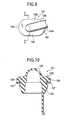
- Fig. 9 is a plan view showing an important portion of a conventional grommet;
- Fig. 10 is a cross-sectional view taken along the line X-X of Fig. 9;
- Fig. 11 is a plan view of the grommet of Fig. 9 mounted on a panel; and
- Fig. 12 is a cross-sectional view taken along the line XII-XII of Fig. 11.
-
- A first embodiment of a grommet of the present invention will now be described with reference to Figs. 1 to 4. The grommet 1 (shown in Figs. 1 to 4), forming the first embodiment of the invention, is mounted in a hole 3 (indicated in a broken line in Fig. 3) formed through a panel 2 (shown in Fig. 3) forming a vehicle body of a vehicle such as an automobile. The
grommet 1 is formed into a tubular shape, and a wire harness, which is to be installed on the automobile, is passed through the inside of thegrommet 1. Thegrommet 1 prevents moisture, such as water, from depositing on the wire harness. In the example shown in Fig. 3, thehole 3 is an elongate hole of a generally oval or elliptical shape. - The
grommet 1 is made of elastically-deformable rubber or the like. As shown in Fig. 1, thegrommet 1 of an integral construction includes agrommet body 4 of a tubular shape, a fitting portion 5 (shown in Fig. 2), aflange portion 6, a lip 7 (shown in Fig. 2), and projectedportions 10. The wire harness is passed through the inside of thegrommet body 4. Thefitting portion 5 is formed at an end of thegrommet body 4, and is fitted in thehole 3 as shown in Fig. 4. Thefitting portion 5 of a tubular shape is varying in wall thickness gradually in a direction away from thegrommet body 4. The interior of thefitting portion 5 is in communication with a space K (described later). - The
flange portion 6 is formed at the end of thegrommet body 4 at which thefitting portion 5 is formed. Theflange portion 6 extends generally radially outwardly from thegrommet body 4 at the end thereof. Theflange portion 6 of an integral construction includes a pair ofstraight portions 8, and a pair of arcuate portions 9. - The pair of
straight portions 8 are spaced from each other. The pair ofstraight portions 8 are disposed parallel to each other. The pair of arcuate portions 9 are spaced from each other. The arcuate portions 9 are connected at their opposite ends to the pair ofstraight portions 8. Thus, each of the arcuate portions 9 interconnects the pair ofstraight portions 8. - The pair of
straight portions 8 and the pair of arcuate portions 9 are connected together in the above-mentioned manner, and thestraight portions 8 and the arcuate portions 9 project generally radially outwardly from thegrommet body 4. Therefore, the wire harness is passed through the space K (shown in Figs.. 2 and 4) defined by the pair ofstraight portions 8 and the pair of arcuate portions 9. The space K is in communication with the interior of thegrommet body 4. - The
lip 7 is formed at outer edge portions of the twostraight portions 8 and two arcuate portions 9 over the entire periphery. Namely, thelip 7 is formed at the outer peripheral edge portion of theflange portion 6 over the entire periphery thereof. When thefitting portion 5 is fitted in thehole 3, thelip 7 is held in contact with thepanel 2, and is elastically deformed by thepanel 2, with its distal end directed outwardly of theflange portion 6. Thelip 7 cooperates with thepanel 2 to form a liquid-tight seal therebetween, thereby preventing a liquid, such as water, from intruding into thefitting portion 5 and the grommet body 4 (that is, into the grommet 1). - The projected
portions 10 project outwardly respectively from the pair ofstraight portions 8 of the flange portion 6 (that is, generally radially outwardly of the grommet 1). As shown in Fig. 1, the projectedportions 10 are formed respectively at central portions of the pair ofstraight portions 8, and extend along the direction of opposing of the pair of arcuate portions 9 to each other (that is, the direction of spacing of the arcuate portions from each other). Each projectedportion 10 is formed such that the amount of projecting of the projectedportion 10 from the associatedstraight portion 8 is decreasing gradually toward each arcuate portion 9. - The projected
portions 10 project from thestraight portions 8 of theflange portion 6, respectively, and thelip 7 is formed at the outer peripheral edge portion of theflange portion 6. Therefore, the projectedportions 10 are disposed immediately adjacent to the proximal end of thelip 7. Since each projectedportion 10 projects from the associatedstraight portion 8 of theflange portion 6, the combined thickness of thestraight portion 8 and projectedportion 10 of theflange portion 6 is larger than the thickness of the arcuate portion 9. Since the amount of projecting of the projectedportion 10 from the associatedstraight portion 8 is decreasing gradually toward each arcuate portion 9, the combined thickness of thestraight portion 8 and projectedportion 10 of theflange portion 6 is the largest at the central portion of thestraight portion 8. - In this embodiment, the projected
portions 10 project outwardly from the pair of thestraight portions 8, respectively. The amount of projecting of the projectedportion 10 from the associatedstraight portion 8 is decreasing gradually toward each arcuate portion 9. The projectedportion 10 is provided at the central portion of thestraight portion 8. The combined thickness of the projectedportion 10 andstraight portion 8 is the largest at the central portion of thestraight portion 8. - Therefore, strain, developing when the
fitting portion 5 is fitted in thehole 3, and is mounted on thepanel 2, is supported by the projectedportions 10. Since the combined thickness of the projectedportion 10 andstraight portion 8 is the increased thickness, thestraight portion 8 is less liable to be elastically deformed. Therefore, even if eachstraight portion 8 and its associated projectedportion 10 are elastically deformed when the grommet is mounted on thepanel 2, thestraight portion 8 and the associated projectedportion 10 become straight along the direction of spacing of the pair of arcuate portions 9 from each other, as shown in Fig. 3. Therefore, eachstraight portion 8 and the associated projectedportion 10 will not be elastically deformed or recessed toward the inside of thegrommet 1. Therefore, thegrommet 1, when mounted on thepanel 2, is prevented from detracting from the appearance. - Strain, developing when the grommet is mounted on the
panel 2, is supported by the projectedportions 10 and thestraight portions 8. Therefore, when the grommet is mounted on thepanel 2, thelip 7 is prevented from being deformed under the influence of the above strain. Therefore, thelip 7 can cooperate'with thepanel 2 to form a positive liquid-tight seal therebetween. - The projected
portions 10 project outwardly from the pair ofstraight portions 8, respectively, and are disposed immediately adjacent to the proximal end of thelip 7. Therefore, the projectedportions 10 will not adversely affect the deformability of thelip 7 at all. Therefore, the mounting of thegrommet 1 on thepanel 2 will not become difficult. - Next, a second embodiment of a grommet of the invention will be described with reference to Figs. 5 to 8. Those constituent portions, identical to those of the first embodiment, will be designated by identical reference numerals, respectively, and explanation thereof will be omitted. In this embodiment, a
hole 3, formed through apanel 2, has a generally rectangular shape. Four corners of thehole 3 have a generally arcuate shape. - A
flange portion 6 of thegrommet 1 of this embodiment has an integral construction, and includes a pair of firststraight portions 11, and a pair of secondstraight portions 12, as shown in Fig. 5. Thegrommet 1 includes first projectedportions 21 and second projectedportions 22. - The pair of first
straight portions 11 are spaced from each other. The pair of firststraight portions 11 are disposed parallel to each other. The pair of secondstraight portions 12 are spaced from each other. The pair of secondstraight portions 12 are disposed parallel to each other. The secondstraight portions 12 are connected at their opposite ends to the pair of firststraight portions 11. Thus, each of the secondstraight portions 12 interconnects the pair of firststraight portions 11. - The pair of first
straight portions 11 and the pair of secondstraight portions 12 are connected together, and thestraight portions grommet body 4. Therefore, a wire harness is passed through a space K (shown in Figs. 6 and 8) defined by thestraight portions grommet body 4. The firststraight portions 11 perpendicularly intersect the secondstraight portions 12. Four corner portions of theflange portion 6, at which the firststraight portions 11 and the secondstraight portions 12 are connected together, have a generally arcuate shape. - The first projected
portions 21 project outwardly respectively from the pair of firststraight portions 11 of the flange portion 6 (that is, generally radially outwardly of the grommet 1). As shown in Fig. 5, the first projectedportions 21 are formed respectively at central portions of the pair of firststraight portions 11, and extend along the direction of opposing of the pair of secondstraight portions 12 to each other (that is, the direction of spacing of the second straight portions from each other). Each first projectedportion 21 is formed such that the amount of projecting of the first projectedportion 21 from the associated firststraight portion 11 is decreasing gradually toward each secondstraight portion 12. - The second projected
portions 22 project outwardly respectively from the pair of secondstraight portions 12 of the flange portion 6 (that is, generally radially outwardly of the grommet 1). As shown in Fig. 5, the second projectedportions 22 are formed respectively at central portions of the pair of secondstraight portions 12, and extend along the direction of opposing of the pair of firststraight portions 11 to each other (that is, the direction of spacing of the first straight portions from each other). Each second projectedportion 22 is formed such that the amount of projecting of the second projectedportion 22 from the associated secondstraight portion 12 is decreasing gradually toward each firststraight portion 11. - A
lip 7 is formed at outer edge portions of the two firststraight portions 11 and two secondstraight portions 12 over the entire periphery. Namely, thelip 7 is formed at the outer peripheral edge portion of theflange portion 6 over the entire periphery thereof. The projectedportions straight portions lip 7 is formed at the outer peripheral edge portion of theflange portion 6. Therefore, the projectedportions lip 7. Since each projectedportion straight portion portion straight portion portion straight portion straight portion - In this embodiment, the first projected
portions 21 project outwardly from the pair of the firststraight portions 11, respectively. The amount of projecting of the first projectedportion 21 from the associated firststraight portion 11 is decreasing gradually toward each secondstraight portion 12. The first projectedportion 21 is provided at the central portion of the firststraight portion 11. The combined thickness of the first projectedportion 21 and firststraight portion 11 is the largest at the central portion of the firststraight portion 11. - The second projected
portions 22 project outwardly from the pair of the secondstraight portions 12, respectively. The amount of projecting of the second projectedportion 22 from the associated secondstraight portion 12 is decreasing gradually toward each firststraight portion 11. The second projectedportion 22 is provided at the central portion of the secondstraight portion 12. The combined thickness of the second projectedportion 22 and secondstraight portion 12 is the largest at the central portion of the secondstraight portion 12. - Therefore, strain, developing when a
fitting portion 5 is fitted in thehole 3, and is mounted on thepanel 2, is supported by the projectedportions portion straight portion straight portion straight portion 11 and its associated projectedportion 21 are elastically deformed when the grommet is mounted on thepanel 2, the firststraight portion 11 and the associated projectedportion 21 become straight along the direction of spacing of the pair of secondstraight portions 12 from each other, as shown in Fig. 7. - Also, even if each second
straight portion 12 and its associated projectedportion 22 are elastically deformed when the grommet is mounted on thepanel 2, the secondstraight portion 12 and the associated projectedportion 22 become straight along the direction of spacing of the pair of firststraight portions 11 from each other, as shown in Fig. 7. Therefore, eachstraight portion portion grommet 1. Therefore, thegrommet 1, when mounted on thepanel 2, is prevented from detracting from the appearance. - Strain, developing when the grommet is mounted on the
panel 2, is supported by the projectedportions straight portions panel 2, thelip 7 is prevented from being deformed under the influence of the above strain. Therefore, thelip 7 can cooperate with thepanel 2 to form a positive liquid-tight seal therebetween. - Each projected
portion straight portion lip 7. Therefore, the projectedportions lip 7 at all. Therefore, the mounting of thegrommet 1 on thepanel 2 will not become difficult. - In the above second embodiment, the
grommet 1 includes the first projectedportions 21, projecting respectively from the firststraight portions 11, and the second projectedportions 22 projecting respectively from the secondstraight portions 12. In the present invention, however, there may be provided at least one of the pair of first projectedportions 21 and the pair of second projectedportions 22. Namely, only the first projectedportions 21, or only the second projectedportions 22, or both the first and second projectedportions - In these cases, the
straight portions lip 7 is suppressed, thereby preventing its waterproof effect from being lowered. In addition, the mounting of the grommet on thepanel 2 will not become difficult. - As described above, in the invention, the projected portions project outwardly from the straight portions, respectively. Therefore, strain, developing when the grommet is mounted on the panel, is supported by the projected portions. The combined thickness of each projected portion and associated straight portion is the increased thickness, and therefore the straight portion is less liable to be elastically deformed. Therefore, even if each straight portion and its associated projected portion are elastically deformed when the grommet is mounted on the panel, the straight portion and the associated projected portion become straight along the direction of spacing of the pair of arcuate portions from each other. Therefore, the straight portion and the associated projected portion will not be elastically deformed or recessed toward the inside of the grommet. Therefore, the grommet, when mounted on the panel, is prevented from detracting from the appearance.
- Strain, developing when the grommet is mounted on the panel, is supported by the projected portions. Therefore, when the grommet is mounted on the panel, the lip is prevented from being deformed under the influence of the above strain. Therefore, the lip can cooperate with the panel to form a positive liquid-tight seal therebetween.
- The projected portions project outwardly from the straight portions, respectively, and therefore the projected portions will not adversely affect the deformability of the lip at all.
- In the invention, the amount of projecting of each projected portion from the associated straight portion is decreasing gradually toward each arcuate portion. The projected portion is provided at the central portion of the straight portion. Therefore, the combined thickness of the projected portion and straight portion is the largest at the central portion of the straight portion. Therefore, when the grommet is mounted on the panel, the straight portions are less liable to be elastically deformed. Therefore, even if each straight portion and its associated projected portion are elastically deformed, the straight portion and the associated projected portion become straight along the direction of spacing of the pair of arcuate portions from each other. Therefore, the straight portion and the associated projected portion will not be elastically deformed or recessed toward the inside of the grommet. Therefore, the grommet, when mounted on the panel, is more positively prevented from detracting from the appearance.
- In the invention, the first projected portions project outwardly from the first straight portions, respectively. Therefore, strain, developing when the grommet is mounted on the panel, is supported by the first projected portions. The combined thickness of each first projected portion and associated first straight portion is the increased thickness, and therefore the first straight portion is less liable to be elastically deformed when the grommet is mounted on the panel. Even if each first straight portion and its associated first projected portion are elastically deformed, the first straight portion and the associated first projected portion become straight along the direction of spacing of the pair of second straight portions from each other. Therefore, the first straight portion and the associated first projected portion will not be elastically deformed or recessed toward the inside of the grommet. Therefore, the grommet, when mounted on the panel, is prevented from detracting from the appearance.
- Strain, developing when the grommet is mounted on the panel, is supported by the first projected portions. Therefore, when the grommet is mounted on the panel, the lip is prevented from being deformed under the influence of the above strain. Therefore, the lip can cooperate with the panel to form a positive liquid-tight seal therebetween.
- The first projected portions project outwardly from the first straight portions, respectively, and therefore the first projected portions will not adversely affect the deformability of the lip at all.
- In the invention, the amount of projecting of each first projected portion from the associated first straight portion is decreasing gradually toward each second straight portion. The first projected portion is provided at the central portion of the first straight portion. Therefore, the combined thickness of the first projected portion and first straight portion is the largest at the central portion of the first straight portion. Therefore, when the grommet is mounted on the panel, the first straight portions are less liable to be elastically deformed. Therefore, even if each first straight portion and its associated first projected portion are elastically deformed, the first straight portion and the associated first projected portion become straight along the direction of spacing of the pair of second straight portions from each other. Therefore, the first straight portion and the associated first projected portion will not be elastically deformed or recessed toward the inside of the grommet. Therefore, the grommet, when mounted on the panel, is more positively prevented from detracting from the appearance.
- In the invention, the second projected portions project outwardly from the second straight portions, respectively. Therefore, strain, developing when the grommet is mounted on the panel, is supported by the second projected portions. The combined thickness of each second projected portion and associated second straight portion is the increased thickness, and therefore when the grommet is mounted on the panel, the second straight portions are less liable to be elastically deformed. Therefore, even if each second straight portion and its associated second projected portion are elastically deformed, the second straight portion and the associated second projected portion become straight along the direction of spacing of the pair of first straight portions from each other. Therefore, the second straight portion and the associated second projected portion will not be elastically deformed or recessed toward the inside of the grommet. Therefore, the grommet, when mounted on the panel, is prevented from detracting from the appearance.
- Strain, developing when the grommet is mounted on the panel, is supported by the second projected portions. Therefore, when the grommet is mounted on the panel, the lip is prevented from being deformed under the influence of the above strain. Therefore, the lip can cooperate with the panel to form a positive liquid-tight seal therebetween.
- The second projected portions project outwardly from the second straight portions, respectively, and therefore the second projected portions will not adversely affect the deformability of the lip at all.
- In the invention, the amount of projecting of each second projected portion from the associated second straight portion is decreasing gradually toward each first straight portion. The second projected portion is provided at the central portion of the second straight portion. Therefore, the combined thickness of the second projected portion and second straight portion is the largest at the central portion of the second straight portion. Therefore, when the grommet is mounted on the panel, the second straight portions are less liable to be elastically deformed. Therefore, even if each second straight portion and its associated second projected portion are elastically deformed, the second straight portion and the associated second projected portion become straight along the direction of spacing of the pair of first straight portions from each other. Therefore, the second straight portion and the associated second projected portion will not be elastically deformed or recessed toward the inside of the grommet. Therefore, the grommet, when mounted on the panel, is more positively prevented from detracting from the appearance.
- In the invention, the first projected portions project outwardly from the first straight portions, respectively, and the second projected portions project outwardly from the second straight portions, respectively. Therefore, strain, developing when the grommet is mounted on the panel, is supported by the first and second projected portions. The combined thickness of each first projected portion and associated first straight portion, as well as the combined thickness of each second projected portion and associated second straight portion, is the increased thickness, and therefore the first and second straight portions are less liable to be elastically deformed when the grommet is mounted on the panel. Therefore, each first straight portion and its associated first projected portion, as well as each second straight portion and its associated second projected portion, even if elastically deformed, become straight, and will not be elastically deformed or recessed toward the inside of the grommet. Therefore, the grommet, when mounted on the panel, is prevented from detracting from the appearance.
- Strain, developing when the grommet is mounted on the panel, is supported by the first and second projected portions. Therefore, when the grommet is mounted on the panel, the lip is prevented from being deformed under the influence of the above strain. Therefore, the lip can cooperate with the panel to form a positive liquid-tight seal therebetween.
- The first projected portions project outwardly from the first straight portions, respectively, and the second projected portions project outwardly from the second straight portions, respectively, and therefore the first and second projected portions will not adversely affect the deformability of the lip at all. Therefore, the lip can cooperate with the panel to form a positive liquid-tight seal therebetween.
- In the invention, the combined thickness of the first projected portion and first straight portion is the largest at the central portion of the first straight portion. The combined thickness of the second projected portion and second straight portion is the largest at the central portion of the second straight portion. Therefore, when the grommet is mounted on the panel, the first and second straight portions are less liable to be elastically deformed. Therefore, each first straight portion and its associated first projected portion, as well as each second straight portion and its associated second projected portion, even if elastically deformed, become straight, and will not be elastically deformed or recessed toward the inside of the grommet. Therefore, the grommet, when mounted on the panel, is more positively prevented from detracting from the appearance.
Claims (8)
- A grommet comprising:wherein said pair of straight portions and said pair of arcuate portions define a space through which a wire harness is adapted to be passed;a pair of straight portions spaced from each other;a pair of arcuate portions which are spaced from each other and interconnect said pair of straight portions;
a fitting portion of a tubular shape for fitting in a hole which is formed on a panel, an interior of said fitting portion being in communication with said space;
a lip which is formed at an outer edge portion of said pair of straight portions and said pair of arcuate portions over an entire periphery thereof, and which is adapted to be held in contact with said panel upon fitting of said fitting portion in said hole, thereby forming a liquid-tight seal between said lip and said panel; and
a projected portion projecting outwardly from one of said pair of straight portions. - A grommet according to claim 1, wherein said projected portion is formed at a central portion of one of said pair of straight portions, and extends along a direction of spacing of said pair of arcuate portions from each other, and an amount of projecting of said projected portion from the associated straight portion is decreasing gradually toward each arcuate portion.
- A grommet comprising:wherein said pair of first straight portions and said pair of second straight portions define a space through which a wire harness is adapted to be passed;a pair of first straight portions spaced from each other;a pair of second straight portions which are spaced from each other, and interconnect said pair of first straight portions;
a fitting portion of a tubular shape for fitting in a hole, which is formed on a panel, and an interior of said fitting portion being in communication with said space;
a lip which is formed at an outer edge portion of said pair of first straight portions and said pair of second straight portions over an entire periphery thereof, and which is adapted to be held in contact with said panel upon fitting of said fitting portion in said hole, thereby forming a liquid-tight seal between said lip and said panel; and
a first projected portion projecting outwardly from said pair of first straight portions. - A gronunet according to claim 3, wherein said first projected portion is formed at a central portion of one of said pair of first straight portions, and extends along a direction of spacing of said pair of second straight portions from each other, and an amount of projecting of said first projected portion from the associated first straight portion is decreasing gradually toward each second straight portion.
- A grommet comprising:wherein said pair of first straight portions and said pair of second straight portions define a space through which a wire harness is adapted to be passed;a pair of first straight portions spaced from each other;a pair of second straight portions which are spaced from each other, and interconnect said pair of first straight portions;
a fitting portion of a tubular shape for fitting in a hole which is formed in a panel, an interior of said fitting portion being in communication with said space;
a lip which is formed at an outer edge portion of said pair of first straight portions and said pair of second straight portions over an entire periphery thereof, and which is adapted to be held in contact with said panel upon fitting of said fitting portion in said hole, thereby forming a liquid-tight seal between said lip and said panel; and
a second projected portion projecting outwardly from said pair of second straight portions. - A grommet according to claim 5, wherein said second projected portion is formed at a central portion of one of said pair of second straight portions, and extends along a direction of spacing of said pair of first straight portions from each other, and an amount of projecting of said second projected portion from the associated second straight portion is decreasing gradually toward each first straight portion.
- A grommet comprising:wherein said pair of first straight portions and said pair of second straight portions define a space through which a wire harness is adapted to be passed;a pair of first straight portions spaced from each other;a pair of second straight portions which are spaced from each other, and interconnect said pair of first straight portions;
a fitting portion of a tubular shape for fitting in a hole which is formed in a panel, an interior of said fitting portion being in communication with said space;
a lip which is formed at an outer edge portion of said pair of first straight portions and said pair of second straight portions over an entire periphery thereof, and which is adapted to be held in contact with said panel upon fitting of said fitting portion in said hole, thereby forming a liquid-tight seal between said lip and said panel;
a first projected portion projecting outwardly from one of said pair of first straight portions; and
a second projected portion projecting outwardly from one of said pair of second straight portions. - A grommet according to claim 7, wherein said first projected portion is formed at a central portion of one of said first straight portion, and extends along a direction of spacing of said pair of second straight portions from each other, and an amount of projecting of said first projected portion from the associated first straight portion is decreasing gradually toward each second straight portion; and
said second projected portion is formed at a central portion of one of said second straight portion, and extends along a direction of spacing of said pair of first straight portions from each other, and an amount of projecting of said second projected portion from the associated second straight portion is decreasing gradually toward each first straight portion.
Applications Claiming Priority (2)
| Application Number | Priority Date | Filing Date | Title |
|---|---|---|---|
| JP2001131914A JP3943858B2 (en) | 2001-04-27 | 2001-04-27 | Grommet |
| JP2001131914 | 2001-04-27 |
Publications (3)
| Publication Number | Publication Date |
|---|---|
| EP1253049A2 true EP1253049A2 (en) | 2002-10-30 |
| EP1253049A3 EP1253049A3 (en) | 2003-04-23 |
| EP1253049B1 EP1253049B1 (en) | 2006-05-24 |
Family
ID=18980016
Family Applications (1)
| Application Number | Title | Priority Date | Filing Date |
|---|---|---|---|
| EP02100416A Expired - Lifetime EP1253049B1 (en) | 2001-04-27 | 2002-04-25 | Grommet |
Country Status (4)
| Country | Link |
|---|---|
| US (1) | US6760957B2 (en) |
| EP (1) | EP1253049B1 (en) |
| JP (1) | JP3943858B2 (en) |
| DE (1) | DE60211590T2 (en) |
Families Citing this family (5)
| Publication number | Priority date | Publication date | Assignee | Title |
|---|---|---|---|---|
| DE102004051590B3 (en) * | 2004-10-22 | 2005-09-29 | A. Raymond & Cie | Device for covering a recess in a carrier part |
| JP5758645B2 (en) * | 2011-02-14 | 2015-08-05 | 矢崎総業株式会社 | Grommet |
| JP5736963B2 (en) * | 2011-05-26 | 2015-06-17 | 住友電装株式会社 | Grommet |
| US20150040345A1 (en) * | 2013-08-06 | 2015-02-12 | Honda Motor Co., Ltd. | Vehicle grommet and method |
| DE102023101656A1 (en) * | 2023-01-24 | 2024-07-25 | Bayerische Motoren Werke Aktiengesellschaft | Component and motor vehicle |
Family Cites Families (8)
| Publication number | Priority date | Publication date | Assignee | Title |
|---|---|---|---|---|
| JPH01124612A (en) | 1987-11-06 | 1989-05-17 | Asahi Chem Ind Co Ltd | Yarn for carpet |
| JP3075445B2 (en) * | 1992-11-04 | 2000-08-14 | 矢崎総業株式会社 | Mounting method and mounting structure of connector to panel |
| JP2947000B2 (en) * | 1993-06-08 | 1999-09-13 | 住友電装株式会社 | Wire harness waterproofing method and waterproofing structure |
| US5739475A (en) * | 1994-04-21 | 1998-04-14 | Inoac Corporation | Grommet for protecting a wire harness with structure for ensuring flush seating |
| JPH07296661A (en) * | 1994-04-27 | 1995-11-10 | Furukawa Electric Co Ltd:The | Grommet |
| JPH10302563A (en) * | 1997-04-22 | 1998-11-13 | Yazaki Corp | Grommet |
| JP3175647B2 (en) * | 1997-07-04 | 2001-06-11 | 住友電装株式会社 | Grommet |
| JP3520797B2 (en) * | 1999-03-02 | 2004-04-19 | 住友電装株式会社 | Grommet |
-
2001
- 2001-04-27 JP JP2001131914A patent/JP3943858B2/en not_active Expired - Fee Related
-
2002
- 2002-04-25 DE DE60211590T patent/DE60211590T2/en not_active Expired - Fee Related
- 2002-04-25 EP EP02100416A patent/EP1253049B1/en not_active Expired - Lifetime
- 2002-04-29 US US10/133,741 patent/US6760957B2/en not_active Expired - Fee Related
Non-Patent Citations (1)
| Title |
|---|
| None |
Also Published As
| Publication number | Publication date |
|---|---|
| JP2002325342A (en) | 2002-11-08 |
| EP1253049A3 (en) | 2003-04-23 |
| JP3943858B2 (en) | 2007-07-11 |
| US6760957B2 (en) | 2004-07-13 |
| DE60211590T2 (en) | 2007-01-18 |
| US20020162195A1 (en) | 2002-11-07 |
| DE60211590D1 (en) | 2006-06-29 |
| EP1253049B1 (en) | 2006-05-24 |
Similar Documents
| Publication | Publication Date | Title |
|---|---|---|
| US6088874A (en) | Grommet | |
| US20030061680A1 (en) | Resin inner member-provided grommet | |
| US8628093B2 (en) | Grommet | |
| JP2001267005A (en) | Waterproof dummy connector | |
| JPH04193622A (en) | Structure for installing glass run | |
| JP3765220B2 (en) | Grommet | |
| US6536161B2 (en) | Weather strip for hinged double doors | |
| EP1253049A2 (en) | Grommet | |
| JP3638811B2 (en) | Grommet and grommet waterproof structure | |
| JP2001189575A (en) | Seal structure of water-proof case | |
| JP2004242434A (en) | Waterproof structure of electrical junction box | |
| JPH10172642A (en) | Electric plug connector | |
| JP3447476B2 (en) | Wiring stopper | |
| JP2003141959A (en) | Grommet | |
| JPH11273481A (en) | Cable bushing | |
| JPH07296661A (en) | Grommet | |
| KR100339213B1 (en) | apparatus for sealing for automobile door | |
| JP3887112B2 (en) | Weatherstrip seal structure | |
| JP3584610B2 (en) | Car lamp structure | |
| KR100339218B1 (en) | apparatus for sealing for automobile door | |
| JPH0612981Y2 (en) | Automotive weather strip | |
| JP2567531Y2 (en) | Panel-mounted connector seal structure | |
| JP2000016195A (en) | Grommet | |
| JP3936531B2 (en) | Grommet mating structure | |
| JP2007223448A (en) | Connection structure between door mirror and belt seal outer |
Legal Events
| Date | Code | Title | Description |
|---|---|---|---|
| PUAI | Public reference made under article 153(3) epc to a published international application that has entered the european phase |
Free format text: ORIGINAL CODE: 0009012 |
|
| AK | Designated contracting states |
Kind code of ref document: A2 Designated state(s): AT BE CH CY DE DK ES FI FR GB GR IE IT LI LU MC NL PT SE TR |
|
| AX | Request for extension of the european patent |
Free format text: AL;LT;LV;MK;RO;SI |
|
| PUAL | Search report despatched |
Free format text: ORIGINAL CODE: 0009013 |
|
| AK | Designated contracting states |
Designated state(s): AT BE CH CY DE DK ES FI FR GB GR IE IT LI LU MC NL PT SE TR |
|
| AX | Request for extension of the european patent |
Extension state: AL LT LV MK RO SI |
|
| 17P | Request for examination filed |
Effective date: 20031008 |
|
| AKX | Designation fees paid |
Designated state(s): DE FR GB |
|
| 17Q | First examination report despatched |
Effective date: 20040817 |
|
| GRAP | Despatch of communication of intention to grant a patent |
Free format text: ORIGINAL CODE: EPIDOSNIGR1 |
|
| GRAS | Grant fee paid |
Free format text: ORIGINAL CODE: EPIDOSNIGR3 |
|
| GRAA | (expected) grant |
Free format text: ORIGINAL CODE: 0009210 |
|
| AK | Designated contracting states |
Kind code of ref document: B1 Designated state(s): DE FR GB |
|
| REG | Reference to a national code |
Ref country code: GB Ref legal event code: FG4D |
|
| REF | Corresponds to: |
Ref document number: 60211590 Country of ref document: DE Date of ref document: 20060629 Kind code of ref document: P |
|
| ET | Fr: translation filed | ||
| PLBE | No opposition filed within time limit |
Free format text: ORIGINAL CODE: 0009261 |
|
| STAA | Information on the status of an ep patent application or granted ep patent |
Free format text: STATUS: NO OPPOSITION FILED WITHIN TIME LIMIT |
|
| 26N | No opposition filed |
Effective date: 20070227 |
|
| PGFP | Annual fee paid to national office [announced via postgrant information from national office to epo] |
Ref country code: DE Payment date: 20090428 Year of fee payment: 8 Ref country code: FR Payment date: 20090417 Year of fee payment: 8 |
|
| PGFP | Annual fee paid to national office [announced via postgrant information from national office to epo] |
Ref country code: GB Payment date: 20090422 Year of fee payment: 8 |
|
| GBPC | Gb: european patent ceased through non-payment of renewal fee |
Effective date: 20100425 |
|
| REG | Reference to a national code |
Ref country code: FR Ref legal event code: ST Effective date: 20101230 |
|
| PG25 | Lapsed in a contracting state [announced via postgrant information from national office to epo] |
Ref country code: DE Free format text: LAPSE BECAUSE OF NON-PAYMENT OF DUE FEES Effective date: 20101103 |
|
| PG25 | Lapsed in a contracting state [announced via postgrant information from national office to epo] |
Ref country code: GB Free format text: LAPSE BECAUSE OF NON-PAYMENT OF DUE FEES Effective date: 20100425 |
|
| PG25 | Lapsed in a contracting state [announced via postgrant information from national office to epo] |
Ref country code: FR Free format text: LAPSE BECAUSE OF NON-PAYMENT OF DUE FEES Effective date: 20100430 |