The present invention relates to a small-sized thermal printer
mounted on a desk-top type electronic apparatus that is installed
in a shop or on various portable information devices, and more
particularly to a thermal printer having a structure in which, even
if a platen roller is of a detachable type, there is no positional
displacement between a thermal head and a platen roller during the
printing operation.
A conventional example of a general small-sized thermal printer
provided with a line-type thermal head will now be described with
reference to Figs. 7 to 10.
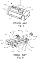
The thermal printer P2 shown in Fig. 7 is provided with a platen
roller 102 pivoted rotatably to a frame 101, a head support member
103 provided with a thermal head (not shown in Fig. 7) facing the
platen roller 102 and a platen spring 104 for giving a biasing force
for pressing this head support member 103 against the platen roller
102.
Also, the thermal printer P2 of Fig. 7 is provided with a head-up
lever 105 or the like having a cam for moving the above-described
head support member 103 apart from the platen roller 102 during
the maintenance operations for the paper clog due to paper jam or
for replacement of recording paper. The head-up mechanism composed
of this head-up lever 105 is a mechanism provided for the purpose
of making it possible to manually separate the platen roller 102
and the head support member (thermal head) 103 away from each other
by a predetermined distance (for example, at an interval of several
millimeters) in order to enable, for example, replacement operation
of a thermal sensitive type recording paper or operations for removing
paper clog due to paper jam that occurs almost unavoidably.
In the thermal printer P2 shown in Fig. 7, since the platen
roller 102 is of a fixed type such that the roller cannot be detached,
there is an advantage that the positional precision between the
thermal head and the platen roller 102 is high.
Also, a driven gear (not shown in the drawing) to be engaged
with a gear train provided with a motor M as a drive source is provided
on one side (on the right end side in Fig. 7) of the platen roller
102. Since the roller 102 is of the fixed type as described above,
the force applied to the driven gear when the platen roller 102
is rotationally driven may be absorbed by a shaft fastening portion
of the platen roller 102. Thus, there is no problem that the platen
roller 102 is lifted during the driving operation to cause positional
displacement relative to the thermal head.
Although the thermal printer P2 has the advantages as described
above, the thermal printer has a disadvantage that the
operationability in inserting the recording paper is poor. Namely,
when the recording paper is to be inserted as described above, the
head-up lever 105 is operated to separate the thermal head and the
platen roller 102 away from each other by several millimeters and
the recording paper is inserted into the gap thus produced. However,
insertion of the recording paper is often difficult when the recording
paper is curled or its end is folded. Accordingly, there is a demand
to improve its structure.
Therefore, a thermal printer P3 that has a structure such that
a platen roller 202 may be detached as shown in Figs. 8 and 9 has
been developed.
This thermal printer P3 is composed of a frame 202 having a
pair of side wall portions 201a and 201b arranged to face each other
through a predetermined interval in a paper width direction, a head
support member 204 for holding a thermal head 203, a platen roller
attaching/detaching mechanism A' for detachably and rotatably
bearing the platen roller 210 by means of the above-described pair
of side wall portions 201a and 201b, a pressing mechanism B' for
bringing the surface of the thermal head 203 into contact with the
circumferential surface of the above-described platen roller 210
with predetermined pressing force, a gear transmission mechanism
G1 for transmitting the rotational driving force of the motor M
to a driven gear G2 fixed at one end (at the right end in the drawing)
of the above-described platen roller 210, and so on. In the
structural example shown in Figs. 8 and 9, the pressing mechanism
B' is formed integrally with the platen roller attaching/detaching
mechanism A' and they operate as an integral mechanism as a whole.
As shown in Fig. 9, the platen roller attaching/detaching
mechanism (pressing mechanism B') A' is provided with a swing member
300 having a U-shape as a whole and which is slightly wider than
the thermal head 203 (head support member 204). The swing member
300 is provided with a pair of hook-like latch portions 301 to be
engaged with both shaft ends (210a and 210b) of the platen roller
so as to draw the platen roller 210 toward surface of the thermal
head 203, a pair of arm portions 302 for guiding the latch portions
301 to the rear side of the head support member 204 along both sides
of the thermal head 203 (head support member 204), and an elastic
member support portion 303 provided at its both ends with arm portions
302 for supporting springs S10, S10 as the spring members and arranged
in the width direction in the rear of the head support member 204.
The swing member 300 and the head support member 204 are swingably
borne through a support shaft 400 (see Fig. 10) provided between
the side wall portions 201a and 201b.
Furthermore, a release lever 500 serving as an engagement
release means for swinging the swing member 300 itself forwardly
so as to release the engagement between the latch portions 301 and
the both shaft ends 210a and 210b of the platen roller 210 is provided
in the rear of the swing member 300 (see Fig. 8).
The thermal printer P3 having such a structure has such an
advantage that, when giving a new supply of the recording paper
or the paper clog occurred, the release lever 500 is operated to
activate the platen roller attaching/detaching mechanism A' to
remove the platen roller 210 from the frame 202 to thereby make
it possible to perform the removal of the paper causing the paper
clog, giving a new supply of the recording paper, or the like.
Nevertheless, the thermal printer P3 shown in Figs. 8 and 9
has the above-described advantage, however, the printer suffers
from such a disadvantage that the positional displacement between
the thermal head 203 and the platen roller 210 can easily occur
due to such arrangement that the platen roller 210 is of the detachable
type.
Namely, in this thermal printer P3, various forces (F1, F2,
and F3) as shown in Fig. 10 are applied to the platen roller 210
and the composite force (F4) thereof works in a direction to lift
the platen roller 210. Accordingly, the positions of the thermal
head 203 and the platen roller 210 are displaced from each other
upon the execution of the printing operation.
More specifically, under the state where the shaft end 210
of the platen roller 210 at which the driver gear G2 is provided,
is being held to the latch portion 301, the pressing force F1 to
be applied via the thermal head 203 (head support member 204), the
pressing force F2 to be applied via the arm portion 302 and the
latch portion 301 (i.e., the force for drawing the platen roller
210 to the side of the thermal head 203) and the pressing force
F3 to be applied via the driven gear G2 due to the drive of the
gear transmission mechanism G1 upon the execution of the printing
operation, which works in counterclockwise direction in the drawing,
are applied to that shaft end 210. In particular, a part of the
rotational force of F3 is converted into the force that works in
a direction for moving the shaft end 210b apart from the latch portion
301, due to frictional force between the latch portion 301 and the
circumferential surface of the shaft end 210b. Then, the force F4
which works in a direction for lifting the driven gear G2 side of
the platen roller 210 away from the latch portion 301 is generated
as the composite force of these forces F1, F2 and F3. As a result,
there is a problem that the positional relationship between the
thermal head 203 and the platen roller 210 is deviated from the
right positional relationship.
As an approach to prevent such a lifting phenomenon of the
platen roller 210, the spring pressure of the springs S10, S10 as
the elastic members may be increased (for example, by using springs
having higher elasticity instead or increasing the compression
amount of the springs) to strengthen the pressing forces F1 and
F2 to be applied to the roller 210, to thereby practically suppress
the effect of the composite force F4. However, if the spring force
of the springs S10, S10 is excessively increased, the frictional
force between the circumferential surface of the platen roller 210
and the thermal head 203 and the frictional force between the latch
portion 301 and the circumferential surface of the shaft end 210b
are increased to increase the load on the motor M for rotating the
platen roller 210. As a result, a new problem occurs such that the
rpm of the platen roller 210 (delivery speed of the recording paper)
is reduced, resulting in decreased printing speed.
In order to overcome the above-noted problems, an object of
the present invention is to provide a thermal printer that may prevent
occurrence of the lifting phenomenon of the platen roller without
decreasing the printing speed.
In order to attain this object, according to the present
invention, there is provided a thermal printer comprising: a frame
(1) having a pair of side wall portions (2a and 2b) arranged to
face each other at a predetermined interval in a paper width direction;
a head support member (4) for holding a thermal head (3); a platen
roller attaching/detaching mechanism (A) for detachably and
rotatably bearing a platen roller (10) by the above-described pair
of side wall portions; a pressing mechanism (B, coil springs S1
and S2) for bringing a surface of the above-described thermal head
into contact with a circumferential surface of the above-described
platen roller with predetermined pressing force; and a gear
transmission mechanism (G1) for transmitting a rotational driving
force of a motor (M) to a driven gear (G2) fixed at one end of the
above-described platen roller, wherein a pressing force applied
on a shaft end on the driven gear side of the above-described platen
roller by the above-described pressing mechanism is made to be within
a range of 1.3 to 3.0 times of the pressing force applied on the
other shaft end.
Thus, it is possible to prevent the lifting phenomenon of the
platen roller upon the execution of the printing operation and to
thus prevent displacement between the platen roller and the thermal
head. In addition, pressing force applied on a shaft end on the
driven gear side of the platen roller by the above-described pressing
mechanism is made to be within a range of 1.3 to 3.0 times of pressing
force applied on the other shaft end, whereby it is possible to
suppress as much as possible the increase of the load on the motor
caused by the frictional force between the circumferential surface
of the platen roller and the thermal head and the frictional force
between the latch portion and the circumferential surface of the
shaft end to thereby avoid reduction in the printing speed.
Incidentally, it is preferable that the average of the total
pressure to be applied to the circumferential surface of the platen
roller by the above-described pressing mechanism be in the range
of 15 to 35 g/mm. Thus, it is possible to suppress the increase
of the load on the motor more effectively and thus to avoid the
reduction in printing speed more reliably.
Also, the above-described pressing mechanism is formed
integrally with the above-described platen roller
attaching/detaching mechanism, the above-described platen roller
attaching/detaching mechanism is provided with a swing member having
a U-shape as a whole and which is slightly wider than the
above-described thermal head, the swing member is provided with
a pair of latch portions to be engaged with both shaft ends of the
above-described platen roller so as to draw the platen roller toward
the surface of the above-described thermal head, a pair of arm portions
for guiding the above-described latch portions along both sides
of the above-described thermal head to the rear side of the
above-described thermal head, and an elastic member support portion
provided on its both sides with the above-described arm portions
and arranged in a width direction in the rear of the above-described
head support member for supporting elastic members, the
above-described swing member and the above-described head support
member are swingably supported through a support shaft provided
between the above-described side wall portions, an engagement
release means for moving the swing member to thereby release the
engagement between the above-described latch portions and the
above-described platen roller is provided in the above-described
swing member, and one or two or more elastic members adapted such
that pressing force applied thereby on a shaft end on the driven
gear side of the above-described platen roller is 1.3 to 3.0 times
larger than that applied on the other shaft end may be held between
the elastic member support portion of the above-described swing
member and the above-described head support member. Thus, it is
possible to prevent the lifting phenomenon of the platen roller
upon the execution of the printing operation to thereby prevent
displacement between the platen roller and the thermal head.
Also, two or more above-described elastic members may be used
and each of the above-described elastic members is arranged and
positioned such that a barycenter of pressure applied on the
above-described platen roller is deflected toward the shaft end
on the driven gear side of the above-described platen roller by
7 to 25% whereby the pressing force applied on the shaft end on
the driven gear side of the above-described platen roller may be
1.3 to 3.0 times larger than that applied on the other shaft end.
Thus, simply by suitable changing the arrangement positions of the
elastic members, it is possible to achieve prevention of the lifting
phenomenon of the platen roller upon the execution of the printing
operation.
Also, in the case where two or more above-described elastic
members are used, elastic members having the same elasticity may
be used. In that case, the compression amounts of the respective
members are varied so that the pressing force applied on the shaft
end on the driven gear side of the above-described platen roller
may be 1.3 to 3.0 times larger than that applied on the other shaft
end. Thus, it is possible to use elastic members of identical
specifications. Therefore, it is possible to achieve prevention
of the lifting phenomenon of the platen roller upon the execution
of the printing operation without increasing the manufacture cost.
Also, in the case where elastic members having different
elasticity are used as the above-described elastic members, each
elastic member is arranged at the equal distance from the center,
whereby due to the difference in the elasticity, the pressing force
applied on the shaft end on the driven gear side of the above-described
platen roller may be 1.3 to 3.0 times larger than that applied on
the other shaft end. Thus, by suitably arranging two or more elastic
members having different elasticity, it is possible to achieve
prevention of the lifting phenomenon of the platen roller upon the
execution of the printing operation.
Incidentally, the above-described elastic member may be made
of a spring in general, rubber, synthetic resin or the like.
Embodiments of the present invention will now be described
by way of further example only and with reference to the
accompanying drawings, in which:-
Preferred embodiments of the present invention will now be
described with reference to the accompanying drawings.
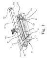
Fig. 1 is a perspective view showing one embodiment of a thermal
printer P1 according to the present invention. Fig. 2 is a schematic
plan view showing a primary part of the thermal printer P1.
The thermal printer P1 is composed of a frame 1 obtained by
injection molding of plastic such as polycarbonate or the like and
provided with a pair of side wall portions 2a and 2b arranged to
face each other through a predetermined interval in a paper width
direction, a head support member 4 for holding a thermal head 3
having a number of heating elements, a platen roller
attaching/detaching mechanism A for detachably and rotatably bearing
a platen roller 10 by the pair of side wall portions 2a and 2b,
a pressing mechanism B for bringing a surface of the above-described
thermal head 3 into contact with a circumferential surface of the
above-described platen roller 10 with predetermined pressing force,
a gear transmission mechanism G1 for transmitting a rotational
driving force of a motor M to a driven gear G2 fixed to one end
(right end in the drawing) of the above-described platen roller
10, and so on.
In accordance with this embodiment, the pressing mechanism
B is formed integrally with the platen roller attaching/detaching
mechanism A so that they operate as an integral mechanism as a whole.
As shown in Fig. 2, the platen roller attaching/detaching
mechanism (pressing mechanism B) A is provided with a swing member
30 having a U-shape as a whole and which is slightly wider than
the thermal head 3 (head support member 4). The swing member 30
is provided with a pair of hook-like latch portions 31 to be engaged
with both shaft ends (10a and 10b) of the platen roller so as to
draw the platen roller 10 toward the surface of the thermal head
3, a pair of arm portions 32 for guiding the latch portions 31 to
the rear side of the head support member 4 along both sides of the
thermal head 3 (head support member 4) and an elastic member support
portion 33 provided at its both ends with the arm portions 32 and
arranged in the width direction in the rear of the head support
member 4 for supporting coil springs S1, S2 as elastic members.
The swing member 30 and the head support member 4 are swingably
borne through a support shaft (not shown in the drawing) provided
between the side wall portions 2a and 2b.
Furthermore, a release lever 50 serving as an engagement
release means for swinging the swing member 30 itself forwardly
so as to releasing the engagement between the latch portions 31
and the both shaft ends 2a and 2b of the platen roller 10 is provided
in the rear of the swing member 30.
In this embodiment, the coil springs S1, S2 are arranged in
an equal distance position from right and left ends of the elastic
member support portion 33, respectively. The elasticity
coefficients E1 and E2 (E2>E1) of the respective coil springs S1
and S2 are set such that pressing force applied on a shaft end 10b
on the driven gear G2 side of the platen roller 10 is 1.3 to 3.0
times larger than pressing force applied on the other shaft 10a.
Also, the deformation amounts (compression amounts) of the coil
springs S1, S2 are determined such that the average of the total
pressure to be applied onto the circumferential surface of the platen
roller 10 may fall within the range of 15 to 35 g/mm. Thus, the
relationship between the pressing force F10 applied by the coil
spring S1 and the pressing force F11 applied by the coil spring
S2 is given as F11>F10.
Fig. 6 is a graph showing pressure characteristics which
respectively represent the case where the spring pressure difference
of the spring S1 S2 is set at 0 (zero), 1.85 times, and 3.0 times,
in the printer having the same structure as that of the thermal
printer P1 shown in Fig. 1.
In this graph, the pressing force characteristics (crash
position of the platen) are taken in the ordinate, whereas the position
on the platen roller 10 where the pressing force is applied is taken
in the abscissa. Incidentally, in this graph, the right side
corresponds to the driven gear G2 side of the platen roller 10.
As regards the pressing force characteristics, it should be
noted here that the case where the spring pressure difference between
S1 and S2 is set at 0 (zero) corresponds to the same condition as
that applies in the conventional thermal printer P3 shown in Figs.
8 and 9. As is apparent from this graph, the pressing force is
decreased as the application position thereof becomes closer to
the driven gear G2 side of the platen roller 10. This would be
due to the fact that force acts to move the shaft end 2b apart
from the latch
portion 31 is generated by the frictional force between the latch
portion 31 and the circumferential surface of the shaft end 2b to
cause the lifting phenomenon on the driven gear G2 side of the platen
roller 10.
In contrast, in can be understood that, in the case where the
spring pressure difference between springs S1 and S2 is set at 1.85
times or 3.0 times, the pressing force is kept substantially constant
irrespective of the position on the platen roller 10 at which the
pressing force is applied and the lifting phenomenon of the platen
gear 10 at its driven gear G2 side is suppressed.
Accordingly, in the thermal printer P1 according to the present
embodiment, it is possible to suppress the phenomenon in which the
platen gear 10 is lifted at the driven gear G2 side upon the execution
of the printing operation. With this, it is possible to suppress
the displacement of the relative positions of the platen roller
10 and the thermal head 3 to thereby prevent degradation of printing
quality. Also, since the average of the total pressure to be applied
onto the circumferential surface of the platen roller 10 is set
in the range of 15 to 35 g/mm, it is possible to prevent excessive
increase of the load on the motor M upon the execution of the printing
operation, and there is no fear that the printing speed is reduced.
A thermal printer P1a in accordance with a second embodiment
will now be described with reference to Fig. 3. Fig. 3 is a schematic
plan view showing a primary part of the thermal printer P1a.
Incidentally, the same reference numerals are used to indicate the
same components and structures as those of the thermal printer P1
in accordance with the first embodiment shown in the above Fig.
2. The detailed explanation thereof will be omitted.
The difference between the thermal printer P1a and the thermal
printer P1 in accordance with the first embodiment resides in the
manner in which the coil springs S1 and S3 as the elastic members
are provided. In the thermal printer P1a, springs having elasticity
coefficients E1 and E2 which are equal (i.e., E1=E2) are used as
the coil springs S1 and S3 and the compression amount of the coil
spring S3 is set to be greater than the compression amount of the
coil spring S1 to thereby attain the desired effect.
More specifically, as shown in Fig. 3, a convex portion 33a
is formed in a position where the coil spring S3 is to be arranged
on the driven gear G2 side of the platen roller 10 of the elastic
member support portion 33, and the coil S3 is disposed under compressed
condition between this convex portion 33a and the back surface of
the head support member 4. Incidentally, the height of the convex
portion 33a and the elastic coefficients of the coil springs S1
and S3 are selected such that the pressing force applied on the
shaft end 10b on the driven gear G2 side of the platen roller 10
is 1.3 to 3.0 times larger than the pressing force applied on the
other shaft end 10a and the average of the total pressure to be
applied onto the circumferential surface of the platen roller 10
is in the range of 15 to 35 g/mm. Thus, the relationship between
the pressing force F10 applied by the coil spring S1 and the pressing
force F12 applied by the coil spring S3 is given as F12>F10.
Also in the thermal printer P1a in accordance with this second
embodiment, it is possible to attain the same effect as that of
the above-described thermal printer P1. In addition, since the same
coil springs are used in the thermal printer P1a, there is an advantage
in that the management and provision of the parts becomes easier
in comparison with the thermal printer in accordance with the first
embodiment using two different springs. Incidentally, in this
embodiment, although the convex portion 33a is formed on the side
of the elastic member support portion 33 to thereby increase the
compression amount of the coil spring S3, the invention is not limited
thereto but it is possible to attain the same effect even in the
case where the convex portion is formed on the back surface of the
head support member 4.
A thermal printer P1b in accordance with a third embodiment
will now be described with reference to Fig. 4. Fig. 4 is a schematic
plan view showing a primary part of the thermal printer P1b.
Incidentally, the same reference numerals are used to indicate the
same components and structures as those of the thermal printers
P1, P1a shown in the above Figs. 2 and 3. Therefore, the detailed
description thereof will be omitted.
In the thermal printer P1b in accordance with this embodiment,
it is possible to attain the same effect as that of the above-described
thermal printers P1 and P1a by shifting the arrangement positions
of the coil springs S4 and S5 toward the driven gear G2 side of
the platen roller 10. More specifically, the barycenter of the
pressure applied on the platen roller 10 is deflected toward the
driven gear G2 side of the platen roller 10 by 7 to 25%. Namely,
in Fig. 4, when the supporting points of the platen roller 10 at
its right and left ends are Q1 and Q2, respectively, and the center
position thereof is taken as C, the coil springs S4 and S5 are disposed
such that the barycenter G of the springs is shifted toward the
driven gear G2 side of the platen roller 10 from the center of support
C by 7 to 25%. With this arrangement, the relationship between the
pressing force F14 applied on the shaft end 10b on the driven gear
G2 side of the platen roller 10 and the pressing force F13 applied
around the shaft end 10a on the other end 10a is given as F14>F13.
Thus, it is possible to suppress the lifting phenomenon of the platen
roller 10 at the driven gear G2 side thereof upon the execution
of the printing operation. Incidentally, the coil springs S4 and
S5 having the same elastic coefficient may be used or the springs
having different elastic coefficients may be used. However, it is
a matter of course that the arrangement positions of the coil springs
S4 and S5 should be changed in accordance with their elastic
coefficients.
A thermal printer P1c in accordance with a fourth embodiment
will now be described with reference to Fig. 5. Fig. 5 is a schematic
plan view showing a primary part of the thermal printer P1c.
Incidentally, the same reference numerals are used to indicate the
same components and structures as those of the thermal printers
P1, P1a, and P1b shown in the above Figs. 2, 3 and 4. Thus, the
detailed description thereof will be omitted.
In the thermal printer P1c in accordance with this embodiment,
a pressing mechanism B2 for pressing both shaft ends 10a and 10b
of the platen roller 10 from the front side is provided instead
of providing the elastic member support portion 33 and the like
in the rear of the thermal head 3 and the head support member 4.
This pressing mechanism B2 is composed of pressure members 40a and
40b for contacting with the both shaft ends 10a and 10b of the platen
roller 10 and transmitting the pressure and coil springs S6 and
S7 as elastic members provided on the rear side of each pressure
members 40a and 40b.
As the above-described respective coil springs S6 and S7 so
that the elastic coefficient E7 of S7 and the elastic coefficient
E6 of S6 are given as E7>E6 and the pressing force applied on the
shaft end 10b on the driven gear G2 side of the platen roller 10
is 1.3 to 3.0 times larger than the pressing force applied on the
other shaft end 10a and the average of the total pressure to be
applied onto the circumferential surface of the platen roller 10
is in the range of 15 to 35 g/mm.
As a result, the relationship between the pressing force F15
applied by the coil spring S6 and the pressing force F16 applied
by the coil spring S7 is given as F16>F15. Thus, it is possible
to suppress the lifting phenomenon of the platen gear 10 at the
driven gear G2 side thereof upon the execution of the printing
operation. Therefore, it is possible to suppress the displacement
of the relative positions of the platen roller 10 and the thermal
head 3 to prevent degradation of the printing quality. Also, since
the average of the total pressure to be applied onto the
circumferential surface of the platen roller 10 is set in the range
of 15 to 35 g/mm, it is possible to prevent the load on the motor
M from becoming excessively large upon the execution of the printing
operation, and there is no fear that the printing speed is reduced.
Incidentally, the invention is not limited to the case where the
elastic coefficients of the coil spring S6 and S7 are set to be
different from each other, since it is possible to attain the same
effect by suitably changing the compression amount even when springs
having the same elastic coefficient are used.
The invention made by the present inventors has been described
on the basis of the embodiments. The present invention is not limited
to the above-described embodiments but it is possible to variously
modify or change the invention without departing from the scope
thereof.
For example, in the foregoing embodiments, the case where the
coil springs are used as elastic members has been described. However,
the invention is not limited to this. It is possible to use springs
having other configurations such as leaf springs, torsion springs
or the like or to use members obtained by molding rubber or synthetic
resin as the elastic members.
As described above, according to the present invention, in
a thermal printer which at least comprises: a frame having a pair
of side wall portions (2a and 2b) arranged to face each other at
a predetermined interval in a paper width direction; a head support
member for holding a thermal head; a platen roller
attaching/detaching mechanism for detachably and rotatably bearing
a platen roller by the pair of side wall portions; a pressing mechanism
for bringing a surface of the thermal head into contact with a
circumferential surface of the platen roller; and a gear transmission
mechanism for transmitting a rotational driving force of a motor
to a driven gear fixed at one end of the platen roller; wherein
pressing force applied on a shaft end on the driven gear side of
the above-described platen roller by the above-described pressing
mechanism is made to be within a range of 1.3 to 3.0 times of pressing
force applied on the other shaft end. Thus, it is possible to prevent
the lifting phenomenon of the platen roller upon the execution of
the printing operation and thus the displacement between the platen
roller and the thermal head. In addition, since the pressing force
applied on a shaft end on the driven gear side of the platen roller
by the pressing mechanism is made to be within a range of 1.3 to
3.0 times of the pressing force applied on the other shaft end,
it is possible to suppress as much as possible the increase of the
load on the motor which is caused by the frictional force between
the circumferential surface of the platen roller and the thermal
head and the frictional force between the latch portion and the
circumferential surface of the shaft end to thereby make it possible
to avoid occurrence of reduction in the printing speed.
Although for convenience pressing force difference values
of 1.85 and 3 are shown, it has been found that the advantages
of the invention are obtained with values in the range 1.3 to
3 inclusive.