EP1251325A2 - Heat exchanger - Google Patents
Heat exchanger Download PDFInfo
- Publication number
- EP1251325A2 EP1251325A2 EP02008598A EP02008598A EP1251325A2 EP 1251325 A2 EP1251325 A2 EP 1251325A2 EP 02008598 A EP02008598 A EP 02008598A EP 02008598 A EP02008598 A EP 02008598A EP 1251325 A2 EP1251325 A2 EP 1251325A2
- Authority
- EP
- European Patent Office
- Prior art keywords
- flow paths
- corrugated plate
- plate
- fluid
- corrugated
- Prior art date
- Legal status (The legal status is an assumption and is not a legal conclusion. Google has not performed a legal analysis and makes no representation as to the accuracy of the status listed.)
- Withdrawn
Links
Images





Classifications
-
- F—MECHANICAL ENGINEERING; LIGHTING; HEATING; WEAPONS; BLASTING
- F28—HEAT EXCHANGE IN GENERAL
- F28D—HEAT-EXCHANGE APPARATUS, NOT PROVIDED FOR IN ANOTHER SUBCLASS, IN WHICH THE HEAT-EXCHANGE MEDIA DO NOT COME INTO DIRECT CONTACT
- F28D9/00—Heat-exchange apparatus having stationary plate-like or laminated conduit assemblies for both heat-exchange media, the media being in contact with different sides of a conduit wall
- F28D9/0025—Heat-exchange apparatus having stationary plate-like or laminated conduit assemblies for both heat-exchange media, the media being in contact with different sides of a conduit wall the conduits being formed by zig-zag bend plates
Definitions
- the present invention relates to a heat exchanger easy to manufacture and resistant to fluid leakage with low fluid pressure losses.
- Fig. 11A to Fig. 11C illustrate principal members of a heat exchanger divided into pieces respectively.
- Fig. 11A shows a base plate 52 to be joined on one of the surfaces of a corrugated plate 51.
- Fig. 11B shows a corrugated plate 51.
- Fig. 11C shows a cover plate 54 to be joined on the other surface of the corrugated plate.
- FIG. 10 a heat exchanger manufactured by joining members shown in Fig. 11A to Fig. 11C is illustrated.
- a plurality of flow paths 53 are formed by joining a base plate 52 on one of the surfaces of the corrugated plate 51.
- a plurality of flow paths 56 are formed by joining a body portion 55 of the cover plate 54 on the other surface of the corrugated plate 51.
- the base plate 52 and the sleeve portion 57 of the cover plate 54 are joined, and outlet ports 58, 59 for fluid A and fluid B are formed on the upper portion of the base plate 52 and on the lower portion of the body portion 55 of the cover plate respectively.
- the openings at the lower end of the heat exchanger surrounded by the base plate 52 and the cover plate 54 are inlet ports 61 for fluid A, and the inlet ports 61 are provided with hollow bodies (not shown) extending in the same direction as the length of the respective flow paths 53, 56 for supplying fluid A.
- the openings at the upper end are inlet ports 62 for fluid B, and the inlet ports 62 are provided with hollow bodies (not shown) extending in the same direction as the length of the respective flow paths 53, 56 for supplying fluid B.
- the upper end portions of the flow paths 53 and the lower end portions of the flow paths 56 are plugged up with sealing material 60 and hermetically sealed.
- heat exchange between fluid A and fluid B is performed through the corrugated plate by supplying fluid A and fluid B into the respective flow paths 53, 56 through the respective cylindrical bodies and the respective inlet ports 61, 62, and discharging out through the outlet ports 58, 59 of the respective flow paths 53, 56.
- the end portions of the corrugated plate in the vicinity of the inlet ports for fluid are plugged up with sealing material or the like and hermetically sealed.
- sealing material or the like since the corrugated plate is thin-walled and the area to be hermetically sealed is large, the sealing operation needs much time and efforts, and defective hermeticity is apt to occur, whereby fluid may be leaked from the flow paths A to the flow paths B, or from the flow paths B to the flow paths A.
- the fluid pressure losses ⁇ p in the entire heat exchanger are a value obtained by subtracting pressure increase ⁇ p out due to increase in the area at the fluid outlet from the sum of pressure losses ⁇ p in due to decrease in the area at the inlet ports of the heat exchanger and a change in flowing direction and pressure losses ⁇ P core at the time when fluid flows through the flow paths. Since ⁇ P core and ⁇ P out among the above are determined by the specification of design, decrease in pressure losses ⁇ P depends on how much ⁇ P in can be decreased.
- the first embodiment of the invention is a heat exchanger comprising: a corrugated plate; a base plate; a cover plate; a plurality of flow paths A and a plurality of flow paths B defined by said corrugated plate, said base plate and said cover plate disposed so as to interpose said corrugated plate therebetween; and said plurality of flow paths A and said plurality of flow paths B being alternately and adjacently arranged on both sides of the corrugated plate for exchanging heat between fluid A and fluid B via the corrugated plate by supplying fluid A through a plurality of flow paths A and fluid B through a plurality of flow paths B, wherein at least one of end portions of the plurality of flow paths is hermetically sealed by making partial cuts at the end portions of the corrugated plate and/or folding a part of the end portions of the corrugated plate, bending opposing ends of the corrugated plate so as to form respectively into a shape of a gable roof, bringing at least a part of the ends
- One of the objects of the invention is to provide a heat exchanger that is easy to manufacture and resistant to fluid leakage with low fluid pressure losses.
- a heat exchanger of the invention comprises: a corrugated plate; a base plate joined on one of surfaces of said corrugated plate; a cover plate joined on other surface of said corrugated plate; two types of fluid flow paths A and B defined by said corrugated plate, said base plate, and said cover plate along a longitudinal direction of said corrugated plate, said two types of fluid flow paths comprising a plurality of flow paths A defined by said one of surfaces of said corrugated plate and said base plate, and said plurality of flow paths B defined by other surface of said corrugated plate and said cover plate, said plurality of flow paths A and said plurality of flow paths B being formed separately from each other; one of upper end portions and lower end portions of said corrugated plate for forming the flow paths A, which are hermetically sealed by providing two corresponding slant surfaces, and other one of the upper end portions and lower end portions of said corrugated plate for forming the flow paths B, which are hermetically sealed by providing two corresponding slant surfaces; inlet ports for said fluid B being provided on
- said cover plate and/or said base plate are hermetically sealed with the end portions of said corrugated plate by making cuts at the end portions of the corrugated plate to leave margins so as to be capable of brazing either on said cover plate or on said base plate, and brazing said margins.
- said corrugated plate is brazed to said base plate and/or said cover plate by the brazing material in a clad corrugated plate, and said flow paths A is completely divided off said flow paths B.
- said corrugated plate comprises a cladding plate including a core material and a brazing material formed on one side or both sides of said core material.
- a cladding plate with brazing material formed on both surfaces of the core material is used as a material of the corrugated plate.
- a plurality of flow paths 3(A) are formed by joining a base plate 2 on one of the surfaces of the corrugated plate 1.
- a plurality of flow paths 6(B) are formed by joining a body portion 5 of the cover plate 4 on the other surface of the corrugated plate 1.
- the base plate 2 and the sleeve portion 7 of the cover plate 4 are joined, and outlet ports 8 for fluid A are formed on the upper portion of the base plate 2, and outlet ports 9 for fluid B are formed at the lower portion of the body portion 5 of the cover plate.
- the openings at the lower end portion surrounded by the base plate 2 and the cover plate 4 are inlet ports 28 for fluid A, and the inlet ports 28 are provided with hollow bodies (not shown) extending in the same direction as the length of the respective flow paths 3, 6 for supplying fluid A.
- the openings at the upper end are inlet ports 29 for fluid B, and the inlet ports 29 are provided with hollow bodies (not shown) extending in the same direction as the length of the respective flow paths 3, 6 for supplying fluid B.
- the end portions 10 of the corrugated plate are bent so as to be brought into contact with each other at the extremities thereof and processed into the shape of gable roofs.
- the minute gaps at the extremities 11 of the gable roofs are brazed and hermetically sealed by filling brazing material.
- the lower end portions of the flow paths 6(B), although they are not shown in Fig. 1, are brazed and hermetically sealed by the same method as that for the upper end portions of the flow paths 3.
- the corrugated plate 1 and the base plate 2, and the corrugated plate 1 and the cover plate 4 are joined by the use of adhesive agent or sealing material, so that no leakage of fluid may occur between the flow paths 3(A) and the flow paths 6(B).
- the reason why cladding material is used for the corrugated plate 1 is to hermetically seal the flow paths 3(A) and flow paths 6(B) by brazing.
- the extremities 11 are bent toward each other and brought closer, and filled with brazing material in the minute gap therebetween so as to be brazed and hermetically sealed.
- the reason is to facilitate realization of the hermeticity at the end portions 10 of the corrugated plate, and to alleviate the extent of turbulent flow in the vicinity of the fluid inlet ports 28, 29.
- corrugated plate and the base plate, and the corrugated plate and the cover plate are joined by the use of adhesive agent or sealing material, so that no leakage of fluid occurs between the flow paths 3(A) and the flow paths 6(B).
- adhesive agent or sealing material in this embodiment, the end portions of the corrugated plate area brazed, and the corrugated plate and the base plate, and the corrugated plate and the cover plate are joined by the use of adhesive agent or sealing material.
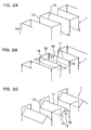
- a prescribed length of cut 13 is made along each crease 12 on the end portion 10 of the corrugated plate to form a strip 14, a strip 15, and a strip 16.
- the strip 14 and the strip 16, which are opposed each other, are bent from the ends of the cuts 13 so that the extremities 11 of the respective strips are brought closer with each other and formed into the shape of a gable roof by the use of a prescribed metal die (not shown).
- the extremities 11 of the strip 14 and the strip 16, which are brought closer, are brazed and hermetically sealed with brazing material.
- the angle ⁇ 17 between the strip 14 and the strip 16 formed in the shape of a gable roof shown in Fig. 2C is preferably not less than 30 degrees and not more than 120 degrees. The reason is that when it is less than 30 degrees, inclination becomes sharp and thus the roof portion becomes high, which results in increased restrictions in design choice. When it exceeds 120 degrees, the effect of alleviating the turbulent flow cannot be obtained sufficiently.
- Fig. 3 the strip 14 and the strip 16 are bent in the vicinity of the respective extremities 11 and the surfaces of the bent extremities are formed to come into contact with each other.
- This example shows the case where the surfaces of the extremities bent and brought into contact with each other are formed to be in parallel with the flow paths, which has lower resistance with respect to fluid.
- making surface joint at the contact portions 27 may increase hermeticity.
- a heat exchanger of the invention comprises: a corrugated plate; a base plate joined on one of surfaces of said corrugated plate; a cover plate joined on other surface of said corrugated plate; two types of fluid flow paths A and B defined by said corrugated plate, said base plate, and said cover plate along a longitudinal direction of said corrugated plate, said two types of flow paths comprising a plurality of flow paths A defined by said one of surfaces of said corrugated plate and said base plate, and said plurality of flow paths B defined by other surface of said corrugated plate and said cover plate, said plurality of flow paths A and said plurality of flow paths B being formed separately from each other; upper end portion and lower end portion of said corrugated plate forming the flow paths A or B, which are hermetically sealed by providing two corresponding slant surfaces; inlet ports provided on said base plate or said cover plate forming said flow paths A or said flow paths B, upper end portions and lower end portions of which are hermetically sealed, and outlet ports provided opposite side of said inlet ports; in
- FIG. 4 a perspective view of Fig. 4, the heat exchanger according to the second embodiment of the invention will be described.
- the shape of the end portions of the corrugated plate described in conjunction with the heat exchanger according to the first embodiment referring to Figs. 2A to 2C and 3 may be applied to this embodiment.
- outlet ports 8 and inlet ports 28 for fluid A are provided on the base plate 2 to supply fluid A through the flow paths 3(A), and fluid B is supplied from the inlet ports 29 at the lower end portions of the flow paths 6(B) toward the outlet ports 9 at the upper end.
- a cladding plate with brazing material formed on one of the surfaces of the core material is used as material for the corrugated plate.
- Both end portions 10 of the corrugated plate 1 constituting the flow paths 3(A) are bent at the extremities thereof so that they are brought into contact with each other into the shape of a gable roof.
- the minute gaps at the extremities 11 of the gable roof are brazed and hermetically sealed by being filled with brazing material. In this case, brazing material is filled inside the gable roof.
- sealing work at both end portions of the corrugated plate that constitutes the flow paths 3(A) can easily be performed, and in addition, good finish can be expected and pressure losses of fluid 6(B) can be reduced.
- the corrugated plate 1 and the base plate 2 are joined by the use of adhesive agent or sealing material so that no leakage of fluid occurs between the flow paths 3(A) and the flow paths 6(B). Since attachment of the cover plate does not effect directly on leakage of fluid between the flow paths 3(A) and the flow paths 6(B), any way of attachment can be employed.
- a heat exchanger of the invention comprises: a corrugated plate; a base plate joined on one of surfaces of said corrugated plate; a cover plate joined on other surface of said corrugated plate; two types of fluid flow paths A and B defined by said corrugated plate, said base plate, and said cover plate along a longitudinal direction of said corrugated plate, said two types of fluid flow paths comprising a plurality of flow paths A defined by said one of surfaces of said corrugated plate and said base plate, and said plurality of flow paths B defined by other surface of said corrugated plate and said cover plate, said plurality of flow paths A and said plurality of flow paths B being formed separately from each other; one end portion of the upper end portion or the lower end portion of said corrugated plate forming the flow path A and other end portion of the upper end portion or the lower end portion of said corrugated plate forming the flow path B, which are hermetically sealed by providing two corresponding slant surfaces, respectively; outlet ports for said fluid B being provided on one end portion of the corrugated plate which
- the shape described in conjunction with the first embodiment referring to Fig. 1 is applied to the heat exchanger according to the third embodiment of the invention.
- the shape described in conjunction with the first embodiment referring to Figs. 2A to 2C and Fig. 3 can also be applied.
- a cladding plate with brazing material formed on the both surfaces thereof is used as material for corrugated plate.
- the corrugated plate 1 and the base plate 2, and the corrugated plate 1 and the cover plate 4 are joined by brazing with brazing material formed in the corrugated plate.
- brazing material that is melted at the time of heating is filled in minute gaps formed between the corrugated plate 1 and the base plate 2 and between the corrugated plate 1 and the cover plate 4, and then cured after cooling down, so that the gap is hermetically sealed.
- brazing at the end portions of the corrugated plate and brazing between the corrugated plate and the base plate, and between the corrugated plate and the cover plate are performed simultaneously. According to this embodiment, hermeticity is increased.
- the shape described in conjunction with the second embodiment referring to Fig. 4 can be applied to the heat exchanger of the fourth embodiment of the invention.
- the shape described in conjunction with the second embodiment referring to Figs. 2A to 2C and Fig. 3 can also be applied.
- This heat exchanger uses a cladding plate with brazing material formed on one of the surfaces thereof as material of the corrugated plate.
- the corrugated plate 1 and the base plate 2 are joined by brazing with brazing material formed in the corrugated plate.
- brazing material that is melted at the time of heating is filled in a minute gap formed between the corrugated plate 1 and base plate 2, and then cured after cooling down, so that the gap is hermetically sealed. Since attachment of the cover plate does not effect directly on leakage of fluid between the flow paths 3(A) and the flow paths 6(B), any way of attachment can be employed. According to this embodiment, hermeticity is increased.
- the flow paths 3(A) and the flow paths 6(B) can be divided off completely, and leakage of fluid between the flow paths 3(A) and the flow paths 6(B) can completely be avoided.
- the shape described in conjunction with the first embodiment referring to Fig. 1 can be applied to the heat exchanger of the fifth embodiment of the invention.
- the corrugated plate in which the end portions thereof are formed into the roof shape and the extremities thereof are processed to be brought closer is employed.
- This heat exchanger uses a cladding plate with brazing material formed on both surfaces thereof as material of the corrugated plate.
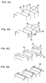
- cuts 33 are made from the edges of the end portions of the corrugated plate on one side along the creases at the corners defined by shorter sides 30 and the longer sides 31 in advance.
- the opposed longer sides 31 are folded into the shape of a roof so that the extremities thereof are brought closer, and simultaneously, the shorter sides 30 are bent and flattened out toward the folded opposed longer sides 31 as if they enfold the bent opposed longer sides 31.
- they are flattening out so that the end surfaces of the longer sides 31 and of the shorter sides 30 are aligned and overlapped with each other, and that the bent contact surfaces of the extremities of the longer sides 31 are formed to be upright.
- the end portions of the corrugated plate 35 formed by the shorter sides 30 and the longer sides 31 may be formed into substantially T-shape.
- the minute gap formed between the corrugated plate 1 and the base plate 2, and between the corrugated plate 1 and the cover plate 4 may be hermetically sealed by the use of adhesive agent or sealing material, or may be joined by brazing using brazing material formed in the corrugated plate.
- the shape described in conjunction with the second embodiment referring to Fig. 4 may be applied to the heat exchanger according to the sixth embodiment of the invention.
- the shape described in conjunction with the fifth embodiment referring to Figs. 5A to 5C may be applied as a method of forming the end portions of the corrugated plate into the roof shape to bring the extremities closer.
- the shape described in conjunction with the first embodiment is applied to the heat exchanger according to the seventh embodiment of the invention.
- the corrugated plate having the end portions formed in the roof shape, and the extremities being brought closer and processed.
- the heat exchanger uses a cladding plate with brazing material formed on both of the surfaces of the core material as material of the corrugated plate.
- cuts 43 are made on the shorter sides 40 from the upper edges of the end portions of the corrugated plate on one side in advance.
- the cuts 43 are made on the shorter sides 40 so as to leave margins 44 not less than several mm in width on both sides closer to the longer sides 41.
- the cuts 43 are made so as to leave margins 44 for brazing the end portions of the corrugated plate to the cover plate or to the base plate.
- the margins 44 may have any width, for example, approximately 1 mm, as far as it can be used for brazing.
- the cuts 43 on the shorter sides 40 are expanded outwardly, and then the expanded margins 44 are brought into contact with the adjacent margins respectively so that the end surfaces of the extremities of the margins 44 are aligned and overlapped with each other.
- the bent contact surfaces of the extremities of the margins 44 are preferably formed to be upright.
- the extremities of the opposed longer sides 41 are brought closer into the roof shape, and simultaneously, the shorter sides 42 are bent and flattened out toward the folded opposed longer sides 41 as if they enfold the bent opposed longer sides 41. As shown in Fig. 6D, they are flattened out so that the end surfaces of the longer sides 41 and of the shorter sides 42 are aligned and overlapped with each other.
- the bent contact surfaces of the extremities of the longer sides 41 are preferably formed to be upright.
- the end portions 45 of the corrugated plate 45 formed by the shorter sides 40 and the longer sides 41 may be formed into substantially T-shape.
- the minute gaps formed between the corrugated plate 1 and the base plate 2, and the corrugated plate 1 and the cover plate 4 may be hermetically sealed by the use of adhesive agent or sealing material, or may be joined by brazing using brazing material in the corrugated plate.
- the shape described in conjunction with the second embodiment referring to Fig. 4 may be applied to the heat exchanger according to the eighth embodiment of the invention.
- the shape described in conjunction with the seventh embodiment referring to Figs. 6A to 6D may be applied as a method of forming the end portions of the corrugated plate into the roof shape to bring the extremities closer.
- the flow paths A and the flow paths B are alternately disposed along the lateral direction of the corrugated plate described above, and the extent of turbulent flow of fluid that is generated in the vicinity of the inlet ports is alleviated by the shape of the end portions hermetically sealed by providing two corresponding slant surfaces.
- the aforementioned end portions sealed by providing two corresponding slant surfaces are further sealed hermetically by brazing.
- the corrugated plate is formed of cladding material comprising core material and brazing material formed on both surfaces thereof, and the corrugated plate and the base plate, and the corrugated plate and the cover plate are respectively joined by brazing with brazing material of the corrugated plate.
- corrugated plate and the base plate, and the corrugated plate and the cover plate, which are brazed and joined, are further joined by adhesive agent or sealing material.
- the end portions hermetically sealed by providing two corresponding slant surfaces are provided with vertical surfaces as margins for brazing, and hermetically sealed by brazing the vertical surfaces.
- the invention will produce its effects by being applied to the given heat exchanger performing heat exchange via the corrugated plate.
- a heat exchanger having a construction shown in Fig. 1 was manufactured.
- a corrugated plate 1 of cladding plate of 0.5 mm in thickness including brazing material of JIS4045 alloyed metal on both of the surfaces of the core material of JIS3003 alloyed metal was used as a corrugated plate 1.
- the end portions 10 which were to be the upper end portions of the flow paths 3(A) and the end portions which were to be the lower end portions of the flow paths 6(B) were processed to be brought closer into the shape of a gable roof in advance by the method described in conjunction with Figs. 2A to 2C, and joined by brazing by filling brazing material in the minute gaps at the extremities thereof in the subsequent heating process.
- the corrugated plate 1 and the base plate 2, and the corrugated plate 1 and the body portion of the cover plate 5 are respectively joined by adhesive agent.
- a heat exchanger having the same construction as the one shown in Fig. 1 other than that the corrugated plate 1 and the base plate 2, and the corrugated plate 1 and the body portion of the cover plate 5 were brazed by brazing material in the corrugated plate was manufactured.
- the heat exchanger having the same construction as the one shown in Fig. 1 other than that the shape of the end portion of the corrugated plate is formed continuously without any cut into T-shape by the method shown in Figs. 6A to 6D was manufactured by the same method as that in Example 2.
- a corrugated plate formed of JIS3003 alloyed metal plate of 0.5 mm in thickness was used as a corrugated plate 1.
- the end portions 10 which were to be upper end portions of the flow paths 3(A) and the end portions which were to be the lower end portions of the flow paths 6(B) were processed to be brought closer into the shape of a gable roof in advance by the method described in conjunction with Figs. 2A to 2C, and hermetically sealed by filling sealing material 23 in the minute gaps at the extremities thereof.
- the corrugated plate 1 and the base plate 2, and the corrugated plate 1 and the body portion 5 of the cover plate were joined by adhesive agent.
- a heat exchanger having a construction shown in Fig. 1 other than the points described above was manufactured.
- a heat exchanger having a construction shown in Fig. 1 other than that the upper end portions of the flow paths 3(A) and the lower end portions of the flow paths 6(B) were hermetically sealed by filling rubber material 26 and sealing material 23 without being processed to be formed into the shape of a gable roof was manufactured by the same method as that in the first comparative example.
- Fig. 7A a schematic plan view showing the upper end portions of the flow paths A in the first embodiment is shown.
- Fig. 7B shows the second embodiment
- Fig. 7C shows the third embodiment
- Fig. 7D shows the first comparative example
- Fig. 7E shows the second comparative example.
- the extremity 11 of the end portions 10 of the corrugated plate formed into the shape of a gable roof are joined and hermetically sealed by brazing material 25.
- the corrugated plate 1 and the base plate, and the corrugated plate 1 and the cover plate 4 are joined respectively by brazing.
- the extremity 11 of the end portions 10 of the corrugated plate formed into the shape of a gable roof were hermetically sealed with sealing material 23.
- the upper end portions are not formed into the roof shape, but hermetically sealed as is with sealing material 23, or with sealing material 23 and rubber material 26.
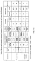
- the respective heat exchangers manufactured in the first to third examples of the invention and in the first and second comparative examples were inspected for their hermeticity of the hermetically sealed end portions of the corrugated plates. Those having good hermeticity were inspected for the pressures loss. The method of measuring the hermeticity will be described referring to Fig. 8. In a first place, the inlet port for fluid A of the heat exchanger is hermetically sealed and a hose 18 is attached to the outlet port 8 for fluid A in the water-tight state.
- example No.3 of the invention which has no cut at the extremities of the corrugated plate and formed into a continuous T-shape was superior in hermeticity. Since the end portions of the corrugated plate were formed into the shape of a gable roof, the extent of turbulent flow of fluid was alleviated and pressure losses were reduced. Examples No. 2 and No. 3 of the invention in which the extremities of the corrugated plate, and the corrugated plate and the base plate are brazed simultaneously were superior in hermeticity and excellent in productivity.
- the invention relates to a heat exchanger in which fluid A and fluid B are flown in the flow paths 3(A) and flow paths 6(B) formed via the corrugated plate respectively for exchanging heat between the fluid A and fluid B.
- the extremities were brought closer by forming the end portions of the corrugated plate into the shape of a gabled roof for brazing, and thus the sealing work can be performed easily and the good results of sealing may be achieved.
- the extent of turbulent flow of fluid in the vicinity of the fluid inlet ports is alleviated, and thus pressure losses of fluid is reduced thereby realizing miniaturization of the fan and saving of electricity expense. Therefore, industrially outstanding effects can be produced.
Landscapes
- Engineering & Computer Science (AREA)
- Physics & Mathematics (AREA)
- Thermal Sciences (AREA)
- Mechanical Engineering (AREA)
- General Engineering & Computer Science (AREA)
- Heat-Exchange Devices With Radiators And Conduit Assemblies (AREA)
Abstract
Description
one of upper end portions and lower end portions of said corrugated plate for forming the flow paths A, which are hermetically sealed by providing two corresponding slant surfaces, and other one of the upper end portions and lower end portions of said corrugated plate for forming the flow paths B, which are hermetically sealed by providing two corresponding slant surfaces;
inlet ports for said fluid B being provided on one end portion of the corrugated plate which is the hermetically sealed side of the flow paths A, and inlet ports for said fluid A being provided on other end portion of the corrugated plate which is the hermetically sealed side of the flow paths B;
outlet ports for said fluid A and for said fluid B respectively being provided on opposite sides of said inlet ports for fluid A and fluid B,
wherein heat is exchanged between fluid A and fluid B via the corrugated plate by supplying fluid A into the plurality of said flow paths A and supplying fluid B into the plurality of said flow paths B respectively from said inlet ports thus constructed toward said outlet ports.
two types of fluid flow paths A and B defined by said corrugated plate, said base plate, and said cover plate along a longitudinal direction of said corrugated plate, said two types of flow paths comprising a plurality of flow paths A defined by said one of surfaces of said corrugated plate and said base plate, and said plurality of flow paths B defined by other surface of said corrugated plate and said cover plate, said plurality of flow paths A and said plurality of flow paths B being formed separately from each other;
upper end portion and lower end portion of said corrugated plate forming the flow paths A or B, which are hermetically sealed by providing two corresponding slant surfaces;
inlet ports provided on said base plate or said cover plate forming said flow paths A or said flow paths B, upper end portions and lower end portions of which are hermetically sealed, and outlet ports provided opposite side of said inlet ports;
inlet ports provided on one end of said flow paths A or said flow paths B, upper end portions and lower end portions of which are not hermetically sealed, and outlet ports provided on opposite side of said inlet ports,
wherein heat is exchanged between fluid A and fluid B via the corrugated plate by supplying fluid A into the plurality of said flow paths A and supplying fluid B into the plurality of said flow paths B respectively from said inlet ports thus constructed toward said outlet ports.
two types of fluid flow paths A and B defined by said corrugated plate, said base plate, and said cover plate along a longitudinal direction of said corrugated plate, said two types of fluid flow paths comprising a plurality of flow paths A defined by said one of surfaces of said corrugated plate and said base plate, and said plurality of flow paths B defined by other surface of said corrugated plate and said cover plate, said plurality of flow paths A and said plurality of flow paths B being formed separately from each other;
one end portion of the upper end portion or the lower end portion of said corrugated plate forming the flow path A and other end portion of the upper end portion or the lower end portion of said corrugated plate forming the flow path B, which are hermetically sealed by providing two corresponding slant surfaces, respectively;
outlet ports for said fluid B being provided on one end portion of the corrugated plate which is the hermetically sealed side of the flow paths A, and outlet ports for said fluid A being provided on the other end portion of the corrugated plate which is the hermetically sealed side of the flow paths B;
inlet ports for said fluid A or inlet ports for said fluid B being provided on said base plate or said cover plate forming said flow paths A and said flow paths B,
wherein heat is exchanged between fluid A and fluid B via the corrugated plate by supplying fluid A into the plurality of said flow paths A and supplying fluid B into the plurality of said flow paths B respectively from thus constructed said inlet ports toward said outlet ports.
Claims (17)
- A heat exchanger comprising:a corrugated plate (1);a base plate (2);a cover plate (4);a plurality of flow paths A and a plurality of flow paths B defined by the corrugated plate (1), the base plate (2) and the cover plate (4) disposed so as to interpose the corrugated plate (1) therebetween; andthe plurality of flow paths A and the plurality of flow paths B being alternately and adjacently arranged on both sides of the corrugated plate (1) for exchanging heat between fluid A and fluid B via the corrugated plate (1) by supplying fluid A through a plurality of flow paths A and fluid B through a plurality of flow paths B,wherein at least one of the end portions of the plurality of flow paths is hermetically sealed by making partial cuts (13) at the end portions (10) of the corrugated plate (1) and/or folding a part of the end portions (10) of the corrugated plate (1), bending opposing ends (14, 16) of the corrugated plate (1) so as to form them respectively into a shape of a gable roof, bringing at least a part of the ends (14, 15, 16) of the corrugated plate (1) into contact with each other, and brazing portions in contact, so that openings of one of the flow paths A and the flow paths B are hermetically sealed for allowing only one of the fluids to flow in/out at each end of the corrugated plate (1).
- The heat exchanger according to Claim 1,
wherein the cover plate (4) and/or the base plate (2) are hermetically sealed with the end portions of the corrugated plate (1) by making cuts (13) at the end portions of the corrugated plate (1) to leave margins so as to be capable of brazing either on the cover plate (4) or on the base plate (2), and brazing the margins. - The heat exchanger according to Claim 1 or 2,
wherein the corrugated plate (1) is brazed to the base plate (2) and/or the cover plate (4) by the brazing material in a clad corrugated plate, and the flow paths A are completely divided off the flow paths B. - The heat exchanger according to any of Claims 1 to 3,
wherein the corrugated plate (1) comprises a cladding plate including a core material and a brazing material formed on one side or both sides of the core material. - A heat exchanger comprising:a corrugated plate (1);a base plate (2) joined on one of surfaces of the corrugated plate (1);a cover plate (4) joined on other surfaces of the corrugated plate (1);two types of fluid flow paths A and B defined by the corrugated plate (1), the base plate (2), and the cover plate (4) along a longitudinal direction of the corrugated plate (1), the two types of fluid flow paths comprising a plurality of flow paths A defined by the one of surfaces of the corrugated plate (1) and the base plate (2), and the plurality of flow paths B defined by other surfaces of the corrugated plate (1) and the cover plate (4), the plurality of flow paths A and the plurality of flow paths B being formed separately from each other;one of upper end portions and lower end portions of the corrugated plate (1) for forming the flow paths A, which are hermetically sealed by providing two corresponding slant surfaces, and other one of the upper end portions and lower end portions of the corrugated plate (1) for forming the flow paths B, which are hermetically sealed by providing two corresponding slant surfaces;inlet ports (29) for the fluid B being provided on one end portion of the corrugated plate (1) which is the hermetically sealed side of the flow paths A, and inlet ports (28) for the fluid A being provided on the other end portion of the corrugated plate (1) which is the hermetically sealed side of the flow paths B;outlet ports (8, 9) for the fluid A and for the fluid B, respectively, being provided on opposite sides of the inlet ports (28, 29) for fluid A and fluid B,wherein heat is exchanged between fluid A and fluid B via the corrugated plate (1) by supplying fluid A into the plurality of the flow paths A and supplying fluid B into the plurality of the flow paths B, respectively, from the inlet ports (28, 29) toward the outlet ports (8, 9).
- The heat exchanger according to Claim 5,
wherein the flow paths A and the flow paths B are alternately disposed along a lateral direction of the corrugated plate (1), and an extent of turbulent flow of fluid that is generated in the vicinity of the inlet ports (28, 29) is alleviated by a shape of the end portions hermetically sealed by providing the two corresponding slant surfaces. - A heat exchanger comprising:a corrugated plate (1);a base plate (2) joined on one of surfaces of the corrugated plate (1);a cover plate (4) joined on other surfaces of the corrugated plate (1);two types of fluid flow paths A and B defined by the corrugated plate (1), the base plate (2), and the cover plate (4) along a longitudinal direction of the corrugated plate (1), the two types of flow paths comprising a plurality of flow paths A defined by the one of surfaces of the corrugated plate (1) and the base plate (2), and the plurality of flow paths B defined by other surfaces of the corrugated plate (1) and the cover plate (4), the plurality of flow paths A and the plurality of flow paths B being formed separately from each other;upper end portion and lower end portion of the corrugated plate (1) forming the flow paths A or B, which are hermetically sealed by providing two corresponding slant surfaces;inlet ports (28, 29) provided on the base plate (2) or the cover plate (4) forming the flow paths A or the flow paths B, upper end portions and lower end portions of which are hermetically sealed, and outlet ports (8, 9) provided at the opposite side of the inlet ports;inlet ports (28, 29) provided on one end of the flow paths A or the flow paths B, upper end portions and lower end portions of which are not hermetically sealed, and outlet ports (8, 9) provided on the opposite the side of the inlet ports (28, 29);wherein heat is exchanged between fluid A and fluid B via the corrugated plate (1) by supplying fluid A into the plurality of the flow paths A and supplying fluid B into the plurality of the flow paths B, respectively, from the inlet ports (28, 29) thus constructed toward the outlet ports (8, 9).
- The heat exchanger according to Claim 7,
wherein the fluid A and the fluid B flow in opposite directions. - A heat exchanger comprising:a corrugated plate (1);a base plate (2) joined on one of surfaces of the corrugated plate (1);a cover plate (4) joined on other surfaces of the corrugated plate (1);two types of fluid flow paths A and B defined by the corrugated plate (1), the base plate (2), and the cover plate (4) along a longitudinal direction of the corrugated plate (1), the two types of fluid flow paths comprising a plurality of flow paths A defined by the one of surfaces of the corrugated plate (1) and the base plate (2), and the plurality of flow paths B defined by other surfaces of the corrugated plate (1) and the cover plate (2), the plurality of flow paths A and the plurality of flow paths B being formed separately from each other;one end portion of the upper end portion or the lower end portion of the corrugated plate (1) forming the flow paths A and the other end portion of the upper end portion or the lower end portion of the corrugated plate (1) forming the flow paths B, which are hermetically sealed by providing two corresponding slant surfaces, respectively;outlet ports (9) for the fluid B being provided on one end portion of the corrugated plate (1) which is the hermetically sealed side of the flow paths A, and outlet ports (8) for the fluid A being provided on the other end portion of the corrugated plate (1) which is the hermetically sealed side of the flow paths B;inlet ports (28) for the fluid A or inlet ports (29) for the fluid B being provided on the base plate (2) or the cover plate (4) forming the flow paths A and the flow paths B;wherein heat is exchanged between fluid A and fluid B via the corrugated plate (1) by supplying fluid A into the plurality of the flow paths A and supplying fluid B into the plurality of the flow paths B, respectively, from the thus constructed inlet ports (28, 29) toward the outlet ports (8, 9).
- The heat exchanger according to any one of claims 5 to 9,
wherein the end portions with the two corresponding slant surfaces provided are hermetically sealed by brazing. - The heat exchanger according to Claim 10,
wherein the end portions hermetically sealed by providing the two corresponding slant surfaces are provided with vertical surfaces as margins for brazing, and hermetically sealed by brazing the vertical surfaces. - The heat exchanger according to any one of Claims 5 to 9,
wherein the corrugated plate (1) is formed of cladding material comprising a core material and brazing material formed on one or both surfaces of the core material, and the corrugated plate (1) and the base plate (2), as well as/or the corrugated plate (1) and the cover plate (4) are respectively joined by brazing with the brazing material of the corrugated plate (1). - The heat exchanger according to Claim 12,
wherein the corrugated plate (1) and the base plate (2), and the corrugated plate (1) and the cover plate (4), which are brazed and joined, are further joined by an adhesive agent or sealing material. - The heat exchanger according to any one of Claims 5 to 9,
wherein the cover plate (4) and/or the base plate (2) are hermetically sealed with the end portions of the corrugated plate (1) by making cuts (13, 33) at the end portions of the corrugated plate (1) to leave margins so as to be capable of brazing either with the cover plate (4) or with the base plate (2), and brazing the margins. - The heat exchanger according to Claim 14,
wherein the corrugated plate (1) comprises a cladding material including a core material and brazing material formed on one or both surfaces of the core material. - The heat exchanger according to Claim 14 or 15,
wherein the corrugated plate (1) includes margins for brazing. - The heat exchanger according to any of Claims 14 to 16,
wherein the corrugated plate (1) and the base plate (2), and the corrugated plate (1) and the cover plate (4), which are brazed and joined, are further joined by an adhesive agent or sealing material.
Applications Claiming Priority (4)
| Application Number | Priority Date | Filing Date | Title |
|---|---|---|---|
| JP2001119107 | 2001-04-18 | ||
| JP2001119107 | 2001-04-18 | ||
| JP2002041564A JP2003004393A (en) | 2001-04-18 | 2002-02-19 | Heat exchanger |
| JP2002041564 | 2002-02-19 |
Publications (2)
| Publication Number | Publication Date |
|---|---|
| EP1251325A2 true EP1251325A2 (en) | 2002-10-23 |
| EP1251325A3 EP1251325A3 (en) | 2004-07-28 |
Family
ID=26613748
Family Applications (1)
| Application Number | Title | Priority Date | Filing Date |
|---|---|---|---|
| EP02008598A Withdrawn EP1251325A3 (en) | 2001-04-18 | 2002-04-16 | Heat exchanger |
Country Status (4)
| Country | Link |
|---|---|
| US (1) | US20020170706A1 (en) |
| EP (1) | EP1251325A3 (en) |
| JP (1) | JP2003004393A (en) |
| CN (1) | CN1381705A (en) |
Cited By (7)
| Publication number | Priority date | Publication date | Assignee | Title |
|---|---|---|---|---|
| EP1491838A3 (en) * | 2003-06-26 | 2005-11-16 | Tellabs Petaluma, Inc. | Heat exchanger and a method of forming the heat exchanger |
| US7011148B1 (en) | 2003-10-23 | 2006-03-14 | Tellabs Petaluma, Inc. | Heat exchanger with increased heat transfer efficiency and a low-cost method of forming the heat exchanger |
| WO2012062430A1 (en) * | 2010-11-08 | 2012-05-18 | Nft Nanofiltertechnik Gesellschaft Mit Beschränkter Haftung | Heat exchanger folded from a single metal sheet and having two separate chambers |
| DE102011077633A1 (en) * | 2011-06-16 | 2012-12-20 | Behr Gmbh & Co. Kg | Heat exchanger, particularly for motor vehicle, has heat exchanger block provided with meander-shaped base body, where two flow channels for two fluids are provided in meander-shaped base body, and front ends of adjacent walls are sealed |
| CN104279892A (en) * | 2013-07-11 | 2015-01-14 | 株式会社田洼精密机械制造厂 | Heat exchanger |
| US9297588B2 (en) | 2010-11-29 | 2016-03-29 | Takubo Machine Works Co., Ltd | Heat exchanger |
| DE102016015125A1 (en) * | 2016-12-19 | 2018-06-21 | Menk Apparatebau Gmbh | Slat arrangement and heat exchanger |
Families Citing this family (9)
| Publication number | Priority date | Publication date | Assignee | Title |
|---|---|---|---|---|
| JP2006118785A (en) * | 2004-10-21 | 2006-05-11 | Usui Kokusai Sangyo Kaisha Ltd | Heat exchanger |
| EP2113278B1 (en) * | 2007-05-21 | 2012-08-15 | Covidien AG | Medical heat and moisture exchanger (HME) |
| JP5247111B2 (en) * | 2007-10-11 | 2013-07-24 | 古河スカイ株式会社 | Heat exchanger |
| FR2980837B1 (en) * | 2011-10-04 | 2015-06-26 | Valeo Systemes Thermiques | HEAT EXCHANGER WITH STACKED PLATES. |
| JP2015025626A (en) * | 2013-07-26 | 2015-02-05 | アイシン精機株式会社 | Heat exchanger |
| CN104075593B (en) * | 2014-06-10 | 2016-08-24 | 佛山市科蓝环保科技股份有限公司 | A kind of alternating expression heat exchanger |
| KR102236771B1 (en) * | 2016-12-02 | 2021-04-06 | 삼성전자주식회사 | Outdoor display apparatus |
| CN108335865A (en) * | 2018-04-08 | 2018-07-27 | 上海置信电气非晶有限公司 | A kind of fuel tank corrugate fin group and its welding method, corrugated tank of transformer |
| CN109482737A (en) * | 2018-11-30 | 2019-03-19 | 宁波凯荣船用机械有限公司 | Film-type liquefied natural gas cargo tank maintenance system stainless steel wave card nut cap makes tooling and manufacture craft |
Family Cites Families (9)
| Publication number | Priority date | Publication date | Assignee | Title |
|---|---|---|---|---|
| US1473595A (en) * | 1920-06-02 | 1923-11-06 | Pittsburgh Transformer Co | Tank structure |
| US1444480A (en) * | 1920-11-16 | 1923-02-06 | Gen Electric | Casing for electrical apparatus |
| BE459063A (en) * | 1945-06-21 | |||
| US2953110A (en) * | 1954-01-22 | 1960-09-20 | W J Fraser & Co Ltd | Reciprocally folded sheet metal structures |
| SE352724B (en) * | 1969-11-10 | 1973-01-08 | Thermovatic Jenssen S | |
| US3829945A (en) * | 1973-07-11 | 1974-08-20 | Motoren Werke Mannheim Ag | Method of producing a heat exchanger |
| US4384611A (en) * | 1978-05-15 | 1983-05-24 | Hxk Inc. | Heat exchanger |
| US4343355A (en) * | 1980-01-14 | 1982-08-10 | Caterpillar Tractor Co. | Low stress heat exchanger and method of making the same |
| JPS57142493A (en) * | 1981-02-27 | 1982-09-03 | Nippon Denso Co Ltd | Aluminum heat exchanger |
-
2002
- 2002-02-19 JP JP2002041564A patent/JP2003004393A/en active Pending
- 2002-03-28 US US10/113,920 patent/US20020170706A1/en not_active Abandoned
- 2002-04-16 EP EP02008598A patent/EP1251325A3/en not_active Withdrawn
- 2002-04-18 CN CN02105592A patent/CN1381705A/en active Pending
Cited By (11)
| Publication number | Priority date | Publication date | Assignee | Title |
|---|---|---|---|---|
| EP1491838A3 (en) * | 2003-06-26 | 2005-11-16 | Tellabs Petaluma, Inc. | Heat exchanger and a method of forming the heat exchanger |
| US7108052B2 (en) | 2003-06-26 | 2006-09-19 | Tellabs Petaluma, Inc. | Low-cost method of forming a heat exchanger with an increased heat transfer efficiency |
| US7011148B1 (en) | 2003-10-23 | 2006-03-14 | Tellabs Petaluma, Inc. | Heat exchanger with increased heat transfer efficiency and a low-cost method of forming the heat exchanger |
| WO2012062430A1 (en) * | 2010-11-08 | 2012-05-18 | Nft Nanofiltertechnik Gesellschaft Mit Beschränkter Haftung | Heat exchanger folded from a single metal sheet and having two separate chambers |
| US9297588B2 (en) | 2010-11-29 | 2016-03-29 | Takubo Machine Works Co., Ltd | Heat exchanger |
| DE102011077633A1 (en) * | 2011-06-16 | 2012-12-20 | Behr Gmbh & Co. Kg | Heat exchanger, particularly for motor vehicle, has heat exchanger block provided with meander-shaped base body, where two flow channels for two fluids are provided in meander-shaped base body, and front ends of adjacent walls are sealed |
| CN104279892A (en) * | 2013-07-11 | 2015-01-14 | 株式会社田洼精密机械制造厂 | Heat exchanger |
| EP2824410A1 (en) * | 2013-07-11 | 2015-01-14 | Takubo Machine Works Co., Ltd. | Heat exchanger |
| CN104279892B (en) * | 2013-07-11 | 2016-08-24 | 株式会社田洼精密机械制造厂 | Heat exchanger |
| US10054370B2 (en) | 2013-07-11 | 2018-08-21 | Takubo Machine Works Co., Ltd. | Heat exchanger |
| DE102016015125A1 (en) * | 2016-12-19 | 2018-06-21 | Menk Apparatebau Gmbh | Slat arrangement and heat exchanger |
Also Published As
| Publication number | Publication date |
|---|---|
| US20020170706A1 (en) | 2002-11-21 |
| JP2003004393A (en) | 2003-01-08 |
| EP1251325A3 (en) | 2004-07-28 |
| CN1381705A (en) | 2002-11-27 |
Similar Documents
| Publication | Publication Date | Title |
|---|---|---|
| US20020170706A1 (en) | Heat exchanger | |
| EP0704667B1 (en) | Heat-exchanging conduit tubes for laminated heat exchanger and method for producing same | |
| KR100274586B1 (en) | Heat exchanger | |
| KR0122533B1 (en) | Heat exchanger tube and manufacture to decrease welding fault with head pipe | |
| EP1158260B1 (en) | Heat exchanger, method of manufacturing the heat exchanger, and method of manufacturing tube for heat exchange | |
| US5685075A (en) | Method for brazing flat tubes of laminated heat exchanger | |
| EP1712862A2 (en) | Fabricated, brazed metal heat exchanger tube manufacture | |
| JPH08200977A (en) | Flat tube for heat exchanger and manufacturing method thereof | |
| CN103502761A (en) | A method of producing a heat exchanger and a heat exchanger | |
| US8726507B2 (en) | Method for manufacturing a heat exchanger and exchanger obtained by the method | |
| JPH02154992A (en) | Heat exchanger employing flat tube | |
| JP2932846B2 (en) | Stacked heat exchanger and method of manufacturing the same | |
| CN110670799A (en) | Structural plate with cavity and manufacturing method thereof | |
| JP2008516177A (en) | Flat tube for heat exchanger | |
| JP2009008347A (en) | Heat exchanger | |
| CN117381269A (en) | Flat tube, heat exchanger with same and forming method of flat tube | |
| JP3756641B2 (en) | Tube for heat exchanger and manufacturing method thereof | |
| JP3912889B2 (en) | Tube for heat exchanger and manufacturing method thereof | |
| CN108267033A (en) | A kind of integral braze-welded plate-fin heat exchanger | |
| CN101089535A (en) | End face forming sealed plate heat exchanger | |
| KR100254321B1 (en) | Heat exchanger tube and its manufacturing method | |
| CN223910098U (en) | Microchannel plate-fin heat exchanger | |
| CN112815748A (en) | Split type interface brazing plate heat exchanger | |
| JP2007147173A (en) | Heat exchanger and its manufacturing method | |
| JPH08233476A (en) | Heat exchanger |
Legal Events
| Date | Code | Title | Description |
|---|---|---|---|
| PUAI | Public reference made under article 153(3) epc to a published international application that has entered the european phase |
Free format text: ORIGINAL CODE: 0009012 |
|
| 17P | Request for examination filed |
Effective date: 20020416 |
|
| AK | Designated contracting states |
Kind code of ref document: A2 Designated state(s): AT BE CH CY DE DK ES FI FR GB GR IE IT LI LU MC NL PT SE TR |
|
| AX | Request for extension of the european patent |
Free format text: AL;LT;LV;MK;RO;SI |
|
| PUAL | Search report despatched |
Free format text: ORIGINAL CODE: 0009013 |
|
| AK | Designated contracting states |
Kind code of ref document: A3 Designated state(s): AT BE CH CY DE DK ES FI FR GB GR IE IT LI LU MC NL PT SE TR |
|
| AX | Request for extension of the european patent |
Extension state: AL LT LV MK RO SI |
|
| AKX | Designation fees paid |
Designated state(s): DE FI FR GB SE |
|
| STAA | Information on the status of an ep patent application or granted ep patent |
Free format text: STATUS: THE APPLICATION HAS BEEN WITHDRAWN |
|
| 18W | Application withdrawn |
Effective date: 20060309 |