EP1251323A1 - Condenser - Google Patents
Condenser Download PDFInfo
- Publication number
- EP1251323A1 EP1251323A1 EP01946932A EP01946932A EP1251323A1 EP 1251323 A1 EP1251323 A1 EP 1251323A1 EP 01946932 A EP01946932 A EP 01946932A EP 01946932 A EP01946932 A EP 01946932A EP 1251323 A1 EP1251323 A1 EP 1251323A1
- Authority
- EP
- European Patent Office
- Prior art keywords
- vapor
- passages
- cooling section
- tubular portion
- dropped
- Prior art date
- Legal status (The legal status is an assumption and is not a legal conclusion. Google has not performed a legal analysis and makes no representation as to the accuracy of the status listed.)
- Withdrawn
Links
- 238000001816 cooling Methods 0.000 claims abstract description 48
- 238000011084 recovery Methods 0.000 claims abstract description 26
- 239000007791 liquid phase Substances 0.000 claims description 11
- 239000012071 phase Substances 0.000 claims description 5
- XLYOFNOQVPJJNP-UHFFFAOYSA-N water Substances O XLYOFNOQVPJJNP-UHFFFAOYSA-N 0.000 abstract description 29
- 230000002093 peripheral effect Effects 0.000 description 18
- 238000004891 communication Methods 0.000 description 11
- 238000005219 brazing Methods 0.000 description 7
- UFHFLCQGNIYNRP-UHFFFAOYSA-N Hydrogen Chemical compound [H][H] UFHFLCQGNIYNRP-UHFFFAOYSA-N 0.000 description 6
- 239000001257 hydrogen Substances 0.000 description 6
- 229910052739 hydrogen Inorganic materials 0.000 description 6
- 238000009957 hemming Methods 0.000 description 5
- 229910052782 aluminium Inorganic materials 0.000 description 4
- XAGFODPZIPBFFR-UHFFFAOYSA-N aluminium Chemical compound [Al] XAGFODPZIPBFFR-UHFFFAOYSA-N 0.000 description 4
- 238000010168 coupling process Methods 0.000 description 4
- 238000005859 coupling reaction Methods 0.000 description 4
- 238000005192 partition Methods 0.000 description 4
- 230000008878 coupling Effects 0.000 description 3
- 230000000694 effects Effects 0.000 description 3
- 239000000463 material Substances 0.000 description 3
- 230000009467 reduction Effects 0.000 description 3
- 230000000630 rising effect Effects 0.000 description 3
- 238000009833 condensation Methods 0.000 description 2
- 230000005494 condensation Effects 0.000 description 2
- 239000002826 coolant Substances 0.000 description 2
- 230000003247 decreasing effect Effects 0.000 description 2
- 239000007789 gas Substances 0.000 description 2
- 239000007788 liquid Substances 0.000 description 2
- 238000007789 sealing Methods 0.000 description 2
- 229910000838 Al alloy Inorganic materials 0.000 description 1
- 230000009471 action Effects 0.000 description 1
- 238000006243 chemical reaction Methods 0.000 description 1
- 238000002485 combustion reaction Methods 0.000 description 1
- 238000007599 discharging Methods 0.000 description 1
- -1 e.g. Substances 0.000 description 1
- 238000003780 insertion Methods 0.000 description 1
- 230000037431 insertion Effects 0.000 description 1
- 230000007246 mechanism Effects 0.000 description 1
- 239000007769 metal material Substances 0.000 description 1
- 238000004064 recycling Methods 0.000 description 1
- 230000007480 spreading Effects 0.000 description 1
- 239000010935 stainless steel Substances 0.000 description 1
- 229910001220 stainless steel Inorganic materials 0.000 description 1
- 238000004381 surface treatment Methods 0.000 description 1
Images




Classifications
-
- F—MECHANICAL ENGINEERING; LIGHTING; HEATING; WEAPONS; BLASTING
- F28—HEAT EXCHANGE IN GENERAL
- F28B—STEAM OR VAPOUR CONDENSERS
- F28B1/00—Condensers in which the steam or vapour is separate from the cooling medium by walls, e.g. surface condenser
- F28B1/06—Condensers in which the steam or vapour is separate from the cooling medium by walls, e.g. surface condenser using air or other gas as the cooling medium
-
- F—MECHANICAL ENGINEERING; LIGHTING; HEATING; WEAPONS; BLASTING
- F28—HEAT EXCHANGE IN GENERAL
- F28B—STEAM OR VAPOUR CONDENSERS
- F28B9/00—Auxiliary systems, arrangements, or devices
- F28B9/08—Auxiliary systems, arrangements, or devices for collecting and removing condensate
-
- F—MECHANICAL ENGINEERING; LIGHTING; HEATING; WEAPONS; BLASTING
- F28—HEAT EXCHANGE IN GENERAL
- F28D—HEAT-EXCHANGE APPARATUS, NOT PROVIDED FOR IN ANOTHER SUBCLASS, IN WHICH THE HEAT-EXCHANGE MEDIA DO NOT COME INTO DIRECT CONTACT
- F28D9/00—Heat-exchange apparatus having stationary plate-like or laminated conduit assemblies for both heat-exchange media, the media being in contact with different sides of a conduit wall
- F28D9/0012—Heat-exchange apparatus having stationary plate-like or laminated conduit assemblies for both heat-exchange media, the media being in contact with different sides of a conduit wall the apparatus having an annular form
-
- F—MECHANICAL ENGINEERING; LIGHTING; HEATING; WEAPONS; BLASTING
- F28—HEAT EXCHANGE IN GENERAL
- F28D—HEAT-EXCHANGE APPARATUS, NOT PROVIDED FOR IN ANOTHER SUBCLASS, IN WHICH THE HEAT-EXCHANGE MEDIA DO NOT COME INTO DIRECT CONTACT
- F28D9/00—Heat-exchange apparatus having stationary plate-like or laminated conduit assemblies for both heat-exchange media, the media being in contact with different sides of a conduit wall
- F28D9/0031—Heat-exchange apparatus having stationary plate-like or laminated conduit assemblies for both heat-exchange media, the media being in contact with different sides of a conduit wall the conduits for one heat-exchange medium being formed by paired plates touching each other
- F28D9/0043—Heat-exchange apparatus having stationary plate-like or laminated conduit assemblies for both heat-exchange media, the media being in contact with different sides of a conduit wall the conduits for one heat-exchange medium being formed by paired plates touching each other the plates having openings therein for circulation of at least one heat-exchange medium from one conduit to another
- F28D9/005—Heat-exchange apparatus having stationary plate-like or laminated conduit assemblies for both heat-exchange media, the media being in contact with different sides of a conduit wall the conduits for one heat-exchange medium being formed by paired plates touching each other the plates having openings therein for circulation of at least one heat-exchange medium from one conduit to another the plates having openings therein for both heat-exchange media
Definitions
- the present invention relates to a condenser for converting an operating medium in a gas-phase state into a liquid-phase state.
- the operating medium in the liquid-phase state produced in such passages e.g., water occludes the passages due to factors such as a surface tension of the operating medium and as a result, the amount of water vapor flowing in the cooling section is reduced, resulting in a reduction in condensing performance.
- a condenser comprising a cooling section having a plurality of operating medium passages to convert an operating medium in a gas-phase state into a liquid-phase state, a suction means for drawing the operating medium in the liquid-phase state produced in the operating medium passages out of the passages, and a recovery section for receiving the operating medium drawn out in the liquid-phase state.
- the operating medium in the liquid-phase state can be forcibly discharged out of the passages and hence, the amount of operating medium flowing in the gas-phase state in the cooling section can be maintained, whereby the intrinsic condensing performance can be ensured.
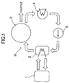
- Fig.1 is an illustration for explaining a Ranking cycle system
- Fig.2 is a vertical sectional front view of a condenser
- Fig.3 is an enlarged view of essential portions of Fig.2
- Fig.4 is a view for explaining one example of a structure of a cooling section and a recovery section, and corresponds to a sectional view taken along a line 4-4 in Fig.5
- Fig.5 is a sectional view taken along a line 5-5 in Fig.2 and corresponds to a sectional view taken along a line 5-5 in Fig.4
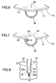
- Fig.6 is a sectional view showing an annular panel in a state in which a portion thereof has been fitted in a groove in a guide tube
- Fig.7 is a sectional view showing the annular panel in a state in which a portion protruding into the guide tube has been cut away
- Fig.8 is a view taken in the direction of an arrow 8 in Fig.7
- a Rankine cycle system R shown in Fig.1 includes an evaporator 2 for generating a high-pressure water vapor (an operating medium in the gas-phase state) having a raised temperature, namely, a high-temperature and high-pressure vapor, from a high-pressure liquid, e.g., water (an operating medium in the liquid-phase state) using an exhaust gas from an internal combustion engine 1, an expander 3 for generating an output by the expansion of the high-temperature and high-pressure vapor, a condenser 4 for liquefying the vapor dropped in temperature and pressure by the expansion, namely, a dropped-temperature and dropped-pressure vapor discharged from the expander 3, thereby producing water, and a feed pump 5 for supplying water from the condenser 4 to the evaporator 2 under a pressure.
- a high-pressure water vapor an operating medium in the gas-phase state
- a high-pressure liquid e.g., water (an operating medium in the liquid-phase state)
- the expander 3 includes a substantially horizontal high-temperature and high-pressure vapor introducing pipe 7 at a center portion of one end of a casing 6 of the expander 3, and a plurality of dropped-temperature and dropped-pressure vapor outlet bores 8 in an upper portion of the other end of the casing 6.
- the expander 3 includes a substantially horizontal output shaft 9 at a center portion thereof.
- the condenser 4 is mounted to the expander 3, so that it receives the dropped-temperature and dropped-pressure vapor from each of the outlet bores 8.
- the condenser 4 includes a cylindrical housing 10, and a cooling section 12 provided within a larger-diameter tubular portion 11 of the housing 10 for converting the dropped-temperature and dropped-pressure vapor into water.
- the cooling section 12 is formed into a hollow columnar shape with a plurality of annular panel 13 made of a metal material such as a stainless steel, aluminum and the like and superposed one on another, and is provided at its center portion with a vapor introducing bore 15 provided by the bores 14 in the annular panels 13.
- the centerline of the vapor introducing bore 15 is in accord with an axis of the output shaft 9.
- An annular end plate 17 existing at one end of a tubular vapor guide 16 and a flange 18 existing around an outer periphery of the end plate 17 are opposed to an annular end face of the cooling section 12 on the side of the expander 3.
- An outer peripheral portion of the flange 18 is integral with the cooling section 12.
- a bore 19 in the end plate 17 is in accord with the vapor introducing bore 15.
- a flange 20 existing at the other end of the tubular vapor guide 16 is superposed on a flange 21 existing at one end of the larger-diameter tubular portion 11, and is secured to a flange 23 of the expander 3 by a plurality of bolts 22.
- the dropped-temperature and dropped-pressure vapor outlet bores 8 in the expander 3 face into the tubular vapor guide 16.
- the housing 10 has a split smaller-diameter tubular portion 24 disposed at the other end of the larger-diameter tubular portion 11.
- a flange 25 of the smaller-diameter tubular portion 24 is opposed to an annular end face of the cooling section 12, and an outer periphery of the smaller-diameter tubular portion 24 is integral with the cooling section 12.
- a transmitting shaft 27 is mounted to the output shaft 9 of the expander 3 through a spline-coupling portion 26.
- the transmitting shaft 27 protrudes to the outside through the vapor introducing bore 15 in the cooling section 12 and an end wall 28 of the smaller-diameter tubular portion 24, and is rotatably supported at the end wall 28 with a bearing 29 interposed therebetween.
- Two seal rings 31 are mounted to the transmitting shaft 27 for sealing the transmitting shaft 27 and a shaft insertion bore 30 provided in the end wall 28 outside the bearing 29 from each other.
- a stationary guide tube 32 extending in parallel to the transmitting shaft 27, and a recovery tube 33 which is slidably fitted in the guide tube 32 and serves as a recovery section for recovering water produced by cooling the dropped-temperature and dropped-pressure vapor.
- An end of the recovery tube 33 adjacent the expander 3 is closed, but an opposite end of the recovery tube 33 is open.
- a recovery tube detent means comprising a key 34 and a key groove 35 is provided between an inner peripheral surface of the guide tube 32 and an outer peripheral surface of the recovery tube 33.
- each of the annular panels 13 in the cooling section 12 includes a group of projections 36 formed by pressing, and a plurality of tube-shaped vapor passages (operating-medium passages) 37 are defined between a set of the two annular panels 13 by brazing the opposed groups of projections 36 on such set of the two annular panels 13 to each other.
- the peripheries of the bores 14 in such two annular panels 13 are sealed by brazing of two arcuate projections 38 with their upper portions opened, and an inlet 39 of the vapor passage 37 is defined between opposite ends of the arcuate projections 38 to communicate with an upper portion of the vapor introducing bore 15.
- Substantially entire outer peripheries of the two annular panels 13 are sealed using a combination of the hemming and the brazing, but hemmed portions 41 are separated at a lower portion and at a notch 40 located on a diameter bisecting the inlet 39.
- a peripheral portion 42 of the notch 40 is fitted into and brazed in one of a plurality of grooves 43 provided at predetermined distances in an axial direction of the guide tube 32.
- an inner peripheral surface of the notch 40 is matched to an inner peripheral surface of the guide tube 32, whereby outlets 44 of the vapor passages 37 defined by the annular panels 13 face into the guide tube 32.
- the vapor passage 37 is defined by cooperation of the one annular panel 13 and the annular end plate 17 as well as the flange 18, and at the end adjacent the smaller-diameter tubular portion 24, the vapor passage 37 is defined by cooperation of the one annular panel 13 and the flange 25 as well as a partition wall 45 on an inner peripheral side of the flange 25.
- Each of the hemmed portions 41 is fitted into corresponding one of grooves 47 in the comb-shaped distance-adjusting plate 46 extending in a direction of a generating line of the cooling section 12 (also see Fig.12).
- a plurality of the distance-adjusting plates 46 are disposed at predetermined distances in a circumferential direction of the cooling section 12.
- the vapor passages 37 comprise a single rising passage 48 extending upwards on a panel radius from the inlet 39, a plurality of branch passages 49 diverted in opposite directions from the rising passage 48 and in a circumferential direction, a plurality of downcomer passages 50 leading to lower portions of the branch passages 49, a plurality of convergent passages 51 leading to lower portions of the downcomer passages 50, and the outlets 44 where the convergent passages 51 are collected together.
- portions of the annular panels 13 hemmed over their entire outer peripheral portions, which are on the side of the convergent passages 51, are fitted into the grooves 43 in the guide tube 32, so that a portion of each of the hemmed portions and a portion in the vicinity thereof protrude into the guide tubes 32.
- the annular panels 13 are brazed to inner surfaces of the grooves 43 in the guide tube 32.
- portions 52 of the annular panels 13, which protrude into the guide tube 32 are cut away and as a result, the notch 40 is defined, and the outlets 44 open into the notch 40.
- each of the grooves 43 includes a wider portion 43a fitted to the two annular panels B, and a narrower portion 43b which opens into the a bottom surface of the wider portion 43a and is fitted to the hemmed portion 41.
- each of cooling air passages 54 as cooling medium passages is defined between the adjacent vapor passages 37, namely, is a gap between the two annular panes 13 defining each of the vapor passage 54 and opposed to each other.
- the two annular panels 13 are provided with pluralities of small projections 55 mated with each other.
- Inlets 56 of the air passages 54 are defined by a tube portion 58 existing at a lower bulge 57 of the larger-diameter tubular portion 11 of the housing 10, and on the other hand, outlets 59 of the air passages 54 are located between the adjacent hemmed portions 41 at upper portions of the annular panels 13 defining the vapor passages 37.
- a coefficient of condensation heat transfer of the vapor is far larger than a coefficient of convection heat transfer of air and hence, in order to provide the compactness of the cooling section 12, it is required that the heat resistances on a cooling surface of each of the vapor passage 37 and a cooling surface of each of the air passages 54 be equalized to each other by decreasing the area of the cooling surface of the vapor passage 37 and increasing the area of the cooling surface of the air passage 54. Therefore, the groups of projections 36 on the adjacent panels 13 are bonded to each other to define the vapor passages 37 independently into tube shapes.
- the air passages 54 are defined by maintaining the distances between the adjacent panels 13 constant to provide a structure in which the opposed panels 13 are not in contact with each other, and the area of the cooling surface of each of the air passages 54 is larger than that of the cooling surface of each of the vapor passages 37.
- outlets 44 of the vapor passages 37 are classified into a plurality of groups each comprising the same number of outlets 44, a plurality of the outlets 44 in each of the groups intermittently communicate with one of a plurality of circumferentially extending slot-shaped communication bores 63 defined at equal distances in an axial direction in a larger-diameter tubular portion 53 of the recovery tube 33.
- a blower 64 is disposed within the smaller-diameter tubular portion 24 of the housing 10, and serves as a suction means for forcibly drawing water produced in the vapor passages 37 out of the vapor passages 37 via the outlets 44 and the communication bores 63.
- the blower 64 comprises a cylindrical casing 65 having a centerline c at a location displaced by ⁇ from an axis a of the transmitting shaft 27, a rotor 67 accommodate in the casing 65 and mounted to the transmitting shaft 27 through a spline coupling 66, and a plurality of vanes 69 slidably fitted into a plurality of radial grooves 68 in the rotor 67.
- the casing 65 comprises a cylindrical body 70, and a lid 71 attachable and detachable to and from the body 70.
- the body 70 is mounted to an end wall 73 of a central tubular portion 72 existing on the partition wall 45 by a plurality of bolts 74.
- a suction port 75 is provided in a lower portion of the casing 65 and communicates with the larger-diameter tubular portion 53 of the recovery tube 33 via a conduit 76 provided in the guide tube 32, a tubular space 78 between the inner peripheral surface of the guide tube 32 and an outer peripheral surface of a smaller-diameter tubular portion 77 integral with the larger-diameter tubular portion 53 of the recovery tube 33, a plurality of through-bores 79 provided in the smaller-diameter tubular portion 77 and the inside of the smaller-diameter tubular portion 77.
- a discharge port 80 is provided in an upper portion of the casing 65 and communicates the vapor introducing hole 15 in the cooling section 12 through the inside of the smaller-diameter tubular portion 24 and a through-bore 82 defined in a peripheral wall region 81 on the central tubular portion 72 of the partition wall 45.
- a bore 83 permitting the reciprocal movement of the smaller-diameter tubular portion 77 is defined in a lower portion of the end wall 28 of the smaller-diameter tubular portion 24, and a water tank 84 formed by components such as the end wall 28, the guide tube 32 and the like is disposed to surround the bore 83.
- the inside of the smaller-diameter tubular portion 77 of the recovery tube 33 communicates with an inlet 85a of the water tank 84 defined in the peripheral wall of the guide tube 32 through the through-bore 79 and the tubular space 78, and an outlet 85b in the water tank 84 communicates with a suction port of the feed pump 5.
- a drive mechanism for reciprocally moving the larger-diameter tubular portion 53 of the recovery tube 33 within the guide tube 32 is provided in the following manner.
- a boss 87 is provided at a central portion of the rotor 67 in the blower 64 to protrude from a central bore 86 in the lid 71, and a larger-diameter gear 88 is mounted to the boss 87 through a spline coupling 89.
- a gear retaining tube 90 is rotatably fitted over the smaller-diameter tubular portion 77 of the recovery tube 33, and a smaller-diameter gear 93 is mounted to the gear retaining tube 90 between a pair of flange-shaped portions 91 of the gear retaining tube 90 through a spline coupling 92 and is meshed with the larger-diameter gear 88.
- the flange-shaped portions 91 are supported between an end face of the guide tube 32 and an end face of an annular protrusion 94 on an inner surface of a lower portion of the end wall 28.
- a cam groove 95 is defined in an outer peripheral surface of the smaller-diameter tubular portion 77, as clearly shown in Fig.11 in a developed manner, and a pin 96 engaged in the cam groove 95 is supported in a groove 97 axially defined in an inner peripheral surface of the gear-retaining tube 90.
- a distance between chevron portions 98 of the cam groove 95 corresponds to a stroke of the recovery tube 33, and one of the communication bore 63 is sequentially put into communication with the plurality of outlets 44 existing in a range of such stroke, namely, in one group.
- the dropped-temperature and dropped-pressure vapor discharged from each of the outlet bores 8 in the expander 3 flows via the inside of the tubular vapor guide 16 into the vapor introducing bores 15 in the cooling section 12 and then enters into each of the vapor passages 37 through the inlet 39.
- the dropped-temperature and dropped-pressure vapor is then passed via the rising passage 48 and the plurality of branch passages 49 in each of the vapor passages 37 into the plurality of downcomer passages 50, where such vapor is cooled by the cooling air flowing through the plurality of air passages 54 to produce water.
- the water is forcibly drawn out of the outlets 44 in the vapor passages 37 by the suction force of the blower 64 and accumulated in the larger-diameter tubular portion 53 of the recovery tube 33 via the communication bores 63.
- the water flows via the smaller-diameter tubular portion 77 as well as the through-bore 79 therein and the tubular space 78 and enters into the water tank 84 through the inlet 85a.
- each of the panels 13 is formed of an aluminum-based material (including pure aluminum and an aluminum alloy) in consideration of the heat conductivity, the surface treatment property, the reduction in weight, the recycling property and the like of the cooling section 12, hydrogen which is a non-condensed gas is produced by a chemical reaction between the dropped-temperature and dropped-pressure vapor, namely, the water vapor and the aluminum-based material, and most of the hydrogen is discharged to the outside of the vapor passages 37 by the water, but there is a possibility that a portion of the discharged hydrogen may be resident within the narrow vapor passages 37 and as a result, the cooling effect for the dropped-temperature and dropped-pressure vapor may be obstructed by the resident hydrogen.
- hydrogen if hydrogen is produced, then such hydrogen can be circulated in a path comprising the cooling section 12, the recovery tube 33, the blower 64 and the cooling section 12 and thus prevented from being resident within the vapor passages 37.
- the residence of the water can be avoided by forcibly discharging the water from the vapor passages 37.
- outlets 44 in the plurality of vapor passages 37 in each group and each of the communication bores 63 of the recovery tubes 33 are intermittently put into communication with each other, and hence, even if a blower of a lower capacity is used as the blower 64, a large suction force can be applied to each of the outlets 63, thereby providing an energy-saving.
- the energy-saving is particularly effective, because an output from the expander 3 is utilized as a power source for the blower 64.
- the cylindrical cooling section 12 and the blower 64 are accommodated in a projected plane of the flange 23 of the expander 3, and the dropped-temperature and dropped-pressure vapor introducing bore 15 in the cooling section 12 is provided around the centerline of the projected plane and hence, it is possible to provide the compactness of an assembly comprising the expander 3 and the condenser 4 provided with the blower 64.
- Fig.12 shows another example of the cooling section 12.
- a laminate comprising the panels 13 and the leaf springs 99 is placed on a preselected jig, and the hemmed portions 41 and the mated groups of projections 36 are brazed.
- the hemmed portions 41 and the opposed projections 36 in contact with each other by the repulsing force of the leaf springs 99 can be bonded reliably, whereby the strength and reliability of the bonding can be enhanced, and the distance between the air passages 54 can be maintained at a predetermined value.
- the operation for brazing each of the hemmed portions 41 can be facilitated, and the bonding strength can be increased. This also applies to each of the hemmed portions 60.
- annular panels 13 which have groups of projections 36 disposed at different locations, so that the branch passages 49 in the adjacent vapor passages 37 are disposed in a zigzag manner.
- the entire structure of the cooling section 12 constructed using such annular panels 13 is as shown in Fig.13.
Landscapes
- Engineering & Computer Science (AREA)
- Mechanical Engineering (AREA)
- General Engineering & Computer Science (AREA)
- Physics & Mathematics (AREA)
- Thermal Sciences (AREA)
- Heat-Exchange Devices With Radiators And Conduit Assemblies (AREA)
- Engine Equipment That Uses Special Cycles (AREA)
Abstract
A condenser includes a cooling section having a plurality
of vapor passages to convert vapor into water, a blower for
drawing water produced in the vapor passages out of the vapor
passages, and a recovery section for receiving the drawn-out
water. Thus, the water produced in the vapor passages in the
cooling section can be prevented from occluding the vapor
passages.
Description
The present invention relates to a condenser for
converting an operating medium in a gas-phase state into a
liquid-phase state.
There is such a conventionally known condenser including
a cooling section in which a large number of narrow passages
for cooling medium such as air and a large number of narrow vapor
passages are disposed alternately.
If the vapor passages are narrow, however, there is a
possibility that the following disadvantage may be encountered:
the operating medium in the liquid-phase state produced in such
passages, e.g., water occludes the passages due to factors such
as a surface tension of the operating medium and as a result,
the amount of water vapor flowing in the cooling section is
reduced, resulting in a reduction in condensing performance.
It is an object of the present invention to provide a
condenser of the above-described type, wherein the operating
medium in the liquid-phase state produced in the passages in
the cooling section can be prevented from occluding the
passages.
To achieve the above-described object, according to the
present invention, there is provided a condenser comprising a
cooling section having a plurality of operating medium passages
to convert an operating medium in a gas-phase state into a
liquid-phase state, a suction means for drawing the operating
medium in the liquid-phase state produced in the operating
medium passages out of the passages, and a recovery section for
receiving the operating medium drawn out in the liquid-phase
state.
With the above arrangement, the operating medium in the
liquid-phase state can be forcibly discharged out of the
passages and hence, the amount of operating medium flowing in
the gas-phase state in the cooling section can be maintained,
whereby the intrinsic condensing performance can be ensured.
Fig.1 is an illustration for explaining a Ranking cycle
system; Fig.2 is a vertical sectional front view of a condenser;
Fig.3 is an enlarged view of essential portions of Fig.2; Fig.4
is a view for explaining one example of a structure of a cooling
section and a recovery section, and corresponds to a sectional
view taken along a line 4-4 in Fig.5; Fig.5 is a sectional view
taken along a line 5-5 in Fig.2 and corresponds to a sectional
view taken along a line 5-5 in Fig.4; Fig.6 is a sectional view
showing an annular panel in a state in which a portion thereof
has been fitted in a groove in a guide tube; Fig.7 is a sectional
view showing the annular panel in a state in which a portion
protruding into the guide tube has been cut away; Fig.8 is a
view taken in the direction of an arrow 8 in Fig.7; Fig.9 is
a sectional view taken along a line 9-9 in Fig.2 and corresponds
to a sectional view taken along a line 9-9 in Fig.4; Fig.10 is
a sectional view taken along a line 10-10 in Fig.2; Fig.11 is
a developed view of a cam groove; Fig.12 is a sectional view
of essential portions of an another example of a cooling
section; and Fig.13 is a view showing another example of a
structure of a cooling section and a recovery section.
A Rankine cycle system R shown in Fig.1 includes an
evaporator 2 for generating a high-pressure water vapor (an
operating medium in the gas-phase state) having a raised
temperature, namely, a high-temperature and high-pressure
vapor, from a high-pressure liquid, e.g., water (an operating
medium in the liquid-phase state) using an exhaust gas from an
internal combustion engine 1, an expander 3 for generating an
output by the expansion of the high-temperature and high-pressure
vapor, a condenser 4 for liquefying the vapor dropped
in temperature and pressure by the expansion, namely, a
dropped-temperature and dropped-pressure vapor discharged
from the expander 3, thereby producing water, and a feed pump
5 for supplying water from the condenser 4 to the evaporator
2 under a pressure.
Referring to Fig.2, the expander 3 includes a
substantially horizontal high-temperature and high-pressure
vapor introducing pipe 7 at a center portion of one end of a
casing 6 of the expander 3, and a plurality of dropped-temperature
and dropped-pressure vapor outlet bores 8 in an
upper portion of the other end of the casing 6. In addition,
the expander 3 includes a substantially horizontal output shaft
9 at a center portion thereof. The condenser 4 is mounted to
the expander 3, so that it receives the dropped-temperature and
dropped-pressure vapor from each of the outlet bores 8.
The condenser 4 includes a cylindrical housing 10, and
a cooling section 12 provided within a larger-diameter tubular
portion 11 of the housing 10 for converting the dropped-temperature
and dropped-pressure vapor into water. The
cooling section 12 is formed into a hollow columnar shape with
a plurality of annular panel 13 made of a metal material such
as a stainless steel, aluminum and the like and superposed one
on another, and is provided at its center portion with a vapor
introducing bore 15 provided by the bores 14 in the annular
panels 13. The centerline of the vapor introducing bore 15 is
in accord with an axis of the output shaft 9.
An annular end plate 17 existing at one end of a tubular
vapor guide 16 and a flange 18 existing around an outer periphery
of the end plate 17 are opposed to an annular end face of the
cooling section 12 on the side of the expander 3. An outer
peripheral portion of the flange 18 is integral with the cooling
section 12. A bore 19 in the end plate 17 is in accord with
the vapor introducing bore 15. A flange 20 existing at the other
end of the tubular vapor guide 16 is superposed on a flange 21
existing at one end of the larger-diameter tubular portion 11,
and is secured to a flange 23 of the expander 3 by a plurality
of bolts 22. Thus, the dropped-temperature and dropped-pressure
vapor outlet bores 8 in the expander 3 face into the
tubular vapor guide 16.
The housing 10 has a split smaller-diameter tubular
portion 24 disposed at the other end of the larger-diameter
tubular portion 11. A flange 25 of the smaller-diameter tubular
portion 24 is opposed to an annular end face of the cooling
section 12, and an outer periphery of the smaller-diameter
tubular portion 24 is integral with the cooling section 12.
A transmitting shaft 27 is mounted to the output shaft
9 of the expander 3 through a spline-coupling portion 26. The
transmitting shaft 27 protrudes to the outside through the vapor
introducing bore 15 in the cooling section 12 and an end wall
28 of the smaller-diameter tubular portion 24, and is rotatably
supported at the end wall 28 with a bearing 29 interposed
therebetween. Two seal rings 31 are mounted to the transmitting
shaft 27 for sealing the transmitting shaft 27 and a shaft
insertion bore 30 provided in the end wall 28 outside the bearing
29 from each other.
Referring also to Figs.3 and 4, the following tubes are
disposed in a lower portion of the housing 10: a stationary guide
tube 32 extending in parallel to the transmitting shaft 27, and
a recovery tube 33 which is slidably fitted in the guide tube
32 and serves as a recovery section for recovering water
produced by cooling the dropped-temperature and dropped-pressure
vapor. An end of the recovery tube 33 adjacent the
expander 3 is closed, but an opposite end of the recovery tube
33 is open. A recovery tube detent means comprising a key 34
and a key groove 35 is provided between an inner peripheral
surface of the guide tube 32 and an outer peripheral surface
of the recovery tube 33.
As shown in Figs.4 and 5, each of the annular panels 13
in the cooling section 12 includes a group of projections 36
formed by pressing, and a plurality of tube-shaped vapor
passages (operating-medium passages) 37 are defined between a
set of the two annular panels 13 by brazing the opposed groups
of projections 36 on such set of the two annular panels 13 to
each other. The peripheries of the bores 14 in such two annular
panels 13 are sealed by brazing of two arcuate projections 38
with their upper portions opened, and an inlet 39 of the vapor
passage 37 is defined between opposite ends of the arcuate
projections 38 to communicate with an upper portion of the vapor
introducing bore 15. Substantially entire outer peripheries
of the two annular panels 13 are sealed using a combination of
the hemming and the brazing, but hemmed portions 41 are
separated at a lower portion and at a notch 40 located on a
diameter bisecting the inlet 39. A peripheral portion 42 of
the notch 40 is fitted into and brazed in one of a plurality
of grooves 43 provided at predetermined distances in an axial
direction of the guide tube 32. Thus, an inner peripheral
surface of the notch 40 is matched to an inner peripheral surface
of the guide tube 32, whereby outlets 44 of the vapor passages
37 defined by the annular panels 13 face into the guide tube
32.
At the end of the cooling section 12 adjacent the expander
3, the vapor passage 37 is defined by cooperation of the one
annular panel 13 and the annular end plate 17 as well as the
flange 18, and at the end adjacent the smaller-diameter tubular
portion 24, the vapor passage 37 is defined by cooperation of
the one annular panel 13 and the flange 25 as well as a partition
wall 45 on an inner peripheral side of the flange 25. Each of
the hemmed portions 41 is fitted into corresponding one of
grooves 47 in the comb-shaped distance-adjusting plate 46
extending in a direction of a generating line of the cooling
section 12 (also see Fig.12). A plurality of the distance-adjusting
plates 46 are disposed at predetermined distances in
a circumferential direction of the cooling section 12.
As shown in Fig.5, the vapor passages 37 comprise a single
rising passage 48 extending upwards on a panel radius from the
inlet 39, a plurality of branch passages 49 diverted in opposite
directions from the rising passage 48 and in a circumferential
direction, a plurality of downcomer passages 50 leading to lower
portions of the branch passages 49, a plurality of convergent
passages 51 leading to lower portions of the downcomer passages
50, and the outlets 44 where the convergent passages 51 are
collected together.
To define the outlets 44 of the vapor passages 37, as shown
in Fig.6, portions of the annular panels 13 hemmed over their
entire outer peripheral portions, which are on the side of the
convergent passages 51, are fitted into the grooves 43 in the
guide tube 32, so that a portion of each of the hemmed portions
and a portion in the vicinity thereof protrude into the guide
tubes 32. Then, the annular panels 13 are brazed to inner
surfaces of the grooves 43 in the guide tube 32. Thereafter,
portions 52 of the annular panels 13, which protrude into the
guide tube 32, are cut away and as a result, the notch 40 is
defined, and the outlets 44 open into the notch 40.
In this case, as shown in Fig.8, each of the grooves 43
includes a wider portion 43a fitted to the two annular panels
B, and a narrower portion 43b which opens into the a bottom
surface of the wider portion 43a and is fitted to the hemmed
portion 41. Thus, it is possible to reliably seal the
peripheries of the outlets 44 and to increase the strength of
bonding between each of the panels 13 and the guide tube 32.
As shown in Figs.4 and 9, each of cooling air passages
54 as cooling medium passages is defined between the adjacent
vapor passages 37, namely, is a gap between the two annular panes
13 defining each of the vapor passage 54 and opposed to each
other. In order to ensure the air passages 54, the two annular
panels 13 are provided with pluralities of small projections
55 mated with each other. Inlets 56 of the air passages 54 are
defined by a tube portion 58 existing at a lower bulge 57 of
the larger-diameter tubular portion 11 of the housing 10, and
on the other hand, outlets 59 of the air passages 54 are located
between the adjacent hemmed portions 41 at upper portions of
the annular panels 13 defining the vapor passages 37. In the
two annular panels 13 defining the air passage 54, inner
peripheral edges of the bores 14 therein are bonded to each other
by the combination of the hemming and the brazing, and the
entering of a cooling air flow into the vapor passages 37 and
the leakage of the vapor into the air passages 54 are prevented
by a sealing effect provided by such hemmed portions 60. The
larger-diameter tubular portion 11 is provided at its upper
portion with an exhaust hood 61 covering the outlets 59. On
the outer peripheral surface of the cooling section 12, the
exhaust hood 61 and the lower bulge 57 are sealed from each other
by a pair of side panels 62.
When the outer peripheral portions of the adjacent
annular panels 13 defining the vapor passage 37 are bonded by
the combination of the hemming and the brazing, as described
above, the spreading between both of the outer peripheral
portions can be prevented to provide a decrease in air
resistance, thereby reducing a loss in pressure in the condenser
4.
A coefficient of condensation heat transfer of the vapor
is far larger than a coefficient of convection heat transfer
of air and hence, in order to provide the compactness of the
cooling section 12, it is required that the heat resistances
on a cooling surface of each of the vapor passage 37 and a cooling
surface of each of the air passages 54 be equalized to each other
by decreasing the area of the cooling surface of the vapor
passage 37 and increasing the area of the cooling surface of
the air passage 54. Therefore, the groups of projections 36
on the adjacent panels 13 are bonded to each other to define
the vapor passages 37 independently into tube shapes. On the
other hand, the air passages 54 are defined by maintaining the
distances between the adjacent panels 13 constant to provide
a structure in which the opposed panels 13 are not in contact
with each other, and the area of the cooling surface of each
of the air passages 54 is larger than that of the cooling surface
of each of the vapor passages 37.
As clearly shown in Figs.2 and 3, when the outlets 44 of
the vapor passages 37 are classified into a plurality of groups
each comprising the same number of outlets 44, a plurality of
the outlets 44 in each of the groups intermittently communicate
with one of a plurality of circumferentially extending
slot-shaped communication bores 63 defined at equal distances
in an axial direction in a larger-diameter tubular portion 53
of the recovery tube 33.
As shown in Figs.2, 3 and 10, a blower 64 is disposed within
the smaller-diameter tubular portion 24 of the housing 10, and
serves as a suction means for forcibly drawing water produced
in the vapor passages 37 out of the vapor passages 37 via the
outlets 44 and the communication bores 63.
The blower 64 comprises a cylindrical casing 65 having
a centerline c at a location displaced by ε from an axis a of
the transmitting shaft 27, a rotor 67 accommodate in the casing
65 and mounted to the transmitting shaft 27 through a spline
coupling 66, and a plurality of vanes 69 slidably fitted into
a plurality of radial grooves 68 in the rotor 67. The casing
65 comprises a cylindrical body 70, and a lid 71 attachable and
detachable to and from the body 70. The body 70 is mounted to
an end wall 73 of a central tubular portion 72 existing on the
partition wall 45 by a plurality of bolts 74.
A suction port 75 is provided in a lower portion of the
casing 65 and communicates with the larger-diameter tubular
portion 53 of the recovery tube 33 via a conduit 76 provided
in the guide tube 32, a tubular space 78 between the inner
peripheral surface of the guide tube 32 and an outer peripheral
surface of a smaller-diameter tubular portion 77 integral with
the larger-diameter tubular portion 53 of the recovery tube 33,
a plurality of through-bores 79 provided in the smaller-diameter
tubular portion 77 and the inside of the smaller-diameter
tubular portion 77. On the other hand, a discharge
port 80 is provided in an upper portion of the casing 65 and
communicates the vapor introducing hole 15 in the cooling
section 12 through the inside of the smaller-diameter tubular
portion 24 and a through-bore 82 defined in a peripheral wall
region 81 on the central tubular portion 72 of the partition
wall 45.
A bore 83 permitting the reciprocal movement of the
smaller-diameter tubular portion 77 is defined in a lower
portion of the end wall 28 of the smaller-diameter tubular
portion 24, and a water tank 84 formed by components such as
the end wall 28, the guide tube 32 and the like is disposed to
surround the bore 83. The inside of the smaller-diameter
tubular portion 77 of the recovery tube 33 communicates with
an inlet 85a of the water tank 84 defined in the peripheral wall
of the guide tube 32 through the through-bore 79 and the tubular
space 78, and an outlet 85b in the water tank 84 communicates
with a suction port of the feed pump 5.
To put each of the communication bores 63 provided in the
larger-diameter tubular portion 53 of the recovery tube 33
sequentially into communication with the outlets 44 of the vapor
passages 37, a drive mechanism for reciprocally moving the
larger-diameter tubular portion 53 of the recovery tube 33
within the guide tube 32 is provided in the following manner.
A boss 87 is provided at a central portion of the rotor
67 in the blower 64 to protrude from a central bore 86 in the
lid 71, and a larger-diameter gear 88 is mounted to the boss
87 through a spline coupling 89. A gear retaining tube 90 is
rotatably fitted over the smaller-diameter tubular portion 77
of the recovery tube 33, and a smaller-diameter gear 93 is
mounted to the gear retaining tube 90 between a pair of
flange-shaped portions 91 of the gear retaining tube 90 through
a spline coupling 92 and is meshed with the larger-diameter gear
88. The flange-shaped portions 91 are supported between an end
face of the guide tube 32 and an end face of an annular protrusion
94 on an inner surface of a lower portion of the end wall 28.
A cam groove 95 is defined in an outer peripheral surface of
the smaller-diameter tubular portion 77, as clearly shown in
Fig.11 in a developed manner, and a pin 96 engaged in the cam
groove 95 is supported in a groove 97 axially defined in an inner
peripheral surface of the gear-retaining tube 90. A distance
between chevron portions 98 of the cam groove 95 corresponds
to a stroke of the recovery tube 33, and one of the communication
bore 63 is sequentially put into communication with the
plurality of outlets 44 existing in a range of such stroke,
namely, in one group.
In the above-described arrangement, when the output shaft
9 is rotated by the operation of the expander 3, the blower 64
is operated through the transmitting shaft 27, and the
larger-diameter gear 88 is rotated. The smaller-diameter gear
93 is also rotated by the rotation of the larger-diameter gear
88 and hence, the recovery tube 33 is reciprocally moved through
the pin 96 and the cam groove 95, whereby the plurality of outlets
44 in the vapor passages 37 in each group are intermittently
put into communication with the inside of the recovery tube 33
through the communication bores 63 in the recovery tube 33, and
a suction force is applied to each of the outlets 44.
The dropped-temperature and dropped-pressure vapor
discharged from each of the outlet bores 8 in the expander 3
flows via the inside of the tubular vapor guide 16 into the vapor
introducing bores 15 in the cooling section 12 and then enters
into each of the vapor passages 37 through the inlet 39. The
dropped-temperature and dropped-pressure vapor is then passed
via the rising passage 48 and the plurality of branch passages
49 in each of the vapor passages 37 into the plurality of
downcomer passages 50, where such vapor is cooled by the cooling
air flowing through the plurality of air passages 54 to produce
water. The water is forcibly drawn out of the outlets 44 in
the vapor passages 37 by the suction force of the blower 64 and
accumulated in the larger-diameter tubular portion 53 of the
recovery tube 33 via the communication bores 63. When the
amount of water accumulated in the larger-diameter tubular
portion 53 exceeds a defined amount, the water flows via the
smaller-diameter tubular portion 77 as well as the through-bore
79 therein and the tubular space 78 and enters into the
water tank 84 through the inlet 85a.
When the water produced in each of the vapor passages 37
is forcibly discharged therefrom, the amount of dropped-temperature
and dropped-pressure vapor flowing in the cooling
section 12 can be maintained, whereby a desired condensation
performance can be ensured.
When uncondensed vapor is produced, such vapor is
separated from the water by a gas-liquid separating effect
provided by the space within the larger-diameter tubular
portion 53 of the recovery tube 33 and is then drawn via the
smaller-diameter tubular portion 77, the through-bore 79 in the
smaller-diameter tubular portion 77, the tubular space 78 and
the conduit 76 and through the suction port 75 into the blower
64 by the suction force of the blower 64. Then, such uncondensed
vapor is passed from the discharge port 80 via the inside of
the smaller-diameter tubular portion 24 and the through-bore
82 in the partition wall 45 into the vapor introducing bore 15
in the cooling section 12 by the feeding action of the vanes
69 of the blower 64 and then returned again into the vapor
passages 37, where the uncondensed vapor is liquefied. Thus,
it is possible to avoid a decrease in amount of water as the
operating medium in the Rankine cycle system R to ensure a
required amount of water.
If each of the panels 13 is formed of an aluminum-based
material (including pure aluminum and an aluminum alloy) in
consideration of the heat conductivity, the surface treatment
property, the reduction in weight, the recycling property and
the like of the cooling section 12, hydrogen which is a
non-condensed gas is produced by a chemical reaction between
the dropped-temperature and dropped-pressure vapor, namely,
the water vapor and the aluminum-based material, and most of
the hydrogen is discharged to the outside of the vapor passages
37 by the water, but there is a possibility that a portion of
the discharged hydrogen may be resident within the narrow vapor
passages 37 and as a result, the cooling effect for the
dropped-temperature and dropped-pressure vapor may be
obstructed by the resident hydrogen. In the present embodiment,
however, if hydrogen is produced, then such hydrogen can be
circulated in a path comprising the cooling section 12, the
recovery tube 33, the blower 64 and the cooling section 12 and
thus prevented from being resident within the vapor passages
37.
In addition, even if the distance between the adjacent
panels 13 in the cooling section 12 is decreased to the utmost,
the residence of the water can be avoided by forcibly
discharging the water from the vapor passages 37. Thus, it is
possible to provide a reduction in size of the cooling section
12 and to enhance the mountabitity of the condenser 4 in the
Rankine cycle system R for the vehicle.
Further, the outlets 44 in the plurality of vapor passages
37 in each group and each of the communication bores 63 of the
recovery tubes 33 are intermittently put into communication
with each other, and hence, even if a blower of a lower capacity
is used as the blower 64, a large suction force can be applied
to each of the outlets 63, thereby providing an energy-saving.
The energy-saving is particularly effective, because an output
from the expander 3 is utilized as a power source for the blower
64.
Yet further, the cylindrical cooling section 12 and the
blower 64 are accommodated in a projected plane of the flange
23 of the expander 3, and the dropped-temperature and
dropped-pressure vapor introducing bore 15 in the cooling
section 12 is provided around the centerline of the projected
plane and hence, it is possible to provide the compactness of
an assembly comprising the expander 3 and the condenser 4
provided with the blower 64.
Fig.12 shows another example of the cooling section 12.
In this example, in a state in which a distance-adjusting leaf
spring 99 has been interposed between the adjacent panels 13
defining the air passage 54, a laminate comprising the panels
13 and the leaf springs 99 is placed on a preselected jig, and
the hemmed portions 41 and the mated groups of projections 36
are brazed.
Thus, the hemmed portions 41 and the opposed projections
36 in contact with each other by the repulsing force of the leaf
springs 99 can be bonded reliably, whereby the strength and
reliability of the bonding can be enhanced, and the distance
between the air passages 54 can be maintained at a predetermined
value. In this case, if two brazing materials placed at
portions to be hemmed prior to the hemming are clamped between
opposed inner surfaces of a U-shaped portion u produced by the
hemming and opposite surfaces of a flat plate-shaped portion
p located between such opposed inner surfaces, respectively,
the operation for brazing each of the hemmed portions 41 can
be facilitated, and the bonding strength can be increased. This
also applies to each of the hemmed portions 60.
In this example, two types of the annular panels 13 are
used, which have groups of projections 36 disposed at different
locations, so that the branch passages 49 in the adjacent vapor
passages 37 are disposed in a zigzag manner. The entire
structure of the cooling section 12 constructed using such
annular panels 13 is as shown in Fig.13.
Claims (2)
- A condenser comprising a cooling section (12) having a plurality of operating medium passages (37) to convert an operating medium in a gas -phase state into a liquid-phase state, a suction means (64) for drawing the operating medium in the liquid-phase state produced in said operating medium passages (37) out of said passages (37), and a recovery section (33) for receiving said operating medium drawn out in the liquid-phase state.
- A condenser according to claim 1, wherein a suction side of the suction means (64) communicates with outlets (44) of said operating medium passages (37), and a discharge side of the suction means (64) communicates with inlets (39) of said operating medium passages (37).
Applications Claiming Priority (3)
| Application Number | Priority Date | Filing Date | Title |
|---|---|---|---|
| JP2000021817A JP2001208485A (en) | 2000-01-26 | 2000-01-26 | Condenser |
| JP2000021817 | 2000-01-26 | ||
| PCT/JP2001/000491 WO2001055660A1 (en) | 2000-01-26 | 2001-01-25 | Condenser |
Publications (2)
| Publication Number | Publication Date |
|---|---|
| EP1251323A1 true EP1251323A1 (en) | 2002-10-23 |
| EP1251323A4 EP1251323A4 (en) | 2005-03-30 |
Family
ID=18548180
Family Applications (1)
| Application Number | Title | Priority Date | Filing Date |
|---|---|---|---|
| EP01946932A Withdrawn EP1251323A4 (en) | 2000-01-26 | 2001-01-25 | Condenser |
Country Status (4)
| Country | Link |
|---|---|
| US (1) | US6843309B2 (en) |
| EP (1) | EP1251323A4 (en) |
| JP (1) | JP2001208485A (en) |
| WO (1) | WO2001055660A1 (en) |
Families Citing this family (3)
| Publication number | Priority date | Publication date | Assignee | Title |
|---|---|---|---|---|
| US7798204B2 (en) * | 2004-09-14 | 2010-09-21 | Cyclone Power Technologies, Inc. | Centrifugal condenser |
| US7954335B2 (en) * | 2008-03-25 | 2011-06-07 | Water Generating Systems LLC | Atmospheric water harvesters with variable pre-cooling |
| US8627673B2 (en) * | 2008-03-25 | 2014-01-14 | Water Generating Systems LLC | Atmospheric water harvesters |
Family Cites Families (12)
| Publication number | Priority date | Publication date | Assignee | Title |
|---|---|---|---|---|
| DE325159C (en) * | 1920-09-10 | Einar Morterud | capacitor | |
| US3686867A (en) * | 1971-03-08 | 1972-08-29 | Francis R Hull | Regenerative ranking cycle power plant |
| US4224797A (en) * | 1977-05-09 | 1980-09-30 | Kelly Donald A | Variable speed, condensing steam turbine and power system |
| JPS628570U (en) * | 1985-06-25 | 1987-01-19 | ||
| JPH0678868B2 (en) * | 1987-02-17 | 1994-10-05 | 株式会社荏原製作所 | Control method for high voltage capacitors |
| US4818475A (en) * | 1988-02-12 | 1989-04-04 | General Electric Company | Turbine-generator shaft-coupled auxiliary generators supplying short-duration electrical loads for an emergency coolant injection system |
| JPH02298762A (en) * | 1989-05-13 | 1990-12-11 | Nippondenso Co Ltd | Refrigerator |
| JPH04116346A (en) * | 1990-09-05 | 1992-04-16 | Hisaka Works Ltd | Condenser |
| US5255635A (en) * | 1990-12-17 | 1993-10-26 | Volkswagen Ag | Evaporative cooling system for an internal combustion engine having a coolant equalizing tank |
| US6332321B1 (en) * | 1992-11-09 | 2001-12-25 | Ormat Industries Ltd. | Apparatus for augmenting power produced from gas turbines |
| JPH10111029A (en) * | 1996-10-04 | 1998-04-28 | Sanyo Electric Co Ltd | Vapor compression refrigerator |
| JPH10185458A (en) * | 1996-12-19 | 1998-07-14 | Meidensha Corp | Controller for air-cooled high pressure condenser |
-
2000
- 2000-01-26 JP JP2000021817A patent/JP2001208485A/en active Pending
-
2001
- 2001-01-25 WO PCT/JP2001/000491 patent/WO2001055660A1/en not_active Ceased
- 2001-01-25 US US10/182,196 patent/US6843309B2/en not_active Expired - Fee Related
- 2001-01-25 EP EP01946932A patent/EP1251323A4/en not_active Withdrawn
Also Published As
| Publication number | Publication date |
|---|---|
| JP2001208485A (en) | 2001-08-03 |
| EP1251323A4 (en) | 2005-03-30 |
| US6843309B2 (en) | 2005-01-18 |
| WO2001055660A1 (en) | 2001-08-02 |
| US20030089488A1 (en) | 2003-05-15 |
Similar Documents
| Publication | Publication Date | Title |
|---|---|---|
| CN100501275C (en) | Integrated suction pipeline heat exchanger and accumulator | |
| US5009262A (en) | Combination radiator and condenser apparatus for motor vehicle | |
| CN107664444B (en) | Side-process plate and shell heat exchanger plates and multi-process removable plate and shell heat exchangers | |
| AU616098B2 (en) | Multiple tube diameter heat exchanger circuit | |
| US5186244A (en) | Tube design for integral radiator/condenser | |
| US7096932B2 (en) | Multi-fluid heat exchanger and method of making same | |
| US20050183440A1 (en) | Vapor-compression evaporation system and method | |
| EP0930477A2 (en) | Liquid cooled, two phase heat exchanger | |
| US9885523B2 (en) | Liquid to liquid multi-pass countercurrent heat exchanger | |
| JPH05296606A (en) | High efficiency evaporator | |
| US5129144A (en) | Method of making a combination radiator and condenser apparatus for motor vehicle | |
| JP2002340485A (en) | Heat exchanger for vehicle | |
| CN112105515A (en) | High pressure tolerant liquid-to-refrigerant heat exchanger | |
| EP1624176B1 (en) | Multi-stage stirling engine | |
| US5163507A (en) | Tank partition design for integral radiator/condenser | |
| US6843309B2 (en) | Condenser | |
| US6516873B1 (en) | Heat exchanger | |
| EP3757485B1 (en) | Gas-liquid separator | |
| US20050103046A1 (en) | Inner heat exchanger for high-pressure refrigerant with accumulator | |
| US5080167A (en) | Combination radiator and condenser apparatus for motor vehicle | |
| WO2006101569A2 (en) | Accumulator integration with exchanger header | |
| US8166774B2 (en) | Heat exchanger with an expansion stage | |
| CN111319424B (en) | Electric automobile thermal management system | |
| EP2110623A1 (en) | Heat exchanger | |
| GB2379730A (en) | A plate heat exchanger for a glycol/water circuit and refrigerant circuit of a motor vehicle |
Legal Events
| Date | Code | Title | Description |
|---|---|---|---|
| PUAI | Public reference made under article 153(3) epc to a published international application that has entered the european phase |
Free format text: ORIGINAL CODE: 0009012 |
|
| 17P | Request for examination filed |
Effective date: 20020723 |
|
| AK | Designated contracting states |
Kind code of ref document: A1 Designated state(s): AT BE CH CY DE DK ES FI FR GB GR IE IT LI LU MC NL PT SE TR |
|
| RBV | Designated contracting states (corrected) |
Designated state(s): AT BE CH CY DE ES FR GB IT LI |
|
| A4 | Supplementary search report drawn up and despatched |
Effective date: 20050210 |
|
| 17Q | First examination report despatched |
Effective date: 20061208 |
|
| STAA | Information on the status of an ep patent application or granted ep patent |
Free format text: STATUS: THE APPLICATION IS DEEMED TO BE WITHDRAWN |
|
| 18D | Application deemed to be withdrawn |
Effective date: 20070419 |