EP1251054A2 - Collision energy absorbing structure of vehicle - Google Patents
Collision energy absorbing structure of vehicle Download PDFInfo
- Publication number
- EP1251054A2 EP1251054A2 EP02252737A EP02252737A EP1251054A2 EP 1251054 A2 EP1251054 A2 EP 1251054A2 EP 02252737 A EP02252737 A EP 02252737A EP 02252737 A EP02252737 A EP 02252737A EP 1251054 A2 EP1251054 A2 EP 1251054A2
- Authority
- EP
- European Patent Office
- Prior art keywords
- energy absorbing
- end portion
- absorbing member
- collision
- deformation
- Prior art date
- Legal status (The legal status is an assumption and is not a legal conclusion. Google has not performed a legal analysis and makes no representation as to the accuracy of the status listed.)
- Granted
Links
Images


Classifications
-
- F—MECHANICAL ENGINEERING; LIGHTING; HEATING; WEAPONS; BLASTING
- F16—ENGINEERING ELEMENTS AND UNITS; GENERAL MEASURES FOR PRODUCING AND MAINTAINING EFFECTIVE FUNCTIONING OF MACHINES OR INSTALLATIONS; THERMAL INSULATION IN GENERAL
- F16F—SPRINGS; SHOCK-ABSORBERS; MEANS FOR DAMPING VIBRATION
- F16F7/00—Vibration-dampers; Shock-absorbers
- F16F7/12—Vibration-dampers; Shock-absorbers using plastic deformation of members
-
- B—PERFORMING OPERATIONS; TRANSPORTING
- B60—VEHICLES IN GENERAL
- B60R—VEHICLES, VEHICLE FITTINGS, OR VEHICLE PARTS, NOT OTHERWISE PROVIDED FOR
- B60R19/00—Wheel guards; Radiator guards, e.g. grilles; Obstruction removers; Fittings damping bouncing force in collisions
- B60R19/02—Bumpers, i.e. impact receiving or absorbing members for protecting vehicles or fending off blows from other vehicles or objects
- B60R19/24—Arrangements for mounting bumpers on vehicles
- B60R19/26—Arrangements for mounting bumpers on vehicles comprising yieldable mounting means
- B60R19/34—Arrangements for mounting bumpers on vehicles comprising yieldable mounting means destroyed upon impact, e.g. one-shot type
-
- B—PERFORMING OPERATIONS; TRANSPORTING
- B61—RAILWAYS
- B61D—BODY DETAILS OR KINDS OF RAILWAY VEHICLES
- B61D15/00—Other railway vehicles, e.g. scaffold cars; Adaptations of vehicles for use on railways
- B61D15/06—Buffer cars; Arrangements or construction of railway vehicles for protecting them in case of collisions
-
- B—PERFORMING OPERATIONS; TRANSPORTING
- B62—LAND VEHICLES FOR TRAVELLING OTHERWISE THAN ON RAILS
- B62D—MOTOR VEHICLES; TRAILERS
- B62D21/00—Understructures, i.e. chassis frame on which a vehicle body may be mounted
- B62D21/15—Understructures, i.e. chassis frame on which a vehicle body may be mounted having impact absorbing means, e.g. a frame designed to permanently or temporarily change shape or dimension upon impact with another body
Landscapes
- Engineering & Computer Science (AREA)
- Mechanical Engineering (AREA)
- Transportation (AREA)
- General Engineering & Computer Science (AREA)
- Chemical & Material Sciences (AREA)
- Combustion & Propulsion (AREA)
- Vibration Dampers (AREA)
- Body Structure For Vehicles (AREA)
Abstract
Description
- The present invention relates to a collision energy absorbing structure of a vehicle which is used for absorbing a collision energy generated by a collision of vehicles such as railroad vehicles by bellows-like deformation (plastic deformation) of a tubular energy absorbing member with rectangular cross section to relieve impact when collision occurs.
- In general, it is known that a pipe member can be used as an energy absorbing member for absorbing a collision energy by bellows-like deformation, because the pipe member is plastically deformed like bellows while suppressing deformation of the Euler buckling when a compression force is axially applied to the pipe member by suitably selecting a dimension or a thickness thereof.
Since such bellows-like deformation is capable of stably absorbing the collision energy, conventionally, the collision energy absorbing structure using the pipe member has been widely used. - By the way, since a high reaction force is generated in triggering the bellows-like deformation when such pipe member is used to form the collision energy absorbing structure, the impact acting on passengers is increased in an initial stage of collision. Accordingly, the following structure has been proposed as a structure for reducing the maximum force in the initial stage of collision.
- (1) By way of example, in a structure disclosed in Japanese Patent No. 2650527 in which ribs are longitudinally formed integrally with the inside of a member body extruded to have closed cross section and provided in the longitudinal direction of the vehicle to define a plurality of parts in the member body, the ribs have inclined portions at end portions thereof which are extending from points connecting the ribs to peripheral portions of the member body toward the inside of the body. In this structure, since the inclined portions are thus formed in the ribs at end face portion of the member body and the corresponding rib cross-sectional areas are extremely small, the member body tends to be axially deformed by buckling upon application of an axial collision force to the end portion of the member body in collision of the vehicle. Consequently, an initial reaction force can be reduced.
- (2) As another example, as disclosed in Japanese Patent No. 2882243, a plurality of arc-shaped grooves inwardly recessed and axially extending from the front end are formed circumferentially and at substantially equal intervals at the front end portion of a tubular chassis frame provided in the longitudinal direction of the vehicle. In this structure, upon application of impact to the front end portion from front, the arc-shaped groove portions and the portions without the grooves are continuously and axially deformed by buckling while being deformed alternately and inwardly or outwardly from the front end, so that plastic deformation is stabilized with bellows being close to one other.
- (3) As a further example, as disclosed in Publication of Examined Patent Application No. Hei. 11-5564, a side member of a vehicle formed to have a hollow shaft by extruding aluminum is provided with at least one rib in the longitudinal direction thereof and the thickness of the rib and the thickness of the side member are gradually increased from the end portion toward a vehicle chamber side in the longitudinal direction of the vehicle. Because of such a gradual increase in the thickness, this structure is capable of reducing an initial maximum force while keeping a collision energy absorbing ability large as the whole.
- (4) As a still further example, as disclosed in Publications of Examined Patent Applications Nos. Hei. 9-277953, 9-277954, in an energy absorbing member capable of absorbing a collision energy by bellows-like bucking deformation, a cross section of a buckling deformation starting end is a polygon-shaped closed cross section with angles more than 4 and a cross section of the other end is a polygon-shaped closed cross section having sides more than those of the cross section of the starting end, between which the cross section gradually varies. These structures enable the increasing of the buckling force and the reducing of the initial impact force by utilizing the polygon-shaped cross section or a tapered shape with varying cross section to suppress the initial impact force or stabilize the first buckling deformation.
-
- However, the structures of (1) - (4) suffer from the following drawbacks.
- (A) In the structure disclosed in Japanese Patent No. 2650527, since the inclined portions are formed at the ribs inside of the member body, its structure is complicated. In addition, this structure is only applicable to the structure having inside ribs (e.g., extruded aluminum).
- (B) The structure disclosed in Japanese Patent No. 2882243 is applicable only to the cylindrical frame. Since the bellows-like deformation tends to be unstable in the cylindrical frame as compared to the tubular frame with rectangular cross section, a stable energy absorbing characteristic is difficult to obtain.
- (C) In the structures disclosed in Publications of Examined Patent Applications Nos. Hei. 11-5564, 9-277953, 9 - 277954, since the pipe member (side member or energy absorbing member) has a structure with the cross section varying in the axial direction thereof, a special and complicated process is needed.
-
- The present invention addresses the above-described condition, and an object of the present invention is to provide a collision energy absorbing structure of a vehicle capable of absorbing impact by using a tubular pipe member having an equally-sized rectangular cross section and an equal plate thickness and including no inside ribs and by adding a suitable trigger, and being easily manufactured at a low cost.
- To achieve the above object, according to the present invention, there is provided a collision energy absorbing structure of a vehicle comprising: a tubular energy absorbing member with rectangular cross section, provided in the longitudinal direction of the vehicle and having four flat plate portions, the tubular energy absorbing member being adapted to receive a collision force in the longitudinal direction of the vehicle and deformed like bellows by buckling, so as to absorb a collision energy; and a deformation starting portion provided by forming a cutout portion in one of right and left sides or one of upper and lower sides of a front end portion of the energy absorbing member.
- According to the present invention, the strength of the deformation staring portion is lower than the strength of the other part of the energy absorbing member and the initial impact force can be reduced. In addition, since the deformation starting portion is provided by reducing the size of part of the tubular energy absorbing member with rectangular cross section, the structure can be simplified.
- In the collision energy absorbing structure, the deformation starting portion may be provided by forming a cutout portion in one end of right and left sides or one of upper and lower sides of a front end portion of the energy absorbing member. Also, the cutout portion may be formed in parts of three flat plate portions comprised of one of the four flat plate portions and flat plate portions located on both sides thereof. By increasing/reducing the number of the energy absorbing members, the amount of absorbed energy can be adjusted in the whole structure. The tubular member needs to have four flat plate portions and may have square or rectangular cross section. The energy absorbing member may be manufactured by forming the cutout portion at the front end portion of the tubular member with rectangular cross section (closed cross section structure), or otherwise, by opposing open sides of two channel members having different lengths because of the cutout portion to each other and bonding flanges thereof together.
- The tubular energy absorbing member may have a portion extended from part of the front end portion so as to be substantially channel shaped. The provision of the cutout portion at the front end portion of the energy absorbing member is equivalent to the provision of the extended portion at the front end portion.
- In this constitution, upon application of the force in the longitudinal direction of the vehicle when collision occurs, since the front end portion is provided with the cutout portion and has the open cross section, i.e., provided with the extended portion, the initial force peak for generating the bellows-like deformation can be reduced as compared to the case where the tubular portion (closed cross section structure) is deformed like bellows without the cutout portion.
- Since the front end portion (extended portion) has already started to be deformed, the following tubular portion starts to be deformed like bellows naturally. More specifically, the deformation sequentially occurs in the front end portion (extended portion) and the portion continuous with the front end portion, while the portion provided with the cutout portion starts to be newly deformed like bellows after the bellows-like deformation of the front end portion, so that the force peak for generating the new bellows-like deformation is reduced and the bellows-like deformation naturally takes place. Consequently, the collision energy can be efficiently absorbed.
- Further, since the tubular pipe with rectangular cross section is provided with the cutout portion, that is, the channel-shaped extended portion, the energy absorbing member can be manufactured easily and at a low cost. In particular, since the front end portion is provided with the cutout portion, i.e., the extended portion so as to be vertically or laterally asymmetric, the reaction force in the initial stage of collision can be reduced with such simple structure. Also, since the bellows-like deformation has already started in part (asymmetric portion) of the front end portion, the reaction force at the start of deformation of the other portion is reduced to be substantially equal to the reaction force in the initial stage of the collision (see Fig. 2), thereby keeping a constant reaction force. Consequently, the impact acting on the passengers can be relieved without a rapid rise in the impact force.
- Also, a plurality of impact absorbing members may be provided so as to be vertically or laterally symmetric.
- In this constitution, since the plurality of energy absorbing members are vertically or laterally symmetric, the impact in the traveling direction is evenly applied to the front end portions (extended portions) of these energy absorbing members, so that the bellows-like deformation occurs naturally without falling the energy absorbing members.
- The collision energy absorbing structure may further comprise: a rubber damper connected to a coupler of the vehicle, for absorbing and relieving impact generated between vehicles, and a front end portion of the energy absorbing member may be connected to a rear end portion of the rubber damper and a rear end portion of the energy absorbing member may be connected to a draft stop mounted to a vehicle body frame.
- With this constitution, the small collision energy can be absorbed by the rubber damper and the great collision energy can be absorbed by bellows-like deformation of the energy absorbing member.
- In the collision energy absorbing structure, the energy absorbing member may be provided behind a rail guard board for eliminating obstacles on a rail during traveling and a rear end portion of the energy absorbing member may be connected to a support device mounted to a vehicle body frame.
- With this constitution, when the excessive collision energy is applied to the rail guard board for eliminating obstacles on the rail during traveling, this collision energy is absorbed by the bellows-like deformation of the energy absorbing member.
- The collision energy absorbing structure, may further comprise: a support device mounted to a vehicle body frame, provided behind a coupler and extending forwardly of a rail guard board, and in this structure, a rear end portion of the energy absorbing member may be connected to a front end portion of the support device, and the energy absorbing member may extend forwardly of the coupler.
- In this constitution, since the energy absorbing member extending forwardly of the coupler in the front vehicle is provided with the collision member at the front end thereof, the collision member is collided and the collision energy is absorbed by the bellows-like deformation of the energy absorbing members. Consequently, the impact acting on the passengers can be relieved .
- The above and further objects and features of the invention will more fully be apparent from the following detailed description with accompanying drawings.
-
- Fig. 1 is a perspective view showing a front end portion of an energy absorbing member used in a collision energy absorbing structure of a vehicle according to the present invention;
- Fig. 2 is a view showing a result of a computer simulation analysis of the relationship between displacement and force applied to the energy absorbing member according to the present invention;
- Fig. 3 is an explanatory view schematically showing a first stage of a deformation mode of the front end portion of the energy absorbing member according to the present invention;
- Fig. 4 is an explanatory view schematically showing a second stage of the deformation mode of the front end portion of the energy absorbing member according to the present invention;
- Fig. 5 is an explanatory view schematically showing a third stage of the deformation mode of the front end portion of the energy absorbing member according to the present invention;
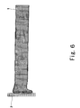
- Fig. 6 is an explanatory view schematically showing a fourth stage of the deformation mode of the front end portion of the energy absorbing member according to the present invention;
- Fig. 7 is an explanatory view schematically showing a fifth stage of the deformation mode of the front end portion of the energy absorbing member according to the present invention;
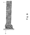
- Fig. 8 is an explanatory view schematically showing a sixth stage of the deformation mode of the front end portion of the energy absorbing member according to the present invention;
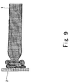
- Fig. 9 is an explanatory view schematically showing a seventh stage of the deformation mode of the front end portion of the energy absorbing member according to the present invention;
- Fig. 10 is an explanatory view schematically showing an eighth stage of the deformation mode of the front end portion of the energy absorbing member according to the present invention;
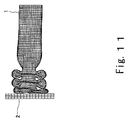
- Fig. 11 is an explanatory view schematically showing a ninth stage of the deformation mode of the front end portion of the energy absorbing member according to the present invention;
- Fig. 12(A) is a graph showing the relationship between a first peak force generated in an initial stage of collision and a size of a deformation starting portion;
- Fig. 12(B) is a graph showing the relationship between a second peak force generated in a middle stage of collision and a size of the deformation staring portion;
- Fig. 12(C) is a graph showing the relationship between a ratio between the first peak force and the second peak force and a size of the deformation starting portion;
- Fig. 13 is a side view showing an example in which a collision energy absorbing structure of a vehicle according to the present invention is applied to a coupler of a railroad vehicle;
- Fig. 14 is a plan view showing the collision energy absorbing structure of the vehicle of Fig. 13;
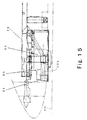
- Fig. 15 is a side view showing an example in which the collision energy absorbing structure of the vehicle according to the present invention is applied to a rail guard of a front vehicle of the railroad vehicle;
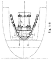
- Fig. 16 is a plan view showing a collision energy absorbing structure of the vehicle of Fig. 15;
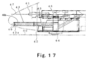
- Fig. 17 is a side view showing an example in which the collision energy absorbing structure of the vehicle according to the present invention is mounted to a front portion of a front vehicle of the railroad vehicle; and
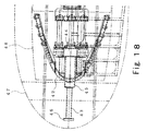
- Fig. 18 is a plan view showing the collision energy absorbing structure of the vehicle of Fig. 17.
-
- Hereinafter, a preferred embodiment of the present invention will be described with reference to drawings.
- Fig. 1 is a perspective view showing an energy absorbing member used in a collision energy absorbing structure of a vehicle according to the present invention.
- Referring now to Fig. 1, there is shown a tubular energy absorbing pipe member 1 (energy absorbing member) with rectangular cross section. The energy absorbing
pipe member 1 is provided with acutout portion 1a having an axial dimension L and a width dimension B on the left side of a frontend portion S 1 which corresponds to a deformation starting portion that has channel-shaped open cross section and is laterally asymmetrical. Here, the width dimension B of thecutout portion 1a is equal to substantially 1/2 of a width W of themember 1. - The energy absorbing
pipe member 1 has a closed cross-section structure having fourflat plate portions cutout portion 1a is formed by theflat plate portion 1A and parts of theflat plate portions flat plate portion 1A at the front end portion (deformation starting portion) S1. The front end portion S1 provided with thecutout portion 1a functions as a trigger portion for triggering bellows-like deformation for energy absorption and has the channel-shaped open cross section. While corner portions of thecutout portion 1a have certain degrees, for example, 90 degrees in Fig. 1, they may be curved. - In other words, the channel-shaped deformation starting portion (extended portion)
S 1 is extended from the whole width of theflat plate portion 1A, and part of theflat plate portion 1B and part of theflat plate portion 1C. Theextended portion S 1 has a length L as shown in Fig. 1. - When the axial force is evenly applied to the front end face of the tubular energy absorbing
pipe member 1 with rectangular cross section, deformation (bellows-like deformation) that is laterally asymmetric starts from the deformation startingportion S 1 corresponding to the extended portion having low strength. In brief, the deformation starting portion S1 is deformed in the initial stage of collision, which deformation triggers the bellows-like deformation mentioned later. - In the bellows-like deformation (buckling deformation) of the deformation starting portion S1 (trigger portion) in the initial stage of collision, since the deformation starting portion S1 is laterally asymmetrical and has the open cross section because of the
cutout portion 1a and initial force necessary for generating the bellows-like deformation as the result of collision is therefore small, the peak of the initial force in the collision is considerably reduced as compared to the case where thetubular pipe member 1 with rectangular cross section is deformed like bellows without thecutout portion 1a. - Then, the bellows-like deformation (buckling deformation) of the deformation starting portion S1 (right-half portion) of the energy absorbing
pipe member 1 gradually progresses and reaches a general portion S2 as the closed cross section. Since the asymmetric bellows-like deformation has been already generated, new bellows-like deformation does not occur in the entire general portion S2, but occurs in the left half portion of the general portion S2. So, there is a difference between the time when the initial force (force peak) at the start of the buckling deformation of the deformation starting portion S1 is generated and the time when the initial force at the start of the buckling deformation of the general portion S2 is generated. For this reason, the force necessary for causing the bellows-like deformation in the energy absorbingpipe member 1 is divided into the force at the start of the bellows-like deformation of the deformation starting portion S1 and the force for the start of the bellows-like deformation of the general portion S2. As a result, the peak force in the initial stage of collision is reduced and a constant reaction force is kept. Therefore, the impact acting on the passengers is relieved without a rapid rise in the impact force. - Thus, the bellows-like deformation of the deformation starting portion S1 triggers the bellows-like deformation of the general portion S2. Once the bellows-like deformation occurs in the general portion S2, stable bellows-like deformation continues thereafter. In this case, since the axial (longitudinal) force applied to the energy absorbing
pipe member 1 is considerably higher than the force orthogonal to the axial force, transitions of the bellows-like deformation from the deformation startingportion S 1 to the general portion S2 smoothly takes place. - Fig. 2 shows a result of computer simulation analysis of the relationship between the force and displacement of this deformation. Figs. 3 through 11 are views schematically showing change occurring when the collision force is applied to a
contact plate 2 provided at the front end of the energy absorbingpipe member 1. In the state of Fig. 3 before collision, no force is applied and the forces in the states of Figs. 4 through 11 correspond to the forces at force peak points P1 - P8 in Fig. 2. As shown in Figs. 3 through 11, thecontact plate 2 is provided on the deformation startingportion S 1 of the energy absorbingpipe member 1. In these cases, thecutout portion 1a is formed at the upper half portion of the front end portion (see Figs. 4 through 11). In other words, the deformation starting portion (extended portion)S 1 is extended from the lower half portion of the front end of the energy absorbingpipe member 1. - The state before collision is shown in Fig. 3. Once the collision occurs and the axial collision force (dynamic force) is applied through the
contact plate 2, first, the deformation startingportion S 1 corresponding to the lower half portion of the energy absorbingpipe member 1 starts to be deformed by buckling. Then, as shown in Fig. 5, the upper flat plate portion of the upper half portion of the closed cross-section structure of the energy absorbingpipe member 1 starts to be deformed by buckling, and then, as shown in Fig. 6, right and left flat plate portions of the closed cross-section structure starts to be deformed by buckling. In this case, a force peak point P1 corresponding to Fig. 4 at which the deformation startingportion S 1 starts bellows-like deformation is substantially equal to a force peak point P2 corresponding to Fig. 5 at which the general portion S2 starts bellows-like deformation, although the force peak point P2 is slightly greater than the force peak point P1, thus keeping a constant reaction force. - Once the bellows-like deformation starts, the buckling deformation of the upper and lower flat plate portions (see Figs. 7, 9, and 11) and the buckling deformation of the right and left flat plate portions (see Figs. 8, 10) are alternately repeated. Also, in these cases, the constant reaction force can be maintained without significant force fluctuation.
- The reason why the reaction force in the initial stage of the collision decreases as shown in Fig. 2, is that there is a difference between the time when the buckling deformation of the upper flat plate portion starts and the time when the buckling deformation of the lower flat plate portion starts in the states of Figs. 4, 5, and in the state of Fig. 6 and thereafter, the deformation in its previous stage facilitates the buckling deformation.
- Also, the deformation in the initial stage is asymmetric (see Figs. 4 through 6) and then becomes symmetric. This is because the buckling deformation of the right and left flat plate portions starts from deformation oblique with respect to the axial direction in the state of Fig. 7, and with a progress, this deformation gradually changes into deformation in the direction orthogonal to the axial direction.
- Subsequently, simulation analysis results of how the size of the
cutout portion 1a affects the initial force will be explained with reference to Figs. 12(A), (B), (C). In Figs. 12(A), 12(B), 12(C), B denotes a width of thecutout portion 1a, L denotes an axial length of thecutout portion 1a, and Ac, As respectively denote the cross-sectional area of the deformation starting portion S1 and the cross-sectional area of the general portion S2. - As can be seen from Fig. 12(A), the first peak force generated just after the collision tends to decrease with an increase in the size of the
cutout portion 1a i.e., with an increase in Ac/As, whereas, as can be seen from Fig. 12(B), the following second peak force tends to increase with the increase in thecutout portion 1a. - Since it is desirable that there is no great difference between the first and second peak forces and the force fluctuates evenly, judging from Fig. 12(C), the ratio Ac/As between the cross-sectional area of the deformation starting
portion S 1 and the cross-sectional area of the general portion S2 is preferably approximately 0.5. It is confirmed that the similar tendency and results are obtained in the tubular member with square cross section and the tubular member with rectangular cross section. - In this example, the energy absorbing member is applied to a coupler of a railroad vehicle.
- Referring to Figs. 13, 14, a
rubber damper 11 comprises adraft stop 12 having afront support portion 12a and arear support portion 12b, front and rearimpact absorbing rubbers front support portion 12a and therear support portion 12b of thedraft stop 12, a pair of connectingrod members impact absorbing rubbers draft stop 12, andflange members rod member 14R and a rear portion of the connectingrod member 14L and interposing theimpact absorbing rubbers draft stop 12. The front end portions of the connectingrod members front support frame 16 F, which is connected to a rear end portion of acoupler 18 with anintermediate member 17 interposed therebetween. - Front end portions of a pair of energy absorbing
pipe members rear flange member 15b and rear end portions of the energy absorbingpipe members rear support frame 21 supported by avehicle body frame 20. The energy absorbingpipe members cutout portions pipe members pipe members - With this constitution, by supporting the
rubber damper 11 by means of the energy absorbingpipe members rubber damper 11 is absorbed by the bellows-like deformation (plastic deformation) of the energy absorbingpipe members pipe members rubber damper 11 when insufficient, and the event that the vehicle is severely damaged or significant impact acts on passengers can be avoided. - In this example, the energy absorbing member is applied to a rail guard of a front vehicle of a railroad vehicle.
- Referring to Figs. 15, 16, a rail guard board 31 for eliminating obstacles is bent like horseshoe and mounted and fixed to a
vehicle body frame 32. Two energy absorbingpipe members 33 are placed behind the rail guard board 31 so as to be spaced apart therefrom. These energy absorbingpipe members 33 are coupled by means of a coupling member 33b and supported by asupport device 34. More specifically, the flat-plate shaped coupling member 33b is connected to tip ends of the respective energy absorbingpipe members 33 and rear ends of themembers 33 are fixed to thesupport device 34. An upper end portion of thesupport device 34 is fixed to thevehicle body frame 32. In this case, the cutout portions 33a of the respective energy absorbingpipe members 33 are opened outwardly (or inwardly) and laterally symmetric as shown in Fig. 16. In other words, the energy absorbingpipe members 33 are laterally symmetric to allowdeformation staring portions 33c provided at front ends of the energy absorbingpipe members 33 to be inwardly located.Reference numeral 50 denotes a rail. - With this constitution, the energy, which remains partially unabsorbed as the result of the deformation of the rail guard board 31, is absorbed by the energy absorbing
pipe members 33, thereby relieving the impact on thevehicle body frame 32. - In addition, lightweight is achieved. Specifically, although the energy remaining partially unabsorbed as the result of the deformation of the rail guard board has been conventionally absorbed by the energy absorbing plate composed of flat springs and provided behind the front side of the rail guard board, and the weight is correspondingly increased, the use of the energy absorbing
pipe members 33 provides significant lightweight. - In this example, the impact absorbing member is mounted to the front portion of the front vehicle of the railroad vehicle to absorb the collision energy when front vehicles head-on collide.
- Referring to Figs. 17, 18, an energy absorbing pipe member 43 is provided between a coupler 41 located on an upper side and a rail guard plate 42 located on a lower side in the vertical direction. A support pipe member 45 is provided so as to extend in the longitudinal direction of the vehicle from a support device 44 and a rear end portion of the energy absorbing pipe member 43 provided with a tip member 46 is connected to a tip end portion of the support pipe member 45.
- The support pipe member 45 extends forwardly of the rail guard board 42 and has a length so as to be located behind the coupler 41. When the vehicle is not used as the front vehicle, the energy absorbing pipe member 43 is removed from the vehicle to allow vehicles to be interconnected by means of the coupler 41. Reference numeral 48 denotes a vehicle body frame. At a portion where the energy absorbing pipe member 43 is connected to the tip member 46, the cutout portion 43a is provided at a lower portion thereof and laterally symmetric. In other words, the energy absorbing pipe member 43 is placed so that a
deformation starting portion 43b extended from the tip end of the energy absorbing pipe member 43 is located on the upper side. The tip member 46 is located in acover 47 on the tip side. Similarly to the examples, 1, 2, it is needless to say that two energy absorbing pipe members symmetrically placed may support a collision member. - With this constitution, when the front vehicles collide with each other, the tip member 46 collides with the tip member 46 of the opposed vehicle, thereby causing the energy absorbing pipe member 43 to be deformed by buckling to absorb the collision energy. Consequently, damage to the other parts can be avoided. Similarly, the opposed vehicle is provided with the energy absorbing pipe member and the tip member.
- The present invention is carried out as described above and has the following advantages.
- In the collision energy absorbing structure according to the present invention, to deal with the collision in which the force in the longitudinal direction of the vehicle is applied, the cutout portion with the open cross section is formed at the front end portion of the energy absorbing member, and from the front end portion, the deformation starts. In other words, the substantially channel-shaped deformation starting portion is extended from part of the front end of the energy absorbing member. This constitution facilitates the deformation of the front end portion and reduces the initial force peak for generating the bellows-like deformation, and also makes the deformation of the front end portion trigger the following bellows-like deformation and reduces the corresponding force peak. Thereby, the bellows-like deformation occurs naturally and the collision energy can be efficiently absorbed. In other words, since the force peak in the initial stage of collision and the following force peak can be made small and substantially equal and the constant reaction force can be maintained, the impact acting on the passengers can be relieved without a rapid rise in the impact force. In particular, since the cutout portion is provided at the tubular energy absorbing pipe member with rectangular cross section as the energy absorbing member, having equal cross-section dimension and plate thickness and including no inside ribs, the member can be manufactured easily and at a low cost.
- In addition, since the plurality of impact absorbing members are vertically or laterally symmetric, the impact force in the traveling direction can be evenly applied to the front end portion of the energy absorbing member so as to cause the bellows-like deformation without falling the energy absorbing member.
- Further, since the rubber damper is connected to the vehicle coupler, for relieving the impact generated between the vehicles, the front end portion of the energy absorbing member is connected to the rear end portion of the rubber damper, and the rear end portion of the energy absorbing member is connected to the draft stop mounted to the vehicle body frame, the small collision energy can be absorbed by the rubber damper and the great collision energy can be absorbed by bellows-like deformation of the energy absorbing member.
- Still further, by providing the energy absorbing member behind the rail guard board for eliminating obstacles on the rail during traveling and connecting the rear end portion of the energy absorbing member to the vehicle body frame by means of the support device, the excessive collision energy applied to the rail guard board can be absorbed by the bellows-like deformation of the energy absorbing member.
- Moreover, by connecting the rear end portion of the energy absorbing member extending forwardly of the coupler and provided with the collision member at the front end to the front end portion of the support device (support pipe member) mounted to the vehicle body frame, provided behind the coupler, and extending forwardly of the rail guard board, the collision energy can be absorbed by the bellows-like deformation of the energy absorbing member and the impact acting on the passengers can be relieved.
- As this invention may be embodied in several forms without departing from the spirit of essential characteristics thereof, the present embodiments are therefore illustrative and not restrictive, since the scope of the invention is defined by the appended claims rather than by the description preceding them, and all changes that fall within meters and bounds of the claims, or equivalence of such meters and bounds thereof are therefore intended to be embodied by the claims.
Claims (11)
- A collision energy absorbing structure of a vehicle comprising:a tubular energy absorbing member with rectangular cross section, provided in the longitudinal direction of the vehicle and having four flat plate portions, the tubular energy absorbing member being adapted to receive a collision force in the longitudinal direction of the vehicle and deformed like bellows by buckling, so as to absorb a collision energy; anda deformation starting portion provided by forming a cutout portion in one of right and left sides or one of upper and lower sides of a front end portion of the energy absorbing member.
- The collision energy absorbing structure according to Claim 1, wherein the cutout portion is formed in parts of three flat plate portions comprised of one of the four flat plate portions and flat plate portions located on both sides thereof.
- A collision energy absorbing structure of a vehicle comprising:a tubular energy absorbing member with rectangular cross section, provided in the longitudinal direction of the vehicle and having four flat plate portions, the tubular energy absorbing member being adapted to receive a collision force in the longitudinal direction of the vehicle and deformed like bellows by buckling, so as to absorb a collision energy; anda deformation starting portion extended from part of the front end portion so as to be substantially channel shaped.
- The collision energy absorbing structure according to Claim 1, further comprising:a rubber damper connected to a coupler of the vehicle, for relieving impact generated between vehicles, whereina front end portion of the energy absorbing member is connected to a rear end portion of the rubber damper and a rear end portion of the energy absorbing member is connected to a draft stop mounted to a vehicle body frame.
- The collision energy absorbing structure according to Claim 1, wherein the energy absorbing member is provided behind a rail guard board for eliminating obstacles on a rail during traveling and a rear end portion of the energy absorbing member is connected to a support device mounted to a vehicle body frame.
- The collision energy absorbing structure according to Claim 1, further comprising:a support device mounted to a vehicle body frame, provided behind a coupler, and extending forwardly of a rail guard board, wherein a rear end portion of the energy absorbing member is connected to a front end portion of the support device, and the energy absorbing member extends forwardly of the coupler.
- The collision energy absorbing structure according to Claim 1, wherein a plurality of energy absorbing members are provided so as to be vertically or laterally symmetric.
- The collision energy absorbing structure according to Claim 7, further comprising:a rubber damper connected to a coupler of the vehicle, for relieving impact generated between vehicles, wherein a front end portion of the energy absorbing member is connected to a rear end portion of the rubber damper and a rear end portion of the energy absorbing member is connected to a draft stop mounted to a vehicle body frame.
- The collision energy absorbing structure according to Claim 7, wherein the energy absorbing member is provided behind a rail guard board for eliminating obstacles on a rail during traveling and a rear end portion of the energy absorbing member is connected to a support device mounted to a vehicle body frame.
- The collision energy absorbing structure according to Claim 7, further comprising: a support device mounted to a vehicle body frame, provided behind a coupler, and extending forwardly of a rail guard board, wherein a rear end portion of the energy absorbing member is connected to a front end portion of the support device, and the energy absorbing member extends forwardly of the coupler.
- A collision energy absorbing structure comprising an elongate member (1; 19L,19R;33;43) for absorbing collision energy by buckling deformation, said member having a cylindrical portion (S2) with a symmetrical rectangular uniform cross-section and a leading portion (S1;19a,19b;33c;43b) of unsymmetrical cross-section for assisting an initial stage (P1,P2) of said buckling deformation.
Applications Claiming Priority (2)
| Application Number | Priority Date | Filing Date | Title |
|---|---|---|---|
| JP2001122028A JP3512753B2 (en) | 2001-04-20 | 2001-04-20 | Railcar collision energy absorption structure |
| JP2001122028 | 2001-04-20 |
Publications (3)
| Publication Number | Publication Date |
|---|---|
| EP1251054A2 true EP1251054A2 (en) | 2002-10-23 |
| EP1251054A3 EP1251054A3 (en) | 2003-05-07 |
| EP1251054B1 EP1251054B1 (en) | 2007-08-15 |
Family
ID=18971806
Family Applications (1)
| Application Number | Title | Priority Date | Filing Date |
|---|---|---|---|
| EP02252737A Expired - Lifetime EP1251054B1 (en) | 2001-04-20 | 2002-04-18 | Collision energy absorbing structure of vehicle |
Country Status (7)
| Country | Link |
|---|---|
| US (2) | US6889617B2 (en) |
| EP (1) | EP1251054B1 (en) |
| JP (1) | JP3512753B2 (en) |
| AT (1) | ATE370041T1 (en) |
| DE (1) | DE60221737T2 (en) |
| SG (1) | SG111939A1 (en) |
| TW (1) | TW537984B (en) |
Cited By (7)
| Publication number | Priority date | Publication date | Assignee | Title |
|---|---|---|---|---|
| EP1468889A1 (en) * | 2003-04-14 | 2004-10-20 | Kawasaki Jukogyo Kabushiki Kaisha | Coupler for a railway vehicle, with a rubber damper and energy absorbing members |
| EP1468890A1 (en) * | 2003-04-19 | 2004-10-20 | Kawasaki Jukogyo Kabushiki Kaisha | Rail guard support structure of a railway vehicle |
| EP1930227A1 (en) * | 2006-12-04 | 2008-06-11 | ANSALDOBREDA S.p.A. | Obstacle deflector for a front carriage of a train |
| FR2915451A1 (en) * | 2007-04-26 | 2008-10-31 | Vallourec Vitry | PROLONGED WITH PERFECTED SUPPORT. |
| EP2168838A1 (en) * | 2008-09-30 | 2010-03-31 | Hitachi Ltd. | Railway vehicle having a shock absorbing device |
| EP2236380A1 (en) * | 2009-03-31 | 2010-10-06 | Hitachi, Ltd. | Railway vehicle having shock absorbing device |
| EP2641803A4 (en) * | 2010-11-19 | 2017-06-21 | Kawasaki Jukogyo Kabushiki Kaisha | Collision energy absorbing body for railway rolling stock |
Families Citing this family (39)
| Publication number | Priority date | Publication date | Assignee | Title |
|---|---|---|---|---|
| FR2855805B1 (en) * | 2003-06-06 | 2005-08-05 | Vallourec Vitry | STRUCTURE ELEMENT FOR VEHICLE CAPABLE OF IMPROVED SHOCK BEHAVIOR |
| WO2005010397A1 (en) * | 2003-07-28 | 2005-02-03 | Sumitomo Metal Industries, Ltd. | Impact-absorbing member |
| CA2539383A1 (en) * | 2003-09-19 | 2005-03-31 | Siemens Transportation Systems, Inc. | Integrated impact protecting system |
| JP2005153567A (en) * | 2003-11-20 | 2005-06-16 | Toyota Motor Corp | Shock absorbing member |
| AT501690A1 (en) * | 2004-09-03 | 2006-10-15 | Siemens Transportation Systems | OPEN PROTECTION FOR RAIL VEHICLES |
| US8109535B2 (en) * | 2004-12-13 | 2012-02-07 | Ford Global Technologies | Sport utility vehicle (SUV) frame architecture for improved vehicle-to-vehicle compatibility |
| JP4943905B2 (en) * | 2006-05-10 | 2012-05-30 | 株式会社日立製作所 | Collision energy absorbing device and rail vehicle equipped with the same |
| JP4712604B2 (en) * | 2006-05-10 | 2011-06-29 | 株式会社日立製作所 | Transport equipment |
| JP4762054B2 (en) * | 2006-06-01 | 2011-08-31 | 川崎重工業株式会社 | Exhaust device for railway vehicles |
| JP4849971B2 (en) * | 2006-06-21 | 2012-01-11 | 川崎重工業株式会社 | Connecting shock absorber mounting structure |
| JP5092323B2 (en) * | 2006-09-08 | 2012-12-05 | 株式会社日立製作所 | Rail vehicle |
| JP5089277B2 (en) * | 2007-07-18 | 2012-12-05 | 株式会社日立製作所 | Rail vehicle equipped with an obstacle device |
| JP2009096225A (en) * | 2007-10-12 | 2009-05-07 | Kobe Steel Ltd | Energy absorbing member |
| JP4486673B2 (en) * | 2007-12-11 | 2010-06-23 | 本田技研工業株式会社 | Body structure |
| US20090174219A1 (en) * | 2008-01-04 | 2009-07-09 | Foreman Grant G | Vehicle energy absorber structure and method |
| BRPI0917647A2 (en) * | 2008-09-15 | 2015-11-17 | Voith Patent Gmbh | module to be fitted to the front end of a rail vehicle, in particular a rail vehicle. |
| US9187127B2 (en) | 2008-09-19 | 2015-11-17 | Ford Global Technologies, Llc | Twelve-cornered strengthening member, assemblies including a twelve-cornered strengthening member, and methods of manufacturing and joining the same |
| US8641129B2 (en) * | 2008-09-19 | 2014-02-04 | Ford Global Technologies, Llc | Twelve-cornered strengthening member |
| US9533710B2 (en) * | 2008-09-19 | 2017-01-03 | Ford Global Technologies, Llc | Twelve-cornered strengthening member |
| US8539737B2 (en) | 2008-09-19 | 2013-09-24 | Ford Global Technologies, Llc | Twelve-cornered strengthening member |
| JP5121677B2 (en) | 2008-11-25 | 2013-01-16 | 日本車輌製造株式会社 | Shock absorbing member |
| CN103052553B (en) * | 2010-09-20 | 2015-11-25 | 庞巴迪运输有限公司 | For the light weight compound cockpit structure of track vehicle |
| JP5584597B2 (en) * | 2010-11-19 | 2014-09-03 | 川崎重工業株式会社 | Railroad vehicle drainage device |
| US8459726B2 (en) | 2011-04-15 | 2013-06-11 | Ford Global Technologies, Llc. | Multi-cornered strengthening members |
| DE102011052770A1 (en) * | 2011-08-17 | 2013-02-21 | Kirchhoff Automotive Deutschland Gmbh | Vehicle bumper assembly has energy absorption components, which are formed and connected such that energy to be absorbed is introduced in one portion of cross-sectional area of energy absorption components |
| US10315698B2 (en) | 2015-06-24 | 2019-06-11 | Ford Global Technologies, Llc | Sixteen-cornered strengthening member for vehicles |
| US9944323B2 (en) | 2015-10-27 | 2018-04-17 | Ford Global Technologies, Llc | Twenty-four-cornered strengthening member for vehicles |
| US9889887B2 (en) | 2016-01-20 | 2018-02-13 | Ford Global Technologies, Llc | Twelve-cornered strengthening member for a vehicle with straight and curved sides and an optimized straight side length to curved side radius ratio |
| US9789906B1 (en) | 2016-03-23 | 2017-10-17 | Ford Global Technologies, Llc | Twenty-eight-cornered strengthening member for vehicles |
| US10704638B2 (en) | 2016-04-26 | 2020-07-07 | Ford Global Technologies, Llc | Cellular structures with twelve-cornered cells |
| US10393315B2 (en) | 2016-04-26 | 2019-08-27 | Ford Global Technologies, Llc | Cellular structures with twelve-cornered cells |
| US10473177B2 (en) | 2016-08-23 | 2019-11-12 | Ford Global Technologies, Llc | Cellular structures with sixteen-cornered cells |
| US10220881B2 (en) | 2016-08-26 | 2019-03-05 | Ford Global Technologies, Llc | Cellular structures with fourteen-cornered cells |
| US10300947B2 (en) | 2016-08-30 | 2019-05-28 | Ford Global Technologies, Llc | Twenty-eight-cornered strengthening member for vehicles |
| US10279842B2 (en) | 2016-08-30 | 2019-05-07 | Ford Global Technologies, Llc | Twenty-eight-cornered strengthening member for vehicles |
| US10429006B2 (en) | 2016-10-12 | 2019-10-01 | Ford Global Technologies, Llc | Cellular structures with twelve-cornered cells |
| US11072375B2 (en) | 2019-01-14 | 2021-07-27 | Fca Us Llc | Control arm with tunable fracture features |
| US20220314912A1 (en) * | 2019-09-06 | 2022-10-06 | Kirchhoff Automotive Deutschland Gmbh | Bumper Crossbeam For A Motor Vehicle |
| US11292522B2 (en) | 2019-12-04 | 2022-04-05 | Ford Global Technologies, Llc | Splayed front horns for vehicle frames |
Citations (2)
| Publication number | Priority date | Publication date | Assignee | Title |
|---|---|---|---|---|
| JPH09277953A (en) | 1996-04-12 | 1997-10-28 | Nippon Steel Corp | Shock absorbing member |
| JPH09277954A (en) | 1996-04-15 | 1997-10-28 | Nippon Steel Corp | Tapered impact absorbing member |
Family Cites Families (19)
| Publication number | Priority date | Publication date | Assignee | Title |
|---|---|---|---|---|
| US3888502A (en) * | 1972-05-08 | 1975-06-10 | Gen Motors Corp | Energy absorber components for use in vehicles particularly motor vehicles |
| US3838778A (en) * | 1972-10-06 | 1974-10-01 | Unilan Ag | Draft gear |
| US3828778A (en) * | 1973-01-22 | 1974-08-13 | Master Molded Prod Corp | Disposable ointment applicator |
| JPS58116467A (en) | 1981-12-28 | 1983-07-11 | Toray Ind Inc | Continuous preparation of amino-schiff base |
| US4706826A (en) * | 1985-04-22 | 1987-11-17 | Mcconway & Torley Corporation | Striker carrier having an adjustable wear plate for a railway coupler |
| US4715292A (en) * | 1985-09-13 | 1987-12-29 | Pavlick Michael J | Head end vehicle with crew accommodations with locomotive and other controls |
| US5080410A (en) * | 1991-04-22 | 1992-01-14 | Chrysler Corporation | Vehicle bumper beam |
| JP2650527B2 (en) | 1991-09-10 | 1997-09-03 | 日産自動車株式会社 | Car body strength member structure |
| JPH05139242A (en) * | 1991-11-19 | 1993-06-08 | Toyota Motor Corp | Body front part structure |
| JPH0663467A (en) | 1992-08-10 | 1994-03-08 | Asahi Sanac Kk | Photoelectric detector of object to be painted in automatic painting line |
| JP2882243B2 (en) | 1993-05-26 | 1999-04-12 | 三菱自動車工業株式会社 | Chassis components for vehicles |
| FR2712950B1 (en) | 1993-11-25 | 1995-12-29 | Gec Alsthom Transport Sa | Shock absorbing devices and method, frame and vehicle comprising such shock absorbing devices. |
| US5431445A (en) | 1994-11-28 | 1995-07-11 | Ford Motor Company | Asymmetrical beam structure for a vehicle |
| NL1000942C2 (en) | 1995-08-07 | 1997-02-11 | Reynolds Aluminium Bv | Absorption element with crumple zone for absorbing impact energy, and vehicle provided with such an absorption element. |
| JP3243783B2 (en) | 1995-09-01 | 2002-01-07 | 本田技研工業株式会社 | Vehicle side frame extension |
| DE19720329C1 (en) | 1997-05-15 | 1998-11-05 | Abb Daimler Benz Transp | Rail vehicle with shock absorbing element device |
| JPH115564A (en) | 1997-06-17 | 1999-01-12 | Mitsubishi Motors Corp | Side member structure of vehicle |
| US6062634A (en) * | 1997-11-17 | 2000-05-16 | Daimlerchrysler Corporation | Automotive energy absorbing structure |
| US6196135B1 (en) * | 1998-04-17 | 2001-03-06 | Kinki Sharyo Co., Ltd. | Shock absorbing underframe structure for railroad car |
-
2001
- 2001-04-20 JP JP2001122028A patent/JP3512753B2/en not_active Expired - Lifetime
-
2002
- 2002-04-02 TW TW091106577A patent/TW537984B/en not_active IP Right Cessation
- 2002-04-04 US US10/116,604 patent/US6889617B2/en not_active Expired - Fee Related
- 2002-04-09 SG SG200202120A patent/SG111939A1/en unknown
- 2002-04-18 DE DE60221737T patent/DE60221737T2/en not_active Expired - Lifetime
- 2002-04-18 AT AT02252737T patent/ATE370041T1/en not_active IP Right Cessation
- 2002-04-18 EP EP02252737A patent/EP1251054B1/en not_active Expired - Lifetime
-
2004
- 2004-06-18 US US10/871,452 patent/US6951176B2/en not_active Expired - Fee Related
Patent Citations (2)
| Publication number | Priority date | Publication date | Assignee | Title |
|---|---|---|---|---|
| JPH09277953A (en) | 1996-04-12 | 1997-10-28 | Nippon Steel Corp | Shock absorbing member |
| JPH09277954A (en) | 1996-04-15 | 1997-10-28 | Nippon Steel Corp | Tapered impact absorbing member |
Cited By (11)
| Publication number | Priority date | Publication date | Assignee | Title |
|---|---|---|---|---|
| EP1468889A1 (en) * | 2003-04-14 | 2004-10-20 | Kawasaki Jukogyo Kabushiki Kaisha | Coupler for a railway vehicle, with a rubber damper and energy absorbing members |
| EP1468890A1 (en) * | 2003-04-19 | 2004-10-20 | Kawasaki Jukogyo Kabushiki Kaisha | Rail guard support structure of a railway vehicle |
| EP1930227A1 (en) * | 2006-12-04 | 2008-06-11 | ANSALDOBREDA S.p.A. | Obstacle deflector for a front carriage of a train |
| FR2915451A1 (en) * | 2007-04-26 | 2008-10-31 | Vallourec Vitry | PROLONGED WITH PERFECTED SUPPORT. |
| WO2008145863A3 (en) * | 2007-04-26 | 2009-02-19 | Arcelormittal Tubular Products | Extension with improved support |
| CN101674958B (en) * | 2007-04-26 | 2012-08-01 | 安赛乐米塔尔-管材产品威蒂 | Extension with improved support |
| US8262151B2 (en) | 2007-04-26 | 2012-09-11 | Arcelormittal Tubular Products Vitry | Extension with improved support |
| RU2478495C2 (en) * | 2007-04-26 | 2013-04-10 | Арселормитталь Тьюбюлар Продактс Витри | Elongated element with perfected support |
| EP2168838A1 (en) * | 2008-09-30 | 2010-03-31 | Hitachi Ltd. | Railway vehicle having a shock absorbing device |
| EP2236380A1 (en) * | 2009-03-31 | 2010-10-06 | Hitachi, Ltd. | Railway vehicle having shock absorbing device |
| EP2641803A4 (en) * | 2010-11-19 | 2017-06-21 | Kawasaki Jukogyo Kabushiki Kaisha | Collision energy absorbing body for railway rolling stock |
Also Published As
| Publication number | Publication date |
|---|---|
| US6889617B2 (en) | 2005-05-10 |
| EP1251054B1 (en) | 2007-08-15 |
| ATE370041T1 (en) | 2007-09-15 |
| JP3512753B2 (en) | 2004-03-31 |
| US20040227378A1 (en) | 2004-11-18 |
| US20020153719A1 (en) | 2002-10-24 |
| DE60221737T2 (en) | 2008-06-05 |
| EP1251054A3 (en) | 2003-05-07 |
| DE60221737D1 (en) | 2007-09-27 |
| JP2002316642A (en) | 2002-10-29 |
| TW537984B (en) | 2003-06-21 |
| SG111939A1 (en) | 2005-06-29 |
| US6951176B2 (en) | 2005-10-04 |
Similar Documents
| Publication | Publication Date | Title |
|---|---|---|
| EP1251054B1 (en) | Collision energy absorbing structure of vehicle | |
| CN101428596B (en) | Impact absorbing member for vehicle | |
| US8287013B2 (en) | Impact absorbing member for vehicle | |
| EP0900717B1 (en) | Hollow frame member of aluminum alloy for vehicle body frame | |
| US20080093867A1 (en) | B-shaped beam with integrally-formed rib in face | |
| EP1426270B1 (en) | Vehicle body frame | |
| JP2008018792A (en) | Shock absorbing member for vehicle | |
| US6412836B1 (en) | Bumper system for motor vehicles | |
| KR20040097174A (en) | Bumper device | |
| JP2002012107A (en) | Bumper stay | |
| JP4232327B2 (en) | Bumpy stay | |
| KR100775806B1 (en) | Crash box in automotive bumper system | |
| JP4039032B2 (en) | Impact energy absorbing member | |
| JP2003312401A (en) | Bumper device | |
| JP4297810B2 (en) | Bumper stay and bumper structure | |
| JPH08216917A (en) | Structural member excellent in shock absorbing performance | |
| EP1468889A1 (en) | Coupler for a railway vehicle, with a rubber damper and energy absorbing members | |
| JP2003054445A (en) | Hollow structural member | |
| JP2005153567A (en) | Shock absorbing member | |
| CN114074626A (en) | Bumper component | |
| JP2005170232A (en) | Shock absorbing member | |
| JP2009096225A (en) | Energy absorbing member | |
| JP3333720B2 (en) | Aluminum alloy hollow frame member for body frame | |
| KR102492993B1 (en) | Side member for vehicle | |
| JP2003285703A (en) | Bumper reinforcing member with stay |
Legal Events
| Date | Code | Title | Description |
|---|---|---|---|
| PUAI | Public reference made under article 153(3) epc to a published international application that has entered the european phase |
Free format text: ORIGINAL CODE: 0009012 |
|
| AK | Designated contracting states |
Kind code of ref document: A2 Designated state(s): AT BE CH CY DE DK ES FI FR GB GR IE IT LI LU MC NL PT SE TR |
|
| AX | Request for extension of the european patent |
Free format text: AL;LT;LV;MK;RO;SI |
|
| PUAL | Search report despatched |
Free format text: ORIGINAL CODE: 0009013 |
|
| AK | Designated contracting states |
Designated state(s): AT BE CH CY DE DK ES FI FR GB GR IE IT LI LU MC NL PT SE TR |
|
| AX | Request for extension of the european patent |
Extension state: AL LT LV MK RO SI |
|
| 17P | Request for examination filed |
Effective date: 20030821 |
|
| AKX | Designation fees paid |
Designated state(s): AT BE CH CY DE DK ES FI FR GB GR IE IT LI LU MC NL PT SE TR |
|
| 17Q | First examination report despatched |
Effective date: 20050420 |
|
| GRAP | Despatch of communication of intention to grant a patent |
Free format text: ORIGINAL CODE: EPIDOSNIGR1 |
|
| GRAS | Grant fee paid |
Free format text: ORIGINAL CODE: EPIDOSNIGR3 |
|
| GRAA | (expected) grant |
Free format text: ORIGINAL CODE: 0009210 |
|
| AK | Designated contracting states |
Kind code of ref document: B1 Designated state(s): AT BE CH CY DE DK ES FI FR GB GR IE IT LI LU MC NL PT SE TR |
|
| REG | Reference to a national code |
Ref country code: GB Ref legal event code: FG4D |
|
| REG | Reference to a national code |
Ref country code: CH Ref legal event code: EP |
|
| REG | Reference to a national code |
Ref country code: IE Ref legal event code: FG4D |
|
| REF | Corresponds to: |
Ref document number: 60221737 Country of ref document: DE Date of ref document: 20070927 Kind code of ref document: P |
|
| PG25 | Lapsed in a contracting state [announced via postgrant information from national office to epo] |
Ref country code: FI Free format text: LAPSE BECAUSE OF FAILURE TO SUBMIT A TRANSLATION OF THE DESCRIPTION OR TO PAY THE FEE WITHIN THE PRESCRIBED TIME-LIMIT Effective date: 20070815 Ref country code: NL Free format text: LAPSE BECAUSE OF FAILURE TO SUBMIT A TRANSLATION OF THE DESCRIPTION OR TO PAY THE FEE WITHIN THE PRESCRIBED TIME-LIMIT Effective date: 20070815 Ref country code: ES Free format text: LAPSE BECAUSE OF FAILURE TO SUBMIT A TRANSLATION OF THE DESCRIPTION OR TO PAY THE FEE WITHIN THE PRESCRIBED TIME-LIMIT Effective date: 20071126 |
|
| NLV1 | Nl: lapsed or annulled due to failure to fulfill the requirements of art. 29p and 29m of the patents act | ||
| PG25 | Lapsed in a contracting state [announced via postgrant information from national office to epo] |
Ref country code: CH Free format text: LAPSE BECAUSE OF FAILURE TO SUBMIT A TRANSLATION OF THE DESCRIPTION OR TO PAY THE FEE WITHIN THE PRESCRIBED TIME-LIMIT Effective date: 20070815 Ref country code: AT Free format text: LAPSE BECAUSE OF FAILURE TO SUBMIT A TRANSLATION OF THE DESCRIPTION OR TO PAY THE FEE WITHIN THE PRESCRIBED TIME-LIMIT Effective date: 20070815 Ref country code: LI Free format text: LAPSE BECAUSE OF FAILURE TO SUBMIT A TRANSLATION OF THE DESCRIPTION OR TO PAY THE FEE WITHIN THE PRESCRIBED TIME-LIMIT Effective date: 20070815 |
|
| REG | Reference to a national code |
Ref country code: CH Ref legal event code: PL |
|
| PG25 | Lapsed in a contracting state [announced via postgrant information from national office to epo] |
Ref country code: BE Free format text: LAPSE BECAUSE OF FAILURE TO SUBMIT A TRANSLATION OF THE DESCRIPTION OR TO PAY THE FEE WITHIN THE PRESCRIBED TIME-LIMIT Effective date: 20070815 |
|
| PG25 | Lapsed in a contracting state [announced via postgrant information from national office to epo] |
Ref country code: GR Free format text: LAPSE BECAUSE OF FAILURE TO SUBMIT A TRANSLATION OF THE DESCRIPTION OR TO PAY THE FEE WITHIN THE PRESCRIBED TIME-LIMIT Effective date: 20071116 Ref country code: DK Free format text: LAPSE BECAUSE OF FAILURE TO SUBMIT A TRANSLATION OF THE DESCRIPTION OR TO PAY THE FEE WITHIN THE PRESCRIBED TIME-LIMIT Effective date: 20070815 |
|
| PG25 | Lapsed in a contracting state [announced via postgrant information from national office to epo] |
Ref country code: PT Free format text: LAPSE BECAUSE OF FAILURE TO SUBMIT A TRANSLATION OF THE DESCRIPTION OR TO PAY THE FEE WITHIN THE PRESCRIBED TIME-LIMIT Effective date: 20080115 |
|
| PLBE | No opposition filed within time limit |
Free format text: ORIGINAL CODE: 0009261 |
|
| STAA | Information on the status of an ep patent application or granted ep patent |
Free format text: STATUS: NO OPPOSITION FILED WITHIN TIME LIMIT |
|
| PG25 | Lapsed in a contracting state [announced via postgrant information from national office to epo] |
Ref country code: SE Free format text: LAPSE BECAUSE OF FAILURE TO SUBMIT A TRANSLATION OF THE DESCRIPTION OR TO PAY THE FEE WITHIN THE PRESCRIBED TIME-LIMIT Effective date: 20071115 |
|
| 26N | No opposition filed |
Effective date: 20080516 |
|
| PG25 | Lapsed in a contracting state [announced via postgrant information from national office to epo] |
Ref country code: MC Free format text: LAPSE BECAUSE OF NON-PAYMENT OF DUE FEES Effective date: 20080430 |
|
| GBPC | Gb: european patent ceased through non-payment of renewal fee |
Effective date: 20080418 |
|
| PG25 | Lapsed in a contracting state [announced via postgrant information from national office to epo] |
Ref country code: IE Free format text: LAPSE BECAUSE OF NON-PAYMENT OF DUE FEES Effective date: 20080418 |
|
| PG25 | Lapsed in a contracting state [announced via postgrant information from national office to epo] |
Ref country code: GB Free format text: LAPSE BECAUSE OF NON-PAYMENT OF DUE FEES Effective date: 20080418 |
|
| PG25 | Lapsed in a contracting state [announced via postgrant information from national office to epo] |
Ref country code: CY Free format text: LAPSE BECAUSE OF FAILURE TO SUBMIT A TRANSLATION OF THE DESCRIPTION OR TO PAY THE FEE WITHIN THE PRESCRIBED TIME-LIMIT Effective date: 20070815 |
|
| PG25 | Lapsed in a contracting state [announced via postgrant information from national office to epo] |
Ref country code: LU Free format text: LAPSE BECAUSE OF NON-PAYMENT OF DUE FEES Effective date: 20080418 |
|
| PG25 | Lapsed in a contracting state [announced via postgrant information from national office to epo] |
Ref country code: TR Free format text: LAPSE BECAUSE OF FAILURE TO SUBMIT A TRANSLATION OF THE DESCRIPTION OR TO PAY THE FEE WITHIN THE PRESCRIBED TIME-LIMIT Effective date: 20070815 |
|
| PG25 | Lapsed in a contracting state [announced via postgrant information from national office to epo] |
Ref country code: IT Free format text: LAPSE BECAUSE OF NON-PAYMENT OF DUE FEES Effective date: 20080430 |
|
| REG | Reference to a national code |
Ref country code: FR Ref legal event code: PLFP Year of fee payment: 15 |
|
| PGFP | Annual fee paid to national office [announced via postgrant information from national office to epo] |
Ref country code: FR Payment date: 20160309 Year of fee payment: 15 |
|
| PGFP | Annual fee paid to national office [announced via postgrant information from national office to epo] |
Ref country code: DE Payment date: 20160412 Year of fee payment: 15 |
|
| REG | Reference to a national code |
Ref country code: DE Ref legal event code: R119 Ref document number: 60221737 Country of ref document: DE |
|
| REG | Reference to a national code |
Ref country code: FR Ref legal event code: ST Effective date: 20171229 |
|
| PG25 | Lapsed in a contracting state [announced via postgrant information from national office to epo] |
Ref country code: DE Free format text: LAPSE BECAUSE OF NON-PAYMENT OF DUE FEES Effective date: 20171103 Ref country code: FR Free format text: LAPSE BECAUSE OF NON-PAYMENT OF DUE FEES Effective date: 20170502 |