EP1251047A2 - Retractor - Google Patents
Retractor Download PDFInfo
- Publication number
- EP1251047A2 EP1251047A2 EP02015484A EP02015484A EP1251047A2 EP 1251047 A2 EP1251047 A2 EP 1251047A2 EP 02015484 A EP02015484 A EP 02015484A EP 02015484 A EP02015484 A EP 02015484A EP 1251047 A2 EP1251047 A2 EP 1251047A2
- Authority
- EP
- European Patent Office
- Prior art keywords
- retractor
- locking mechanism
- lever
- lockout lever
- seat
- Prior art date
- Legal status (The legal status is an assumption and is not a legal conclusion. Google has not performed a legal analysis and makes no representation as to the accuracy of the status listed.)
- Granted
Links
Images


Classifications
-
- B—PERFORMING OPERATIONS; TRANSPORTING
- B60—VEHICLES IN GENERAL
- B60R—VEHICLES, VEHICLE FITTINGS, OR VEHICLE PARTS, NOT OTHERWISE PROVIDED FOR
- B60R22/00—Safety belts or body harnesses in vehicles
- B60R22/34—Belt retractors, e.g. reels
- B60R22/36—Belt retractors, e.g. reels self-locking in an emergency
- B60R22/40—Belt retractors, e.g. reels self-locking in an emergency responsive only to vehicle movement
-
- B—PERFORMING OPERATIONS; TRANSPORTING
- B60—VEHICLES IN GENERAL
- B60R—VEHICLES, VEHICLE FITTINGS, OR VEHICLE PARTS, NOT OTHERWISE PROVIDED FOR
- B60R22/00—Safety belts or body harnesses in vehicles
- B60R22/34—Belt retractors, e.g. reels
- B60R22/36—Belt retractors, e.g. reels self-locking in an emergency
-
- B—PERFORMING OPERATIONS; TRANSPORTING
- B60—VEHICLES IN GENERAL
- B60R—VEHICLES, VEHICLE FITTINGS, OR VEHICLE PARTS, NOT OTHERWISE PROVIDED FOR
- B60R22/00—Safety belts or body harnesses in vehicles
- B60R22/34—Belt retractors, e.g. reels
- B60R2022/3421—Belt retractors, e.g. reels with means for locking the belt reel in a non-use position, e.g. for seat mounted retractor when the seat is in a non-locked condition
Definitions
- This application is a divisional application deriving from 00 900 688.3.
- the present invention relates to a retractor for a vehicle safety restraint and particularly to a retractor for use in a rear seat.
- Retractors for rear seat belts are often mounted on the seat back rest itself since space is at a premium in the rear passenger compartment.
- the back rest For the seat belt to be effective the back rest must be fastened securely to a fixed part of the vehicle which would be the case in normal use.
- the rear seat back rest can be unlatched from its fastened upright position and rotated into a horizontal position to increase the luggage capacity of the vehicle.
- the back rest is split and one part may remain upright to accommodate a seated passenger while the other part is lowered to allow bulky luggage to overflow from the luggage compartment behind the seat back.
- the rear seat retractor is constructed in a similar manner to a front seat retractor and has both a web sensor and a vehicle sensor.
- the web sensor locks the retractor against pay-out if the belt webbing is suddenly jerked, as would happen if it were suddenly loaded by the inertia of the user in a crash. This is known technology.
- the vehicle sensor detects a sudden change of speed of the vehicle and locks the retractor, again in a manner known to those skilled in the art.
- the vehicle sensor typically comprises an inertia sensitive ball resting freely in a cup. A sudden deceleration of the vehicle causes the ball to keep moving and to ride up the side of the cup. A pawl resting on the ball is thus deflected upwards and this pawl activates a locking mechanism to lock the retractor spool against rotation and thus against further pay-out of webbing.
- the geometry of the ball type vehicle sensor means that it will also be activated if the retractor is tilted. This is used in the known systems described in DE 29 27 159 and GB 2 249 339 as an inherent seat back tilt sensor. If the seat back is not upright then the vehicle sensor locks the retractor against pay-out and it cannot be used.
- a sensor is located in the seat back latch itself. When this detects that the latch is securely fastened it releases an additional locking device on the retractor to allow the retractor to be used. This is an expensive system requiring an additional locking device to be fitted to the retractor.
- the present invention aims to provide an improved safety locking arrangement for a retractor in a rear seat.
- a retractor for a vehicle safety restraint for use in a rear vehicle seat comprising: a rotatable spool (2), for storing seat belt webbing, a retractor locking mechanism, for locking the spool (2) against rotation, means (16) connecting a seat latch to the locking mechanism, an override lockout lever (14),a resilient biasing means (15), arranged to bias the lockout lever (14) into an engaging position in which the retractor locking mechanism is engaged, wherein the connecting means (16) is arranged, under the influence of the seat latch, to move the lever (14) between the engaging position in which the locking mechanism engages, and an unengaged position in which the lever (14) is held clear of the locking mechanism and the locking mechanism is disengaged, and the retractor comprising a housing structure (34) wherein the override lockout lever (14), the resilient biasing means (15), and at least part of the connecting means (16) are located in said housing structure (34) to form a module which can be assembled into
- the locking mechanism comprises a vehicle sensor having an inertia sensitive ball resting freely in a cup.
- the override lockout lever may be arranged to act on the vehicle sensor so that in its engaging position it is biased to move the ball to a position in which the vehicle sensor is activated and the retractor is locked against payout of the seat belt webbing. In the unengaged position, the lever is held clear of the ball so that the retractor is unlocked and the webbing is free to pay out.
- the locking mechanism is moved in phase with the locking member, so as to maintain its control of the angular position of the locking member.
- the connecting means comprises a cable, for example a Bowden cable which has one end connected to the seat latch, and the other end connected to a spring biased slider acting on the retractor.
- a cable for example a Bowden cable which has one end connected to the seat latch, and the other end connected to a spring biased slider acting on the retractor.
- the Bowden cable is pulled away from the retractor locking mechanism and thus pulls the slider away from the locking mechanism.
- the Bowden cable remains in the extended state and the slider, under the spring influence, engages and activates the locking mechanism, thus locking the retractor against webbing payout.
- the retractor locking mechanism e.g. the vehicle sensor and retractor locking pawl
- the retractor locking mechanism is mounted in a so-called lockcup otherwise known as a multi-function piece which is attached to the side of the spool.
- the housing structure preferably surrounds an aperture in the bush through which the lever can pivot to engage the retractor locking means to lock the spool.
- the override lockout components can thus all be assembled from one side of the assembly. They can thus be installed at any stage of the assembly process and can be tested and checked as a module before the mechanism bush is assembled to the retractor, i.e. attached to the frame.
- a method of assembling a retractor for a vehicle safety restraint for use in a rear vehicle seat comprising first assembling, all from one side of the retractor, into a housing structure (34), an override lockout lever (14) movable into an engaging position locking the retractor and means connecting the seat latch to the retractor locking mechanism, and subsequently assembling the housing structure (34) to a retractor mechanism bush (32) and subsequently assembling the mechanism bush (32) to a retractor spool (2).
- a retractor according to the present invention has advantages over known override lockout systems because there are less parts, leading to cost savings and improved reliability. Also the main locking mechanism is maintained in the correct orientation with respect to the lockbar, inhibiting self engagement of the lockbar in normal use, and thus again improving reliability and also contributing to comfort and reducing noise.
- a vehicle safety retractor is shown generally at 1 and comprises a rotatable spool 2 with seat belt webbing 3 wound thereon.
- the spool 2 is rotatable about its longitudinal axis in bushings 4 in sides 5 of a retractor frame 6.
- On the left hand side (as illustrated) of the frame 6 is fixed a toothed ratchet wheel 7, and a web sensor disc.
- the web sensor disc is arranged to activate locking of the retractor when the webbing is pulled out suddenly as for example in a vehicle crash. This operates in known manner.
- the vehicle sensor 9 comprises an inertia sensitive ball 10 resting freely in a hollow cup 11.
- a pivoted hat 12 rests on the ball 10, and is coupled to a locking pawl 13 arranged for engagement, in the locking position, with the ratchet wheel 7 to lock the spool 2 against further webbing payout.
- the ball 10 is displaced and rolls up a side of the cup 11. This movement lifts the hat 12 and moves the pawl 13 into locking engagement with the ratchet wheel 7.
- An additional locking lever 14 is located adjacent the ball 10. It is biased by a spring 15 to the upward position in which it displaces the ball 10 into the retractor locking position.
- the locking lever 14 is connected to one end of a Bowden cable 16.
- the other end (not shown) of the Bowden cable 16 is connected to a rear seat latching mechanism (not shown). When the seat is securely latched the Bowden cable 16 is retracted away from the vehicle sensor and pulls the locking lever 14 away from the ball 10. Thus the spool is free to rotate and the retractor operates normally.
- FIGS 3 and 4 a different retractor is shown.
- a lockout lever 30 acts directly on a load bearing lockdog 31 which pivots to engage the spool 2 to lock the spool 2 against further payout of webbing.
- the cable 16 is protected by a sheath 32 in the region of the retractor.
- the cable 16 has an end 33 in auxiliary housing 35 which slides within housing 34.
- Auxiliary housing 35 is slidingly biased by the springs 15 and it abuts the retractor main locking pawl (or lockdog) 31.
- the lockdog 31 is pivoted about axis 40 and in its upward position contacts the spool 2 ( Figure 4) to lock it against further rotation and further webbing payout.
- the seat latch is securely fastened however the cable 16 works against the springs 15 pulling it and the sliding auxiliary housing 35 away to a downward (as illustrated) position.
- lockout lever 30 In this position the lockout lever 30 is in a lower position and hence lockdog 31 allows spool 2 to rotate and the webbing is free to pay out.
- the retractor locking mechanism is so designed that movement of the lockdog 31 causes the mechanism to move to its locked position. In this way inadvertent locking of the lockdog 31 is prevented
- the mechanism automatically locks the retractor and webbing cannot be pulled out from the spool. This alerts the passenger to the unlatched condition of the seat.
- the Bowden cable is retracted and the locking device operates to effectively disable the retractor. Thus the webbing cannot be pulled out to fasten the seat belt and this alerts the passenger that the seat is not secure.
- FIG 5 variation on the retractor of Figures 3 and 4 including a mechanism bush 32.
- This is a well known component of safety restraint retractors. It fits onto the side of the retractor to house the spool locking mechanism, i.e. the locking pawl 31 (not shown in Figure 5) and/or the vehicle sensor in housing recess 38 (facing away in the view of Figure 5).
- the mechanism bush 32 has a housing structure 34, for the override lockout components, including the pivoting lockout lever 30, biasing spring 15, Bowden cable 16 and sliding auxiliary housing 35.
- the sliding housing 35 contains the end 33 of cable 16 and the spring 15.
- a pair of pins 39 on the sides of the sliding housing 35 guide the sliding motion in slots in the housing structure 34.
- the housing structure 34 comprises an aperture the position of which is indicated at 36 through which the pivoting lockout lever 30 pivots to engage the retractor locking mechanism in the locking position by moving the ball.
- a cover 48 fits over the housing structure 34 to protect the components.
- the arrangement allows the override lockout components to be assembled into the mechanism bush 32 as a complete module for testing in advance of the bush being attached to the retractor. All of the lockout components are assembled into the bush from the same side. This streamlines the assembly line and reduces manufacturing costs. Also, the parts may be assembled to the mechanism bush after completion of the full retractor assembly allowing flexible assembly process if so desired.
Abstract
Description
- This application is a divisional application deriving from 00 900 688.3.
- The present invention relates to a retractor for a vehicle safety restraint and particularly to a retractor for use in a rear seat.
- Retractors for rear seat belts are often mounted on the seat back rest itself since space is at a premium in the rear passenger compartment. For the seat belt to be effective the back rest must be fastened securely to a fixed part of the vehicle which would be the case in normal use. However in some vehicles, such as so-called station-wagons or estate cars and so-called hatchback cars, the rear seat back rest can be unlatched from its fastened upright position and rotated into a horizontal position to increase the luggage capacity of the vehicle. In some models the back rest is split and one part may remain upright to accommodate a seated passenger while the other part is lowered to allow bulky luggage to overflow from the luggage compartment behind the seat back.
- In both cases there is a danger that when the seat back rest is returned to the upright position it may not be securely locked. In a crash, the rear passenger will then not be safely restrained because the retractor, attached to the seat back, will move when the seat back moves under the inertial loading caused by the crash.
- The rear seat retractor is constructed in a similar manner to a front seat retractor and has both a web sensor and a vehicle sensor. The web sensor locks the retractor against pay-out if the belt webbing is suddenly jerked, as would happen if it were suddenly loaded by the inertia of the user in a crash. This is known technology. The vehicle sensor detects a sudden change of speed of the vehicle and locks the retractor, again in a manner known to those skilled in the art.
- The vehicle sensor typically comprises an inertia sensitive ball resting freely in a cup. A sudden deceleration of the vehicle causes the ball to keep moving and to ride up the side of the cup. A pawl resting on the ball is thus deflected upwards and this pawl activates a locking mechanism to lock the retractor spool against rotation and thus against further pay-out of webbing.
- The geometry of the ball type vehicle sensor means that it will also be activated if the retractor is tilted. This is used in the known systems described in DE 29 27 159 and
GB 2 249 339 as an inherent seat back tilt sensor. If the seat back is not upright then the vehicle sensor locks the retractor against pay-out and it cannot be used. - However this known arrangement will not detect a rear seat back which is in the upright position but is not locked securely into the upright position. In this situation the retractor of the known arrangements could be used to fasten a vehicle occupant who will be unaware that the retractor is free to move and thus that he is not safely restrained.
- In the system described in
GB 2 286 624, a sensor is located in the seat back latch itself. When this detects that the latch is securely fastened it releases an additional locking device on the retractor to allow the retractor to be used. This is an expensive system requiring an additional locking device to be fitted to the retractor. - The present invention aims to provide an improved safety locking arrangement for a retractor in a rear seat.
- According to a first aspect of the present invention there is provided a retractor for a vehicle safety restraint for use in a rear vehicle seat, the retractor comprising: a rotatable spool (2), for storing seat belt webbing, a retractor locking mechanism, for locking the spool (2) against rotation, means (16) connecting a seat latch to the locking mechanism, an override lockout lever (14),a resilient biasing means (15), arranged to bias the lockout lever (14) into an engaging position in which the retractor locking mechanism is engaged, wherein the connecting means (16) is arranged, under the influence of the seat latch, to move the lever (14) between the engaging position in which the locking mechanism engages, and an unengaged position in which the lever (14) is held clear of the locking mechanism and the locking mechanism is disengaged, and the retractor comprising a housing structure (34) wherein the override lockout lever (14), the resilient biasing means (15), and at least part of the connecting means (16) are located in said housing structure (34) to form a module which can be assembled into a mechanism bush part (32) as a complete module.
- According to one embodiment of the invention the locking mechanism comprises a vehicle sensor having an inertia sensitive ball resting freely in a cup. The override lockout lever may be arranged to act on the vehicle sensor so that in its engaging position it is biased to move the ball to a position in which the vehicle sensor is activated and the retractor is locked against payout of the seat belt webbing. In the unengaged position, the lever is held clear of the ball so that the retractor is unlocked and the webbing is free to pay out.
- According to a preferred embodiment the locking mechanism is moved in phase with the locking member, so as to maintain its control of the angular position of the locking member.
- Preferably the connecting means comprises a cable, for example a Bowden cable which has one end connected to the seat latch, and the other end connected to a spring biased slider acting on the retractor. When the seat is securely latched the Bowden cable is pulled away from the retractor locking mechanism and thus pulls the slider away from the locking mechanism. When the seat is not securely latched then the Bowden cable remains in the extended state and the slider, under the spring influence, engages and activates the locking mechanism, thus locking the retractor against webbing payout.
- In a traditional retractor, the retractor locking mechanism, e.g. the vehicle sensor and retractor locking pawl, is mounted in a so-called lockcup otherwise known as a multi-function piece which is attached to the side of the spool.
- The housing structure preferably surrounds an aperture in the bush through which the lever can pivot to engage the retractor locking means to lock the spool. The override lockout components can thus all be assembled from one side of the assembly. They can thus be installed at any stage of the assembly process and can be tested and checked as a module before the mechanism bush is assembled to the retractor, i.e. attached to the frame.
- According to a second aspect of the invention there is provided a method of assembling a retractor for a vehicle safety restraint for use in a rear vehicle seat comprising first assembling, all from one side of the retractor, into a housing structure (34), an override lockout lever (14) movable into an engaging position locking the retractor and means connecting the seat latch to the retractor locking mechanism, and subsequently assembling the housing structure (34) to a retractor mechanism bush (32) and subsequently assembling the mechanism bush (32) to a retractor spool (2).
- A retractor according to the present invention has advantages over known override lockout systems because there are less parts, leading to cost savings and improved reliability. Also the main locking mechanism is maintained in the correct orientation with respect to the lockbar, inhibiting self engagement of the lockbar in normal use, and thus again improving reliability and also contributing to comfort and reducing noise.
- For a better understanding of the present invention, and to show how the same may be carried into effect, reference will now be made to the accompanying drawings, in which:
- Figure 1 shows a retractor in cross sectional view which may be used in the invention;
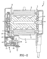
- Figure 2 shows an alternative retractor in cross sectional view which may be used in the invention;
- Figure 3 shows a further alternative retractor in cross sectional view which may be used in the invention;
- Figure 4 is a different cross sectional view to that shown in Figure 3.
- Figure 5 is an exploded perspective view of part of a retractor illustrating the invention.
-
- Throughout the Figures like reference numerals denote like parts.
- A vehicle safety retractor is shown generally at 1 and comprises a
rotatable spool 2 withseat belt webbing 3 wound thereon. Thespool 2 is rotatable about its longitudinal axis inbushings 4 insides 5 of aretractor frame 6. On the left hand side (as illustrated) of theframe 6 is fixed atoothed ratchet wheel 7, and a web sensor disc. The web sensor disc is arranged to activate locking of the retractor when the webbing is pulled out suddenly as for example in a vehicle crash. This operates in known manner. - Below this, as shown, is located a
vehicle sensor 9, the function of which is to activate locking of the retractor under conditions of sudden acceleration or deceleration of the vehicle, again indicative of a crash and again well known in the art. Thevehicle sensor 9 comprises an inertiasensitive ball 10 resting freely in ahollow cup 11. Apivoted hat 12 rests on theball 10, and is coupled to alocking pawl 13 arranged for engagement, in the locking position, with theratchet wheel 7 to lock thespool 2 against further webbing payout. When sudden acceleration of the vehicle occurs then theball 10 is displaced and rolls up a side of thecup 11. This movement lifts thehat 12 and moves thepawl 13 into locking engagement with theratchet wheel 7. - An
additional locking lever 14 is located adjacent theball 10. It is biased by aspring 15 to the upward position in which it displaces theball 10 into the retractor locking position. Thelocking lever 14 is connected to one end of a Bowdencable 16. The other end (not shown) of the Bowdencable 16 is connected to a rear seat latching mechanism (not shown). When the seat is securely latched the Bowdencable 16 is retracted away from the vehicle sensor and pulls thelocking lever 14 away from theball 10. Thus the spool is free to rotate and the retractor operates normally. - However, if the seat is not securely latched then the Bowden cable, under the influence of the
spring 15 acting through thelever 14, remains in an extended state, and thelever 14 contacts theball 10 and displaces it to the position in which the spool becomes locked against further webbing payout. - In Figure 1 the line of action of the
locking lever 14 is oriented obliquely to the vehicle sensor, and in Figure 2 it is oriented generally in a vertical plane. Otherwise Figures 1 and 2 show identical parts. - In Figures 3 and 4 a different retractor is shown. Here a
lockout lever 30 acts directly on aload bearing lockdog 31 which pivots to engage thespool 2 to lock thespool 2 against further payout of webbing. - In this retractor there are two biasing springs 15. The
cable 16 is protected by asheath 32 in the region of the retractor. Thecable 16 has anend 33 inauxiliary housing 35 which slides withinhousing 34.Auxiliary housing 35 is slidingly biased by thesprings 15 and it abuts the retractor main locking pawl (or lockdog) 31. Thelockdog 31 is pivoted aboutaxis 40 and in its upward position contacts the spool 2 (Figure 4) to lock it against further rotation and further webbing payout. When the seat latch is securely fastened however thecable 16 works against thesprings 15 pulling it and the slidingauxiliary housing 35 away to a downward (as illustrated) position. In this position thelockout lever 30 is in a lower position and hence lockdog 31 allowsspool 2 to rotate and the webbing is free to pay out. In this retractor, the retractor locking mechanism is so designed that movement of thelockdog 31 causes the mechanism to move to its locked position. In this way inadvertent locking of thelockdog 31 is prevented - When the seat is not secured the mechanism automatically locks the retractor and webbing cannot be pulled out from the spool. This alerts the passenger to the unlatched condition of the seat. Once the seat is again securely latched then the Bowden cable is retracted and the locking device operates to effectively disable the retractor. Thus the webbing cannot be pulled out to fasten the seat belt and this alerts the passenger that the seat is not secure.
- In Figure 5 variation on the retractor of Figures 3 and 4 including a
mechanism bush 32. This is a well known component of safety restraint retractors. It fits onto the side of the retractor to house the spool locking mechanism, i.e. the locking pawl 31 (not shown in Figure 5) and/or the vehicle sensor in housing recess 38 (facing away in the view of Figure 5). Themechanism bush 32 has ahousing structure 34, for the override lockout components, including thepivoting lockout lever 30, biasingspring 15,Bowden cable 16 and slidingauxiliary housing 35. The slidinghousing 35 contains theend 33 ofcable 16 and thespring 15. A pair ofpins 39 on the sides of the slidinghousing 35 guide the sliding motion in slots in thehousing structure 34. One of thepins 39 engages in the slot of the pivotinglockout lever 30 which pivots aboutaxis 40. Thehousing structure 34 comprises an aperture the position of which is indicated at 36 through which thepivoting lockout lever 30 pivots to engage the retractor locking mechanism in the locking position by moving the ball. A cover 48 fits over thehousing structure 34 to protect the components. - As can be seen, the arrangement allows the override lockout components to be assembled into the
mechanism bush 32 as a complete module for testing in advance of the bush being attached to the retractor. All of the lockout components are assembled into the bush from the same side. This streamlines the assembly line and reduces manufacturing costs. Also, the parts may be assembled to the mechanism bush after completion of the full retractor assembly allowing flexible assembly process if so desired.
Claims (8)
- A retractor for a vehicle safety restraint for use in a rear vehicle seat, the retractor comprising:wherein the connecting means (16) is arranged, under the influence of the seat latch, to move the lever (14) between the engaging position in which the locking mechanism engages, and an unengaged position in which the lever (14) is held clear of the locking mechanism and the locking mechanism is disengaged, and the retractor comprising a housing structure (34) wherein the override lockout lever (14), the resilient biasing means (15), and at least part of the connecting means (16) are located in said housing structure (34) to form a module which can be assembled into a mechanism bush part (32) as a complete module.a rotatable spool (2), for storing seat belt webbing,a retractor locking mechanism, for locking the spool (2) against rotation,means (16) connecting a seat latch to the locking mechanism, an override lockout lever (14),a resilient biasing means (15), arranged to bias the lockout lever (14) into an engaging position in which the retractor locking mechanism is engaged,
- A retractor according to claim 1 wherein the lockout lever (14), the resilient biasing means (15) and said part of the connecting means (16) are arranged so that they can be assembled all from the same side into the mechanism bush part (32) which fits onto a side of the retractor.
- A retractor according to any one of the preceding claims wherein the locking mechanism comprises a vehicle sensor (9) having an inertia sensitive ball (10) resting freely in a cup(11) and the override lockout lever (14) is biased to move the ball (10 ) to a position in which the vehicle sensor (9) is activated to lock the retractor against pay out of the seat belt webbing.
- A retractor according to claim 3 wherein the override lockout lever (14) is arranged so that in its unengaged position it is held clear of the ball (10) so that the retractor is unlocked and the webbing is free to pay out.
- A retractor according to any one of the preceding claims wherein the locking mechanism is moved in phase with the lockout lever (14), so as to maintain its control of the angular position of the lockout lever (14).
- A retractor according to any one of the preceding claims wherein the connecting means (16) comprises a cable which has one end connected to the seat latch and the other end connected to a spring biased slider acting on the lockout lever (14).
- A retractor according to any one of the preceding claims further wherein the mechanism bush part (23) has an aperture (36) formed therethrough and the housing structure (34) surrounds the aperture (36) and wherein the lockout lever (14) and the resilient biasing means (15) are mounted in the housing structure (34) so that the lever (14) can pivot through the aperture (36).
- A method of assembling a retractor for a vehicle safety restraint for use in a rear vehicle seat comprising first assembling, all from one side of the retractor, into a housing structure (34), an override lockout lever (14) movable into an engaging position locking the retractor and means connecting the seat latch to the retractor locking mechanism, and subsequently assembling the housing structure (34) to a retractor mechanism bush (32) and subsequently assembling the mechanism bush (32) to a retractor spool (2).
Applications Claiming Priority (5)
| Application Number | Priority Date | Filing Date | Title |
|---|---|---|---|
| GBGB9901507.5A GB9901507D0 (en) | 1999-01-22 | 1999-01-22 | Retractor |
| GB9901507 | 1999-01-22 | ||
| GB9930508 | 1999-12-23 | ||
| GB9930508A GB2345889B (en) | 1999-01-22 | 1999-12-23 | Retractor |
| EP00900688A EP1144228B1 (en) | 1999-01-22 | 2000-01-18 | Retractor |
Related Parent Applications (1)
| Application Number | Title | Priority Date | Filing Date |
|---|---|---|---|
| EP00900688A Division EP1144228B1 (en) | 1999-01-22 | 2000-01-18 | Retractor |
Publications (3)
| Publication Number | Publication Date |
|---|---|
| EP1251047A2 true EP1251047A2 (en) | 2002-10-23 |
| EP1251047A3 EP1251047A3 (en) | 2002-12-11 |
| EP1251047B1 EP1251047B1 (en) | 2004-09-08 |
Family
ID=10846400
Family Applications (1)
| Application Number | Title | Priority Date | Filing Date |
|---|---|---|---|
| EP02015484A Expired - Lifetime EP1251047B1 (en) | 1999-01-22 | 2000-01-18 | Retractor |
Country Status (2)
| Country | Link |
|---|---|
| EP (1) | EP1251047B1 (en) |
| GB (2) | GB9901507D0 (en) |
Cited By (1)
| Publication number | Priority date | Publication date | Assignee | Title |
|---|---|---|---|---|
| CN117550421A (en) * | 2024-01-11 | 2024-02-13 | 江苏寻与纺织科技有限公司 | Textile thread traction device |
Citations (3)
| Publication number | Priority date | Publication date | Assignee | Title |
|---|---|---|---|---|
| DE2927159A1 (en) | 1979-07-05 | 1981-02-12 | Volkswagenwerk Ag | Seat belt retractor on vehicle - has mechanism preventing belt coil-off when folding back rest is not locked down |
| GB2249339A (en) | 1990-08-17 | 1992-05-06 | Autoliv Dev | A vehicle seat locking arrangement |
| GB2286624A (en) | 1994-02-09 | 1995-08-23 | Ford Motor Co | Vehicle seat latch and belt reel arrangement |
Family Cites Families (6)
| Publication number | Priority date | Publication date | Assignee | Title |
|---|---|---|---|---|
| US3343763A (en) * | 1964-12-21 | 1967-09-26 | Pacific Scientific Co | Safety harness |
| JP3090735B2 (en) * | 1991-09-30 | 2000-09-25 | マツダ株式会社 | Automotive seat belt structure |
| DE4405345A1 (en) * | 1994-02-19 | 1995-08-24 | Schmidt Gmbh R | System of unlocking and locking of rear seat back of vehicle |
| GB2329876B (en) * | 1997-04-29 | 2001-06-06 | Alliedsignal Sistemi Di Sicure | Retractor |
| DE29720818U1 (en) * | 1997-11-24 | 1998-03-19 | Trw Repa Gmbh | Belt retractor for installation in a foldable backrest |
| DE29720817U1 (en) * | 1997-11-24 | 1998-03-26 | Trw Repa Gmbh | Belt retractor for installation in a foldable backrest |
-
1999
- 1999-01-22 GB GBGB9901507.5A patent/GB9901507D0/en not_active Ceased
- 1999-12-23 GB GB9930508A patent/GB2345889B/en not_active Expired - Fee Related
-
2000
- 2000-01-18 EP EP02015484A patent/EP1251047B1/en not_active Expired - Lifetime
Patent Citations (3)
| Publication number | Priority date | Publication date | Assignee | Title |
|---|---|---|---|---|
| DE2927159A1 (en) | 1979-07-05 | 1981-02-12 | Volkswagenwerk Ag | Seat belt retractor on vehicle - has mechanism preventing belt coil-off when folding back rest is not locked down |
| GB2249339A (en) | 1990-08-17 | 1992-05-06 | Autoliv Dev | A vehicle seat locking arrangement |
| GB2286624A (en) | 1994-02-09 | 1995-08-23 | Ford Motor Co | Vehicle seat latch and belt reel arrangement |
Cited By (2)
| Publication number | Priority date | Publication date | Assignee | Title |
|---|---|---|---|---|
| CN117550421A (en) * | 2024-01-11 | 2024-02-13 | 江苏寻与纺织科技有限公司 | Textile thread traction device |
| CN117550421B (en) * | 2024-01-11 | 2024-03-22 | 江苏寻与纺织科技有限公司 | Textile thread traction device |
Also Published As
| Publication number | Publication date |
|---|---|
| GB2345889A (en) | 2000-07-26 |
| GB9901507D0 (en) | 1999-03-17 |
| EP1251047B1 (en) | 2004-09-08 |
| GB2345889B (en) | 2001-03-21 |
| EP1251047A3 (en) | 2002-12-11 |
| GB9930508D0 (en) | 2000-02-16 |
Similar Documents
| Publication | Publication Date | Title |
|---|---|---|
| US7418879B2 (en) | Latching inertial reel | |
| US4909571A (en) | Vehicle seat with inertial latch assembly | |
| US5611604A (en) | Safety restraint system having a variable angle web guide opening | |
| US5681081A (en) | Vehicle seat | |
| US5188425A (en) | Pretensioning latching mechanism | |
| US5211423A (en) | Vehicle seat belt tensioning mechanism | |
| US20080217458A1 (en) | Hybrid vehicle sensitive seat belt retractor inertial locking system | |
| KR20020081436A (en) | Pivoting seat belt upper anchor point attachment | |
| US6045194A (en) | Belt retractor for incorporating in a fold-down type backrest | |
| EP0979187B1 (en) | Retractor | |
| US5373612A (en) | Buckle device in seat belt apparatus | |
| US20090189006A1 (en) | Locking Unit For Seat Belt Retractor | |
| US4537363A (en) | Lock-up mechanism for a vehicle sensitive automotive seat belt retractor | |
| US5192035A (en) | Retractor with manual cinch | |
| US4315639A (en) | Passive seat belt system | |
| EP1251047B1 (en) | Retractor | |
| EP1144228B1 (en) | Retractor | |
| US5507449A (en) | Seat belt retractor with noise suppression | |
| US7568649B2 (en) | Vehicle sensitive seat belt retractor control with suppressed Z-axis sensitivity | |
| JPH024845Y2 (en) | ||
| US4291897A (en) | Unlocking device for seatbelt system | |
| US4717089A (en) | Webbing retractor for vehicle | |
| GB2286624A (en) | Vehicle seat latch and belt reel arrangement | |
| GB2110070A (en) | Emergency locking device for safety belt retractor | |
| CN115214436B (en) | Locking device for vehicle tilting seat |
Legal Events
| Date | Code | Title | Description |
|---|---|---|---|
| PUAI | Public reference made under article 153(3) epc to a published international application that has entered the european phase |
Free format text: ORIGINAL CODE: 0009012 |
|
| 17P | Request for examination filed |
Effective date: 20020712 |
|
| AC | Divisional application: reference to earlier application |
Ref document number: 1144228 Country of ref document: EP |
|
| AK | Designated contracting states |
Kind code of ref document: A2 Designated state(s): DE ES FR GB IT |
|
| PUAL | Search report despatched |
Free format text: ORIGINAL CODE: 0009013 |
|
| AK | Designated contracting states |
Kind code of ref document: A3 Designated state(s): DE ES FR GB IT |
|
| 17Q | First examination report despatched |
Effective date: 20030624 |
|
| AKX | Designation fees paid |
Designated state(s): DE ES FR GB IT |
|
| RAP1 | Party data changed (applicant data changed or rights of an application transferred) |
Owner name: BREED AUTOMOTIVE TECHNOLOGY, INC. |
|
| GRAP | Despatch of communication of intention to grant a patent |
Free format text: ORIGINAL CODE: EPIDOSNIGR1 |
|
| RAP1 | Party data changed (applicant data changed or rights of an application transferred) |
Owner name: KEY SAFETY SYSTEMS, INC. |
|
| GRAS | Grant fee paid |
Free format text: ORIGINAL CODE: EPIDOSNIGR3 |
|
| GRAA | (expected) grant |
Free format text: ORIGINAL CODE: 0009210 |
|
| AC | Divisional application: reference to earlier application |
Ref document number: 1144228 Country of ref document: EP Kind code of ref document: P |
|
| AK | Designated contracting states |
Kind code of ref document: B1 Designated state(s): DE ES FR GB IT |
|
| REG | Reference to a national code |
Ref country code: GB Ref legal event code: FG4D |
|
| REF | Corresponds to: |
Ref document number: 60013648 Country of ref document: DE Date of ref document: 20041014 Kind code of ref document: P |
|
| PG25 | Lapsed in a contracting state [announced via postgrant information from national office to epo] |
Ref country code: ES Free format text: LAPSE BECAUSE OF FAILURE TO SUBMIT A TRANSLATION OF THE DESCRIPTION OR TO PAY THE FEE WITHIN THE PRESCRIBED TIME-LIMIT Effective date: 20041219 |
|
| ET | Fr: translation filed | ||
| PLBE | No opposition filed within time limit |
Free format text: ORIGINAL CODE: 0009261 |
|
| STAA | Information on the status of an ep patent application or granted ep patent |
Free format text: STATUS: NO OPPOSITION FILED WITHIN TIME LIMIT |
|
| 26N | No opposition filed |
Effective date: 20050609 |
|
| PGFP | Annual fee paid to national office [announced via postgrant information from national office to epo] |
Ref country code: GB Payment date: 20051209 Year of fee payment: 7 |
|
| PGFP | Annual fee paid to national office [announced via postgrant information from national office to epo] |
Ref country code: FR Payment date: 20060104 Year of fee payment: 7 |
|
| PGFP | Annual fee paid to national office [announced via postgrant information from national office to epo] |
Ref country code: DE Payment date: 20060131 Year of fee payment: 7 |
|
| PG25 | Lapsed in a contracting state [announced via postgrant information from national office to epo] |
Ref country code: DE Free format text: LAPSE BECAUSE OF NON-PAYMENT OF DUE FEES Effective date: 20070801 |
|
| GBPC | Gb: european patent ceased through non-payment of renewal fee |
Effective date: 20070118 |
|
| REG | Reference to a national code |
Ref country code: FR Ref legal event code: ST Effective date: 20070930 |
|
| PG25 | Lapsed in a contracting state [announced via postgrant information from national office to epo] |
Ref country code: GB Free format text: LAPSE BECAUSE OF NON-PAYMENT OF DUE FEES Effective date: 20070118 |
|
| PGFP | Annual fee paid to national office [announced via postgrant information from national office to epo] |
Ref country code: IT Payment date: 20070523 Year of fee payment: 8 |
|
| PG25 | Lapsed in a contracting state [announced via postgrant information from national office to epo] |
Ref country code: FR Free format text: LAPSE BECAUSE OF NON-PAYMENT OF DUE FEES Effective date: 20070131 |
|
| PG25 | Lapsed in a contracting state [announced via postgrant information from national office to epo] |
Ref country code: IT Free format text: LAPSE BECAUSE OF NON-PAYMENT OF DUE FEES Effective date: 20080118 |