EP1250879A2 - A hand dryer - Google Patents
A hand dryer Download PDFInfo
- Publication number
- EP1250879A2 EP1250879A2 EP02380074A EP02380074A EP1250879A2 EP 1250879 A2 EP1250879 A2 EP 1250879A2 EP 02380074 A EP02380074 A EP 02380074A EP 02380074 A EP02380074 A EP 02380074A EP 1250879 A2 EP1250879 A2 EP 1250879A2
- Authority
- EP
- European Patent Office
- Prior art keywords
- dryer
- motor
- air
- blower
- circuit board
- Prior art date
- Legal status (The legal status is an assumption and is not a legal conclusion. Google has not performed a legal analysis and makes no representation as to the accuracy of the status listed.)
- Granted
Links
Images
Classifications
-
- A—HUMAN NECESSITIES
- A47—FURNITURE; DOMESTIC ARTICLES OR APPLIANCES; COFFEE MILLS; SPICE MILLS; SUCTION CLEANERS IN GENERAL
- A47K—SANITARY EQUIPMENT NOT OTHERWISE PROVIDED FOR; TOILET ACCESSORIES
- A47K10/00—Body-drying implements; Toilet paper; Holders therefor
- A47K10/48—Drying by means of hot air
Abstract
Description
- The hand dryer to which the present invention refers is of the type comprising a body having installed in its inside a motor-blower-resistance assembly suctioning air from an inlet being provided in said body and expelling said air once heated through an outlet also being provided in said body.
- As compared with the already existing hand dryers of the aforementioned type the dryer being the object of the invention provides notable advantages deriving from the incorporation inside its body of a printed circuit board comprising means through which the motor-blower-resistance assembly is controlled, the dryer being thus put in a position to put up a performance of which the already existing, above-mentioned dryers are incapable.
- Through the control being exerted by the aforesaid means upon the motor-blower-resistance assembly the temperature of the air flowing out of the dryer is thus automatically regulated after a previous sensing of the ambient temperature by a sensor being provided in the body of said dryer.
- In this way, if said ambient temperature is high the air being supplied by the dryer will be less hot, and if said ambient temperature is low the supplied air will be hotter, whereby the power input will always be made the most of, and the comfort level for the user will always be higher.
- The above-mentioned printed circuit board does besides as well comprise means being provided to limit the time during which the dryer can be kept in continuous operation each time when used thus preventing uncivic actions that could seriously damage the dryer if this latter were to be kept operating for an indefinite period of time.
- Said printed circuit board is on the other hand provided with sensing/decision making means allowing to notify of the presence of stationary targets such as shelves, marble tops, etc. not corresponding to the hands of a possible user and being located in the vicinity of the air outlet of the dryer, in which case said means will inhibit the activation of the drive and heating unit of the dryer.
- The aforesaid printed circuit board does also comprise means being provided to totally disconnect the dryer if the motor is out of order thus preventing the occurrence of damages.
- These and other characteristics will be best made apparent by the following detailed description whose understanding will be made easier by the accompanying sheet of drawings showing a practical embodiment cited only by way of example not limiting the scope of the present invention.
- In the drawings:
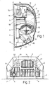
- Fig. 1 is a lateral elevation of the hand dryer in question with a part of its body corresponding to a cover being shown in a sectional view; and
- Fig. 2 illustrates a plan-view from the bottom of said dryer.
-
- According to these Figures the hand dryer being shown in them comprises a
body 1 being made up of a vertical,flat base 2 being provided to be secured to the corresponding wall P and having fitted and/or secured to its front surface the members being innerly comprised by the dryer, and acover 3 being arranged on these latter members and for such a purpose being fitted at its assembly opening to the contour of thebase 2 and being secured to this latter atpredetermined locations 4. - Among the above-mentioned members there is the motor-blower-
resistance assembly 5 being provided to suction the air at ambient temperature throughopenings 6 being provided at the lower portion of thecover 3 and being adjacent to this latter's assembly opening, another opening 7 being provided next to saidopenings 6 and in a forwardly positioned relationship with respect to them, said motor-blower-resistance assembly being as well provided to expel the hot air through aduct 8 and through said opening 7, said duct being connected to this latter opening and to the outlet of thevolute 9, this latter being secured to thebase 2 and having installed in its inside theresistance 10 and the blower (not being visible in the drawings) of the motor-blower-resistance assembly 5. - The
body 1 of the dryer does innerly comprise agrating 11 being fitted to theopenings resistance 10 is housed in one of the air inlet openings 9' of thevolute 9, in such a way that the blower suctions air through said inlet and expels said air once heated towardsduct 8, themotor 12 being externally fitted behind the other opening of saidvolute 9. - Also installed on the
base 2 is a printedcircuit board 13 comprising means such as various components particularly being amicrocontroller 17 andelectromechanical relays resistance assembly 5, themicrocontroller 17 incorporating a special software having been previously stored in it, the printedcircuit board 13 through said microcontroller and two (14 and 15) of the relays automatically regulating the outflowing air temperature once asensor 18 being provided in the dryer and being for example fitted to said printedcircuit board 13 has sensed the ambient air temperature. - The printed
circuit board 13 does as well limit through the above-mentioned components namely being themicrocontroller 17 and therelays resistance assembly 5 can be kept in continuous operation, and through another of these very components totally disconnects the dryer if themotor 12 is out of order. - By means of these
very components circuit board 13 prevents the activation of the dryer when undesirable, stationary elements not corresponding to the hands of a possible user are being present in front of the air outlet opening 7 of the dryer, this latter as well comprising adetector 19 being installed in its inside in front of asuitable opening 2 being provided in thecover 3 next to theaforesaid opening 7, said detector being apt to notify the printedcircuit board 13 of the presence of said elements.
Claims (3)
- A hand dryer comprising a body (1) having installed in its inside a motor-blower-resistance assembly (5) suctioning air from an inlet (6) being provided in said body and expelling said air once heated through an outlet (7) also being provided in said body; characterized in that the motor-blower-resistance assembly (5) is controlled by means (14, 15, 16 and 17) belonging to a printed circuit board (13) being also installed in the inside of the body (1) of the dryer, said means automatically regulating the outflowing air temperature as per the sensing of the ambient temperature being carried out by a sensor (18) being provided in said body.
- A hand dryer as per claim 1, characterized in that the printed circuit board (13) comprises means (14, 15, 16 and 17) which upon receiving the signal from a detector (19) being provided in the body (1) of the dryer prevent the dryer from being activated by the presence in front of its air outlet (7) of undesirable, stationary elements that when sensed would otherwise act as misleading targets.
- A hand dryer as per claim 1, characterized in that the printed circuit board (13) comprises means (14, 15, 16 and 17) being provided to totally disconnect the dryer if the electric motor (12) is out of order and to limit the time during which said dryer can be kept in continuous operation each time when used.
Applications Claiming Priority (2)
| Application Number | Priority Date | Filing Date | Title |
|---|---|---|---|
| ES200101028 | 2001-04-20 | ||
| ES200101028A ES2190873B1 (en) | 2001-04-20 | 2001-04-20 | HAND DRYER. |
Publications (3)
| Publication Number | Publication Date |
|---|---|
| EP1250879A2 true EP1250879A2 (en) | 2002-10-23 |
| EP1250879A3 EP1250879A3 (en) | 2003-11-12 |
| EP1250879B1 EP1250879B1 (en) | 2009-10-21 |
Family
ID=8497623
Family Applications (1)
| Application Number | Title | Priority Date | Filing Date |
|---|---|---|---|
| EP02380074A Expired - Lifetime EP1250879B1 (en) | 2001-04-20 | 2002-04-04 | A hand dryer |
Country Status (4)
| Country | Link |
|---|---|
| EP (1) | EP1250879B1 (en) |
| AT (1) | ATE446039T1 (en) |
| DE (1) | DE60234069D1 (en) |
| ES (2) | ES2190873B1 (en) |
Cited By (1)
| Publication number | Priority date | Publication date | Assignee | Title |
|---|---|---|---|---|
| US7946055B2 (en) * | 2005-07-30 | 2011-05-24 | Dyson Technology Limited | Dryer |
Families Citing this family (5)
| Publication number | Priority date | Publication date | Assignee | Title |
|---|---|---|---|---|
| GB0515750D0 (en) | 2005-07-30 | 2005-09-07 | Dyson Technology Ltd | Drying apparatus |
| GB0515754D0 (en) | 2005-07-30 | 2005-09-07 | Dyson Technology Ltd | Drying apparatus |
| GB2428569B (en) | 2005-07-30 | 2009-04-29 | Dyson Technology Ltd | Dryer |
| GB0515749D0 (en) | 2005-07-30 | 2005-09-07 | Dyson Technology Ltd | Drying apparatus |
| GB2434094A (en) | 2006-01-12 | 2007-07-18 | Dyson Technology Ltd | Drying apparatus with sound-absorbing material |
Citations (2)
| Publication number | Priority date | Publication date | Assignee | Title |
|---|---|---|---|---|
| GB2084012A (en) * | 1980-08-12 | 1982-04-07 | Smiths Industries Ltd | Automatic hand dryer |
| EP0329171A1 (en) * | 1988-02-19 | 1989-08-23 | Sloan Valve Company | Automatic hand dryer |
Family Cites Families (4)
| Publication number | Priority date | Publication date | Assignee | Title |
|---|---|---|---|---|
| JPH0451925A (en) * | 1990-06-15 | 1992-02-20 | Kyushu Electric Power Co Inc | Control method for dryer using hot air and temperature of hot air |
| JPH04215729A (en) * | 1990-12-12 | 1992-08-06 | Inax Corp | Control method for warm-air wash stand |
| JPH10113305A (en) * | 1996-10-15 | 1998-05-06 | Matsushita Seiko Co Ltd | Hand drier |
| GB2332145B (en) * | 1997-11-06 | 2002-02-20 | Airdri Ltd | Dryer |
-
2001
- 2001-04-20 ES ES200101028A patent/ES2190873B1/en not_active Expired - Fee Related
-
2002
- 2002-04-04 DE DE60234069T patent/DE60234069D1/en not_active Expired - Lifetime
- 2002-04-04 ES ES02380074T patent/ES2335270T3/en not_active Expired - Lifetime
- 2002-04-04 EP EP02380074A patent/EP1250879B1/en not_active Expired - Lifetime
- 2002-04-04 AT AT02380074T patent/ATE446039T1/en not_active IP Right Cessation
Patent Citations (2)
| Publication number | Priority date | Publication date | Assignee | Title |
|---|---|---|---|---|
| GB2084012A (en) * | 1980-08-12 | 1982-04-07 | Smiths Industries Ltd | Automatic hand dryer |
| EP0329171A1 (en) * | 1988-02-19 | 1989-08-23 | Sloan Valve Company | Automatic hand dryer |
Cited By (1)
| Publication number | Priority date | Publication date | Assignee | Title |
|---|---|---|---|---|
| US7946055B2 (en) * | 2005-07-30 | 2011-05-24 | Dyson Technology Limited | Dryer |
Also Published As
| Publication number | Publication date |
|---|---|
| ES2190873A1 (en) | 2003-08-16 |
| ATE446039T1 (en) | 2009-11-15 |
| EP1250879B1 (en) | 2009-10-21 |
| DE60234069D1 (en) | 2009-12-03 |
| ES2190873B1 (en) | 2005-08-01 |
| ES2335270T3 (en) | 2010-03-24 |
| EP1250879A3 (en) | 2003-11-12 |
Similar Documents
| Publication | Publication Date | Title |
|---|---|---|
| JP5792909B1 (en) | Drying equipment | |
| EP1467154A3 (en) | Heating cooker | |
| EP1250879A2 (en) | A hand dryer | |
| JP5164899B2 (en) | Electromagnetic induction heating cooker | |
| EP1250878B1 (en) | A hand dryer | |
| JP2010043753A (en) | Cooker | |
| GB2340010A (en) | Combined microwave oven and extractor hood | |
| JPH02219917A (en) | Device for supporting control means for domestic electrified product | |
| CN105358023A (en) | Dust collection device | |
| JP2008229152A (en) | Compound cooker | |
| US20100031949A1 (en) | Fan apparency arrangement for an appliance | |
| US6748163B2 (en) | Electric heater with dual overheat limits | |
| EP2098731A2 (en) | Condensate pump | |
| JP2018183632A (en) | Drying device | |
| JP2016140753A (en) | Drying device | |
| GB1602115A (en) | Hot air driers | |
| GB2217592A (en) | Air heated mirror | |
| JP2018043161A (en) | Drying device | |
| EP4276363A1 (en) | An exhaust hood with improved automatic operation performance | |
| CN214231014U (en) | Food processor | |
| KR970011181B1 (en) | Hood for microwave oven | |
| JP3895969B2 (en) | Cooker | |
| JP2006346478A (en) | Thermal cooker | |
| KR100551774B1 (en) | Over The Range | |
| AU3933199A (en) | Improvements to ultracompact air extractors for bathrooms |
Legal Events
| Date | Code | Title | Description |
|---|---|---|---|
| PUAI | Public reference made under article 153(3) epc to a published international application that has entered the european phase |
Free format text: ORIGINAL CODE: 0009012 |
|
| AK | Designated contracting states |
Kind code of ref document: A2 Designated state(s): AT BE CH CY DE DK ES FI FR GB GR IE IT LI LU MC NL PT SE TR |
|
| AX | Request for extension of the european patent |
Free format text: AL;LT;LV;MK;RO;SI |
|
| PUAL | Search report despatched |
Free format text: ORIGINAL CODE: 0009013 |
|
| AK | Designated contracting states |
Kind code of ref document: A3 Designated state(s): AT BE CH CY DE DK ES FI FR GB GR IE IT LI LU MC NL PT SE TR |
|
| AX | Request for extension of the european patent |
Extension state: AL LT LV MK RO SI |
|
| 17P | Request for examination filed |
Effective date: 20040312 |
|
| AKX | Designation fees paid |
Designated state(s): AT BE CH CY DE DK ES FI FR GB GR IE IT LI LU MC NL PT SE TR |
|
| 17Q | First examination report despatched |
Effective date: 20061127 |
|
| GRAP | Despatch of communication of intention to grant a patent |
Free format text: ORIGINAL CODE: EPIDOSNIGR1 |
|
| GRAS | Grant fee paid |
Free format text: ORIGINAL CODE: EPIDOSNIGR3 |
|
| GRAA | (expected) grant |
Free format text: ORIGINAL CODE: 0009210 |
|
| AK | Designated contracting states |
Kind code of ref document: B1 Designated state(s): AT BE CH CY DE DK ES FI FR GB GR IE IT LI LU MC NL PT SE TR |
|
| REG | Reference to a national code |
Ref country code: GB Ref legal event code: FG4D |
|
| REG | Reference to a national code |
Ref country code: CH Ref legal event code: EP |
|
| REG | Reference to a national code |
Ref country code: IE Ref legal event code: FG4D |
|
| REF | Corresponds to: |
Ref document number: 60234069 Country of ref document: DE Date of ref document: 20091203 Kind code of ref document: P |
|
| REG | Reference to a national code |
Ref country code: ES Ref legal event code: FG2A Ref document number: 2335270 Country of ref document: ES Kind code of ref document: T3 |
|
| NLV1 | Nl: lapsed or annulled due to failure to fulfill the requirements of art. 29p and 29m of the patents act | ||
| PG25 | Lapsed in a contracting state [announced via postgrant information from national office to epo] |
Ref country code: FI Free format text: LAPSE BECAUSE OF FAILURE TO SUBMIT A TRANSLATION OF THE DESCRIPTION OR TO PAY THE FEE WITHIN THE PRESCRIBED TIME-LIMIT Effective date: 20091021 Ref country code: SE Free format text: LAPSE BECAUSE OF FAILURE TO SUBMIT A TRANSLATION OF THE DESCRIPTION OR TO PAY THE FEE WITHIN THE PRESCRIBED TIME-LIMIT Effective date: 20091021 Ref country code: PT Free format text: LAPSE BECAUSE OF FAILURE TO SUBMIT A TRANSLATION OF THE DESCRIPTION OR TO PAY THE FEE WITHIN THE PRESCRIBED TIME-LIMIT Effective date: 20100222 |
|
| PG25 | Lapsed in a contracting state [announced via postgrant information from national office to epo] |
Ref country code: AT Free format text: LAPSE BECAUSE OF FAILURE TO SUBMIT A TRANSLATION OF THE DESCRIPTION OR TO PAY THE FEE WITHIN THE PRESCRIBED TIME-LIMIT Effective date: 20091021 Ref country code: BE Free format text: LAPSE BECAUSE OF FAILURE TO SUBMIT A TRANSLATION OF THE DESCRIPTION OR TO PAY THE FEE WITHIN THE PRESCRIBED TIME-LIMIT Effective date: 20091021 |
|
| PG25 | Lapsed in a contracting state [announced via postgrant information from national office to epo] |
Ref country code: DK Free format text: LAPSE BECAUSE OF FAILURE TO SUBMIT A TRANSLATION OF THE DESCRIPTION OR TO PAY THE FEE WITHIN THE PRESCRIBED TIME-LIMIT Effective date: 20091021 |
|
| PLBE | No opposition filed within time limit |
Free format text: ORIGINAL CODE: 0009261 |
|
| STAA | Information on the status of an ep patent application or granted ep patent |
Free format text: STATUS: NO OPPOSITION FILED WITHIN TIME LIMIT |
|
| 26N | No opposition filed |
Effective date: 20100722 |
|
| PG25 | Lapsed in a contracting state [announced via postgrant information from national office to epo] |
Ref country code: GR Free format text: LAPSE BECAUSE OF FAILURE TO SUBMIT A TRANSLATION OF THE DESCRIPTION OR TO PAY THE FEE WITHIN THE PRESCRIBED TIME-LIMIT Effective date: 20100122 |
|
| PG25 | Lapsed in a contracting state [announced via postgrant information from national office to epo] |
Ref country code: MC Free format text: LAPSE BECAUSE OF NON-PAYMENT OF DUE FEES Effective date: 20100430 |
|
| REG | Reference to a national code |
Ref country code: CH Ref legal event code: PL |
|
| GBPC | Gb: european patent ceased through non-payment of renewal fee |
Effective date: 20100404 |
|
| REG | Reference to a national code |
Ref country code: FR Ref legal event code: ST Effective date: 20101230 |
|
| PG25 | Lapsed in a contracting state [announced via postgrant information from national office to epo] |
Ref country code: IE Free format text: LAPSE BECAUSE OF NON-PAYMENT OF DUE FEES Effective date: 20100404 |
|
| PG25 | Lapsed in a contracting state [announced via postgrant information from national office to epo] |
Ref country code: CH Free format text: LAPSE BECAUSE OF NON-PAYMENT OF DUE FEES Effective date: 20100430 Ref country code: LI Free format text: LAPSE BECAUSE OF NON-PAYMENT OF DUE FEES Effective date: 20100430 |
|
| PG25 | Lapsed in a contracting state [announced via postgrant information from national office to epo] |
Ref country code: GB Free format text: LAPSE BECAUSE OF NON-PAYMENT OF DUE FEES Effective date: 20100404 |
|
| PGFP | Annual fee paid to national office [announced via postgrant information from national office to epo] |
Ref country code: IT Payment date: 20120328 Year of fee payment: 11 |
|
| PG25 | Lapsed in a contracting state [announced via postgrant information from national office to epo] |
Ref country code: FR Free format text: LAPSE BECAUSE OF NON-PAYMENT OF DUE FEES Effective date: 20100430 |
|
| PG25 | Lapsed in a contracting state [announced via postgrant information from national office to epo] |
Ref country code: CY Free format text: LAPSE BECAUSE OF FAILURE TO SUBMIT A TRANSLATION OF THE DESCRIPTION OR TO PAY THE FEE WITHIN THE PRESCRIBED TIME-LIMIT Effective date: 20091021 |
|
| PG25 | Lapsed in a contracting state [announced via postgrant information from national office to epo] |
Ref country code: LU Free format text: LAPSE BECAUSE OF NON-PAYMENT OF DUE FEES Effective date: 20100404 Ref country code: NL Free format text: LAPSE BECAUSE OF FAILURE TO SUBMIT A TRANSLATION OF THE DESCRIPTION OR TO PAY THE FEE WITHIN THE PRESCRIBED TIME-LIMIT Effective date: 20091021 |
|
| PG25 | Lapsed in a contracting state [announced via postgrant information from national office to epo] |
Ref country code: TR Free format text: LAPSE BECAUSE OF FAILURE TO SUBMIT A TRANSLATION OF THE DESCRIPTION OR TO PAY THE FEE WITHIN THE PRESCRIBED TIME-LIMIT Effective date: 20091021 |
|
| PGFP | Annual fee paid to national office [announced via postgrant information from national office to epo] |
Ref country code: DE Payment date: 20120629 Year of fee payment: 11 |
|
| REG | Reference to a national code |
Ref country code: DE Ref legal event code: R082 Ref document number: 60234069 Ref country code: DE Ref legal event code: R082 Ref document number: 60234069 Country of ref document: DE Representative=s name: , |
|
| PG25 | Lapsed in a contracting state [announced via postgrant information from national office to epo] |
Ref country code: DE Free format text: LAPSE BECAUSE OF NON-PAYMENT OF DUE FEES Effective date: 20131101 |
|
| REG | Reference to a national code |
Ref country code: DE Ref legal event code: R119 Ref document number: 60234069 Country of ref document: DE Effective date: 20131101 |
|
| PG25 | Lapsed in a contracting state [announced via postgrant information from national office to epo] |
Ref country code: IT Free format text: LAPSE BECAUSE OF NON-PAYMENT OF DUE FEES Effective date: 20130404 |
|
| PGFP | Annual fee paid to national office [announced via postgrant information from national office to epo] |
Ref country code: ES Payment date: 20210528 Year of fee payment: 20 |
|
| REG | Reference to a national code |
Ref country code: ES Ref legal event code: FD2A Effective date: 20220629 |
|
| PG25 | Lapsed in a contracting state [announced via postgrant information from national office to epo] |
Ref country code: ES Free format text: LAPSE BECAUSE OF EXPIRATION OF PROTECTION Effective date: 20220405 |