EP1250501B1 - Connecting element for tubular elements, especially handrails - Google Patents
Connecting element for tubular elements, especially handrails Download PDFInfo
- Publication number
- EP1250501B1 EP1250501B1 EP01946916A EP01946916A EP1250501B1 EP 1250501 B1 EP1250501 B1 EP 1250501B1 EP 01946916 A EP01946916 A EP 01946916A EP 01946916 A EP01946916 A EP 01946916A EP 1250501 B1 EP1250501 B1 EP 1250501B1
- Authority
- EP
- European Patent Office
- Prior art keywords
- connecting element
- area
- element according
- counterpart
- thread
- Prior art date
- Legal status (The legal status is an assumption and is not a legal conclusion. Google has not performed a legal analysis and makes no representation as to the accuracy of the status listed.)
- Expired - Lifetime
Links
- 230000007704 transition Effects 0.000 claims description 17
- 238000004519 manufacturing process Methods 0.000 description 4
- 238000003780 insertion Methods 0.000 description 2
- 230000037431 insertion Effects 0.000 description 2
- 230000009471 action Effects 0.000 description 1
- 230000015572 biosynthetic process Effects 0.000 description 1
- 230000001010 compromised effect Effects 0.000 description 1
- 230000001419 dependent effect Effects 0.000 description 1
- 238000000926 separation method Methods 0.000 description 1
- 230000007480 spreading Effects 0.000 description 1
- 230000008719 thickening Effects 0.000 description 1
- 230000003313 weakening effect Effects 0.000 description 1
Images
Classifications
-
- E—FIXED CONSTRUCTIONS
- E04—BUILDING
- E04F—FINISHING WORK ON BUILDINGS, e.g. STAIRS, FLOORS
- E04F11/00—Stairways, ramps, or like structures; Balustrades; Handrails
- E04F11/18—Balustrades; Handrails
- E04F11/181—Balustrades
-
- F—MECHANICAL ENGINEERING; LIGHTING; HEATING; WEAPONS; BLASTING
- F16—ENGINEERING ELEMENTS AND UNITS; GENERAL MEASURES FOR PRODUCING AND MAINTAINING EFFECTIVE FUNCTIONING OF MACHINES OR INSTALLATIONS; THERMAL INSULATION IN GENERAL
- F16B—DEVICES FOR FASTENING OR SECURING CONSTRUCTIONAL ELEMENTS OR MACHINE PARTS TOGETHER, e.g. NAILS, BOLTS, CIRCLIPS, CLAMPS, CLIPS OR WEDGES; JOINTS OR JOINTING
- F16B7/00—Connections of rods or tubes, e.g. of non-circular section, mutually, including resilient connections
- F16B7/18—Connections of rods or tubes, e.g. of non-circular section, mutually, including resilient connections using screw-thread elements
Definitions
- the invention relates to a connecting element referred to in the preamble of claim 1.
- Art Such fasteners are used for connection of tubular elements in which no media flow is provided through the tubes, such as. B. in handrails of a railing.
- the tubular formation of individual handrail elements is rather due to the associated material and weight savings and increased stability. This poses the problem of not having to individually adapt the individual handrail elements to the respective building conditions, but to be able to use prefabricated, standardized elements which can be connected to one another as required.
- these connections must be extremely resilient, since in some cases large forces act on them.
- the connecting elements should not be as visible as possible in the final assembly state.
- Object of the present invention is to provide a connecting element of the type mentioned above, which allows a safe, but rotatable and thus optimally adaptable to building structures connection between handrail elements.
- the fasteners should be virtually invisible from the outside.
- the inserted into the pipe opening of a handrail element insert is at least two parts.
- An outer retaining bush is fixed in the pipe to be connected.
- the determination can be made by jamming, screwing, latching or the like.
- an inner counterpart is used, which in turn has at least three functionally different areas.
- the junction facing area an internal thread is provided, in which the threaded bolt of the adjacent handrail or transition element can be screwed.
- the front area itself is not fixed to the retaining bush. This determination is made rather on a rear portion of the counterpart.
- This determination is made rather on a rear portion of the counterpart.
- z can z.
- a press fit or a thread may be provided, the orientation of which is preferably opposite to the orientation of the thread in the front region. It is crucial, the counterpart with its rear area so on the Specify retaining bush that the threaded bolt of the adjacent handrail or transition element can be screwed into the thread of the front, even not fixed to the retaining bush portion of the counterpart. It makes particularly sense to let the thread run out in the front of the counterpart in a hole whose diameter corresponds approximately to the thread core diameter. In this sense, "screwing" the threaded bolt means a transition from pure positive engagement to a positive and non-positive connection. The determination of the rear portion of the counterpart on the retaining sleeve must be designed to be strong enough to compensate for the forces occurring.
- a special transition region is provided between the front and rear region of the counterpart, which breaks at a well-defined location when subjected to increased torsional force.
- the predetermined breaking property of the transition region can be z. B. be realized by particularly thin material thickness, preforms or the like. This breaks the transition area after the threaded bolt is screwed in the front part of the counterpart, its firm connection with the retaining sleeve is released. At the same time the front part of the counterpart remains firmly connected to the threaded bolt. The rotational mobility of the two connected handrail elements is restored.
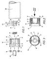
- FIGS. 1-3 shows a particularly advantageous embodiment of a connecting element according to the invention and areas of the subsequent, to be connected handrail or transition elements in a clear exploded view.
- the actual connecting element consists of the retaining sleeve 10 and the counterpart 20.
- the reference numeral 30 denotes a tubular handrail element.
- the object of the connecting element according to the invention is to connect the first handrail element 30 with a second handrail or transition element, of which only parts of a threaded bolt 40 are shown. It is conceivable that the threaded bolt 40 is fixed in the second handrail or transition element by clamping or screwing devices of known type or otherwise. However, the threaded bolt 40 may also be part of a special transition element, for. B. be a ball joint element.
- the counterpart 20 Before mounting the handrail, the counterpart 20 is introduced into the receiving chamber 11 of the retaining sleeve 10. The determination takes place via the rear portion 23 of the counterpart 20.
- a press fit 27 is provided for this purpose.
- a flange 28 defines the insertion depth into the receiving chamber 11.
- the front portion 24 of the counterpart 20 has a slightly smaller diameter, so that there is no direct attachment to the support sleeve 10.
- the counterpart 20 is penetrated by a through hole, which has an internal thread 24 in the front region 21.
- the thread 24 is adapted to the thread of the threaded bolt 40. If the counterpart 20 is fixed in the receiving chamber 11 of the holding bush 10, the entire insert can be introduced into the tubular handrail element 30.
- a flange 15 preferably defines a defined insertion depth.
- the determination of the insert 10/20 in the tube 30 is carried out in the embodiment shown by jamming. For this purpose, radially outward and axially rearward expansion slots 12 are provided in the retaining sleeve 10.
- the adjacent handrail or transition element is connected by its threaded bolt 40 inserted through the through hole 16 in the receiving chamber 11 of the retaining sleeve 10 and screwed into the thread 24 in the front portion 21 of the counterpart 20 becomes.
- the diameter of the thread 24 and the connecting hole 25 are chosen so that the purely positive connection of the thread 24 and 40 merges into a frictional connection.
- the threaded bolt is then screwed tight. Further action of torsional forces leads to the intended breakage of the counterpart 20 in the region 22, in particular at the predetermined breaking surface 26.
- the connected handrail elements are thus rotationally movable against each other.
- a relative axial mobility of the connected handrail elements is not possible because the diameter of the through hole 16, which limits the receiving chamber 11 of the retaining sleeve 10 forward, is smaller than the diameter of the front portion 21 of the counterpart 20. Only a very small, by manufacturing tolerances conditional, axial mobility is still present. At the in Fig. 1 shown embodiment, this residual mobility is reliably prevented by the use of the compensating spring 19, which pulls the connected elements within the tolerances in each other.
- Handrails connected in this way can be adapted as desired to the angles of individual building structures without their safety being compromised.
- the predetermined breaking region 22 of the counterpart 20 is realized in the embodiment shown by a region of reduced material thickness, which defines an exact, annular predetermined breaking surface.
- any other measure locally weakening the material in a defined manner is equally applicable.
- a ring of holes could be provided.
- the determination of the retaining sleeve 10 in the tube 30 must not be made in the manner explained by jamming.
- a screw or locking connection is also conceivable.
- the thread is preferably oriented in the same direction as the threaded bolt 40. The disadvantage here, however, is the more complex production of the tubes 30, would have to be cut into the internal thread.
- the front end face of the retaining bush is provided with a socket-like recess 17. This is particularly advantageous when spherical transition or end pieces to be connected with its threaded bolt 40 to the pipe member 30.
- the threaded bolt 40 of the illustrated embodiment can be thought of as being reduced to a substantially cylindrical pin with side pins which engage in a female thread 24 reduced to less than a single thread like a bayonet catch. Also in this embodiment, the advantageous transition from form to adhesion can be made possible by known measures.
- the connecting elements according to the invention are suitable for the connection of any kind of at least partially tubular and non-media-carrying elements.
Description
Die Erfindung bezieht sich auf ein Verbindungselement der im Oberbegriff von Anspruch 1 genannten Art. Derartige Verbindungselemente werden eingesetzt zur Verbindung von rohrartigen Elementen, bei denen kein Medienfluß durch die Rohre vorgesehen ist, wie z. B. bei Handläufen eines Geländers. Die rohrartige Ausbildung einzelner Handlaufelemente ist vielmehr auf die damit verbundene Material- und Gewichtseinsparung sowie die erhöhte Stabilität zurückzuführen. Dabei stellt sich das Problem, die einzelnen Handlaufelemente möglichst nicht an die jeweiligen Gebäudegegebenheiten individuell anpassen zu müssen, sondern vorgefertigte, normierte Elemente verwenden zu können, die je nach Bedarf miteinander verbunden werden können. Diese Verbindungen müssen aus Sicherheitsgründen ausgesprochen belastbar sein, da zum Teil große Kräfte auf sie wirken. Aus ästhetischen Gründen sollen die Verbindungselemente im Montageendzustand möglichst nicht sichtbar sein.The invention relates to a connecting element referred to in the preamble of claim 1. Art Such fasteners are used for connection of tubular elements in which no media flow is provided through the tubes, such as. B. in handrails of a railing. The tubular formation of individual handrail elements is rather due to the associated material and weight savings and increased stability. This poses the problem of not having to individually adapt the individual handrail elements to the respective building conditions, but to be able to use prefabricated, standardized elements which can be connected to one another as required. For safety reasons, these connections must be extremely resilient, since in some cases large forces act on them. For aesthetic reasons, the connecting elements should not be as visible as possible in the final assembly state.
Dies führte in der Vergangenheit zu Verbindungselementen, die wenigstens bereichsweise in die Rohre der Handläufe einsteckbar und dort auf verschiedene Weise, z. B. durch Verschrauben, Verklemmen, Verrasten etc., festlegbar waren. Solche Verbindungselemente weisen in der Regel ein Zentralgewinde auf, in welches ein Gewindebolzen des benachbarten Handlaufelements bzw. eines Übergangselementes eindrehbar ist. Dieser Stand der Technik weist den erheblichen Nachteil auf, daß die verbundenen Elemente nach dem Festziehen des Gewindebolzens nicht mehr gegeneinander rotationsbeweglich sind. Dies führt zu Schwierigkeiten bei der Anpassung des Geländers an die individuelle Strukturen eines Gebäudes. Um, insbesondere bei winklig miteinander verbundenen Handlaufelementen die volle Anpaßbarkeit an Gebäudestrukturen zu gewährleisten, müssen die gattungsbildenden Verbindungselemente auch nach dem Festziehen des Gewindebolzens lösbar, einstellbar und von außen wieder festlegbar gestaltet sein. Die Möglichkeit eines Zugriffs von außen erfordert jedoch stets von außen sichtbare Elemente, was, wie bereits erwähnt, aus ästhetischen Gründen nicht wünschenswert ist. Eine besonders kleine, unauffällige Gestaltung der von außen sichtbaren Elemente, würde sich jedoch in verringerter Belastbarkeit, d. h. geringerer Sicherheit niederschlagen.This led in the past to fasteners that at least partially plugged into the tubes of the handrails and there in various ways, eg. B. by screwing, jamming, latching, etc., were fixed. Such connecting elements generally have a central thread into which a threaded bolt of the adjacent handrail element or a transition element can be screwed. This prior art has the considerable disadvantage that the connected elements are no longer mutually rotationally movable after tightening the threaded bolt. This leads to difficulties in adapting the railing to the individual structures of a building. To, in particular at an angle interconnected handrail elements To ensure the full adaptability to building structures, the generic type fasteners must be designed releasable after the tightening of the threaded bolt, adjustable and fixed again from the outside. However, the possibility of access from the outside always requires externally visible elements, which, as already mentioned, is not desirable for aesthetic reasons. A particularly small, inconspicuous design of the externally visible elements, but would be reflected in reduced resilience, ie lower security.
Aufgabe der vorliegenden Erfindung ist es, ein Verbindungselement der oben genannten Art zu schaffen, das eine sichere, jedoch rotationsbewegliche und somit optimal an Gebäudestrukturen anpaßbare Verbindung zwischen Handlaufelementen ermöglicht. Die Verbindungselemente sollten darüber hinaus von außen praktisch nicht sichtbar sein.Object of the present invention is to provide a connecting element of the type mentioned above, which allows a safe, but rotatable and thus optimally adaptable to building structures connection between handrail elements. In addition, the fasteners should be virtually invisible from the outside.
Diese Aufgabe wird gelöst durch die Merkmale des kennzeichnenden Teils von Anspruch 1. Diesen kommt im Einzelnen folgende Bedeutung zu. Der in die Rohröffnung eines Handlaufelementes einzuführende Einsatz ist wenigstens zweiteilig ausgebildet. Eine äußere Haltebuchse wird in dem zu verbindenden Rohr festgelegt. Die Festlegung kann durch Verklemmen, Verschrauben, Verrasten oder ähnliches erfolgen. In die Haltebuchse ist ein inneres Gegenstück eingesetzt, das seinerseits wenigstens drei funktionell unterschiedliche Bereiche aufweist. In einem vorderen, der Verbindungsstelle zugewandten Bereich ist ein Innengewinde vorgesehen, in welches der Gewindebolzen des benachbarten Handlauf- oder Übergangselementes eingedreht werden kann. Der vordere Bereich selbst ist dabei nicht an der Haltebuchse festgelegt. Diese Festlegung erfolgt vielmehr über einen hinteren Bereich des Gegenstücks. Hier kann z. B. eine Preßpassung oder ein Gewinde vorgesehen sein, dessen Orientierung vorzugsweise der Orientierung des Gewindes im vorderen Bereich entgegengesetzt ist. Entscheidend ist es, das Gegenstück mit seinem hinteren Bereich so an der Haltebuchse festzulegen, daß der Gewindebolzen des benachbarten Handlauf- oder Übergangselementes in das Gewinde des vorderen, selbst nicht an der Haltebuchse festgelegten Bereiches des Gegenstückes festgeschraubt werden kann. Besonders sinnvoll ist es dabei, das Gewinde im vorderen Bereich des Gegenstücks in eine Bohrung auslaufen zu lassen, deren Durchmesser in etwa dem Gewindekerndurchmesser entspricht. In diesem Sinne bedeutet "festschrauben" des Gewindebolzens einen Übergang vom reinen Formschluß zu einer form- und kraftschlüssigen Verbindung. Die Festlegung des hinteren Bereiches des Gegenstücks an der Haltebuchse muß entsprechend stark ausgelegt sein, um die auftretenden Kräfte zu kompensieren.This object is achieved by the features of the characterizing part of claim 1. These have the following significance. The inserted into the pipe opening of a handrail element insert is at least two parts. An outer retaining bush is fixed in the pipe to be connected. The determination can be made by jamming, screwing, latching or the like. In the retaining sleeve, an inner counterpart is used, which in turn has at least three functionally different areas. In a front, the junction facing area an internal thread is provided, in which the threaded bolt of the adjacent handrail or transition element can be screwed. The front area itself is not fixed to the retaining bush. This determination is made rather on a rear portion of the counterpart. Here can z. Example, a press fit or a thread may be provided, the orientation of which is preferably opposite to the orientation of the thread in the front region. It is crucial, the counterpart with its rear area so on the Specify retaining bush that the threaded bolt of the adjacent handrail or transition element can be screwed into the thread of the front, even not fixed to the retaining bush portion of the counterpart. It makes particularly sense to let the thread run out in the front of the counterpart in a hole whose diameter corresponds approximately to the thread core diameter. In this sense, "screwing" the threaded bolt means a transition from pure positive engagement to a positive and non-positive connection. The determination of the rear portion of the counterpart on the retaining sleeve must be designed to be strong enough to compensate for the forces occurring.
Erfindungsgemäß ist zwischen dem vorderen und hinteren Bereich des Gegenstücks ein besonderer Übergangsbereich vorgesehen, der bei Einwirkung erhöhter Torsionskraft an wohldefinierter Stelle bricht. Die Sollbrucheigenschaft des Übergangsbereiches kann z. B. durch besonders dünne Materialstärke, Preforationen oder ähnliches realisiert werden. Bricht nämlich der Übergangsbereich nachdem der Gewindebolzen im vorderen Teil des Gegenstücks festgeschraubt ist, wird dessen feste Verbindung mit der Haltebuchse gelöst. Gleichzeitig bleibt der vordere Teil des Gegenstücks fest mit dem Gewindebolzen verbunden. Die Rotationsbeweglichkeit der beiden verbundenen Handlaufelemente ist so wieder hergestellt. Eine axialen Beweglichkeit wird jedoch durch den fest auf dem Gewindebolzen sitzenden und als Verdickung wirkenden vorderen Teil des Gegenstücks wirksam verhindert, sofern die Öffnung in der Stirnseite der Haltebuchse, durch welche der Gewindebolzen eingeführt wurde, kleiner ist als der Durchmesser dieses vorderen Gegenstück-Bereiches. Auf diese Weise wird eine axial stabile aber rotationsbewegliche Verbindung zwischen zwei Handlaufelementen realisiert.According to the invention, a special transition region is provided between the front and rear region of the counterpart, which breaks at a well-defined location when subjected to increased torsional force. The predetermined breaking property of the transition region can be z. B. be realized by particularly thin material thickness, preforms or the like. This breaks the transition area after the threaded bolt is screwed in the front part of the counterpart, its firm connection with the retaining sleeve is released. At the same time the front part of the counterpart remains firmly connected to the threaded bolt. The rotational mobility of the two connected handrail elements is restored. An axial mobility is effectively prevented by the seated on the threaded bolt and acting as a thickening front part of the counterpart, provided that the opening in the end face of the retaining sleeve through which the threaded bolt was inserted, is smaller than the diameter of this front counterpart area. In this way, an axially stable but rotationally movable connection between two handrail elements is realized.
Besonders vorteilhaft ist es, zwischen der Haltebuchse und dem Gegenstück eine Ausgleichsfeder vorzusehen, die fertigungsbedingte Axialtoleranzen ausgleicht. Auf diese Weise lassen sich die einzelnen Elemente mit größeren Fertigungstoleranzen, d. h. kostengünstiger, herstellen, ohne daß aufgrund einer verbleibenden axialen Restbeweglichkeit der Eindruck einer unsicheren Verbindung entsteht.It is particularly advantageous to provide a compensation spring between the retaining bush and the counterpart, the axial tolerances due to production balances. In this way, the individual elements with larger manufacturing tolerances, that is cheaper to produce without resulting in the impression of an unsafe connection due to a residual axial residual mobility.
Weitere Vorteile ergeben sich aus den übrigen Unteransprüchen, der speziellen Beschreibung sowie den Zeichnungen. Es zeigen
- Fig. 1
- eine Explosionsdarstellung einer besonders vorteilhaften Ausführungsform des erfindungsgemäßen Verbindungselementes,
- Fig. 2
- einen Schnitt durch die Haltebuchse,
- Fig. 3
- eine Draufsicht auf die Haltebuchse gemäß Richtungspfeil III in
Fig. 2 .
- Fig. 1
- an exploded view of a particularly advantageous embodiment of the connecting element according to the invention,
- Fig. 2
- a section through the retaining bush,
- Fig. 3
- a plan view of the retaining sleeve according to directional arrow III in
Fig. 2 ,
Die
Der vordere Bereich 24 des Gegenstücks 20 weist einen geringfügig kleineren Durchmesser auf, so daß hier keine direkte Festlegung an der Haltbuchse 10 erfolgt. Das Gegenstück 20 ist von einer Durchgangsbohrung durchsetzt, die im vorderen Bereich 21 ein Innengewinde 24 aufweist. Das Gewinde 24 ist dem Gewinde des Gewindebolzens 40 angepaßt. Ist das Gegenstück 20 in der Aufnahmekammer 11 der Haltebuchse 10 festgelegt, kann der gesamte Einsatz in das rohrartige Handlaufelement 30 eingebracht werden. Ein Flansch 15 legt dabei vorzugsweise eine definierte Einführtiefe fest. Die Festlegung des Einsatzes 10/20 im Rohr 30 erfolgt in dem gezeigten Ausführungsbeispiel durch Verklemmen. Hierzu sind in der Haltebuchse 10 radial außen und axial hinten Spreizschlitze 12 vorgesehen. Diese werden von Gewindebohrungen 13 durchsetzt, in welche Madenschrauben 14 einschraubbar sind. Durch Einführen der Madenschrauben 14 erfolgt eine Spreizung der Spreizschlitze 12, was zu einer kraftschlüssigen Festlegung der Haltebuchse im Rohr 30 führt. Um eventuell im Rohrinneren vorhandene Schweißnähte ausgleichen zu können, ist es vorteilhaft, eine entsprechende axiale Nut 18 in der Haltebuchse 10 vorzusehen..The
Nach Festlegung des Einsatzes 10/20 in dem Rohr 30 wird das benachbarte Handlauf- bzw. Übergangselement angeschlossen, indem sein Gewindebolzen 40 durch die Durchgangsbohrung 16 in die Aufnahmekammer 11 der Haltebuchse 10 eingeführt und in das Gewinde 24 im vorderen Bereich 21 des Gegenstücks 20 eingeschraubt wird. Vorteilhafterweise sind die Durchmesser des Gewindes 24 und der Anschlußbohrung 25 so gewählt, daß die rein formschlüssige Verbindung der Gewinde 24 und 40 in eine kraftschlüssige Verbindung übergeht. Der Gewindebolzen ist dann festgeschraubt. Weitere Einwirkung von Torsionskräften führt zum vorgesehenen Bruch des Gegenstücks 20 im Bereich 22, insbesondere an der Sollbruchfläche 26. Der vordere Bereich 21, der durch den Kraftschluß der Gewinde 24 und 40 fest mit dem Gewindebolzen 40 verbunden ist, steht nun nicht mehr in fester Verbindung mit der Haltebuchse 10. Die verbundenen Handlaufelemente sind somit gegeneinander rotationsbeweglich. Eine relative axiale Beweglichkeit der verbundenen Handlaufelemente ist jedoch nicht möglich, da der Durchmesser der Durchgangsbohrung 16, die die Aufnahmekammer 11 der Haltebuchse 10 nach vorne begrenzt, kleiner ist als der Durchmesser des vorderen Bereichs 21 des Gegenstücks 20. Lediglich eine sehr geringfügige, durch Fertigungstoleranzen bedingte, axiale Beweglichkeit ist noch gegeben. Bei dem in
Auf diese Art verbundene Handläufe können beliebig den Winkeln individueller Gebäudestrukturen angepaßt werden, ohne daß ihre Sicherheit darunter litte.Handrails connected in this way can be adapted as desired to the angles of individual building structures without their safety being compromised.
Neben der in den
Der Sollbruchbereich 22 des Gegenstücks 20 ist in der gezeigten Ausführungsform durch einen Bereich verringerter Materialstärke realisiert, der eine exakte, ringförmige Sollbruchfläche definiert. Jegliche sonstige das Material lokal auf definierte Weise schwächende Maßnahme ist jedoch ebenso anwendbar. Beispielsweise könnte ein Kranz von Bohrungen vorgesehen werden.The
Auch die Festlegung der Haltebuchse 10 in dem Rohr 30 muß nicht in der erläuterten Weise durch Verklemmen erfolgen. Eine Schraub- oder Rastverbindung ist ebenso denkbar. Das Gewinde ist dabei vorzugsweise in gleicher Richtung wie der Gewindebolzen 40 orientiert. Nachteilig hierbei ist jedoch die aufwendigere Fertigung der Rohre 30, in die Innengewinde geschnitten werden müßten.The determination of the retaining
Bei der gezeigten Ausführungsform ist die vordere Stirnfläche der Haltebuchse mit einer pfannenartigen Vertiefung 17 versehen. Dies ist besonders vorteilhaft, wenn kugelartige Übergangs- oder Endstücke mit ihrem Gewindebolzen 40 an das Rohrelement 30 angeschlossen werden sollen.In the embodiment shown, the front end face of the retaining bush is provided with a socket-
Der Gewindebolzen 40 des gezeigten Ausführungsbeispiels kann zu einem im wesentlichen zylindrischen Bolzen mit seitlichen Stiften reduziert gedacht werden, die nach Art eines Bajonettverschlusses in ein auf weniger als einen einzelnen Gewindegang reduziertes Innengewinde 24 eingreifen. Auch bei dieser Ausführungsform kann der vorteilhafte Übergang vom Form- zum Kraftschluß durch bekannte Maßnahmen ermöglicht werden.The threaded
Auch der Anwendungsbereich der Erfindung ist nicht auf Handläufe beschränkt. Vielmehr eignen sich die erfindungsgemäßen Verbindungselemente zur Verbindung jeglicher Art von wenigstens bereichsweise rohrartigen und nicht medienführenden Elementen.The scope of the invention is not limited to handrails. Rather, the connecting elements according to the invention are suitable for the connection of any kind of at least partially tubular and non-media-carrying elements.
- 1010
- Haltebuchseretaining bush
- 1111
- Aufnahmekammer in 10 für 20Recording chamber in 10 for 20
- 1212
- Spreizspaltseparation gap
- 1313
- Spreizgewindeexpanding thread
- 1414
- Madenschraubegrub screw
- 1515
- Flanschflange
- 1616
- DurchgangsbohrungThrough Hole
- 1717
- Aufnahmepfannereceiving cup
- 1818
- Nutgroove
- 1919
- Ausgleichsfederbalancing spring
- 2020
- Gegenstückcounterpart
- 2121
- vorderer Bereich von 20front area of 20
- 2222
- Übergangsbereich zwischen 21 und 23Transition area between 21 and 23
- 2323
- hinterer Bereich von 20rear area of 20
- 2424
- Gewindethread
- 2525
- Anschlußbohrungconnecting bore
- 2626
- SollbruchflächeBreaking surface
- 2727
- Preßpassungpress fit
- 2828
- Flanschflange
- 3030
- rohrartiger Handlauftubular handrail
- 4040
- Gewindebolzenthreaded bolt
Claims (10)
- Connecting element for the axial or angled connection of a first element (30), which is tubular at least in its end area, to a further element which has a threaded pin (40), with both in particular being parts of handrails,
having an insert (10/20) in the end area of the first element (30), into which the threaded pin (40) of the other element can be screwed, with the insert (10/20) being fixable in the inside of the first element (30) in the end area of said first element (30),
characterized in that
the insert (10/20) is designed as at least a two-part component, i.e. consisting of an outer retaining socket (10) with an inner receiving chamber (11) and a counterpart section (20) with a front and rear area (21, 23) within the receiving chamber (11),
with the counterpart section (20) having an internal thread (24) in its front area (21) for receiving a threaded pin (40) and having an external diameter projecting beyond the width of the front opening (16) of the receiving chamber (11)
and with the rear area (23) of said counterpart section (20) having means (27) for fixing the counterpart section (20) on the retaining socket (10), with both areas (21, 23) being connected by a transition area (22) which fractures when subjected to an increased torsional force. - Connecting element according to Claim 1, characterized in that a connecting bore (25), whose diameter corresponds approximately to the core diameter of the thread, is attached to the internal thread (24).
- Connecting element according to one of Claims 1 and 2, characterized in that the threaded pin (40) and the corresponding thread (24) interact as a type of bayonet connection.
- Connecting element according to one of Claims 1 to 3, characterized in that the rear area (23) of the counterpart section (20) has a cylindrical part area (27) which can be pressed into a corresponding recess in the retaining socket (10) to form an interference fit.
- Connecting element according to one of Claims 1 to 3, characterized in that the rear area (23) of the counterpart section (20) has an external thread by means of which it can be fixed in a corresponding internal thread of the retaining socket (10), and which has an orientation in the opposite direction to the internal thread (24) receiving the threaded pin (40), of the front area (21) of the counterpart section (20).
- Connecting element according to one of Claims 1 to 5, characterized in that the transition area (22), which fractures when exposed to increased torsional stress, has a substantially smaller material thickness than the front (21) and the rear (23) areas of the counterpart section (20).
- Connecting element according to one of Claims 1 to 6, characterized in that the retaining socket (10) has bowstring-type slots (12) in its radial outer and axial rear areas, which can be spread by screwing in screws, especially grub screws (14) into the internal threads (13) provided in the slots (12).
- Connecting element according to one of Claims 1 to 7, characterized in that the retaining socket (10) has a pan-shaped recess (17) in its front face to receive a spherical section-shaped area of the other element to be connected.
- Connecting element according to one of Claims 1 to 8, characterized in that the counterpart section (20) is spring loaded against a retaining socket (10).
- Connecting element according to one of Claims 1 to 9, characterized in that the retaining socket (10) has a groove (18) extending in an axial direction in its outer surface.
Applications Claiming Priority (3)
| Application Number | Priority Date | Filing Date | Title |
|---|---|---|---|
| DE20001350U | 2000-01-27 | ||
| DE20001350U DE20001350U1 (en) | 2000-01-27 | 2000-01-27 | Connector for tubular elements, especially handrails |
| PCT/EP2001/000805 WO2001055528A1 (en) | 2000-01-27 | 2001-01-25 | Connecting element for tubular elements, especially handrails |
Publications (2)
| Publication Number | Publication Date |
|---|---|
| EP1250501A1 EP1250501A1 (en) | 2002-10-23 |
| EP1250501B1 true EP1250501B1 (en) | 2008-09-10 |
Family
ID=7936423
Family Applications (1)
| Application Number | Title | Priority Date | Filing Date |
|---|---|---|---|
| EP01946916A Expired - Lifetime EP1250501B1 (en) | 2000-01-27 | 2001-01-25 | Connecting element for tubular elements, especially handrails |
Country Status (4)
| Country | Link |
|---|---|
| EP (1) | EP1250501B1 (en) |
| AU (1) | AU2001228491A1 (en) |
| DE (2) | DE20001350U1 (en) |
| WO (1) | WO2001055528A1 (en) |
Family Cites Families (2)
| Publication number | Priority date | Publication date | Assignee | Title |
|---|---|---|---|---|
| US5772252A (en) * | 1995-06-16 | 1998-06-30 | Malani; Jugal K. | Pipe junction holder with a novel torque-limiting device |
| US5658017A (en) * | 1995-10-03 | 1997-08-19 | Chirehdast; Mehran | Tube nut torque limiting method and apparatus |
-
2000
- 2000-01-27 DE DE20001350U patent/DE20001350U1/en not_active Expired - Lifetime
-
2001
- 2001-01-25 DE DE50114308T patent/DE50114308D1/en not_active Expired - Lifetime
- 2001-01-25 AU AU2001228491A patent/AU2001228491A1/en not_active Abandoned
- 2001-01-25 EP EP01946916A patent/EP1250501B1/en not_active Expired - Lifetime
- 2001-01-25 WO PCT/EP2001/000805 patent/WO2001055528A1/en active IP Right Grant
Also Published As
| Publication number | Publication date |
|---|---|
| DE20001350U1 (en) | 2000-04-20 |
| AU2001228491A1 (en) | 2001-08-07 |
| DE50114308D1 (en) | 2008-10-23 |
| EP1250501A1 (en) | 2002-10-23 |
| WO2001055528A1 (en) | 2001-08-02 |
Similar Documents
| Publication | Publication Date | Title |
|---|---|---|
| EP0458069B1 (en) | Cross linkage for profile bars | |
| EP1856418B1 (en) | Clamping sleeve and clamp connection | |
| EP1588975B1 (en) | Coupling | |
| EP1343974B2 (en) | Connector for profiles | |
| DE4030978C2 (en) | Connection device for pipes | |
| EP3033979B1 (en) | Fastening device for fastening a sanitary object | |
| EP0206327B1 (en) | Device for linking tubes | |
| EP0477713B1 (en) | Device for fastening a tubular member to a wall or the like | |
| DE4210488A1 (en) | Connector for tubular component - has expanding component engaged by bolt threaded over full length and has safety device to prevent screwing in too far | |
| EP0477707B1 (en) | Connecting device particularly for a tubular member | |
| EP0564889A1 (en) | Connecting device, in particular for a tubular member | |
| EP0267161B1 (en) | Screwing device | |
| EP1223274B1 (en) | Bushing for the fixing of a fitting on a hollow profile | |
| EP1710452B1 (en) | System | |
| EP1250501B1 (en) | Connecting element for tubular elements, especially handrails | |
| WO2014048989A1 (en) | Mounting screw for fastening fittings on hollow chamber profiles, construction kit for a mounting screw and arrangement of a multi-chamber profile and a mounting screw | |
| DE10109660B4 (en) | Circlip and mounting device for a shaft-hub connection | |
| EP0864767B1 (en) | Junction sleeve and device for fastening articles to walls or the like | |
| DE19912068A1 (en) | Adjusting nut for fixing bearings to shafts has annular body and annular locking section with identical internal and/or external threads, gap between them being limited to maximum value by bolt and reduced by tightening second bolt | |
| EP0382081B1 (en) | Bolts for connecting structural members with wall areas | |
| DE10000226A1 (en) | Assembly sleeve | |
| EP0592843B1 (en) | Mounting, in particular for joining plates | |
| DE10008297B4 (en) | vehicle | |
| EP1937986A1 (en) | Mounting element for fixing fittings, in particular strip parts, on a frame or a casement | |
| DE3016224A1 (en) | Detachable coupling for coaxial pipes - includes double spigot and split anchor bushes |
Legal Events
| Date | Code | Title | Description |
|---|---|---|---|
| PUAI | Public reference made under article 153(3) epc to a published international application that has entered the european phase |
Free format text: ORIGINAL CODE: 0009012 |
|
| 17P | Request for examination filed |
Effective date: 20020629 |
|
| AK | Designated contracting states |
Kind code of ref document: A1 Designated state(s): AT BE CH CY DE DK ES FI FR GB GR IE IT LI LU MC NL PT SE TR |
|
| AX | Request for extension of the european patent |
Free format text: AL;LT;LV;MK;RO;SI |
|
| RAP1 | Party data changed (applicant data changed or rights of an application transferred) |
Owner name: AUGUST VORMANN GMBH & CO. |
|
| RBV | Designated contracting states (corrected) |
Designated state(s): DE ES FR GB NL |
|
| GRAP | Despatch of communication of intention to grant a patent |
Free format text: ORIGINAL CODE: EPIDOSNIGR1 |
|
| GRAS | Grant fee paid |
Free format text: ORIGINAL CODE: EPIDOSNIGR3 |
|
| GRAA | (expected) grant |
Free format text: ORIGINAL CODE: 0009210 |
|
| AK | Designated contracting states |
Kind code of ref document: B1 Designated state(s): DE ES FR GB NL |
|
| REG | Reference to a national code |
Ref country code: GB Ref legal event code: FG4D Free format text: NOT ENGLISH |
|
| REF | Corresponds to: |
Ref document number: 50114308 Country of ref document: DE Date of ref document: 20081023 Kind code of ref document: P |
|
| NLV1 | Nl: lapsed or annulled due to failure to fulfill the requirements of art. 29p and 29m of the patents act | ||
| PG25 | Lapsed in a contracting state [announced via postgrant information from national office to epo] |
Ref country code: ES Free format text: LAPSE BECAUSE OF FAILURE TO SUBMIT A TRANSLATION OF THE DESCRIPTION OR TO PAY THE FEE WITHIN THE PRESCRIBED TIME-LIMIT Effective date: 20081221 |
|
| PG25 | Lapsed in a contracting state [announced via postgrant information from national office to epo] |
Ref country code: NL Free format text: LAPSE BECAUSE OF FAILURE TO SUBMIT A TRANSLATION OF THE DESCRIPTION OR TO PAY THE FEE WITHIN THE PRESCRIBED TIME-LIMIT Effective date: 20080910 |
|
| PLBE | No opposition filed within time limit |
Free format text: ORIGINAL CODE: 0009261 |
|
| STAA | Information on the status of an ep patent application or granted ep patent |
Free format text: STATUS: NO OPPOSITION FILED WITHIN TIME LIMIT |
|
| 26N | No opposition filed |
Effective date: 20090611 |
|
| GBPC | Gb: european patent ceased through non-payment of renewal fee |
Effective date: 20090125 |
|
| REG | Reference to a national code |
Ref country code: FR Ref legal event code: ST Effective date: 20091030 |
|
| PG25 | Lapsed in a contracting state [announced via postgrant information from national office to epo] |
Ref country code: GB Free format text: LAPSE BECAUSE OF NON-PAYMENT OF DUE FEES Effective date: 20090125 |
|
| PG25 | Lapsed in a contracting state [announced via postgrant information from national office to epo] |
Ref country code: FR Free format text: LAPSE BECAUSE OF NON-PAYMENT OF DUE FEES Effective date: 20090202 |
|
| PGFP | Annual fee paid to national office [announced via postgrant information from national office to epo] |
Ref country code: DE Payment date: 20150106 Year of fee payment: 15 |
|
| REG | Reference to a national code |
Ref country code: DE Ref legal event code: R119 Ref document number: 50114308 Country of ref document: DE |
|
| PG25 | Lapsed in a contracting state [announced via postgrant information from national office to epo] |
Ref country code: DE Free format text: LAPSE BECAUSE OF NON-PAYMENT OF DUE FEES Effective date: 20160802 |