EP1249587A1 - Collecteur d'échappement pour moteur - Google Patents
Collecteur d'échappement pour moteur Download PDFInfo
- Publication number
- EP1249587A1 EP1249587A1 EP02290847A EP02290847A EP1249587A1 EP 1249587 A1 EP1249587 A1 EP 1249587A1 EP 02290847 A EP02290847 A EP 02290847A EP 02290847 A EP02290847 A EP 02290847A EP 1249587 A1 EP1249587 A1 EP 1249587A1
- Authority
- EP
- European Patent Office
- Prior art keywords
- flange
- exhaust manifold
- manifold
- section
- cylinder head
- Prior art date
- Legal status (The legal status is an assumption and is not a legal conclusion. Google has not performed a legal analysis and makes no representation as to the accuracy of the status listed.)
- Granted
Links
Images


Classifications
-
- F—MECHANICAL ENGINEERING; LIGHTING; HEATING; WEAPONS; BLASTING
- F01—MACHINES OR ENGINES IN GENERAL; ENGINE PLANTS IN GENERAL; STEAM ENGINES
- F01N—GAS-FLOW SILENCERS OR EXHAUST APPARATUS FOR MACHINES OR ENGINES IN GENERAL; GAS-FLOW SILENCERS OR EXHAUST APPARATUS FOR INTERNAL-COMBUSTION ENGINES
- F01N13/00—Exhaust or silencing apparatus characterised by constructional features
- F01N13/08—Other arrangements or adaptations of exhaust conduits
- F01N13/10—Other arrangements or adaptations of exhaust conduits of exhaust manifolds
-
- F—MECHANICAL ENGINEERING; LIGHTING; HEATING; WEAPONS; BLASTING
- F01—MACHINES OR ENGINES IN GENERAL; ENGINE PLANTS IN GENERAL; STEAM ENGINES
- F01N—GAS-FLOW SILENCERS OR EXHAUST APPARATUS FOR MACHINES OR ENGINES IN GENERAL; GAS-FLOW SILENCERS OR EXHAUST APPARATUS FOR INTERNAL-COMBUSTION ENGINES
- F01N13/00—Exhaust or silencing apparatus characterised by constructional features
- F01N13/08—Other arrangements or adaptations of exhaust conduits
- F01N13/10—Other arrangements or adaptations of exhaust conduits of exhaust manifolds
- F01N13/102—Other arrangements or adaptations of exhaust conduits of exhaust manifolds having thermal insulation
Definitions
- the present invention relates to a device flue gas exhaust from a internal combustion, fitted in particular to a vehicle automobile. It relates more precisely to exhaust manifold, which is the part of the exhaust system attached to the cylinder head engine and intended to collect exhaust gases coming out of the different cylinder head conduits for transport them, at the outlet of the collector, in a only leads.
- This collector comprises a main tube 1 of which one end has a flange 4 for connecting the exhaust system located downstream.
- a plurality of conduits 2, intended to communicate respectively with each cylinder head exhaust duct, are connected to the main tube 1.
- the conduits 2 are held on the cylinder head by a system of flange formed by a flange 3 intended to be fixed on the cylinder head of the engine by screws, directly screwed in threaded holes in the cylinder head, or by studs, installed in the cylinder head, and screwed nuts on the so-called studs.
- a joint seal is interposed between the flange 3 and the cylinder head.
- the present invention aims to solve these problems and aims in particular to provide a minimal risk exhaust manifold without cracking the cost.
- the invention has for object an exhaust manifold for a internal combustion, comprising a flange intended for secure the manifold to the cylinder head motor, characterized in that the flange has a continuity of material along its length and includes at minus a predetermined location area which presents a significant weakening of value also predetermined, compared to others parts of the flange.
- This zone of least resistance compared to to the surrounding areas of the flange is determined to so as to ensure a rigid connection between the different parts of the flange but to break naturally during the first minutes or first engine operating hours due to thermal and vibrational stresses generated by the operation.
- the rupture is thus somehow guided, and located precisely at the desired location, predetermined to ensure the best conditions subsequent differential expansions, i.e. to allow the collector to expand and to accept vibrational constraints in current engine operation, without risk of uncontrolled cracks in areas where this would be unacceptable for the reliability of the collector.
- collector flange remains an element of piece in one piece, ensuring the required geometry for optimal flatness of the bearing face of the flange and for correct positioning of the manifold on the cylinder head when it is attached.
- the said weakening is obtained by reducing the cross-section of the flange, itself preferentially obtained by a notch cross leaving a section of material offering resistance to breaking at traction within a predetermined range.
- the breaking strength of the material remaining at the cut must be obviously lower than that of the zones neighbors, so that the rupture sought takes place well in the desired location and not elsewhere so uncontrolled. It must also be greater than one predetermined minimum threshold, so that failure cannot happen before fixing the manifold on the cylinder head.
- the resistance of the weakened area must be sufficient to withstand stresses without breaking generated during manufacturing operations or machining of the collector.
- the notch is provided on the side of the bearing face of the manifold.
- the gash situation on this side of the flange is particularly favorable for facilitate breakage, especially when the notch is made at the level of an organ of fixing, the tightening of which locally causes a bending effect of the flange, suitable for opening the notch.
- the notch has a “V” section, the bottom of which consequently has a relatively sharp edge, constituting a clear beginning of rupture for the desired break.
- the reduction in section is obtained during of the collector molding. This production process particularly advantageous avoids any specific operation to obtain the notch, and therefore creates no additional cost.
- the reduction in cross-section can be made, for example in the form of a simple initiation of failure, by specific tools suitable, such as a blade or punch cut carried out at the end of the completion operation or deburring the part after demolding.
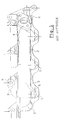
- the collector according to the invention shown in Figures 1 and 2 has a main tube 1 on which are connected four conduits 2.
- the flange 3 fixing the manifold to the cylinder head, no shown, of an internal combustion engine, comprises four clamping elements 31, made in one-piece foundry with conduits 2 and the main tube 1.
- Each clamping element comprises, in a conventional manner, a communication orifice with a respective conduit 2.
- the flange 3 is formed by cutting a thick sheet, on which the conduits 2 are then welded.
- the mounting of the manifold on the cylinder head is conventionally provided by studs and nuts, or by screws.
- the flange 3 has several holes 32 or notches 33 of semi-cylindrical shape, for the passage of the rods of said studs or screws.
- the half-cylindrical notches 33 are intended to cooperate with similar notches, performed on an intake manifold and located in correspondence during the assembly of said collectors to form cylindrical holes together. Through elsewhere, at each of these holes or notches, a counterbore 5 is produced for the service of bearing surface at the head of the screw or the nut fixation.
- a notch 37 is made in the flange at notch level 33 located in the middle of it.
- This notch formed during molding, opens on the side of the bearing face 35 of the flange and to a generally V-shaped section, as we see figure 3.
- the material section 38 remaining at this location is significantly reduced, and especially since the notch is formed just at the level of the notch in the screw passage and the counterbore corresponding.
- the weakening is thus obtained according to the invention, conducive to rupture during subsequent engine operation, as shown previously.
- the invention is not limited to the mode of realization which has just been described.
- other similar cuts could be made on the flange, at other holes or notches, or other places on the flange conducive to developing a rupture likely to reduce thermal or vibration stresses in the other parts of the collector.
- the shape and the orientation of the notch could also be modified, according to the proper forms of collectors.
Landscapes
- Engineering & Computer Science (AREA)
- Chemical & Material Sciences (AREA)
- Combustion & Propulsion (AREA)
- Mechanical Engineering (AREA)
- General Engineering & Computer Science (AREA)
- Exhaust Silencers (AREA)
Abstract
Description
- la figure 1 est une vue de face d'un collecteur selon l'art antérieur, déjà décrit au début de ce mémoire,
- la figure 2 est une vue en perspective d'un collecteur d'échappement conforme à l'invention,
- la figure 3 est une vue de dessus de ce collecteur.
Claims (7)
- Collecteur d'échappement, pour un moteur à combustion interne, comportant une bride (3) destinée à assurer la fixation du collecteur sur la culasse du moteur,
la bride présentant une continuité de matière sur sa longueur et comportant au moins une zone (38) de localisation prédéterminée qui présente un affaiblissement sensible, de valeur également prédéterminée, par rapport aux autres parties de la bride.
caractérisé en ce que la diminution de section est obtenue par une entaille transversale (37) laissant subsister une section de matière (38) offrant une résistance à la rupture à la traction comprise dans une fourchette prédéterminée. - Collecteur d'échappement selon la revendication 1, caractérisé en ce que le dit affaiblissement (38) est obtenu par une diminution localisée de la section de la bride.
- Collecteur d'échappement selon la revendication 1 ou 2, caractérisé en ce que l'entaille (37) est ménagée du côté de la face d'appui (35) du collecteur.
- Collecteur d'échappement selon la revendication 1, 2 ou 3, caractérisé en ce que l'entaille (37) a une section en « V ».
- Collecteur d'échappement selon une des revendication 1, 4 caractérisé en ce que l'affaiblissement (38) est réalisé dans une zone (33) prévue pour recevoir des moyens de fixation du collecteur sur la culasse.
- Collecteur d'échappement selon l'une des revendications 2 à 5, caractérisé en ce que la diminution de section est obtenue lors du moulage du collecteur.
- Collecteur d'échappement selon l'une des revendications 2 à 6, caractérisé en ce que la diminution de section est réalisée par un outillage adapté lors des opérations de parachèvement de la pièce après démoulage.
Applications Claiming Priority (2)
| Application Number | Priority Date | Filing Date | Title |
|---|---|---|---|
| FR0104756A FR2823255B1 (fr) | 2001-04-09 | 2001-04-09 | Collecteur d'echappement pour moteur |
| FR0104756 | 2001-04-09 |
Publications (2)
| Publication Number | Publication Date |
|---|---|
| EP1249587A1 true EP1249587A1 (fr) | 2002-10-16 |
| EP1249587B1 EP1249587B1 (fr) | 2006-03-08 |
Family
ID=8862071
Family Applications (1)
| Application Number | Title | Priority Date | Filing Date |
|---|---|---|---|
| EP20020290847 Expired - Lifetime EP1249587B1 (fr) | 2001-04-09 | 2002-04-05 | Collecteur d'échappement pour moteur |
Country Status (4)
| Country | Link |
|---|---|
| EP (1) | EP1249587B1 (fr) |
| DE (1) | DE60209667T2 (fr) |
| ES (1) | ES2254620T3 (fr) |
| FR (1) | FR2823255B1 (fr) |
Families Citing this family (2)
| Publication number | Priority date | Publication date | Assignee | Title |
|---|---|---|---|---|
| RU2246012C2 (ru) * | 2003-02-19 | 2005-02-10 | Открытое акционерное общество "Пластик" | Коллектор |
| FR2990469B1 (fr) * | 2012-05-10 | 2015-09-04 | Faurecia Sys Echappement | Raccord de collecteur d'echappement avec zone de rupture de bride |
Citations (3)
| Publication number | Priority date | Publication date | Assignee | Title |
|---|---|---|---|---|
| US4796426A (en) * | 1982-07-06 | 1989-01-10 | Feuling James J | High efficiency transition element positioned intermediate multi-cylinder exhaust system and secondary pipe assemblies |
| EP1016778A2 (fr) * | 1998-12-28 | 2000-07-05 | Hitachi Metals, Ltd. | Collecteur d'échappement monobloc avec carter de turbine pour turbocompresseur |
| US6155046A (en) * | 1998-04-20 | 2000-12-05 | Honda Giken Kogyo Kabushiki Kaisha | Heat-insulation type exhaust manifold |
-
2001
- 2001-04-09 FR FR0104756A patent/FR2823255B1/fr not_active Expired - Fee Related
-
2002
- 2002-04-05 DE DE2002609667 patent/DE60209667T2/de not_active Expired - Lifetime
- 2002-04-05 ES ES02290847T patent/ES2254620T3/es not_active Expired - Lifetime
- 2002-04-05 EP EP20020290847 patent/EP1249587B1/fr not_active Expired - Lifetime
Patent Citations (3)
| Publication number | Priority date | Publication date | Assignee | Title |
|---|---|---|---|---|
| US4796426A (en) * | 1982-07-06 | 1989-01-10 | Feuling James J | High efficiency transition element positioned intermediate multi-cylinder exhaust system and secondary pipe assemblies |
| US6155046A (en) * | 1998-04-20 | 2000-12-05 | Honda Giken Kogyo Kabushiki Kaisha | Heat-insulation type exhaust manifold |
| EP1016778A2 (fr) * | 1998-12-28 | 2000-07-05 | Hitachi Metals, Ltd. | Collecteur d'échappement monobloc avec carter de turbine pour turbocompresseur |
Also Published As
| Publication number | Publication date |
|---|---|
| DE60209667D1 (de) | 2006-05-04 |
| ES2254620T3 (es) | 2006-06-16 |
| DE60209667T2 (de) | 2006-12-14 |
| FR2823255A1 (fr) | 2002-10-11 |
| FR2823255B1 (fr) | 2003-07-04 |
| EP1249587B1 (fr) | 2006-03-08 |
Similar Documents
| Publication | Publication Date | Title |
|---|---|---|
| EP1818616A1 (fr) | Chambre de combustion de turbomachine à fentes tangentielles | |
| FR2679010A1 (fr) | Chambre de combustion de turbomachine a bols de prevaporisation demontables. | |
| FR2933887A1 (fr) | Procede de reparation ou de reprise d'un disque de turbomachine et disque de turbomachine repare ou repris | |
| FR2955364A1 (fr) | Liaison diffuseur-redresseur pour un compresseur centrifuge | |
| EP2088303B1 (fr) | Procédé de réalisation d'une plaque support pour corps de clapets et plaque support | |
| FR2618870A1 (fr) | Collier de serrage pour le raccordement de deux tubes metalliques | |
| FR2789610A1 (fr) | Procede de fabrication d'une rampe commune | |
| EP1249587B1 (fr) | Collecteur d'échappement pour moteur | |
| FR2849104A1 (fr) | Collecteur d'echappement de vehicule automobile comportant une bride de support d'un composant | |
| FR2772072A1 (fr) | Dispositif pour la fixation d'un conduit d'un premier echangeur de chaleur sur une boite a fluide d'un deuxieme echangeur de chaleur | |
| EP0391014B1 (fr) | Silencieux à absorption pour moteurs à explosion en particulier pour véhicules tout-terrain | |
| EP1930566A1 (fr) | Dispositif de fixation de deux organes mécaniques | |
| EP1780386B1 (fr) | Bride d'entrée d'un conduit coudé d'un collecteur d'échappement et moteur à combustion interne comprenant une telle bride | |
| FR2929642A1 (fr) | Tube d'alimentation en lubrifiant d'un turbocompresseur. | |
| WO1997005370A1 (fr) | Dispositif d'echappement pour moteur a combustion interne | |
| EP3158241B1 (fr) | Vanne motorisée et procédure d'assemblage d'un moyen de fixation | |
| FR2810266A1 (fr) | Manchon permettant de relier de facon etanche deux parois planes espacees paralleles en tole de relativement faible epaisseur | |
| FR2852543A1 (fr) | Procede de fixation d'une bride de raccordement sur un couvercle de collecteur d'un echangeur de chaleur | |
| FR3053756A1 (fr) | Dispositif de protection thermique pour turbocompresseur de moteur thermique | |
| WO2017089677A1 (fr) | Module de turbomachine ou de banc d'essai de chambre de combustion | |
| EP3092394B1 (fr) | Moteur borgne à combustion interne avec une etancheite aux gaz améliorée | |
| FR2925380A3 (fr) | Outil de fixation d'un filtre a particules sur une ligne d'echappement | |
| FR2916800A1 (fr) | Dispositif d'isolation d'un collecteur d'echappement | |
| FR2856737A1 (fr) | Moteur comportant un turbocompresseur monte sur un arbre de maintien au moyen d'un collier | |
| FR2927658A3 (fr) | Dispositif de traitement des gaz d'echappement a butee reglable |
Legal Events
| Date | Code | Title | Description |
|---|---|---|---|
| PUAI | Public reference made under article 153(3) epc to a published international application that has entered the european phase |
Free format text: ORIGINAL CODE: 0009012 |
|
| AK | Designated contracting states |
Kind code of ref document: A1 Designated state(s): AT BE CH CY DE DK ES FI FR GB GR IE IT LI LU MC NL PT SE TR |
|
| AX | Request for extension of the european patent |
Free format text: AL;LT;LV;MK;RO;SI |
|
| 17P | Request for examination filed |
Effective date: 20030403 |
|
| AKX | Designation fees paid |
Designated state(s): DE ES GB IT |
|
| GRAP | Despatch of communication of intention to grant a patent |
Free format text: ORIGINAL CODE: EPIDOSNIGR1 |
|
| GRAS | Grant fee paid |
Free format text: ORIGINAL CODE: EPIDOSNIGR3 |
|
| GRAA | (expected) grant |
Free format text: ORIGINAL CODE: 0009210 |
|
| AK | Designated contracting states |
Kind code of ref document: B1 Designated state(s): DE ES GB IT |
|
| REG | Reference to a national code |
Ref country code: GB Ref legal event code: FG4D Free format text: NOT ENGLISH |
|
| GBT | Gb: translation of ep patent filed (gb section 77(6)(a)/1977) |
Effective date: 20060327 |
|
| REF | Corresponds to: |
Ref document number: 60209667 Country of ref document: DE Date of ref document: 20060504 Kind code of ref document: P |
|
| REG | Reference to a national code |
Ref country code: ES Ref legal event code: FG2A Ref document number: 2254620 Country of ref document: ES Kind code of ref document: T3 |
|
| PLBE | No opposition filed within time limit |
Free format text: ORIGINAL CODE: 0009261 |
|
| STAA | Information on the status of an ep patent application or granted ep patent |
Free format text: STATUS: NO OPPOSITION FILED WITHIN TIME LIMIT |
|
| 26N | No opposition filed |
Effective date: 20061211 |
|
| PGFP | Annual fee paid to national office [announced via postgrant information from national office to epo] |
Ref country code: ES Payment date: 20160413 Year of fee payment: 15 Ref country code: GB Payment date: 20160421 Year of fee payment: 15 Ref country code: DE Payment date: 20160421 Year of fee payment: 15 |
|
| PGFP | Annual fee paid to national office [announced via postgrant information from national office to epo] |
Ref country code: IT Payment date: 20160427 Year of fee payment: 15 |
|
| REG | Reference to a national code |
Ref country code: DE Ref legal event code: R119 Ref document number: 60209667 Country of ref document: DE |
|
| GBPC | Gb: european patent ceased through non-payment of renewal fee |
Effective date: 20170405 |
|
| PG25 | Lapsed in a contracting state [announced via postgrant information from national office to epo] |
Ref country code: DE Free format text: LAPSE BECAUSE OF NON-PAYMENT OF DUE FEES Effective date: 20171103 |
|
| PG25 | Lapsed in a contracting state [announced via postgrant information from national office to epo] |
Ref country code: GB Free format text: LAPSE BECAUSE OF NON-PAYMENT OF DUE FEES Effective date: 20170405 |
|
| PG25 | Lapsed in a contracting state [announced via postgrant information from national office to epo] |
Ref country code: IT Free format text: LAPSE BECAUSE OF NON-PAYMENT OF DUE FEES Effective date: 20170405 |
|
| REG | Reference to a national code |
Ref country code: ES Ref legal event code: FD2A Effective date: 20180628 |
|
| PG25 | Lapsed in a contracting state [announced via postgrant information from national office to epo] |
Ref country code: ES Free format text: LAPSE BECAUSE OF NON-PAYMENT OF DUE FEES Effective date: 20170406 |