EP1249191A2 - Securing mechanism for closing drawers - Google Patents
Securing mechanism for closing drawers Download PDFInfo
- Publication number
- EP1249191A2 EP1249191A2 EP02380071A EP02380071A EP1249191A2 EP 1249191 A2 EP1249191 A2 EP 1249191A2 EP 02380071 A EP02380071 A EP 02380071A EP 02380071 A EP02380071 A EP 02380071A EP 1249191 A2 EP1249191 A2 EP 1249191A2
- Authority
- EP
- European Patent Office
- Prior art keywords
- drawer
- projection
- latch
- spring
- chassis
- Prior art date
- Legal status (The legal status is an assumption and is not a legal conclusion. Google has not performed a legal analysis and makes no representation as to the accuracy of the status listed.)
- Withdrawn
Links
Images


Classifications
-
- A—HUMAN NECESSITIES
- A47—FURNITURE; DOMESTIC ARTICLES OR APPLIANCES; COFFEE MILLS; SPICE MILLS; SUCTION CLEANERS IN GENERAL
- A47B—TABLES; DESKS; OFFICE FURNITURE; CABINETS; DRAWERS; GENERAL DETAILS OF FURNITURE
- A47B88/00—Drawers for tables, cabinets or like furniture; Guides for drawers
- A47B88/40—Sliding drawers; Slides or guides therefor
- A47B88/453—Actuated drawers
- A47B88/46—Actuated drawers operated by mechanically-stored energy, e.g. by springs
- A47B88/467—Actuated drawers operated by mechanically-stored energy, e.g. by springs self-closing
Definitions
- the present invention relates to a securing mechanism for closing drawers of those that are incorporated in the guides of the drawer in order to exercise a pushing action on the drawer to complete the closure.
- This mechanism is characterised in the presence of a casing with a means of guidance and support that contains a spring working in tension for retracting a mobile piece with a double-action latch.
- Means for the retraction of drawers exist that are based on guides that increase the gradient in their end section so that the closing of the drawer is assured by gravity.
- the Spanish Patent with publication number ES2139476 is known wherein a mechanism is described based on a double rocking latch that though it carries out the same function, has a limitation in the interval of action resulting from the radius of rotation of the latch whose dimensions are limited by the height of the drawer guide.
- the present invention consists of a securing mechanism for closing that incorporates a smaller number of piece parts and offers a much greater interval of retention than the known systems.
- the invention proposed herein consists of a mechanism intended to assure the closing of drawers by means of a double-acting latch that rests on a small plate starting from a point near to the closed position and exercises a force that retracts the drawer into its final position.
- This mechanism consists of a chassis formed basically by a rectangular small plate with peripheral projections so that when resting on the internal surface of the drawer guide on which it is installed, a housing is defined in which its components are lodged and where the projections are the side walls of this chassis.
- This mechanism presents two symmetrical constructions, one for the right-hand drawer guide and another for the left-hand guide both constructions being the same invention.
- the chassis has three points of fastening on the drawer guide, an upper one for anchoring in a hooked projection constituted on the drawer guide, and two ends that are secured in slots also present in the guide, one fixed and another on a flexible small plate to be fixed by clip-fitting.
- the spring is fastened at one end on a projection and housed in a semi-cylindrical recess of length somewhat greater than the dimension it reaches when extended to the maximum.
- the spring is anchored to an upper projection of the latch exercising in any of its positions a pulling force.
- This double-acting latch is a mainly flat body, with a transversal pivot that penetrates a guiding slot parallel to the semi-cylindrical recess.
- a lower thickening that covers almost the whole of the latch allows the latter to abut upon the flat surface of the chassis on one side and on the flat surface of the chassis on the other side which together with the guiding slot constitute the means of support and guidance.
- This guiding slot restricts the movement of the latch to two degrees of freedom, one associated with the movement of rectilinear displacement parallel to the longitudinal axis of the chassis, and another of rotation about the pivot.
- the tension spring locates its support above the transversal axis defined by the pivot so that the pull establishes a turning couple that is impeded by an upper projection that abuts upon the upper wall of the chassis.
- the lower part of the latch presents a horizontal flat surface, under which is lodged the small plate joined to the drawer, flanked by projections that are those which allow the double action of the latch on this small plate.
- the projection opposite the spring is that which exercises the tensioning support to assure the closing of the drawer, and also, when the drawer is closed, is pulled upon to achieve the opening.
- This configuration is outstanding in the amplitude of the interval over which the push on the drawer is established.
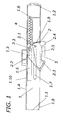
- Figure 1 shows the mechanism in elevation when the drawer is closed and likewise shows a cross-section of the small plate joined to the drawer secured by the latch.
- Figure 2 shows the same elevation with the spring extended after having opened the drawer.
- Figure 3 is an elevation and plan view of the latch.
- the present invention relates to a mechanism for securing the closure of drawers.
- Figure 1 represents an elevation of an embodiment of the mechanism.
- This mechanism is formed by a chassis (1) that consists mainly of a small plate and projections that cover the sides, closing the guide assembly of the drawer that is not shown for access to the interior of the mechanism.
- the means of fastening the chassis (1) to the drawer guide are three, an upper one (1.3) that houses a hooked projection of the drawer guide and two lateral ones (1.1, 1.2) with side projections at the ends that are lodged in slots also present in the drawer guide, one (1.1) of them being configured in a flexible small plate to allow clip-fitting.
- a projection (1.6) that allows the fastening of an end of a spring (4) that works in tension.
- This spring (4) is lodged in a semi-cylindrical recess (1.5) that covers a great part of the length of the chassis (1) to allow its extension.
- the other end of the spring (4) is secured to a projection (2.3) of the latch (2) that is shown in form of an opposing hook.
- this projection (2.3) has, to prevent the spring (4) from escaping, a small projection (2.3.2) facing another (2.3.1) both of smaller width.
- This latch has a pivot (2.1) that is lodged in a slot (1.7) that serves as guide and that allows a longitudinal displacement parallel to the displacement of the drawer.
- the pull of the spring (4) produces a turning couple that is impeded by the support of an upper projection (2.2) on the upper wall (1.10) during the full travel except when the spring (4) is completely extended, since it is opposite a hole (1.4) in which it is lodged, restraining the pull of the spring (4) and impeding thereby that the latch (2) retracts.
- the latch (2) presents on the underside a horizontal surface (2.5) parallel to the small plate (3) joined to the drawer and on both sides of said surface (2.5) opposing projections (2.3) and (2.4) that allow the double action of the latch (2).
- the latch (2) is flanked by two flat surfaces that guide it, one that of the chassis (1) and the other that of the drawer guide upon which it abuts by means of a thickening (2.6) that occupies great part of its area.
- the travel of the latch (2) is likewise limited by a lower projection (1.8) present on the chassis (1).
- the other lower projection (2.4) remains standing out waiting for the drawer to be closed and the small plate (3) to come up against it so that it releases the upper projection (2.2) and the lower projection (2.3) abutting in turn that had been retracted.
- the spring (4) will restore the drawer to its complete closure, the latch being on this side limited in its displacement by a support (1.9) prolongation of the side face toward the interior.
Abstract
Description
- The present invention relates to a securing mechanism for closing drawers of those that are incorporated in the guides of the drawer in order to exercise a pushing action on the drawer to complete the closure.
- This mechanism is characterised in the presence of a casing with a means of guidance and support that contains a spring working in tension for retracting a mobile piece with a double-action latch.
- It is characterised in the presence of a slot that allows the longitudinal displacement of the latch by means of a pivot and the support of an upper projection until the end of travel is reached, in the position of maximum opening, where such support is no longer present, rotation of the latch taking place to release the small plate joined to the drawer.
- It is characterised in an ample scope of action of the assembly formed by the latch and the spring on the small plate for the retraction of the drawer.
- Means for the retraction of drawers exist that are based on guides that increase the gradient in their end section so that the closing of the drawer is assured by gravity.
- The Spanish Patent with publication number ES2139476 is known wherein a mechanism is described based on a double rocking latch that though it carries out the same function, has a limitation in the interval of action resulting from the radius of rotation of the latch whose dimensions are limited by the height of the drawer guide.
- The present invention consists of a securing mechanism for closing that incorporates a smaller number of piece parts and offers a much greater interval of retention than the known systems.
- The invention proposed herein consists of a mechanism intended to assure the closing of drawers by means of a double-acting latch that rests on a small plate starting from a point near to the closed position and exercises a force that retracts the drawer into its final position.
- This mechanism consists of a chassis formed basically by a rectangular small plate with peripheral projections so that when resting on the internal surface of the drawer guide on which it is installed, a housing is defined in which its components are lodged and where the projections are the side walls of this chassis.
- This mechanism presents two symmetrical constructions, one for the right-hand drawer guide and another for the left-hand guide both constructions being the same invention.
- The chassis has three points of fastening on the drawer guide, an upper one for anchoring in a hooked projection constituted on the drawer guide, and two ends that are secured in slots also present in the guide, one fixed and another on a flexible small plate to be fixed by clip-fitting.
- On the inside of this chassis only two pieces are located, a spring that only works in tension and a double-acting latch.
- The spring is fastened at one end on a projection and housed in a semi-cylindrical recess of length somewhat greater than the dimension it reaches when extended to the maximum.
- At the other end, the spring is anchored to an upper projection of the latch exercising in any of its positions a pulling force.
- This double-acting latch is a mainly flat body, with a transversal pivot that penetrates a guiding slot parallel to the semi-cylindrical recess.
- A lower thickening that covers almost the whole of the latch allows the latter to abut upon the flat surface of the chassis on one side and on the flat surface of the chassis on the other side which together with the guiding slot constitute the means of support and guidance.
- This guiding slot restricts the movement of the latch to two degrees of freedom, one associated with the movement of rectilinear displacement parallel to the longitudinal axis of the chassis, and another of rotation about the pivot.
- The tension spring locates its support above the transversal axis defined by the pivot so that the pull establishes a turning couple that is impeded by an upper projection that abuts upon the upper wall of the chassis.
- In this position, the lower part of the latch presents a horizontal flat surface, under which is lodged the small plate joined to the drawer, flanked by projections that are those which allow the double action of the latch on this small plate.
- The projection opposite the spring is that which exercises the tensioning support to assure the closing of the drawer, and also, when the drawer is closed, is pulled upon to achieve the opening.
- When the drawer is pulled and the tension in the spring is overcome, the latch is displaced to the end of the run defined by the guiding slot.
- At this moment, the upper projection that impedes its rotation is opposite a hole ceasing to abut upon the upper wall, the moment at which the latch rotates sufficiently for the lower support opposite the spring to cease acting.
- In this situation, the drawer is released in order to complete its opening travel and the latch is secured by the upper projection that has penetrated the upper hole in opposition to the spring that has been extended to the maximum.
- When the drawer is closed again, in its displacement the small plate will come to abut upon the lower projection, this time that on the side of the spring, so that it forces the rotation of the latch until the upper spring is released.
- Once the upper spring has been released, and therefore the lower spring abuts again upon the small plate joined to the drawer, the pull of the spring is communicated to the drawer in order to have this impel it to total closure of the drawer.
- This configuration is outstanding in the amplitude of the interval over which the push on the drawer is established.
- The present specification is completed, with a set of drawings which illustrates the preferred embodiment of the invention and which must not be interpreted restrictively.
- Figure 1 shows the mechanism in elevation when the drawer is closed and likewise shows a cross-section of the small plate joined to the drawer secured by the latch.
- Figure 2 shows the same elevation with the spring extended after having opened the drawer.
- Figure 3 is an elevation and plan view of the latch.
- In the light of the foregoing, the present invention relates to a mechanism for securing the closure of drawers.
- Figure 1 represents an elevation of an embodiment of the mechanism.
- This mechanism is formed by a chassis (1) that consists mainly of a small plate and projections that cover the sides, closing the guide assembly of the drawer that is not shown for access to the interior of the mechanism.
- The means of fastening the chassis (1) to the drawer guide are three, an upper one (1.3) that houses a hooked projection of the drawer guide and two lateral ones (1.1, 1.2) with side projections at the ends that are lodged in slots also present in the drawer guide, one (1.1) of them being configured in a flexible small plate to allow clip-fitting.
- On the end of the chassis (1) that is positioned on the side of the back of the drawer is a projection (1.6) that allows the fastening of an end of a spring (4) that works in tension.
- This spring (4) is lodged in a semi-cylindrical recess (1.5) that covers a great part of the length of the chassis (1) to allow its extension.
- The other end of the spring (4) is secured to a projection (2.3) of the latch (2) that is shown in form of an opposing hook.
- In turn this projection (2.3) has, to prevent the spring (4) from escaping, a small projection (2.3.2) facing another (2.3.1) both of smaller width.
- This latch has a pivot (2.1) that is lodged in a slot (1.7) that serves as guide and that allows a longitudinal displacement parallel to the displacement of the drawer.
- The pull of the spring (4) produces a turning couple that is impeded by the support of an upper projection (2.2) on the upper wall (1.10) during the full travel except when the spring (4) is completely extended, since it is opposite a hole (1.4) in which it is lodged, restraining the pull of the spring (4) and impeding thereby that the latch (2) retracts.
- During the full travel, the latch (2) presents on the underside a horizontal surface (2.5) parallel to the small plate (3) joined to the drawer and on both sides of said surface (2.5) opposing projections (2.3) and (2.4) that allow the double action of the latch (2).
- Over all its travel, the latch (2) is flanked by two flat surfaces that guide it, one that of the chassis (1) and the other that of the drawer guide upon which it abuts by means of a thickening (2.6) that occupies great part of its area.
- Just as is shown in figure 2, once the mechanism is fully extended and therefore the upper projection (2.2) has been lodged in the hole (1.4), the latch (2) has rotated assisted by the couple applied by the spring (4) so that the projection (2.3) releases the lower small plate.
- The travel of the latch (2) is likewise limited by a lower projection (1.8) present on the chassis (1).
- The other lower projection (2.4) remains standing out waiting for the drawer to be closed and the small plate (3) to come up against it so that it releases the upper projection (2.2) and the lower projection (2.3) abutting in turn that had been retracted.
- Thus, the spring (4) will restore the drawer to its complete closure, the latch being on this side limited in its displacement by a support (1.9) prolongation of the side face toward the interior.
- The essential nature of this invention is not altered by variation in materials, form, size and arrangement of the component elements, described in a non-restrictive manner that is sufficient for an expert to proceed to its reproduction.
Claims (1)
- Securing mechanism for closing drawers, from among the means intended to favour the total retraction of the drawers and that are installed on the guide on which the drawers run essentially characterised in that it is formed by a chassis (1) with means of securing both on its upper part (1.3) and on its ends (1.1), and (1.2), these last ones being based on clip-fitting; housing on its inside a spring (4) lodged in a longitudinal semi-cylindrical recess (1.5), this spring (4) being fastened at the end oriented toward the back of the drawer to a projection (1.6) joined to the chassis (1), and the other end to a projection (2.3) of a double-acting latch (2) that presents some means of guidance consisting of a flat thickening (2.6), covering almost the whole area, of support between the surface of the chassis (1) and of the drawer guide, as well as of a transversal pivot (2.1) that lodges in a slot (1.7) for longitudinal guidance, this latch (2) being capable of linear displacement along the guiding slot (1.7) and of rotation at the end of its travel; it has two lower projections (2.3) and (2.4) that delimit the small plate (3) joined to the drawer, except in the extended position where the projection (2.3) opposing the spring (4) is withdrawn and the small plate (3) is released, since it has a third upper projection (2.2) for impeding the rotation of the latch (2) along the travel by abutting upon the upper face (1.10) except in its position of maximum extension through the presence of a hole (1.4) capable of housing said projection (2.2).
Applications Claiming Priority (2)
| Application Number | Priority Date | Filing Date | Title |
|---|---|---|---|
| ES200100932U | 2001-04-11 | ||
| ES200100932U ES1048667Y (en) | 2001-04-11 | 2001-04-11 | SECURITY MECHANISM FOR CLOSURE OF DRAWERS |
Publications (2)
| Publication Number | Publication Date |
|---|---|
| EP1249191A2 true EP1249191A2 (en) | 2002-10-16 |
| EP1249191A3 EP1249191A3 (en) | 2004-01-02 |
Family
ID=8497505
Family Applications (1)
| Application Number | Title | Priority Date | Filing Date |
|---|---|---|---|
| EP02380071A Withdrawn EP1249191A3 (en) | 2001-04-11 | 2002-04-01 | Securing mechanism for closing drawers |
Country Status (2)
| Country | Link |
|---|---|
| EP (1) | EP1249191A3 (en) |
| ES (1) | ES1048667Y (en) |
Cited By (3)
| Publication number | Priority date | Publication date | Assignee | Title |
|---|---|---|---|---|
| EP1491676A2 (en) | 2003-06-28 | 2004-12-29 | LG Electronics Inc. | Stand for home appliance |
| WO2006058351A1 (en) * | 2004-12-03 | 2006-06-08 | Julius Blum Gmbh | Drive device for a displaceably mounted furniture part |
| US20180209659A1 (en) * | 2017-01-26 | 2018-07-26 | Samsung Electronics Co., Ltd | Cooking apparatus |
Citations (1)
| Publication number | Priority date | Publication date | Assignee | Title |
|---|---|---|---|---|
| ES2139476A1 (en) | 1995-02-02 | 2000-02-01 | Ind Ragi S A | Drawer closure safety device |
Family Cites Families (3)
| Publication number | Priority date | Publication date | Assignee | Title |
|---|---|---|---|---|
| AT400219B (en) * | 1991-12-24 | 1995-11-27 | Blum Gmbh Julius | LOCKING DEVICE FOR DRAWERS |
| AT407602B (en) * | 1994-08-31 | 2001-05-25 | Alfit Ag | PULL-IN DEVICE FOR DRAWERS |
| DE9420920U1 (en) * | 1994-12-30 | 1995-02-09 | Klaus Brummernhenrich Kunststo | Drawer pull-in fitting |
-
2001
- 2001-04-11 ES ES200100932U patent/ES1048667Y/en not_active Expired - Fee Related
-
2002
- 2002-04-01 EP EP02380071A patent/EP1249191A3/en not_active Withdrawn
Patent Citations (1)
| Publication number | Priority date | Publication date | Assignee | Title |
|---|---|---|---|---|
| ES2139476A1 (en) | 1995-02-02 | 2000-02-01 | Ind Ragi S A | Drawer closure safety device |
Cited By (7)
| Publication number | Priority date | Publication date | Assignee | Title |
|---|---|---|---|---|
| EP1491676A2 (en) | 2003-06-28 | 2004-12-29 | LG Electronics Inc. | Stand for home appliance |
| WO2006058351A1 (en) * | 2004-12-03 | 2006-06-08 | Julius Blum Gmbh | Drive device for a displaceably mounted furniture part |
| JP2008521517A (en) * | 2004-12-03 | 2008-06-26 | ジュリウス ブルム ゲゼルシャフト エム.ビー.エイチ. | Actuator for furniture parts mounted so as to be displaceable |
| US7748799B2 (en) | 2004-12-03 | 2010-07-06 | Julius Blum Gmbh | Drive device for a movably mounted furniture part |
| CN101068487B (en) * | 2004-12-03 | 2011-04-13 | 尤利乌斯·布卢姆有限公司 | Driving device for drawer capable of being movably installed |
| US20180209659A1 (en) * | 2017-01-26 | 2018-07-26 | Samsung Electronics Co., Ltd | Cooking apparatus |
| US10746411B2 (en) * | 2017-01-26 | 2020-08-18 | Samsung Electronics Co., Ltd. | Cooking apparatus |
Also Published As
| Publication number | Publication date |
|---|---|
| ES1048667Y (en) | 2002-02-01 |
| ES1048667U (en) | 2001-09-01 |
| EP1249191A3 (en) | 2004-01-02 |
Similar Documents
| Publication | Publication Date | Title |
|---|---|---|
| US5302016A (en) | Automatic pull-in mechanism for drawer guides | |
| KR101223810B1 (en) | Self closing mechanism for drawer slides | |
| US6666306B2 (en) | Damping device for movable furniture parts | |
| ES2233908T3 (en) | SLIDING MECHANISM. | |
| KR100573084B1 (en) | Self closing means for a slide | |
| US9648952B2 (en) | Pressure release slide latch mechanism | |
| ES2248188T3 (en) | CLOSURE DEACELERATION DEVICE FOR SLIDING PORTS OF FURNITURE PARTS. | |
| US5630248A (en) | Door closer with semi-automatic latching | |
| KR101143569B1 (en) | Adjusting device for auto-closed | |
| KR100988389B1 (en) | Slider for double-sided slide fastener with automatic locking device | |
| KR20000057405A (en) | Easy-to-use roller blind | |
| US10512328B2 (en) | Retraction device and pull-out guide | |
| KR100537017B1 (en) | Slide with self closing means | |
| PL223707B1 (en) | Close unit for sliding doors | |
| JPH0432971Y2 (en) | ||
| JP2007308888A (en) | Shock absorbing device of hinged door | |
| EP1249191A2 (en) | Securing mechanism for closing drawers | |
| US20130287324A1 (en) | Pressure Release Slide Latch Mechanism | |
| KR100407480B1 (en) | Opening and shutting device using safe door | |
| KR20100071366A (en) | Sliding door system | |
| KR200483169Y1 (en) | Door lock for a cowhouse | |
| JPH1029783A (en) | Sill device for elevator | |
| JP2010070990A (en) | Support fixing implement with lock mechanism | |
| JPH1029784A (en) | Sill device for elevator | |
| JP2008100012A (en) | Slide rail |
Legal Events
| Date | Code | Title | Description |
|---|---|---|---|
| PUAI | Public reference made under article 153(3) epc to a published international application that has entered the european phase |
Free format text: ORIGINAL CODE: 0009012 |
|
| AK | Designated contracting states |
Kind code of ref document: A2 Designated state(s): AT BE CH CY DE DK ES FI FR GB GR IE IT LI LU MC NL PT SE TR |
|
| AX | Request for extension of the european patent |
Free format text: AL;LT;LV;MK;RO;SI |
|
| PUAL | Search report despatched |
Free format text: ORIGINAL CODE: 0009013 |
|
| AK | Designated contracting states |
Kind code of ref document: A3 Designated state(s): AT BE CH CY DE DK ES FI FR GB GR IE IT LI LU MC NL PT SE TR |
|
| AX | Request for extension of the european patent |
Extension state: AL LT LV MK RO SI |
|
| STAA | Information on the status of an ep patent application or granted ep patent |
Free format text: STATUS: THE APPLICATION HAS BEEN WITHDRAWN |
|
| 18W | Application withdrawn |
Effective date: 20040212 |