EP1248902B1 - Raketendüse mit hochtemperaturfestem schutzschild - Google Patents
Raketendüse mit hochtemperaturfestem schutzschild Download PDFInfo
- Publication number
- EP1248902B1 EP1248902B1 EP01926336A EP01926336A EP1248902B1 EP 1248902 B1 EP1248902 B1 EP 1248902B1 EP 01926336 A EP01926336 A EP 01926336A EP 01926336 A EP01926336 A EP 01926336A EP 1248902 B1 EP1248902 B1 EP 1248902B1
- Authority
- EP
- European Patent Office
- Prior art keywords
- throat
- shell
- surface region
- rocket motor
- refractory metal
- Prior art date
- Legal status (The legal status is an assumption and is not a legal conclusion. Google has not performed a legal analysis and makes no representation as to the accuracy of the status listed.)
- Expired - Lifetime
Links
- 239000003870 refractory metal Substances 0.000 title claims description 48
- 238000002485 combustion reaction Methods 0.000 claims description 53
- VYPSYNLAJGMNEJ-UHFFFAOYSA-N Silicium dioxide Chemical compound O=[Si]=O VYPSYNLAJGMNEJ-UHFFFAOYSA-N 0.000 claims description 46
- 239000000463 material Substances 0.000 claims description 40
- 230000037361 pathway Effects 0.000 claims description 37
- 230000001681 protective effect Effects 0.000 claims description 36
- 238000000034 method Methods 0.000 claims description 29
- 210000000744 eyelid Anatomy 0.000 claims description 27
- 239000000377 silicon dioxide Substances 0.000 claims description 23
- 239000003380 propellant Substances 0.000 claims description 18
- 229910001092 metal group alloy Inorganic materials 0.000 claims description 17
- 239000003575 carbonaceous material Substances 0.000 claims description 15
- WFKWXMTUELFFGS-UHFFFAOYSA-N tungsten Chemical compound [W] WFKWXMTUELFFGS-UHFFFAOYSA-N 0.000 claims description 12
- 239000010937 tungsten Substances 0.000 claims description 12
- 229910045601 alloy Inorganic materials 0.000 claims description 10
- 239000000956 alloy Substances 0.000 claims description 10
- 229910052721 tungsten Inorganic materials 0.000 claims description 9
- 238000002844 melting Methods 0.000 claims description 6
- 230000008018 melting Effects 0.000 claims description 6
- 229910052702 rhenium Inorganic materials 0.000 claims description 6
- WUAPFZMCVAUBPE-UHFFFAOYSA-N rhenium atom Chemical compound [Re] WUAPFZMCVAUBPE-UHFFFAOYSA-N 0.000 claims description 6
- 238000010290 vacuum plasma spraying Methods 0.000 claims description 5
- 238000004519 manufacturing process Methods 0.000 claims description 4
- 229910052715 tantalum Inorganic materials 0.000 claims description 4
- GUVRBAGPIYLISA-UHFFFAOYSA-N tantalum atom Chemical compound [Ta] GUVRBAGPIYLISA-UHFFFAOYSA-N 0.000 claims description 4
- 238000007750 plasma spraying Methods 0.000 claims description 3
- 229910000691 Re alloy Inorganic materials 0.000 claims 3
- 229910001080 W alloy Inorganic materials 0.000 claims 3
- UQMRAFJOBWOFNS-UHFFFAOYSA-N butyl 2-(2,4-dichlorophenoxy)acetate Chemical compound CCCCOC(=O)COC1=CC=C(Cl)C=C1Cl UQMRAFJOBWOFNS-UHFFFAOYSA-N 0.000 description 33
- OKTJSMMVPCPJKN-UHFFFAOYSA-N Carbon Chemical compound [C] OKTJSMMVPCPJKN-UHFFFAOYSA-N 0.000 description 29
- 229910052799 carbon Inorganic materials 0.000 description 20
- 239000007789 gas Substances 0.000 description 13
- 230000003628 erosive effect Effects 0.000 description 12
- 239000004744 fabric Substances 0.000 description 11
- 238000001723 curing Methods 0.000 description 10
- 239000002131 composite material Substances 0.000 description 9
- 239000000945 filler Substances 0.000 description 9
- 238000009413 insulation Methods 0.000 description 9
- 239000000835 fiber Substances 0.000 description 8
- 229910002804 graphite Inorganic materials 0.000 description 8
- 239000010439 graphite Substances 0.000 description 8
- 229920001568 phenolic resin Polymers 0.000 description 8
- 239000005011 phenolic resin Substances 0.000 description 8
- 229920005989 resin Polymers 0.000 description 7
- 239000011347 resin Substances 0.000 description 7
- KXGFMDJXCMQABM-UHFFFAOYSA-N 2-methoxy-6-methylphenol Chemical compound [CH]OC1=CC=CC([CH])=C1O KXGFMDJXCMQABM-UHFFFAOYSA-N 0.000 description 6
- 239000000567 combustion gas Substances 0.000 description 6
- 239000011819 refractory material Substances 0.000 description 6
- 229920002239 polyacrylonitrile Polymers 0.000 description 5
- 239000004449 solid propellant Substances 0.000 description 5
- XKRFYHLGVUSROY-UHFFFAOYSA-N Argon Chemical compound [Ar] XKRFYHLGVUSROY-UHFFFAOYSA-N 0.000 description 4
- 229920000297 Rayon Polymers 0.000 description 4
- 230000008901 benefit Effects 0.000 description 4
- 229910052751 metal Inorganic materials 0.000 description 4
- 239000002184 metal Substances 0.000 description 4
- 235000013824 polyphenols Nutrition 0.000 description 4
- 230000008569 process Effects 0.000 description 4
- 239000002964 rayon Substances 0.000 description 4
- 230000008646 thermal stress Effects 0.000 description 4
- 229920003235 aromatic polyamide Polymers 0.000 description 3
- 238000006243 chemical reaction Methods 0.000 description 3
- 238000010438 heat treatment Methods 0.000 description 3
- 239000007788 liquid Substances 0.000 description 3
- 239000007800 oxidant agent Substances 0.000 description 3
- 239000002245 particle Substances 0.000 description 3
- 229920000728 polyester Polymers 0.000 description 3
- -1 polyethylene Polymers 0.000 description 3
- 239000000843 powder Substances 0.000 description 3
- 230000002787 reinforcement Effects 0.000 description 3
- CURLTUGMZLYLDI-UHFFFAOYSA-N Carbon dioxide Chemical compound O=C=O CURLTUGMZLYLDI-UHFFFAOYSA-N 0.000 description 2
- 239000004677 Nylon Substances 0.000 description 2
- 229910052786 argon Inorganic materials 0.000 description 2
- IISBACLAFKSPIT-UHFFFAOYSA-N bisphenol A Chemical compound C=1C=C(O)C=CC=1C(C)(C)C1=CC=C(O)C=C1 IISBACLAFKSPIT-UHFFFAOYSA-N 0.000 description 2
- 238000005056 compaction Methods 0.000 description 2
- 238000001816 cooling Methods 0.000 description 2
- 230000001351 cycling effect Effects 0.000 description 2
- 230000001419 dependent effect Effects 0.000 description 2
- 238000013461 design Methods 0.000 description 2
- 238000010891 electric arc Methods 0.000 description 2
- 238000010304 firing Methods 0.000 description 2
- 239000000446 fuel Substances 0.000 description 2
- 239000003365 glass fiber Substances 0.000 description 2
- 230000014759 maintenance of location Effects 0.000 description 2
- 238000012986 modification Methods 0.000 description 2
- 230000004048 modification Effects 0.000 description 2
- 229920001778 nylon Polymers 0.000 description 2
- 229910010271 silicon carbide Inorganic materials 0.000 description 2
- 239000007787 solid Substances 0.000 description 2
- 238000005507 spraying Methods 0.000 description 2
- 238000005382 thermal cycling Methods 0.000 description 2
- 238000005979 thermal decomposition reaction Methods 0.000 description 2
- 229920001187 thermosetting polymer Polymers 0.000 description 2
- XQUPVDVFXZDTLT-UHFFFAOYSA-N 1-[4-[[4-(2,5-dioxopyrrol-1-yl)phenyl]methyl]phenyl]pyrrole-2,5-dione Chemical compound O=C1C=CC(=O)N1C(C=C1)=CC=C1CC1=CC=C(N2C(C=CC2=O)=O)C=C1 XQUPVDVFXZDTLT-UHFFFAOYSA-N 0.000 description 1
- 229910052582 BN Inorganic materials 0.000 description 1
- ZOXJGFHDIHLPTG-UHFFFAOYSA-N Boron Chemical compound [B] ZOXJGFHDIHLPTG-UHFFFAOYSA-N 0.000 description 1
- PZNSFCLAULLKQX-UHFFFAOYSA-N Boron nitride Chemical compound N#B PZNSFCLAULLKQX-UHFFFAOYSA-N 0.000 description 1
- 229920000049 Carbon (fiber) Polymers 0.000 description 1
- 229920000742 Cotton Polymers 0.000 description 1
- 239000004593 Epoxy Substances 0.000 description 1
- UFHFLCQGNIYNRP-UHFFFAOYSA-N Hydrogen Chemical compound [H][H] UFHFLCQGNIYNRP-UHFFFAOYSA-N 0.000 description 1
- 229920000271 Kevlar® Polymers 0.000 description 1
- 239000004698 Polyethylene Substances 0.000 description 1
- 239000000853 adhesive Substances 0.000 description 1
- 230000001070 adhesive effect Effects 0.000 description 1
- 230000002411 adverse Effects 0.000 description 1
- PNEYBMLMFCGWSK-UHFFFAOYSA-N aluminium oxide Inorganic materials [O-2].[O-2].[O-2].[Al+3].[Al+3] PNEYBMLMFCGWSK-UHFFFAOYSA-N 0.000 description 1
- 229910000410 antimony oxide Inorganic materials 0.000 description 1
- 239000004760 aramid Substances 0.000 description 1
- 229940054066 benzamide antipsychotics Drugs 0.000 description 1
- 150000003936 benzamides Chemical class 0.000 description 1
- 239000011230 binding agent Substances 0.000 description 1
- 230000015572 biosynthetic process Effects 0.000 description 1
- 229910052796 boron Inorganic materials 0.000 description 1
- CREMABGTGYGIQB-UHFFFAOYSA-N carbon carbon Chemical compound C.C CREMABGTGYGIQB-UHFFFAOYSA-N 0.000 description 1
- 229910002092 carbon dioxide Inorganic materials 0.000 description 1
- 239000001569 carbon dioxide Substances 0.000 description 1
- 239000004917 carbon fiber Substances 0.000 description 1
- 239000011203 carbon fibre reinforced carbon Substances 0.000 description 1
- 238000003763 carbonization Methods 0.000 description 1
- 238000005266 casting Methods 0.000 description 1
- 238000004891 communication Methods 0.000 description 1
- 239000000470 constituent Substances 0.000 description 1
- 238000007796 conventional method Methods 0.000 description 1
- 239000002826 coolant Substances 0.000 description 1
- 238000000354 decomposition reaction Methods 0.000 description 1
- 230000003247 decreasing effect Effects 0.000 description 1
- GYZLOYUZLJXAJU-UHFFFAOYSA-N diglycidyl ether Chemical class C1OC1COCC1CO1 GYZLOYUZLJXAJU-UHFFFAOYSA-N 0.000 description 1
- 229920001971 elastomer Polymers 0.000 description 1
- 239000000806 elastomer Substances 0.000 description 1
- 229920006332 epoxy adhesive Polymers 0.000 description 1
- 239000003822 epoxy resin Substances 0.000 description 1
- 239000012530 fluid Substances 0.000 description 1
- 239000011521 glass Substances 0.000 description 1
- 238000005087 graphitization Methods 0.000 description 1
- 230000005484 gravity Effects 0.000 description 1
- LNEPOXFFQSENCJ-UHFFFAOYSA-N haloperidol Chemical compound C1CC(O)(C=2C=CC(Cl)=CC=2)CCN1CCCC(=O)C1=CC=C(F)C=C1 LNEPOXFFQSENCJ-UHFFFAOYSA-N 0.000 description 1
- 239000001257 hydrogen Substances 0.000 description 1
- 229910052739 hydrogen Inorganic materials 0.000 description 1
- 239000012774 insulation material Substances 0.000 description 1
- 239000004761 kevlar Substances 0.000 description 1
- 238000011068 loading method Methods 0.000 description 1
- 238000003754 machining Methods 0.000 description 1
- 239000011159 matrix material Substances 0.000 description 1
- 230000007246 mechanism Effects 0.000 description 1
- 150000002739 metals Chemical class 0.000 description 1
- 239000004005 microsphere Substances 0.000 description 1
- 239000000203 mixture Substances 0.000 description 1
- VTRUBDSFZJNXHI-UHFFFAOYSA-N oxoantimony Chemical compound [Sb]=O VTRUBDSFZJNXHI-UHFFFAOYSA-N 0.000 description 1
- 230000035515 penetration Effects 0.000 description 1
- ISWSIDIOOBJBQZ-UHFFFAOYSA-N phenol group Chemical group C1(=CC=CC=C1)O ISWSIDIOOBJBQZ-UHFFFAOYSA-N 0.000 description 1
- 229920000647 polyepoxide Polymers 0.000 description 1
- 229920000573 polyethylene Polymers 0.000 description 1
- 239000004814 polyurethane Substances 0.000 description 1
- 229920002635 polyurethane Polymers 0.000 description 1
- 238000000197 pyrolysis Methods 0.000 description 1
- 230000035939 shock Effects 0.000 description 1
- HBMJWWWQQXIZIP-UHFFFAOYSA-N silicon carbide Chemical compound [Si+]#[C-] HBMJWWWQQXIZIP-UHFFFAOYSA-N 0.000 description 1
- 230000035882 stress Effects 0.000 description 1
- 230000005068 transpiration Effects 0.000 description 1
- 150000004684 trihydrates Chemical class 0.000 description 1
- 239000003039 volatile agent Substances 0.000 description 1
- 238000004804 winding Methods 0.000 description 1
Images

Classifications
-
- C—CHEMISTRY; METALLURGY
- C23—COATING METALLIC MATERIAL; COATING MATERIAL WITH METALLIC MATERIAL; CHEMICAL SURFACE TREATMENT; DIFFUSION TREATMENT OF METALLIC MATERIAL; COATING BY VACUUM EVAPORATION, BY SPUTTERING, BY ION IMPLANTATION OR BY CHEMICAL VAPOUR DEPOSITION, IN GENERAL; INHIBITING CORROSION OF METALLIC MATERIAL OR INCRUSTATION IN GENERAL
- C23C—COATING METALLIC MATERIAL; COATING MATERIAL WITH METALLIC MATERIAL; SURFACE TREATMENT OF METALLIC MATERIAL BY DIFFUSION INTO THE SURFACE, BY CHEMICAL CONVERSION OR SUBSTITUTION; COATING BY VACUUM EVAPORATION, BY SPUTTERING, BY ION IMPLANTATION OR BY CHEMICAL VAPOUR DEPOSITION, IN GENERAL
- C23C30/00—Coating with metallic material characterised only by the composition of the metallic material, i.e. not characterised by the coating process
-
- C—CHEMISTRY; METALLURGY
- C23—COATING METALLIC MATERIAL; COATING MATERIAL WITH METALLIC MATERIAL; CHEMICAL SURFACE TREATMENT; DIFFUSION TREATMENT OF METALLIC MATERIAL; COATING BY VACUUM EVAPORATION, BY SPUTTERING, BY ION IMPLANTATION OR BY CHEMICAL VAPOUR DEPOSITION, IN GENERAL; INHIBITING CORROSION OF METALLIC MATERIAL OR INCRUSTATION IN GENERAL
- C23C—COATING METALLIC MATERIAL; COATING MATERIAL WITH METALLIC MATERIAL; SURFACE TREATMENT OF METALLIC MATERIAL BY DIFFUSION INTO THE SURFACE, BY CHEMICAL CONVERSION OR SUBSTITUTION; COATING BY VACUUM EVAPORATION, BY SPUTTERING, BY ION IMPLANTATION OR BY CHEMICAL VAPOUR DEPOSITION, IN GENERAL
- C23C4/00—Coating by spraying the coating material in the molten state, e.g. by flame, plasma or electric discharge
-
- F—MECHANICAL ENGINEERING; LIGHTING; HEATING; WEAPONS; BLASTING
- F02—COMBUSTION ENGINES; HOT-GAS OR COMBUSTION-PRODUCT ENGINE PLANTS
- F02K—JET-PROPULSION PLANTS
- F02K9/00—Rocket-engine plants, i.e. plants carrying both fuel and oxidant therefor; Control thereof
- F02K9/97—Rocket nozzles
- F02K9/974—Nozzle- linings; Ablative coatings
-
- F—MECHANICAL ENGINEERING; LIGHTING; HEATING; WEAPONS; BLASTING
- F05—INDEXING SCHEMES RELATING TO ENGINES OR PUMPS IN VARIOUS SUBCLASSES OF CLASSES F01-F04
- F05D—INDEXING SCHEME FOR ASPECTS RELATING TO NON-POSITIVE-DISPLACEMENT MACHINES OR ENGINES, GAS-TURBINES OR JET-PROPULSION PLANTS
- F05D2300/00—Materials; Properties thereof
- F05D2300/10—Metals, alloys or intermetallic compounds
- F05D2300/13—Refractory metals, i.e. Ti, V, Cr, Zr, Nb, Mo, Hf, Ta, W
-
- F—MECHANICAL ENGINEERING; LIGHTING; HEATING; WEAPONS; BLASTING
- F05—INDEXING SCHEMES RELATING TO ENGINES OR PUMPS IN VARIOUS SUBCLASSES OF CLASSES F01-F04
- F05D—INDEXING SCHEME FOR ASPECTS RELATING TO NON-POSITIVE-DISPLACEMENT MACHINES OR ENGINES, GAS-TURBINES OR JET-PROPULSION PLANTS
- F05D2300/00—Materials; Properties thereof
- F05D2300/20—Oxide or non-oxide ceramics
- F05D2300/22—Non-oxide ceramics
- F05D2300/224—Carbon, e.g. graphite
-
- F—MECHANICAL ENGINEERING; LIGHTING; HEATING; WEAPONS; BLASTING
- F05—INDEXING SCHEMES RELATING TO ENGINES OR PUMPS IN VARIOUS SUBCLASSES OF CLASSES F01-F04
- F05D—INDEXING SCHEME FOR ASPECTS RELATING TO NON-POSITIVE-DISPLACEMENT MACHINES OR ENGINES, GAS-TURBINES OR JET-PROPULSION PLANTS
- F05D2300/00—Materials; Properties thereof
- F05D2300/20—Oxide or non-oxide ceramics
- F05D2300/22—Non-oxide ceramics
- F05D2300/226—Carbides
- F05D2300/2263—Carbides of tungsten, e.g. WC
-
- F—MECHANICAL ENGINEERING; LIGHTING; HEATING; WEAPONS; BLASTING
- F05—INDEXING SCHEMES RELATING TO ENGINES OR PUMPS IN VARIOUS SUBCLASSES OF CLASSES F01-F04
- F05D—INDEXING SCHEME FOR ASPECTS RELATING TO NON-POSITIVE-DISPLACEMENT MACHINES OR ENGINES, GAS-TURBINES OR JET-PROPULSION PLANTS
- F05D2300/00—Materials; Properties thereof
- F05D2300/50—Intrinsic material properties or characteristics
- F05D2300/502—Thermal properties
Definitions
- This invention relates to a rocket motor nozzle assembly having a throat insert that includes a vacuum plasma-sprayed refractory metallic component for preventing the throat from receding, and an ablative component constructed and arranged to reduce erosion under the refractory metallic component.
- This invention also relates to a rocket motor engine assembly comprising the nozzle, and to methods of making the rocket motor nozzle assembly and engine assembly.
- solid rocket motor propellants contain, among other things, oxidizer and fuel components immobilized within a polymeric binder.
- the solid propellant is cast as a grain within a rigid outer casing or shell of the rocket motor combustion chamber.
- a heat insulating layer and a liner are usually interposed between the grain and the outer casing to protect the outer casing from the high operating temperatures associated with rocket motor operation and to provide enhanced grain-to-case bonding.
- the solid-propellant grain is typically configured as either a center perforated grain or an end burner grain.
- the oxidizing agents immobilized within the solid-propellant grain drive combustion reactions to form large quantities of combustion products, which are expelled from the rocket motor through a nozzle in fluid communication with the combustion chamber.
- the amount of thrust produced by a rocket motor is proportional to the exit gas velocity squared.
- Nozzles are designed to accelerate the combustion product gases from the propellant grain to the maximum velocity at the exit.
- nozzles usually have forward walls converging to a throat region and have aft walls diverging from the throat region to a larger exit area to form a converging/-diverging nozzle configuration.
- the nature of compressible gases is such that a converging/-diverging nozzle increases the exit gas velocity and thereby thrust.
- the proportions of the mass flow pathway particularly the ratio of area at the exit plane to area at the throat, establish how efficiently the nozzle converts pressure in the mass flow stream to thrust produced by the motor. It is within the purview of those skilled in the art to design a nozzle throat to optimize the ratio of exit area to throat area.
- an insulating layer and liner are typically placed between the propellant and the outer casing of the combustion chamber to protect the outer casing from the extremely high temperatures at which the rocket motor operates.
- the nozzle throat must also be designed to withstand the elevated temperatures and pressures, reactions with the combustion products, and the high velocities at which the combustion products pass over the nozzle inner surface.
- Carbon-based and silica-based materials are highly advantageous for use as nozzle insulation due to their excellent ablative properties, inexpensive cost, and relatively low weight.
- a lesser weight nozzle assembly is desirable because a lesser weight nozzle assembly imparts a lesser weight penalty to the rocket motor than a heavier nozzle assembly, thereby increasing the distance the rocket motor assembly can travel.
- carbon-based and silica-based materials include, but are not limited to, carbon, silica, or graphite bulk and composite materials with constituents previously subject to carbonization or graphitization, known as carbon/carbon, graphite/carbon, and cloth, fiber, or powder-filled phenolic composites, and also a large array of metal or silicon carbides.
- carbon- and silica-based nozzle throats tend to recede, especially at high operating temperatures and pressures.
- the material loss in the nozzle throat is generally attributed to one or more mechanisms.
- material loss is attributed to thermal decomposition and melting of the liner material, which can cause the decomposed layer to be sheared off by the high-velocity gas stream.
- material loss can result from the thermal decomposition of the liner material, which forms pyrolysis gas and char due to chemical reactions of the decomposed material (char) with the combustion gases.
- Typical carbon-carbon materials and the like may undergo chemical reaction with the reactive species in the combustion products.
- the recession of the nozzle throat inner surface during motor operation is a source of several problems in rocket operation. As the nozzle throat material recedes, the exit area to throat area ratio (or expansion ratio) diminishes, thereby decreasing the efficiency of the nozzle and causing loss in motor performance. Additionally, rough nozzle surfaces, which tend to form during nozzle recession, have been shown to undergo recession at faster rates than smooth surfaces. Thus, the nozzle throat recession process can be characterized as a self-perpetuating phenomenon. Another problem is having higher than predicted nozzle recession. Calculations for determining payload weight and corresponding motor designs must be accurate to ensure that the payload will reach its intended target. The calculations necessary for ascertaining rocket dimensions and payloads are dependent upon many variables, including nozzle throat diameter. In-flight variations of nozzle throat diameter due to recession can reduce motor performance.
- refractory metal and metal alloys are occasionally used in rocket motors, especially as the throat insert.
- refractory materials are tungsten and its alloys.
- US-A-3441217 discloses a nozzle assembly having a diverging/converging pathway with a refractory material insert bonded to the nozzle interior and a thin sheet of refractory metal disposed in the insert.
- a rocket motor nozzle assembly defining a converging/diverging pathway with a throat of restricted cross-sectional area and operatively engageable with a rocket motor to receive the combustion products of the rocket motor, pass the combustion products through the converging/diverging pathway, and discharge the combustion products to propel and/or divert said rocket motor assembly.
- the present invention provides a nozzle assembly having a converging/diverging pathway with a throat and an exit region, said nozzle assembly being operatively engageable to a rocket motor case to receive high temperature combustion products generated in the rocket motor case upon ignition of propellant loaded in the rocket motor case and to pass the combustion products through the throat before the combustion products are discharged from said ext region, said nozzle assembly comprising:
- the rocket motor nozzle assembly comprises a throat insert comprising a carbon-based throat support and a vacuum plasma-sprayed metal shell comprising at least one refractory metal and/or refractory metal alloy having a melting temperature above 2700°C, preferably above 2760°C.
- the assembly further comprises a carbon-or silica-based protective liner (also referred to herein as an "eyelid") covering a forward face of the throat insert, and an aft skirt configured as a diverging truncated cone and extending aftwardly from the throat insert.
- the throat support is annular and has a forward face or edge, a radially inner converging portion that converges into a minimum cross-sectional area portion of the throat, and a radially inner diverging portion aft of the throat.
- the shell is also annular and is positioned radially inside the throat support to cover at least a portion, and optionally all of the radially inner surface of the throat support.
- the shell comprises a forward radially inner surface region covering the converging portion of the throat support, a throat surface region covering the minimum cross-sectional area portion of the throat support and exposed along the converging/diverging pathway, and an aft radially inner surface region covering the diverging portion of the throat support.
- the carbon-or silica-based protective eyelid covers a sufficient portion of the forward surface region of the shell and the underlying converging portion of the throat support to protect these components against particle impingement and erosion.
- the carbon-or silica-based protective eyelid extends sufficiently far forward along the converging/diverging pathway to cover and protect the forward face or edge of the throat insert and prevent the combustion gases from passing under the throat insert and reaching the radially outer surface of the throat insert. Protection of this radially outer surface of the throat insert from combustion gases is necessary to eliminate the risk of nozzle failure that might otherwise occur if combustion gases were to reach underneath the throat insert.
- the protective eyelid does not cover the throat surface region of the shell, thereby leaving the throat surface region of the shell exposed to the converging/diverging pathway. Since the refractory metal shell is much less susceptible to erosion than the carbon- or silica-based material forming the eyelid, the throat area, which is defined by the refractory shell, is less likely to recede and thereby diminish the exit area to throat area ratio (or expansion ratio) of the nozzle.
- a rocket motor assembly comprising:
- the present invention provides a method of making rocket motor assembly having a converging/diverging pathway with a throat and an exit region, said nozzle assembly being operatively engageable to a rocket motor case to receive high temperature combustion products generated in the rocket motor case upon ignition of propellant loaded in the rocket motor case and to pass the combustion products through the throat before the combustion products are discharged from said region, said method comprising:
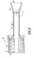
- the general structure of a rocket motor engine is shown in FIG. 2, in which the engine is generally designated by reference numeral 10.
- the illustrated rocket motor engine 10 includes a case 12 in which a rocket motor propellant 14 is housed, a nozzle assembly 20, and a blast tube 16 connecting the case 12 to the nozzle assembly 20.
- the propellant 14 is in the form of a solid propellant grain 14.
- the case 12 and the propellant grain 14 commonly are separated by an insulation layer 15, as well as a liner (not shown).
- the blast tube may also be lined with insulation, such as depicted in FIG. 2 and designated by reference numeral 18.
- the insulation 15 and the liner serve to protect the case 12 from the extreme conditions produced by the propellant 14 as the propellant 14 undergoes combustion reactions and is exhausted through exit region 24 of the nozzle assembly 20.
- the liner serves the additional functions of bonding the propellant 14 to the insulation 15 and the case 12, and creating a seal to prevent the penetration of hot combustion gases to the case 12.
- the illustrated embodiment is of a blast tube solid rocket motor nozzle, it is to be understood that the nozzle assembly of this invention can be applied to various other types of rocket motors that are mounted to or closer to the case 12, and that do not contain a blast tube 16.
- the principles of this invention can also be applied to hybrid systems and liquid oxidizer/liquid fuel systems (engines).
- the illustrated nozzle 20 defines a converging/diverging pathway having a throat of restricted cross-sectional area.
- the throat is generally designated by reference numeral 22.
- combustion products including hot exhaust gases, are generated by the rocket motor engine 10 and passed through the blast tube 16 and the throat 22.
- exit velocity of the combustion gases is increased to thereby increase thrust.
- the throat 22 is generally defined by an annular throat insert that comprises an annular throat support 30 and an annular shell 40.
- the shell 40 is positioned radially inside of the throat support 30 to cover at least a substantial portion of the radially inner surface of the throat support 30.
- the throat support 30 is made of one or more carbon-based materials, exemplary compositions of which are described in much greater detail below.
- the throat insert is annular in shape, and has a substantially flat outer surface 31 that seats against outer support shell 26, which is typically made of a metal.
- the radially inner surface of the throat support 30 includes a forward converging portion 32 that extends from a forward edge (or face) 34 of the throat support 30 to a minimum cross-sectional area portion at the throat 22. In the illustrated embodiment, the forward converging portion 32 curves towards the outer diameter of the rocket motor nozzle 20 for achieving better retention of the throat support 30. Aft of the throat 22, the inner surface of the throat support 30 expands along a diverging portion 36.
- aft skirt 28 configured as a diverging truncated cone.
- the aft skirt 28 and aft end surface 38 abut one another and can be connected by any conventional technique, including epoxy adhesives, other adhesives, and/or mechanical fastening means.
- the aft end surface 38 is machined at an angle relative to the aft skirt 28 to enhance the retention of the throat insert against high internal pressures.
- the aft skirt 28 is supported by outer support shell 26, which (although not shown) may coextend along the entire length of the aft skirt 28.
- the aft skirt 28 engages the outer support shell 26 via screw threads 29.
- the shell 40 covering the throat support 30 is made of one or more refractory metals and/or alloys having melting temperatures above 2700°C (4918°F), preferably above 2760°C (5000°F), more preferably above 3040°C (5500°F).
- refractory materials include tungsten, rhenium, tantalum, and alloys containing one or more of these refractory metals.
- tungsten is the preferred refractory metal
- tungsten is still more preferably used as an alloy with rhenium, which improves ductility.
- the alloy is 75-95 wt% tungsten, with the balance (5-25 wt%) rhenium.
- the thickness of the shell 40 is generally dependent upon the size of the nozzle employed.
- the shell 40 thickness can be in a range of from about 0.1 cm (40 mils) to about 0.15 cm (60 mils).
- the shell 40 thickness can be generally as large as about 0.3 cm (1/8 inch).
- the shell 40 thickness may be selected within or outside of these ranges, so long as the selected thickness does not result in undue amounts of thermal stress that significantly risk nozzle failure.
- the thermal stresses encountered by thermal expansion of the shell 40 are also mitigated by the throat support 30, which is formed of carbon-based materials that decompose/char during motor operation.
- the refractory metal shell 40 is able to expand more easily into the throat support 30 once the support 30 has undergone decomposition/charring.
- the annular shell 40 has a forward surface region 42 covering the entire forward converging portion 32 of the throat support 30. It is to be understood, however, that the forward surface region 42 of the shell 40 need only extend over the entire forward converging portion 32, i.e., the forward surface region 42 does not have to extend all the way to the forward edge 34 of the throat support 30.
- Formed contiguously and integrally with the forward surface region 42 is a throat surface region 44 of the shell 40.
- an aft surface region 46 of the shell 40 is formed contiguously and integrally with the throat surface region 44.
- the aft surface region 46 covers the diverging portion 36 of the throat support 30 in its entirety, it is to be understood that the aft surface region 46 is not required to extend to the aft end surface 38 of the throat support 30. However, the aft surface region 46 should extend sufficiently far along the diverging portion 36 of the throat support 30 to eliminate step-down erosion or at least reduce step-down erosion to non-appreciable levels. Step-down erosion will reduce motor thrust and should be minimized.
- the throat surface region 44 defines the throat area 22 of minimum cross section. In this manner, the throat surface region 44 is left exposed to hot combustion products passing through the nozzle 20 pathway during firing of the motor. Exposing the refractory metal of the shell 40, and in particular the refractory metal of the throat surface region 44 of the shell 40, at the throat 22 is an important feature of this invention. Refractory metals are much more resistant to step erosion than carbon-based materials. By defining the throat area 22 with the refractory shell 40, and not covering the throat surface region 44 of the shell 40 with carbon- or silica-based materials, the throat 22 remains substantially constant in cross-sectional area throughout engine operation because the refractory metal of the throat surface region 44 is not significantly eroded. As a consequence, improvements in performance and predictability of the rocket motor 10 can be realized.
- the forward surface region 42 of the shell 40 engages in abutting relationship insulation 18 of the blast tube 16. (Alternatively, in the event that the forward surface region 42 does not extend to the forward edge 34 of the throat support 30, thus leaving part of the forward converging portion 32 uncovered, then the insulation 26 would abut against the uncovered part of the forward converging portion 32 of the throat support 30.)
- annular protective liner 50 Covering the forward surface region 42 of the shell 40 and the forward converging portion 32 of the throat support 30 is an annular protective liner 50, which in the cross-sectional view of FIG. 1 has the general appearance of an eyelid.
- the protective liner 50 is formed from one or more carbon-based and/or silica-based ablative materials, which may be the same or different from the material from which the throat support 30 is made.
- the protective liner 50 extends sufficiently far forward towards the insulation 18 to cover the forward edge 34 of the throat insert, so as to prevent combustion products passing along the converging/diverging pathway during operation of the rocket motor from passing under (radially outward from) the forward edge 34 and reaching between the throat insert and the outer support shell 26.
- the protective liner 50 also extends over the entire forward surface region 42 and forward converging portion 32 to protect these components from particle impingement and heating and to provide some combination of boundary layer enhancement and/or transpiration cooling to the refractory shell 40. Because the protective liner 50 is made of a carbon-based and/or silica-based material that recedes during operation of the rocket motor, the protective liner 50 is preferably of sufficient thickness that the liner 50 is not completely eroded away during engine operation. It is to be understood that although the protective liner 50 is illustrated as extending over the entire forward surface region 42 of the liner 40, the protective liner 50 may extend only partway along the forward surface region 42.
- the protective liner 50 does not cover the throat surface region 44, which is made of a refractory material that is less susceptible to erosion than the protective liner 50.
- the throat 22 is defined by the refractory metals/alloys of the throat surface region 44 of the shell 40. Therefore, the throat 22 is less prone to erosion from the combustion products passing along the converging/diverging pathway 22 during operation of the rocket motor engine.
- a vacuum plasma spraying technique which involves spraying material onto a mandrel of the desired shape and subsequently removing the mandrel.
- the plasma is formed by passing gases such as argon and/or hydrogen through an electric arc positioned between an anode and cathode.
- the gas passing through the electric arc is ionized and generates temperatures on the order of 16,650°C (30,000°F).
- Refractory metal powder is entrained in a gas carrier, such as argon gas, and injected from a gun into the hot plasma.
- the powder is melted by the plasma and accelerated towards the surface of mandrel. If appropriate, the mandrel may be rotated during spraying.
- Advantages of the vacuum plasma spraying technique include the ability to form near-net-shape components that do not require laborious machining.
- nozzle support 30 about the radially outer surface of the refractory shell 40, as well as to form the protective liner 50 and the aft skirt 28.
- One highly advantageous technique is described in detail below.
- the refractory shell 40 can be insulated with the carbon-based throat support 30 by arranging a curable pre-preg around the outer surface of the refractory shell 40 at a level of compaction sufficiently low to permit voids to be generated therein during subsequent curing of the pre-preg, then curing the prepreg at a pressure sufficiently low to permit evolving gases to form voids in the pre-preg as the pre-preg cures to form the throat support 30.
- the pressure at which the pre-preg is cured is maintained at not more than about 150 psig.
- the prepreg can be arranged by winding a pre-preg tape or applying a pre-preg cloth about the refractory shell 40.
- the pre-preg tape can be applied using a tape wrap process in which the pre-preg tape is heated, such as by a hot air source, to soften the tape.
- the hot air can be supplied to the tape at a temperature in the range of about 177°C (350°F) to about 482°C (900°F), more typically in the range of about 177°C (350°F) to 288°C (550°F).
- the tape may be debulked as it wraps onto the refractory shell 40, for example, by setting a roller in close proximity to the refractory shell 40.
- the tapes may be debulked less than 80%, more particularly less than about 50%.
- the pressure applied by the roller and the refractory shell 40 is generally less than about half (50%) of the lowest pressure recommended by pre-preg vendors (100 to 300 pounds per inch of tape width) and about 50 pounds per inch of tape width is exemplary of such a lower pressure.
- the tape is cooled and preferably hardened as the tape is wrapped about the refractory shell 40. Carbon dioxide (or other coolant) from a liquid holding tank can be applied to the wrapped tape as the tape wraps about the refractory shell 40. This cools and hardens the wrapped tape about the refractory shell 40 whereby the throat support 30 is formed.
- the pressure can be vacuum or up to less than about atmospheric pressure.
- the wrapped throat support 30 and refractory shell 40 can be vacuum bagged using a vapor impermeable vacuum bag, such as a nylon vacuum bag, sealed with vacuum putty.
- a suitably thick or suitably layered bleeder material is used so that any resin bleed from the curing material does not clog vacuum lines or to avoid (if not minimize) adversely affect the vacuum bag itself.
- a bleeder material may comprise, for instance, at least one layer of perforated film; at least two layers of cotton mop; or at least two layers of bleeder material, such as a polyester bleeder material (about 10 oz or about 16 oz./sq. yard of polyester bleeder material).
- the vacuum bagged material is then cured using a selected maximum vacuum.
- the vacuum provides the only pressure applied during the curing, and low pressures on the order of sub-atmospheric up to about, preferably less than, atmospheric can be used, such as a vacuum equivalent of about 12.5 psia to less than about 14.7 psia, although the pressure selected will depend on the prevalent atmospheric pressure. Still lower pressures can also be used.
- the low pressure vacuum can, for instance, be in a range of from about 12.5 psia to about 14 psia, and more particularly in a range of from about 12.5 psia to about 12.7 psia.
- the cure pressure is adjusted to maintain or provide the desired cured component density.
- thermo cycling it is possible to use thermal cycling to cure the pre-preg.
- various temperatures or temperatures and residence times are selected to ensure the satisfactory curing of the composite article.
- An exemplary temperature cycle involves heating and cooling the pre-preg at a rate of about 0.55°C (1°F) per minute.
- a multi-stage temperature cycle can be used.
- the thermal cycling can be programmed to have a first hold at about 82°C (180°F) for a residence time of about 1.25-1.5 hours, a second hold at about 104°C (220°F) for a comparable residence time as the first hold, and a third hold at a temperature in a range of from about 154°C (310°F) to about 160°C (320°F) for about 60 or more minutes for each inch of component wall thickness.
- the residence time at a holding temperature will be a function of process variables, such as the thickness of the material to be cured.
- suitable curing cyclings including both residence times and cure temperatures, is within the purview of those skilled in the art and can be determined without undue experimentation.
- Suitable carbon-based pre-preg materials are generally characterized by a reinforcement (fibers, cloth, tape) to which is impregnated with a thermosetting resin.
- Suitable reinforcement can comprise wide variety of fibers or filaments (whether continuous or staple) known in the art. These fibers and filaments include, but are not limited to, glass fibers, boron filaments, boron nitride, silicon carbide, graphite (carbon) filaments and high modulus organic filaments, particularly organic filaments of the nylon, polyethylene, and aramid type. Examples of high modulus organic filaments include, but are not limited to, poly(benzothiazoles) and poly(aromatic amides) which are commonly referred to simply as "aramids".
- Aramids include poly (benzamides) and family of materials sold by E. I. DuPont under the trademark KEVLAR.
- carbon filaments useful in this invention there may be mentioned, for example, Amoco Performance Product's T-300 and Toray's T-800H and T-1000G carbon fibers.
- Suitable carbon-based thermosetting resins include, for example, phenolic resins, and epoxy resins (especially those based on diglycidyl ethers of bisphenol A are employed).
- bis-maleimide resins, polyurethanes, polyesters, and the like, and any combination thereof may also be employed as the carbon-base resin or a component thereof.
- a phenolic resin matrix resin for the pre-preg is used.
- Suitable commercially available curable phenolic resins are SC-I008 (Borden) and 91-LD phenolic resin (Stuart - Ironsides).
- Epoxy-based pre-pregs are not preferred for rocket motor nozzle components.
- a carbon cloth impregnated with a curable phenolic resin can also be used.
- the carbon cloth can be rayon-based, polyacrylonitrile (PAN) based, or pitch-based.
- PAN polyacrylonitrile
- These types of pre-pregs include the industry standard density pre-pregs such as MX-4926 (28-38% resin, 8-16% filler, the remainder including cloth reinforcement) which is a rayon based carbon phenolic pre-preg from Fiberite.
- Other suitable materials from Fiberite include PAN-based pre-pregs, such as those sold under the designations MX-4946 or MX-4920 which both used a T300 fiber/yarn which is a vendor designation for a yarn having a modulus of 300 million.
- Other "T" type fiber/yarn products can be used.
- These materials can include a filler, and generally include carbon powder filler.
- Graphite cloth phenolics can be used.
- the graphite fiber can be rayon, PAN or pitch based.
- Suitable commercially available graphite pre-pregs include Fiberite products sold under the designations MXG-175 (graphite which is rayon based) and MX-4961 (graphite which is PAN based).
- Glass cloth pre-pregs include a glass fiber reinforced phenolic resin such as MXB-6001 from Fiberite.
- Silica fiber reinforced phenolic resin such as a product from Fiberite known as MX-2600, can be used.
- the pre-preg materials can, if desired, include filler materials. Suitable filler materials include silica, carbon powder and others known to those skilled in the art. Filler materials can serve more than one function. For instance, some fillers, including powdered alumina trihydrate or antimony oxide, may also provide some flame resistance, or other characteristics to the final cured products, but are nonetheless fillers.
- the present process does not require, and preferably avoids the use of hollow microspheres (and elastomers) in order to produce a low density composite article.
- the present invention is not limited to production of the carbon-based insulation materials, including the protection liner, by the above-discussed technique, it is noted that this technique produces rocket nozzle components that exhibit remarkable erosion resistance and charring to similar high density products.
- This technique resides in forming and curing the insulation at sufficiently low pressures to permit the formation of volatiles that generate voids in the resulting product, without requiring low density fillers, such as hollow spheres ("microballons").
- the cured articles prepared in accordance with this technique have a specific gravity which is lower than standard density composite rocket nozzle. For instance, with a suitable carbon phenolic resin based pre-preg, a lower density (SpG) in a range of about 1.00 (e.g.
- cured articles of the present invention also exhibit across ply tensile strengths which may be greater than, or at least near to, those observed with well-prepared composites from standard density pre-pregs.
- the composite rocket nozzles of our invention can have an across ply tensile strength of about 124,1 bars to about 206,8 bars (1800 to about 3000 psig), and more particularly can be readily prepared to have across ply tensile strengths of 124,1 bars to 151,7 bag (1800 to 2200 psig).
- Across ply properties of the composite material can be tailored by adjusting the pressure used in the initial compaction step and pressure used in the cure step. Such adjustments are techniques that, when viewed in reference to this disclosure, would be within the purview of the skilled artisan without undue experimentation.
Landscapes
- Chemical & Material Sciences (AREA)
- Engineering & Computer Science (AREA)
- Mechanical Engineering (AREA)
- Chemical Kinetics & Catalysis (AREA)
- Materials Engineering (AREA)
- Metallurgy (AREA)
- Organic Chemistry (AREA)
- Plasma & Fusion (AREA)
- Physics & Mathematics (AREA)
- Combustion & Propulsion (AREA)
- General Engineering & Computer Science (AREA)
- Furnace Housings, Linings, Walls, And Ceilings (AREA)
- Physical Or Chemical Processes And Apparatus (AREA)
Claims (24)
- Düsenvorrichtung (20), welche einen zusammenlaufenden/auseinanderlaufenden Durchgang mit einer Engstelle (22) und einen Austrittsbereich besitzt, wobei die Düsenvorrichtung funktionell mit einem Raketenmotorgehäuse (12) in Eingriff bringbar ist, um Hochtemperaturverbrennungsprodukte aufzunehmen, welche im Raketenmotorgehäuse infolge der Zündung eines Treibstoffs (14) erzeugt werden, welcher in das Raketenmotorgehäuse eingebracht worden ist, und um die Verbrennungsprodukte durch die Engstelle durchzuleiten, bevor die Verbrennungsprodukte von dem Austrittsbereich ausgestoßen werden, wobei die Düsenvorrichtung umfasst:(i) einen ringförmigen Engstelleneinsatz, welcher einen ringförmigen Engstellenträger (30) und eine ringförmige Hülle (40), welche innerhalb des Engstellenträgers radial angeordnet ist, umfasst, wobei der Engstellenträger mindestens ein Kohlenstoff-basiertes Material umfasst und eine Vorderfläche oder Vorderkante (34), einen innen radial zusammenlaufenden Abschnitt (32), welcher zu einem minimalen Querschnittsflächenabschnitt an der Engstelle zusammenläuft, und hinter dem minimalen Querschnittsflächenabschnitt einen innen radial auseinanderlaufenden Abschnitt (36) besitzt;(ii) die Hülle, welche mindestens ein feuerfestes Metall oder eine feuerfeste Metalllegierung umfasst, besitzt(a) einen vorderen Oberflächenbereich (42), welcher mindestens einen Abschnitt des zusammenlaufenden Abschnitts des Engstellenträgers abdeckt;(b) einen Engstellenoberflächenbereich (44), welcher den minimalen Querschnittsflächenabschnitt des Engstellenträgers abdeckt, wobei der Engstellenoberflächenbereich die Engstelle definiert und entlang des zusammenlaufenden/auseinanderlaufenden Durchgangs freiliegt; und(c) einen hinteren Oberflächenbereich (46), welcher mindestens einen Abschnitt des auseinanderlaufenden Abschnitts des Engstellenträgers abdeckt;(iii) ein Schutzaugenlid (50), welches mindestens ein Teil umfasst, welches aus der aus einem Kohlenstoff-basierten Material und einem Siliziumdioxid-basierten Material bestehenden Gruppe ausgewählt ist, wobei das Schutzaugenlid die Vorderfläche oder Vorderkante des Engstellenträgers abdeckt, um zu verhindern, dass die Verbrennungsprodukte, welche entlang des zusammenlaufenden/auseinanderlaufenden Durchgangs strömen, eine radial äußere Oberfläche des Engstelleneinsatzes erreichen, wobei jedoch das Schutzaugenlid den Engstellenoberflächenbereich der Hülle nicht abdeckt, so dass der Engstellenoberflächenbereich der Hülle den Verbrennungsprodukten ausgesetzt bleibt, die während des Betriebs einer Raketenmotorvorrichtung, welche im Betrieb der Düsenvorrichtung zugeordnet ist, entlang des zusammenlaufenden/auseinanderlaufenden Durchgangs strömen; und(iv) eine hintere Einfassung (28), welche als ein auseinanderlaufender Kegelstumpf ausgestaltet ist, wobei die hintere Einfassung von dem Engstelleneinsatz aus nach hinten verläuft.
- Düsenvorrichtung nach Anspruch 1,
wobei das feuerfeste Metall oder die feuerfeste Metalllegierung eine Schmelztemperatur von über 2760°C besitzt. - Düsenvorrichtung nach Anspruch 1,
wobei die Hülle (40) durch ein Vakuumplasmaspritzverfahren ausgebildet ist. - Düsenvorrichtung nach Anspruch 1,
wobei das mindestens eine feuerfeste Metall oder die mindestens eine feuerfeste Metalllegierung eine Komponente umfasst, welche aus der aus Wolfram, Rhenium, Tantal oder einer Legierung davon bestehenden Gruppe ausgewählt ist. - Düsenvorrichtung nach Anspruch 1,
wobei das mindestens eine feuerfeste Metall oder die mindestens eine feuerfeste Metalllegierung eine Wolfram-Rheniumlegierung umfasst. - Düsenvorrichtung nach Anspruch 1,
wobei die Hülle (40) eine Dicke von 0,1 cm bis 0,3 cm besitzt. - Düsenvorrichtung nach Anspruch 1,
wobei der vordere Oberflächenbereich (42) den zusammenlaufenden Abschnitt (32) des Engstellenträgers (30) vollständig abdeckt und der hintere Oberflächenbereich (46) den auseinanderlaufenden Abschnitt (36) des Engstellenträgers (30) vollständig abdeckt. - Düsenvorrichtung nach Anspruch 1,
wobei das Schutzaugenlid (50) den vorderen Oberflächenbereich (42) der Hülle (40) vollständig abdeckt. - Raketenmotorvorrichtung umfassend:(A) ein Raketenmotorgehäuse (12), welches eine Verbrennungskammer und mindestens einen Treibstoff (14), welcher zündfähig ist, um Hochtemperaturverbrennungsprodukte zu erzeugen, umfasst; und(B) eine Düsenvorrichtung (20), welche einen zusammenlaufenden/auseinanderlaufenden Durchgang mit einer Engstelle (22) und einen Austrittsbereich besitzt, wobei die Düsenvorrichtung funktionell mit dem Raketenmotorgehäuse in Eingriff bringbar ist, um die von dem Treibstoff erzeugten Verbrennungsprodukte aufzunehmen und die Verbrennungsprodukte durch den zusammenlaufenden/auseinanderlaufenden Durchgang durchzuleiten, bevor die Verbrennungsprodukte von dem Austrittsbereich für den Vortrieb ausgestoßen werden und/oder von der Raketenmotorvorrichtung abgeleitet werden, wobei die Düsenvorrichtung umfasst:(i) einen ringförmigen Engstelleneinsatz, welcher einen ringförmigen Engstellenträger (30) und eine ringförmige Hülle (40), welche innerhalb des Engstellenträgers radial angeordnet ist, umfasst, wobei der Träger mindestens ein Kohlenstoff-basiertes Material umfasst und eine Vorderfläche oder Vorderkante (34), einen innen radial zusammenlaufenden Abschnitt (32), welcher zu einem minimalen Querschnittsflächenabschnitt an der Engstelle zusammenläuft, und hinter dem minimalen Querschnittsflächenabschnitt einen innen radial auseinanderlaufenden Abschnitt (36) besitzt;(ii) die ringförmige Hülle, welche mindestens ein feuerfestes Metall oder eine feuerfeste Metalllegierung umfasst, umfasst:(a) einen vorderen Oberflächenbereich (42), welcher mindestens einen Abschnitt des zusammenlaufenden Abschnitts des Engstellenträgers abdeckt;(b) einen Engstellenoberflächenbereich (44), welcher den minimalen Querschnittsflächenabschnitt des Engstellenträgers abdeckt, wobei der Engstellenoberflächenbereich die Engstelle definiert und entlang des zusammenlaufenden/auseinanderlaufenden Durchgangs freiliegt; und(c) einen hinteren Oberflächenbereich (46), welcher mindestens einen Abschnitt des auseinanderlaufenden Abschnitts des Engstellenträgers abdeckt;(iii) ein Schutzaugenlid (50), welches mindestens ein Teil umfasst, welches aus der aus einem Kohlenstoff-basierten Material und einem Siliziumdioxid-basierten Material bestehenden Gruppe ausgewählt ist, wobei das Schutzaugenlid einen ausreichenden Abschnitt des vorderen Oberflächenbereichs der Hülle abdeckt, um die Hülle zu isolieren und zu verhindern, dass die Verbrennungsprodukte, welche entlang des zusammenlaufenden/auseinanderlaufenden Durchgangs strömen, eine radial äußere Oberfläche des Engstelleneinsatzes erreichen, wobei jedoch das Schutzaugenlid den Engstellenoberflächenbereich der Hülle nicht abdeckt, so dass der Engstellenoberflächenbereich der Hülle den Verbrennungsprodukten ausgesetzt bleibt, die während des Betriebs der Raketenmotorvorrichtung entlang des zusammenlaufenden/auseinanderlaufenden Durchgangs strömen; und(iv) eine hintere Einfassung (28), welche als ein auseinanderlaufender Kegelstumpf ausgestaltet ist, wobei die hintere Einfassung von dem Engstelleneinsatz aus nach hinten verläuft.
- Raketenmotorvorrichtung nach Anspruch 9,
wobei das feuerfeste Metall oder die feuerfeste Metalllegierung eine Schmelztemperatur von über 2760°C besitzen. - Raketenmotorvorrichtung nach Anspruch 9,
wobei die Hülle (40) mit einem Vakuumplasmaspritzverfahren ausgebildet ist. - Raketenmotorvorrichtung nach Anspruch 9,
wobei das mindestens eine feuerfeste Metall oder die mindestens eine feuerfeste Metalllegierung eine Komponente umfasst, welche aus der aus Wolfram, Rhenium, Tantal oder einer Legierung davon bestehenden Gruppe ausgewählt ist. - Raketenmotorvorrichtung nach Anspruch 9,
wobei das mindestens eine feuerfeste Metall oder die mindestens eine feuerfeste Metalllegierung eine Wolfram-Rheniumlegierung umfasst. - Raketenmotorvorrichtung nach Anspruch 9,
wobei die Hülle (40) eine Dicke von 0,1 cm bis 0,3 cm besitzt. - Raketenmotorvorrichtung nach Anspruch 9,
wobei der vordere Oberflächenbereich (42) den zusammenlaufenden Abschnitt (32) des Engstellenträgers (30) vollständig abdeckt und der hintere Oberflächenbereich (46) den auseinanderlaufenden Abschnitt (36) des Engstellenträgers (30) vollständig abdeckt. - Raketenmotorvorrichtung nach Anspruch 9,
wobei das Schutzaugenlid (50) den vorderen Oberflächenbereich (42) der Hülle (40) vollständig abdeckt. - Verfahren zur Herstellung einer Raketenmotordüsenvorrichtung (20), welche einen zusammenlaufenden-auseinanderlaufenden Durchgang mit einer Engstelle (22) und einen Austrittsbereich besitzt, wobei die Düsenvorrichtung funktionell mit einem Raketenmotorgehäuse (12) in Eingriff bringbar ist, um Hochtemperaturverbrennungsprodukte aufzunehmen, welche in dem Raketenmotorgehäuse infolge der Zündung eines Treibstoffs (14) erzeugt werden, welcher in das Raketenmotorgehäuse eingebracht worden ist, und um die Verbrennungsprodukte durch die Engstelle durchzuleiten, bevor die Verbrennungsprodukte von dem Austrittsbereich ausgestoßen werden, wobei das Verfahren umfasst:(A) Bilden einer ringförmigen Hülle (40) durch ein Plasmaspritzverfahren mit wenigstens einem feuerfesten Metall oder einer feuerfesten Metalllegierung; und(B) Bilden einer Raketenmotordüse umfassend:(i) einen ringförmigen Engstelleneinsatz, welcher einen ringsförmigen Engstellenträger (30) und die Hülle umfasst, wobei der Engstellenträger mindestens ein Kohlenstoff-basiertes Material umfasst und eine Vorderfläche oder Vorderkante (34), einen innen radial zusammenlaufenden Abschnitt (32), welcher zu einem minimalen Querschnittsflächenabschnitt an der Engstelle zusammenläuft, und hinter dem minimalen Querschnittsflächenabschnitt einen innen radial auseinanderlaufenden Abschnitt (36) besitzt;(ii) die Hülle, welche innerhalb der Engstelle radial angeordnet ist, umfasst:(a) einen vorderen Oberflächenbereich (42), welcher mindestens einen Abschnitt des zusammenlaufenden Abschnitts des Engstellenträgers abdeckt;(b) einen Engstellenoberflächenbereich (44), welcher den minimalen Querschnittsflächenabschnitt des Engstellenträgers abdeckt, wobei der Engstellenoberflächenbereich die Engstelle definiert und entlang des zusammenlaufenden/auseinanderlaufenden Durchgangs freiliegt; und(c) einen hinteren Oberflächenbereich (46), welcher mindestens einen Abschnitt des auseinanderlaufenden Abschnitts des Engstellenträgers abdeckt;(iii) ein Schutzaugenlid (50), welches mindestens ein Teil umfasst, welches aus der aus einem Kohlenstoff-basierten Material und einem Siliziumdioxid-basierten Material bestehenden Gruppe ausgewählt ist, wobei das Schutzaugenlid einen ausreichenden Abschnitt des vorderen Oberflächenbereichs der Hülle abdeckt, um die Hülle zu isolieren und die Vorderfläche oder Vorderkante des Engstellenträgers abzudecken, um zu verhindern, dass die Verbrennungsprodukte, welche entlang des zusammenlaufenden-auseinanderlaufenden Durchgangs strömen, eine radial äußere Oberfläche des Engstelleneinsatzes erreichen, wobei jedoch das Schutzaugenlid den Engstellenoberflächenbereich der Hülle nicht abdeckt, so dass der Engstellenoberflächenbereich der Hülle den Verbrennungsprodukten ausgesetzt bleibt, die während des Betriebs einer Raketenmotorvorrichtung, welche im Betrieb der Raketenmotordüsenvorrichtung zugeordnet ist, entlang des zusammenlaufenden-auseinanderlaufenden Durchgangs strömen; und(iv) eine hintere Einfassung (28), welche als ein auseinanderlaufender Kegelstumpf ausgestaltet ist, wobei die hintere Einfassung von dem Engstelleneinsatz aus nach hinten verläuft.
- Verfahren nach Anspruch 17,
wobei das feuerfeste Metall oder die feuerfeste Metalllegierung eine Schmelztemperatur von über 2760°C besitzt. - Verfahren nach Anspruch 17,
wobei das mindestens eine feuerfeste Metall oder die mindestens eine feuerfeste Metalllegierung eine Komponente umfasst, welche aus der aus Wolfram, Rhenium, Tantal und einer Legierung davon bestehenden Gruppe ausgewählt ist. - Verfahren nach Anspruch 17,
wobei das mindestens eine feuerfeste Metall oder die mindestens eine feuerfeste Metalllegierung eine Wolfram-Rheniumlegierung umfasst. - Verfahren nach Anspruch 17,
wobei die Hülle eine Dicke von 0,1 cm bis 0,3 cm besitzt. - Verfahren nach Anspruch 17,
wobei der vordere Oberflächenbereich (42) den zusammenlaufenden Abschnitt (32) des Engstellenträgers (30) vollständig abdeckt und der hintere Oberflächenbereich (46) den auseinanderlaufenden Abschnitt (36) des Engstellenträgers vollständig abdeckt. - Verfahren nach Anspruch 17,
wobei das Schutzaugenlid (50) den vorderen Oberflächenbereich (42) der Hülle (40) vollständig abdeckt. - Verfahren nach einem der Ansprüche 17-23,
wobei das Plasmaspritzverfahren ein Vakuumplasmaspritzverfahren umfasst.
Applications Claiming Priority (3)
| Application Number | Priority Date | Filing Date | Title |
|---|---|---|---|
| US17721800P | 2000-01-21 | 2000-01-21 | |
| US177218P | 2000-01-21 | ||
| PCT/US2001/001930 WO2001053683A1 (en) | 2000-01-21 | 2001-01-19 | Rocket motor nozzle assembly comprising a refractory metal shell |
Publications (2)
| Publication Number | Publication Date |
|---|---|
| EP1248902A1 EP1248902A1 (de) | 2002-10-16 |
| EP1248902B1 true EP1248902B1 (de) | 2005-04-13 |
Family
ID=22647688
Family Applications (1)
| Application Number | Title | Priority Date | Filing Date |
|---|---|---|---|
| EP01926336A Expired - Lifetime EP1248902B1 (de) | 2000-01-21 | 2001-01-19 | Raketendüse mit hochtemperaturfestem schutzschild |
Country Status (4)
| Country | Link |
|---|---|
| EP (1) | EP1248902B1 (de) |
| JP (1) | JP2003520322A (de) |
| AU (1) | AU2001252880A1 (de) |
| WO (1) | WO2001053683A1 (de) |
Families Citing this family (4)
| Publication number | Priority date | Publication date | Assignee | Title |
|---|---|---|---|---|
| KR100997902B1 (ko) | 2008-12-31 | 2010-12-02 | 한국항공우주연구원 | 액체로켓엔진 노즐 확장부 조립장치 |
| CN109918699B (zh) * | 2018-12-03 | 2022-12-09 | 西安航天动力技术研究所 | C/c复合材料喉衬性能的关键参数识别方法 |
| CN114199135B (zh) * | 2021-11-26 | 2024-07-09 | 南京理工大学 | 喉衬内型面退移量、碳化层厚度的测量装置及方法 |
| CN118815618B (zh) * | 2024-09-18 | 2025-07-01 | 陕西普利美材料科技有限公司 | 一种固体火箭喷管复合扩张段及其成型方法 |
Family Cites Families (3)
| Publication number | Priority date | Publication date | Assignee | Title |
|---|---|---|---|---|
| US3139672A (en) * | 1961-02-10 | 1964-07-07 | Bendix Corp | Rocket nozzles and the like |
| US3265314A (en) * | 1963-09-13 | 1966-08-09 | Gen Motors Corp | Heat dispersing swivel rocket nozzle liner |
| US3441217A (en) * | 1966-11-16 | 1969-04-29 | Thiokol Chemical Corp | Noneroding rocket nozzle |
-
2001
- 2001-01-19 EP EP01926336A patent/EP1248902B1/de not_active Expired - Lifetime
- 2001-01-19 AU AU2001252880A patent/AU2001252880A1/en not_active Abandoned
- 2001-01-19 JP JP2001553521A patent/JP2003520322A/ja not_active Withdrawn
- 2001-01-19 WO PCT/US2001/001930 patent/WO2001053683A1/en not_active Ceased
Also Published As
| Publication number | Publication date |
|---|---|
| EP1248902A1 (de) | 2002-10-16 |
| WO2001053683A1 (en) | 2001-07-26 |
| JP2003520322A (ja) | 2003-07-02 |
| AU2001252880A1 (en) | 2001-07-31 |
Similar Documents
| Publication | Publication Date | Title |
|---|---|---|
| US6711901B1 (en) | Rocket motor nozzle assemblies having vacuum plasma-sprayed refractory metal shell throat inserts, methods of making, and rocket motors including same | |
| AU2008295569B2 (en) | Integral composite rocket motor dome/nozzle structure | |
| US7238414B2 (en) | Fiber-reinforced composite for protective armor, and method for producing the fiber-reinforced composition and protective armor | |
| KR100787318B1 (ko) | 분해 가능한 스러스트 벡터 제어 베인 | |
| CA1079078A (en) | Rocket nozzle assembly | |
| US6436480B1 (en) | Thermal spray forming of a composite material having a particle-reinforced matrix | |
| EP1373386B1 (de) | Faserverstärkte isolierung für raketenmotoren | |
| CN102741646A (zh) | 防御性的陶瓷基贴花装甲,提供抗射弹的装甲保护的装置,和生产具有中空几何形状的陶瓷基射弹装甲的方法 | |
| WO2025064578A1 (en) | Heavy inert gas insulated rocket engine blast tube | |
| EP1248902B1 (de) | Raketendüse mit hochtemperaturfestem schutzschild | |
| US6209312B1 (en) | Rocket motor nozzle assemblies with erosion-resistant liners | |
| JP2001192275A (ja) | セラミックマトリックスを含む繊維強化複合材料からなる要素 | |
| AU2024344508A1 (en) | Vacuum insulated blast tube | |
| US20070128421A1 (en) | Refractory composite | |
| US5359850A (en) | Self venting carbon or graphite phenolic ablatives | |
| EP2567948B1 (de) | Verfahren zur Modifizierung von Verbundstoffartikeln | |
| US5645219A (en) | Addition-polymerization resin systems for fiber-reinforced nozzle ablative components | |
| Meiirbekov et al. | Multimatrix Composite Materials for Rocket Nozzle Manufacturing: A Comparative Review | |
| US7037602B2 (en) | Multilayer composite | |
| Meiirbekov et al. | Results in Engineering | |
| US20060144037A1 (en) | Rocket nozzle material | |
| US12606497B2 (en) | Systems and methods for limiting void formation in ceramic matrix composite components | |
| Lacombe | HERAKLES thermal-structural composite materials boost rocket nozzle performance | |
| Buckley | Carbon-carbon composites | |
| US20250334089A1 (en) | Rocket motor liner structure |
Legal Events
| Date | Code | Title | Description |
|---|---|---|---|
| PUAI | Public reference made under article 153(3) epc to a published international application that has entered the european phase |
Free format text: ORIGINAL CODE: 0009012 |
|
| 17P | Request for examination filed |
Effective date: 20020722 |
|
| AK | Designated contracting states |
Kind code of ref document: A1 Designated state(s): AT BE CH CY DE DK ES FI FR GB GR IE IT LI LU MC NL PT SE TR |
|
| AX | Request for extension of the european patent |
Free format text: AL;LT;LV;MK;RO;SI |
|
| RBV | Designated contracting states (corrected) |
Designated state(s): AT BE FR GB |
|
| 17Q | First examination report despatched |
Effective date: 20040416 |
|
| REG | Reference to a national code |
Ref country code: DE Ref legal event code: 8566 |
|
| GRAP | Despatch of communication of intention to grant a patent |
Free format text: ORIGINAL CODE: EPIDOSNIGR1 |
|
| RBV | Designated contracting states (corrected) |
Designated state(s): FR GB |
|
| GRAS | Grant fee paid |
Free format text: ORIGINAL CODE: EPIDOSNIGR3 |
|
| GRAA | (expected) grant |
Free format text: ORIGINAL CODE: 0009210 |
|
| AK | Designated contracting states |
Kind code of ref document: B1 Designated state(s): FR GB |
|
| REG | Reference to a national code |
Ref country code: GB Ref legal event code: FG4D |
|
| REG | Reference to a national code |
Ref country code: IE Ref legal event code: FG4D |
|
| PLBE | No opposition filed within time limit |
Free format text: ORIGINAL CODE: 0009261 |
|
| STAA | Information on the status of an ep patent application or granted ep patent |
Free format text: STATUS: NO OPPOSITION FILED WITHIN TIME LIMIT |
|
| ET | Fr: translation filed | ||
| 26N | No opposition filed |
Effective date: 20060116 |
|
| PGFP | Annual fee paid to national office [announced via postgrant information from national office to epo] |
Ref country code: FR Payment date: 20110301 Year of fee payment: 11 |
|
| PGFP | Annual fee paid to national office [announced via postgrant information from national office to epo] |
Ref country code: GB Payment date: 20110125 Year of fee payment: 11 |
|
| GBPC | Gb: european patent ceased through non-payment of renewal fee |
Effective date: 20120119 |
|
| REG | Reference to a national code |
Ref country code: FR Ref legal event code: ST Effective date: 20120928 |
|
| PG25 | Lapsed in a contracting state [announced via postgrant information from national office to epo] |
Ref country code: GB Free format text: LAPSE BECAUSE OF NON-PAYMENT OF DUE FEES Effective date: 20120119 |
|
| PG25 | Lapsed in a contracting state [announced via postgrant information from national office to epo] |
Ref country code: FR Free format text: LAPSE BECAUSE OF NON-PAYMENT OF DUE FEES Effective date: 20120131 |