US3441217A - Noneroding rocket nozzle - Google Patents
Noneroding rocket nozzle Download PDFInfo
- Publication number
- US3441217A US3441217A US594823A US3441217DA US3441217A US 3441217 A US3441217 A US 3441217A US 594823 A US594823 A US 594823A US 3441217D A US3441217D A US 3441217DA US 3441217 A US3441217 A US 3441217A
- Authority
- US
- United States
- Prior art keywords
- nozzle
- erosion
- insert
- rocket
- throat
- Prior art date
- Legal status (The legal status is an assumption and is not a legal conclusion. Google has not performed a legal analysis and makes no representation as to the accuracy of the status listed.)
- Expired - Lifetime
Links
Images
Classifications
-
- F—MECHANICAL ENGINEERING; LIGHTING; HEATING; WEAPONS; BLASTING
- F02—COMBUSTION ENGINES; HOT-GAS OR COMBUSTION-PRODUCT ENGINE PLANTS
- F02K—JET-PROPULSION PLANTS
- F02K9/00—Rocket-engine plants, i.e. plants carrying both fuel and oxidant therefor; Control thereof
- F02K9/80—Rocket-engine plants, i.e. plants carrying both fuel and oxidant therefor; Control thereof characterised by thrust or thrust vector control
- F02K9/82—Rocket-engine plants, i.e. plants carrying both fuel and oxidant therefor; Control thereof characterised by thrust or thrust vector control by injection of a secondary fluid into the rocket exhaust gases
-
- F—MECHANICAL ENGINEERING; LIGHTING; HEATING; WEAPONS; BLASTING
- F02—COMBUSTION ENGINES; HOT-GAS OR COMBUSTION-PRODUCT ENGINE PLANTS
- F02K—JET-PROPULSION PLANTS
- F02K9/00—Rocket-engine plants, i.e. plants carrying both fuel and oxidant therefor; Control thereof
- F02K9/97—Rocket nozzles
- F02K9/974—Nozzle- linings; Ablative coatings
Definitions
- This invention relates to nozzles for rocket motors and the like. More particularly, it relates to unique means for enhancing erosion resistance of rocket' thrust nozzles.
- the best ⁇ erosion resisting, i.e., noneroding, nozzle throat inserts have been-manufactured by metal spinning and/orv forging techniques using metals such as tungsten, tantalum, molybdenum, and the like.
- inserts have been made from graphite and/,or ceramics such as metal oxides, borides, silicides, nitrides and carbides wherein the metal constituents are aluminum, chromium, magnesium, zirconium, titanium, molybdenum, tungsten and tantalum and in yet other instances composite materials known as cermets which consist of intimate mixtures of the ceramics exemplified above and additional metallic components including those noted and others such as nickel, cobalt, iron, stainless steel, Inconel metal, Hastelloy, Vitalium, silver, platinum and beryllium.
- ceramics such as metal oxides, borides, silicides, nitrides and carbides wherein the metal constituents are aluminum, chromium, magnesium, zirconium, titanium, molybdenum, tungsten and tantalum and in yet other instances composite materials known as cermets which consist of intimate mixtures of the ceramics exemplified above and additional metallic components including those noted and others such as nickel, cobal
- 'It is another object of this invention to provide a nozzle insert of the type described wherein a metal welding technique is utilized to form a major portion thereof.
- Still another object of this invention is to provide a motor insert of the character noted wherein a metal erosion barrier is combined with a non-metal -base material to form the nozzle throat in a very large rocket booster motor.
- a still further object of this invention is to provide a throat insert for a rocket booster motor of large diameter wherein an erosion barrier consisting of a sheet of tungsten, tantalum, titanium, and/ or molybdenum is endjoined by welding in a frusto-conical form and oriented in a non-metal base material in a particular manner.
- FIGURE 1 is a partially-sectional side elevation of a rocket thrust nozzle embodying the preferred form of the invention.
- FIGURE 2 is similar to FIGURE 1, but shows an alternate embodiment of the invention.
- a preferred form of the invention depicted therein comprises a nozzle assembly 10 having an outer metal case or shell 24 surrounding a throat section 11 and an expansion cone 12.
- Shell 24 is supported in the region where it encloses throat section 11 by an outer reinforcing jacket or shroud 25 having an integral mounting ange 22.
- Throat section 11 includes an insert retaining member or piece 13 fitted at its outer periphery to the inside wall of shell 24 by adhesive bonding.
- Retaining member 13 has a machined aft or downstream face 14 and an annular upstream or forward face 15 which converges aftwardly.
- An annular base member or throat piece 16 is also attached to the inside wall of shell 24 by adhesive bonding and has a machined forward or upstream face 17 and an aft or downstream face 18 which abuts a liner 21 in expansion cone 12.
- Faces 14 of retainers 13 and 17 of base 16 are angularly machined so that when installed in shell 24 they are in parallel relation and separated by an erosion barrier or insert 19.
- Barrier or insert 19 is formed with sloping sides in frusto-conical shape of refractory metal such as tungsten, molybdenum, tantalum or titanium and is positioned lbetween faces 14 and 17, with its smaller or minor diameter downstream forming throat 20.
- insert 19 is of frusto-conical shape having an angle designated by the Greek letter theta (0), preferably ranging from about 15 to about 20, between its sloping slide and a line parallel to the axis of the nozzle 10.
- Insert 19 is the heart of this invention and is easily fabricated using current forming techniques well known in the art.
- insert 19 can easily be made from tungsten rolled sheet, which is commercially available in thicknesses ranging from about 0.100 inch to 0.250 inch.
- tungsten rolled sheet which is commercially available in thicknesses ranging from about 0.100 inch to 0.250 inch.
- a sheet of rolled tungsten a sheet having a thickness of 0.150 inch, was cut into a ribbon in suitable dimension and its ends joined and welded, resulting in the frusto-conical shape shown and positioned on surface or face 17 of base 16 by adhesive bonding.
- Retaining piece 13 is then placed in the conical portion of insert 19 with face 14 bearing against the inside surface thereof by adhesive bonding.
- Insert 19 is arranged between retainer 13 and base 16 with a small.
- Nozzle 10 is completed by installation of liner 21 in expansion cone 12 after which it is installed on a rocket motor (not shown) by conventional bolting by means of attaching flange 22.
- Material selected for retainer 13, base 16, and liner 21 is preferably graphite, although other materials such as the ceramics and cermets above mentioned are also suitable depending on operating motor conditions.
- Many plastice resins including the phenolics, silicones, malonates, polyesters, melamines, polyamides, epoxies and the ureas, with orwithout filler materials such as asbestos, and cotton, wool and nylon flock and the like may also be used for specific applications.
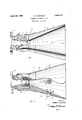
- FIGURE 2 illustrates an alternate embodiment of the invention, for use in rockets having extremely erosive propulsive gases. It is essentially the same as the embodiment of FIGURE 1, except that a series of refractory members 19 similar to erosion barrier 19 is used in places of otherwise heavy erosion. Accordingly, all parts of the nozzle 10 are identical to those described for nozzle 10 ⁇ except that outer shell 24', liner 21', retaining members 13' and erosion barrier 19 are all modified relative to their counterparts 24, 21, 13, and 19, respectively.
- the outer shell 24 and liner 21' are perforated to receive four tubes 26, equally spaced circumferentially in the expansion cone 12.
- the tubes 26 are used for selectively injecting a pressurized fluid from a source (not shown) into the expansion cone via pipes 27 to divert the propulsive gases and, thereby, steer the rocket.
- a series of annular, successively-larger-diameter erosion barriers 19" embedded in the liner 21 surrounds each tube 26 at the interior surface 28 of expansion cone l2 to protect these orifices from erosion.
- the forward retaining member 13 is divided into a plurality of annuli 13' having conical surfaces alternately arranged with a tandem series of erosion barriers 19 similar to the erosion barrier 19 of FIG- URE 1.
- the erosion barriers 19 and retaining members 13' function in a manner identical to members 13 and 19 of FIGURE 1 and are similarly fixed to adjacent parts by adhesive bonding.
- a rocket motor of the type comprising an outer shell and refractory material fixed to the inner surfaces thereof, said refractory material internally contoured to define a converging-diverging passage therethrough, the improvement comprising:
- At least one refractory metal insert formed from a ribbon of thin sheet metal stock and rolled to a frustoconical shape, said insert disposed in said refractory material around said passage having its base portion upstream and its top portion downstream, said top portion emerging from said material and terminating in a plane proximate the throat of said nozzle.
- the rocket motor nozzle of claim 1 wherein the refractory metal of said insert is selected from the group consisting of tungsten, molybdenum, tantalum, stainless steel, Inconel metal, nickel and alloys thereof.
- the rocket nozzle of claim 1 wherein the diverging portion of said refractory material and said shell, has at least one perforation therethrough, a tube in said perforation defining an orifice for injecting fiuid into said converging portion of said nozzle, and a plurality of annular, substantially concentric refractory metal erosion barriers embedded in said refractory material surrounding said tube.
- refractory metal of said erosion barriers is selected from the group consisting of tungsten, molybdenum, tantalum, stainless steel, Inconel metal, nickel and alloys thereof.
Landscapes
- Engineering & Computer Science (AREA)
- Chemical & Material Sciences (AREA)
- Combustion & Propulsion (AREA)
- Mechanical Engineering (AREA)
- General Engineering & Computer Science (AREA)
- Pressure Welding/Diffusion-Bonding (AREA)
Description
Aprill 29, 1969 H. H. MclNTo'sH 3,441,217
` NONEROYDING ROCKET NOZZIJE 4 Filed Nov. 16, 196e FIG- 2 INVENTOR.
' HowARo H. MemTosH mir/fm, www
AGFNT United States Patent Olhce 3,441,217 Patented Apr. 29, 1969 U.S. Cl. Z39-265.15 4 Claims SABSTRACT F THE DISCLOSURE A rocket motor and nozzle wherein airefractory material insert is bonded to the nozzle interior, surfaces and a thin sheet of refractory metal is disposed in the refractory material so as to materially enhance the erosion resistance qualities thereof. i
This invention relates to nozzles for rocket motors and the like. More particularly, it relates to unique means for enhancing erosion resistance of rocket' thrust nozzles.
Heretofore, the best` erosion resisting, i.e., noneroding, nozzle throat inserts have been-manufactured by metal spinning and/orv forging techniques using metals such as tungsten, tantalum, molybdenum, and the like.
In other` instances inserts have been made from graphite and/,or ceramics such as metal oxides, borides, silicides, nitrides and carbides wherein the metal constituents are aluminum, chromium, magnesium, zirconium, titanium, molybdenum, tungsten and tantalum and in yet other instances composite materials known as cermets which consist of intimate mixtures of the ceramics exemplified above and additional metallic components including those noted and others such as nickel, cobalt, iron, stainless steel, Inconel metal, Hastelloy, Vitalium, silver, platinum and beryllium.
However, while the above noted nozzle inserts have performed well to date, the advent of very large motors now contemplated in single nozzle solid propellant rocket boosters practically precludes the use of refractory metals since spinning andforging of such large one piece structures of tungsten, molybdenum and tantalum is largely impossible or performed, if at all, with great technical difficulty.
Accordingly, it is one object of this invention to provide a throat or throat insert for a rocket motorbooster which is capable of resisting erosion due to the high temperature gases produced therein, by utilizing present day state-0fthe-art metal forming techniques.
'It is another object of this invention to provide a nozzle insert of the type described wherein a metal welding technique is utilized to form a major portion thereof.
Still another object of this invention is to provide a motor insert of the character noted wherein a metal erosion barrier is combined with a non-metal -base material to form the nozzle throat in a very large rocket booster motor.
A still further object of this invention is to provide a throat insert for a rocket booster motor of large diameter wherein an erosion barrier consisting of a sheet of tungsten, tantalum, titanium, and/ or molybdenum is endjoined by welding in a frusto-conical form and oriented in a non-metal base material in a particular manner.
Other objects and advantages of the invention will become readily apparent as the same becomes better understood by reference to the following detailed description when considered in connection with the accompanying drawings wherein the same characters are used to designate identical parts throughout the views.
In the drawings:
FIGURE 1 is a partially-sectional side elevation of a rocket thrust nozzle embodying the preferred form of the invention; and
FIGURE 2 is similar to FIGURE 1, but shows an alternate embodiment of the invention.
Referring to FIGURE l, a preferred form of the invention depicted therein comprises a nozzle assembly 10 having an outer metal case or shell 24 surrounding a throat section 11 and an expansion cone 12. Shell 24 is supported in the region where it encloses throat section 11 by an outer reinforcing jacket or shroud 25 having an integral mounting ange 22. Throat section 11 includes an insert retaining member or piece 13 fitted at its outer periphery to the inside wall of shell 24 by adhesive bonding. Retaining member 13 has a machined aft or downstream face 14 and an annular upstream or forward face 15 which converges aftwardly. An annular base member or throat piece 16 is also attached to the inside wall of shell 24 by adhesive bonding and has a machined forward or upstream face 17 and an aft or downstream face 18 which abuts a liner 21 in expansion cone 12.
Insert 19 is the heart of this invention and is easily fabricated using current forming techniques well known in the art. For instance, insert 19 can easily be made from tungsten rolled sheet, which is commercially available in thicknesses ranging from about 0.100 inch to 0.250 inch. In a specific example a sheet of rolled tungsten, a sheet having a thickness of 0.150 inch, was cut into a ribbon in suitable dimension and its ends joined and welded, resulting in the frusto-conical shape shown and positioned on surface or face 17 of base 16 by adhesive bonding. Retaining piece 13 is then placed in the conical portion of insert 19 with face 14 bearing against the inside surface thereof by adhesive bonding. Insert 19 is arranged between retainer 13 and base 16 with a small. end portion 19a extending from refractory material retainer 13 and base 16 to form throat 20. Nozzle 10 is completed by installation of liner 21 in expansion cone 12 after which it is installed on a rocket motor (not shown) by conventional bolting by means of attaching flange 22.
It is seen then that by means of installation in shell 24 of refractory retainer 13, base 16, and liner 21 in expansion cone 12, a converging-divergng passage is thereby formed with throat 20 defined by end portion 19a of insert 19.
Material selected for retainer 13, base 16, and liner 21 is preferably graphite, although other materials such as the ceramics and cermets above mentioned are also suitable depending on operating motor conditions. Many plastice resins including the phenolics, silicones, malonates, polyesters, melamines, polyamides, epoxies and the ureas, with orwithout filler materials such as asbestos, and cotton, wool and nylon flock and the like may also be used for specific applications.
In operation of the invention, upon ignition of the motor having nozzle 10 attached, high temperature gases are generated which, depending upon the composition of the propellant combusting in the motor, will tend to cause more or less erosion of the internal portions thereof. It has been found however, that throat 20 formed by the aft or downstream portion 19a of barrier 19 can successfully withstand erosion from these motor gases and thus remains dimensionally stable when fabricated of tungsten, molybdenum or tantalum. Other high strength, high temperature resisting materials including stainless steel, nickel, certain other alloys including lnconel metal and the like can, in some applications, also be utilized to good effect. Such erosion as does occur is confined to the convergent surface 15 of retainer 13 and is represented by dash line 23 in FIGURE 1. However in all practical respects the internal dimensional integrity of nozzle is preserved. operationally, no significant detrimental effects are discernable.
FIGURE 2 illustrates an alternate embodiment of the invention, for use in rockets having extremely erosive propulsive gases. It is essentially the same as the embodiment of FIGURE 1, except that a series of refractory members 19 similar to erosion barrier 19 is used in places of otherwise heavy erosion. Accordingly, all parts of the nozzle 10 are identical to those described for nozzle 10` except that outer shell 24', liner 21', retaining members 13' and erosion barrier 19 are all modified relative to their counterparts 24, 21, 13, and 19, respectively. The outer shell 24 and liner 21' are perforated to receive four tubes 26, equally spaced circumferentially in the expansion cone 12. The tubes 26 are used for selectively injecting a pressurized fluid from a source (not shown) into the expansion cone via pipes 27 to divert the propulsive gases and, thereby, steer the rocket. A series of annular, successively-larger-diameter erosion barriers 19" embedded in the liner 21 surrounds each tube 26 at the interior surface 28 of expansion cone l2 to protect these orifices from erosion. The forward retaining member 13 is divided into a plurality of annuli 13' having conical surfaces alternately arranged with a tandem series of erosion barriers 19 similar to the erosion barrier 19 of FIG- URE 1. The erosion barriers 19 and retaining members 13' function in a manner identical to members 13 and 19 of FIGURE 1 and are similarly fixed to adjacent parts by adhesive bonding.
As hereinbefore indicated, what has been presented to the art of rocket motors, more specifically, very large motors most useful as space boosters and the like, is a means for simplifying the fabrication of the extreme size throat inserts wherein noneroding characteristics are required. While prior throat inserts in motors having throat diameters on the order of four inches or less, forging and spinning techniques proved more than adequate to accomplish the desired end, it becomes impractical to attempt such methods for nozzle motors having greater diameter throats, hence inserts having the desirable capabilities of the metal materials described lose their attractiveness, and other less desirable ones substituted. With the invention herein, however, these materials again continued and broadened use where otherwise they would in all likeli- 4 hood, have been discarded or at best confined to use in small motors.
What has been invented then and presented to the art of rocket motors in general and nozzle throats in particular is a novel insert or erosion barrier therefor which finds preferred use in very large motors having throat diameters of a magnitude of four inches and greater. No other limitations regarding the scope of the invention is intended except as indicated by the scope and language of the subtended claims.
What is claimed is:
1. In a rocket motor of the type comprising an outer shell and refractory material fixed to the inner surfaces thereof, said refractory material internally contoured to define a converging-diverging passage therethrough, the improvement comprising:
at least one refractory metal insert formed from a ribbon of thin sheet metal stock and rolled to a frustoconical shape, said insert disposed in said refractory material around said passage having its base portion upstream and its top portion downstream, said top portion emerging from said material and terminating in a plane proximate the throat of said nozzle.
2. The rocket motor nozzle of claim 1 wherein the refractory metal of said insert is selected from the group consisting of tungsten, molybdenum, tantalum, stainless steel, Inconel metal, nickel and alloys thereof.
3. The rocket nozzle of claim 1 wherein the diverging portion of said refractory material and said shell, has at least one perforation therethrough, a tube in said perforation defining an orifice for injecting fiuid into said converging portion of said nozzle, and a plurality of annular, substantially concentric refractory metal erosion barriers embedded in said refractory material surrounding said tube.
4. The rocket nozzle of claim 3 wherein the refractory metal of said erosion barriers is selected from the group consisting of tungsten, molybdenum, tantalum, stainless steel, Inconel metal, nickel and alloys thereof.
References Cited UNITED STATES PATENTS 3,048,972 8/1962 Barlow Z39-265.15 3,073,111 1/1963 Hasbrouck Z39-265.15 3,147,590 9/ 1964 Thielman 239-265.15 3,153,320 10/1964 Prosser Z39- 127.3 3,157,026 11/ 1964 Lampert Z39- 127.1 3,248,874 5/1966 Grina Z39-265,15 X 3,253,785 5/1966 Watanabe Z39- 265.15 3,282,421 11/ 1966 Prosser et al. 239-1273 EVERETT W. KIRBY, Primary Examiner.
U.S. C1. X.R. 239-1, 127.3
Applications Claiming Priority (1)
| Application Number | Priority Date | Filing Date | Title |
|---|---|---|---|
| US59482366A | 1966-11-16 | 1966-11-16 |
Publications (1)
| Publication Number | Publication Date |
|---|---|
| US3441217A true US3441217A (en) | 1969-04-29 |
Family
ID=24380549
Family Applications (1)
| Application Number | Title | Priority Date | Filing Date |
|---|---|---|---|
| US594823A Expired - Lifetime US3441217A (en) | 1966-11-16 | 1966-11-16 | Noneroding rocket nozzle |
Country Status (1)
| Country | Link |
|---|---|
| US (1) | US3441217A (en) |
Cited By (4)
| Publication number | Priority date | Publication date | Assignee | Title |
|---|---|---|---|---|
| US4477024A (en) * | 1983-04-05 | 1984-10-16 | The United States Of America As Represented By The Secretary Of The Air Force | Carbon/carbon rocket motor exit cone reinforcement |
| WO2001002716A1 (en) * | 1999-07-02 | 2001-01-11 | Atlantic Research Corporation | Erosion resistant rocket nozzle |
| WO2001053683A1 (en) * | 2000-01-21 | 2001-07-26 | Alliant Techsystems Inc. | Rocket motor nozzle assembly comprising a refractory metal shell |
| US6711901B1 (en) | 2000-01-21 | 2004-03-30 | Alliant Techsystems Inc. | Rocket motor nozzle assemblies having vacuum plasma-sprayed refractory metal shell throat inserts, methods of making, and rocket motors including same |
Citations (8)
| Publication number | Priority date | Publication date | Assignee | Title |
|---|---|---|---|---|
| US3048972A (en) * | 1958-01-07 | 1962-08-14 | Ici Ltd | Rocket motor construction |
| US3073111A (en) * | 1959-04-23 | 1963-01-15 | United Aircraft Corp | Rocket nozzle |
| US3147590A (en) * | 1961-03-16 | 1964-09-08 | Thompson Ramo Wooldridge Inc | Reaction motor with nozzle vector control having ablative port means and cooled valve means |
| US3153320A (en) * | 1962-11-08 | 1964-10-20 | Gen Motors Corp | Cooled rocket nozzle design |
| US3157026A (en) * | 1962-10-19 | 1964-11-17 | Super Temp Corp | Composite nozzle structure |
| US3248874A (en) * | 1963-12-10 | 1966-05-03 | Lawrence F Grina | Erosion resistant liner for hot fluid containers |
| US3253785A (en) * | 1962-09-12 | 1966-05-31 | Kelsey Hayes Co | Rocket nozzle construction |
| US3282421A (en) * | 1961-12-21 | 1966-11-01 | Gen Motors Corp | Reaction motor exhaust nozzle incorporating a fusible coolant |
-
1966
- 1966-11-16 US US594823A patent/US3441217A/en not_active Expired - Lifetime
Patent Citations (8)
| Publication number | Priority date | Publication date | Assignee | Title |
|---|---|---|---|---|
| US3048972A (en) * | 1958-01-07 | 1962-08-14 | Ici Ltd | Rocket motor construction |
| US3073111A (en) * | 1959-04-23 | 1963-01-15 | United Aircraft Corp | Rocket nozzle |
| US3147590A (en) * | 1961-03-16 | 1964-09-08 | Thompson Ramo Wooldridge Inc | Reaction motor with nozzle vector control having ablative port means and cooled valve means |
| US3282421A (en) * | 1961-12-21 | 1966-11-01 | Gen Motors Corp | Reaction motor exhaust nozzle incorporating a fusible coolant |
| US3253785A (en) * | 1962-09-12 | 1966-05-31 | Kelsey Hayes Co | Rocket nozzle construction |
| US3157026A (en) * | 1962-10-19 | 1964-11-17 | Super Temp Corp | Composite nozzle structure |
| US3153320A (en) * | 1962-11-08 | 1964-10-20 | Gen Motors Corp | Cooled rocket nozzle design |
| US3248874A (en) * | 1963-12-10 | 1966-05-03 | Lawrence F Grina | Erosion resistant liner for hot fluid containers |
Cited By (7)
| Publication number | Priority date | Publication date | Assignee | Title |
|---|---|---|---|---|
| US4477024A (en) * | 1983-04-05 | 1984-10-16 | The United States Of America As Represented By The Secretary Of The Air Force | Carbon/carbon rocket motor exit cone reinforcement |
| WO2001002716A1 (en) * | 1999-07-02 | 2001-01-11 | Atlantic Research Corporation | Erosion resistant rocket nozzle |
| US6330793B1 (en) | 1999-07-02 | 2001-12-18 | Atlantic Research Corporation | Erosion resistant rocket nozzle |
| WO2001053683A1 (en) * | 2000-01-21 | 2001-07-26 | Alliant Techsystems Inc. | Rocket motor nozzle assembly comprising a refractory metal shell |
| US6711901B1 (en) | 2000-01-21 | 2004-03-30 | Alliant Techsystems Inc. | Rocket motor nozzle assemblies having vacuum plasma-sprayed refractory metal shell throat inserts, methods of making, and rocket motors including same |
| US20050000218A1 (en) * | 2000-01-21 | 2005-01-06 | Canfield Alan R. | Rocket motor nozzle assemblies having vacuum plasma-sprayed refractory metal shell throat inserts, methods of making, and rocket motors including same |
| US6904755B2 (en) | 2000-01-21 | 2005-06-14 | Alliant Techsystems, Inc. | Rocket motor nozzle assemblies having vacuum plasma-sprayed refractory metal shell throat inserts, methods of making, and rocket motors including same |
Similar Documents
| Publication | Publication Date | Title |
|---|---|---|
| US3156091A (en) | Multi-layer anisotropic heat shield construction | |
| US6442931B1 (en) | Combustion chamber casing of a liquid-fuel rocket engine | |
| US3048972A (en) | Rocket motor construction | |
| US3090198A (en) | Swivel nozzle control | |
| US6389801B1 (en) | Jet propulsion power unit with non-metal components | |
| US3441217A (en) | Noneroding rocket nozzle | |
| US3303654A (en) | Combustion chamber for ram-jets or rocket power units employing a cooling film of liquid fuel | |
| EP0918976A1 (en) | Missile components made of fibre-reinforced ceramics | |
| US3192714A (en) | Variable thrust rocket engine incorporating thrust vector control | |
| US3786993A (en) | Control systems for rocket motors | |
| US3137126A (en) | Method and means for forming a gaseous passage | |
| US6705076B1 (en) | Rocket thrust chamber | |
| US3446018A (en) | Liner for solid propellant rocket motor | |
| US3292376A (en) | Rocket nozzle protection system | |
| US3349563A (en) | Thrust control apparatus for plastic propellant rocket motor | |
| US20060032212A1 (en) | Lightweight rocket engine combustion chamber and associated method | |
| US3048010A (en) | Swiveling nozzle for solid rocket | |
| GB1054765A (en) | ||
| JPH03206345A (en) | Combustion chamber for propulsion unit | |
| US3436021A (en) | Rocket nozzle support and actuation apparatus | |
| US3103784A (en) | Plastic internal rocket nozzle | |
| US3248874A (en) | Erosion resistant liner for hot fluid containers | |
| US3358932A (en) | Directional control for rockets | |
| US3261558A (en) | Rocket fluid discharge nozzle | |
| US20050011989A1 (en) | Missile control system and method |