EP1248689B1 - Cleaning and separation in conduits - Google Patents
Cleaning and separation in conduits Download PDFInfo
- Publication number
- EP1248689B1 EP1248689B1 EP01900502A EP01900502A EP1248689B1 EP 1248689 B1 EP1248689 B1 EP 1248689B1 EP 01900502 A EP01900502 A EP 01900502A EP 01900502 A EP01900502 A EP 01900502A EP 1248689 B1 EP1248689 B1 EP 1248689B1
- Authority
- EP
- European Patent Office
- Prior art keywords
- conduit
- particles
- frozen
- pipe
- liquid
- Prior art date
- Legal status (The legal status is an assumption and is not a legal conclusion. Google has not performed a legal analysis and makes no representation as to the accuracy of the status listed.)
- Expired - Lifetime
Links
Images
Classifications
-
- B—PERFORMING OPERATIONS; TRANSPORTING
- B08—CLEANING
- B08B—CLEANING IN GENERAL; PREVENTION OF FOULING IN GENERAL
- B08B9/00—Cleaning hollow articles by methods or apparatus specially adapted thereto
- B08B9/02—Cleaning pipes or tubes or systems of pipes or tubes
- B08B9/027—Cleaning the internal surfaces; Removal of blockages
- B08B9/04—Cleaning the internal surfaces; Removal of blockages using cleaning devices introduced into and moved along the pipes
- B08B9/053—Cleaning the internal surfaces; Removal of blockages using cleaning devices introduced into and moved along the pipes moved along the pipes by a fluid, e.g. by fluid pressure or by suction
- B08B9/055—Cleaning the internal surfaces; Removal of blockages using cleaning devices introduced into and moved along the pipes moved along the pipes by a fluid, e.g. by fluid pressure or by suction the cleaning devices conforming to, or being conformable to, substantially the same cross-section of the pipes, e.g. pigs or moles
- B08B9/0555—Gelled or degradable pigs
- B08B9/0556—Gelled or degradable pigs at least partially formed of a frozen liquid or gas
-
- F—MECHANICAL ENGINEERING; LIGHTING; HEATING; WEAPONS; BLASTING
- F16—ENGINEERING ELEMENTS AND UNITS; GENERAL MEASURES FOR PRODUCING AND MAINTAINING EFFECTIVE FUNCTIONING OF MACHINES OR INSTALLATIONS; THERMAL INSULATION IN GENERAL
- F16L—PIPES; JOINTS OR FITTINGS FOR PIPES; SUPPORTS FOR PIPES, CABLES OR PROTECTIVE TUBING; MEANS FOR THERMAL INSULATION IN GENERAL
- F16L2101/00—Uses or applications of pigs or moles
- F16L2101/10—Treating the inside of pipes
- F16L2101/12—Cleaning
-
- F—MECHANICAL ENGINEERING; LIGHTING; HEATING; WEAPONS; BLASTING
- F16—ENGINEERING ELEMENTS AND UNITS; GENERAL MEASURES FOR PRODUCING AND MAINTAINING EFFECTIVE FUNCTIONING OF MACHINES OR INSTALLATIONS; THERMAL INSULATION IN GENERAL
- F16L—PIPES; JOINTS OR FITTINGS FOR PIPES; SUPPORTS FOR PIPES, CABLES OR PROTECTIVE TUBING; MEANS FOR THERMAL INSULATION IN GENERAL
- F16L2101/00—Uses or applications of pigs or moles
- F16L2101/40—Separating transported fluids
Definitions
- This invention relates to the cleaning or clearing of the interiors of fluid flow conduits, in particular pipes and tubes, and in other aspects to providing a barrier at the end of a body of fluid passing in the conduit, to prevent mixing with another body of fluid in the same conduit.
- a procedure known as "pigging” is well-established in the fields of oil and gas recovery and distribution. This involves driving a "pig", being a solid body or device shaped to fit the pipeline interior, along the pipe under pressure.
- the pig may have scrapers or brushes to shift contaminants from the pipeline's interior surface (US-A-5457841 and US-A-5903945); additionally or alternatively it may be adapted to absorb or otherwise take up debris in the pipeline (US-A-4216026).
- It is known to make a pipeline pig wholly or partly from an elastically deformable material which can pass bends or occasional irregularities such as welding joints in the pipeline without damage, while contacting the pipe surface firmly see US-A-4389461 and US-A-5924158).
- US-A-3057758 describes freezing petroleum in a pipeline in situ, together with injected steam to form a coagulated mass which is solid-like and has the same cross-section as the pipeline.
- what we propose is a method of clearing the interior of a fluid flow conduit, so as to clean its interior surface and/or to provide a barrier at the end of a body of fluid passing along the conduit, characterized by causing a fluid, plastic mass or agglomerate consisting essentially of solid particles cohering by means of a wetting liquid to pass along the conduit in contact with its interior surface.
- the wetting liquid is non-gelled.
- Preferred wetting liquids are aqueous.
- we also prefer that the wetting liquid wets the conduit interior surface so that the solid particles slide over the surface.
- a second independent aspect representing also a preferred mode of implementing the first aspect, is to pass a fluid, plastic mass or agglomerate of a mixture of solid particles with a wetting liquid which is, consists essentially of or comprises a melt liquid derived from the solid of the solid particles.
- a wetting liquid which is, consists essentially of or comprises a melt liquid derived from the solid of the solid particles.
- Such a mixture may for example conveniently be prepared by comminuting the solid and using it at a temperature near its melting point.
- a particular virtue of these proposals is that a wet, coherent, flowable agglomerate, unlike known deformable or gelled pigs which can generally be made to tolerate only a modest deformation before they break or lose their effectiveness, can provide a truly fluid, plastic and non-tensile entity which is able to exert its effect even where there is substantial change in cross sectional shape and/or size, sharp bending or even branching of the fluid flow conduit.
- An essentially fluid, divisible mass can easily be fed through conduit cross-sections that no conventional pig could pass.
- a flowable mass of the kind described consisting substantially of cohered solid particles can easily be made to pass along a conduit without disintegrating in the conduit or dispersing into an adjacent liquid.
- the particles can give a fricative cleaning effect on the conduit wall that is not available with a liquid.
- the particles are hard and preferably also angular.
- a third independent embodiment of our proposals is to provide a cleaning, clearing, separating or barrier function as described above by passing a mass of comminuted ice along the conduit.
- Such an ice pig has many advantages. We find that it is sufficiently flowable, plastic and divisible to pass readily through many shapes and sizes of conduit interior. It is typically sufficiently coherent - by virtue of its own meltwater - that it does not disintegrate or disperse in the conduit.
- slush ice or comminuted ice is readily preparable in a form suitable for passing through piping, including bends, junctions and cross-sectional changes such as orifice plates and mixing sections.
- a freezing point depressant in the water used to make the ice. This increases the range of temperature over which coexistent ice and water can persist. Simple non-toxic compounds such as sugar and salt can be used.
- the use of a mass of frozen particles wetted by the corresponding melt liquid is not confined to ordinary ice, with or without freezing point depressant.
- crushes of frozen organic solvents can be used.
- An example is peracetic acid, which freezes readily, is highly active against biocontaminants and breaks down to harmless compounds in due course, in contrast with the chlorine-containing bleaches conventionally used.
- a further particular aspect of our proposal is in the context of an overall process or situation in which a process liquid in the nature of a mixture and/or solution is present in or passes along a fluid conduit.
- Such a procedure can be especially congenial in that any melting or mixing of the agglomerate body with adjacent process liquid in the conduit does not significantly contaminate it. Since many process liquids consist of or comprise solutions, the freezing point depressant function is then intrinsic to the native material which is therefore inherently suitable for freezing and crushing to provide an effective cohering agglomerate body.
- particle size for example is not usually critical in the agglomerate, provided that the largest particle can pass all the way through the relevant conduit system.
- crushed frozen material there will be a wide range of particle sizes. Purely by way of illustration, in crushed ice suitable for use in food processing machinery - whose pipe dimensions range down from about 100mm through about 25mm (conventional) to about 10mm in smaller branches - ice particles up to about 5mm will be acceptable and effective.
- the proportion of solid and liquid in the agglomerate mass is also not critical provided that the mass coheres sufficiently to move as a body along the relevant conduit under the relevant conditions.
- the solids content would be at least 30% by weight, however.
- the speed at which the agglomerate mass is driven through the conduit may vary largely according to the situation. Anything from 0.05 to 5 m/s might be appropriate, for example.
- the present agglomerate is a longitudinally-localised body in the conduit e.g. not more than 20 times as long as it is wide.
- Preparation of pumpable ice was by dissolving sugar or salt in water, as a freezing point depressant, followed by freezing and crushing in a blender.
- the freezing point depressant has the effect of stabilizing the co-existence of ice and melt water as a flowable preparation over a range of temperatures, because the dissolved freezing point depressant concentrates in the melt as freezing proceeds; the freezing point of the melt tends therefore to rise or fall in correspondence with rises and falls in the ambient temperature.
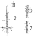
- FIG 1 At the input to the main test pipe 5 (Fig 1) we connected respective input feed lines 11,12,13 for a first food product 1, a second food product 2 and pumpable ice B.
- a three-way valve 7 enabled any of these three substances to be pumped into the test pipe 5 according to choice at a given time.
- the "foods" 1,2 were differently-coloured cornflour-thickened aqueous preparations.
- a collection vessel 6 is indicated at the downstream end of the pipe. It is possible to use detectors to determine characteristic ingredients in compositions passing along the pipe, to monitor flow and in particular the degree of any mixing of different compositions at interfaces. In the present tests a simple visual assessment was enough.
- the transparent pipe was 25 mm in internal diameter.
- a first test (Fig 2) an initial flow of the first food 1 was followed by a brief flow of pumpable ice B to create a buffer region before a subsequent flow of the second food 2.
- the flowable ice plug B moved freely and coherently along the pipe, in full wetting contact with the internal surface, and there was little mingling at the interfaces of the ice plug B with the food columns 1,2.
- the leading end of the ice plug B cleared traces of the first food 1 from the pipe wall almost instantaneously, so that there was no perceivable contamination of the second food 2.
- a food processing plant may be able to send two different products down the same duct successively, very conveniently and without intervening downtime for cleaning.
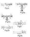
- Fig 4 shows a third test in which the clearing action of the ice plug B left the pipe empty, the plug B being driven by pumping air. Again, the first food 1 was effectively cleared and the pipe wall left clean. There is evidently a cooperative effect of the solid and liquid simultaneously present in the plug B which cleans the pipe surface by a combination of wetting and wiping actions.
- Fig 5 shows a more demanding test where the test pipe 5 branched into two at a T-junction 52.
- the initial flow of first food diverged into two oppositely-directed flows 1'.
- Fig 5b we found that the initial flowable ice plug B divided readily at the junction 52 into two subsidiary plugs B' each following a respective branch of the junction and clearing the respective flow of the first food 1' as effectively as in the single pipe tests.
- pumpable ice can be introduced into the initial pipe in any desired quantity - corresponding to length of the initial plug B - to allow for divided plugs B' of sufficient size after divisions of this kind.
- Fig 6 shows a mixing module 53 included in the test pipe, having a flattened cross-section obstructed by an array of baffles between which fluid flows for mixing.
- Fig 7 shows a cleaning test, in which the internal surface of the otherwise empty test pipe was contaminated over a test section S by smearing with jam 4.
- the pumpable ice is an aqueous preparation containing only a benign solute as freezing point depressant, there is no health/safety problem with feeding it through food processing machinery.
- the food product in the pipe was a fruit yogurt.
- the technical aim was to recover the yogurt from the pipe to the greatest possible extent. We froze a small batch of the yogurt and crushed the resulting frozen yogurt in a blender, as in the preceding experiment. A coherent mass of frozen yogurt particles was readily obtained, and we found that it could be pumped along the pipe, driving the resident liquid yogurt in front of it as readily as did the plain ice. Because the yogurt although essentially aqueous contains substantial quantities of dissolved solids and emulsified fat, the freezing point depressant effect arose naturally so that solid and some melt co-existed readily. The pumped plug of frozen yogurt slush cleared the pipe out effectively. Although the frozen part of the yogurt was of a rather poor quality when thawed, the immediately adjacent part of the column of liquid yogurt maintained its quality perfectly and could be used.
Abstract
Description
- This invention relates to the cleaning or clearing of the interiors of fluid flow conduits, in particular pipes and tubes, and in other aspects to providing a barrier at the end of a body of fluid passing in the conduit, to prevent mixing with another body of fluid in the same conduit. We particularly envisage application of these new techniques in the flow conduits of processing machinery for food products and food components, but the invention also has applications in other fields.
- By way of background, a procedure known as "pigging" is well-established in the fields of oil and gas recovery and distribution. This involves driving a "pig", being a solid body or device shaped to fit the pipeline interior, along the pipe under pressure. The pig may have scrapers or brushes to shift contaminants from the pipeline's interior surface (US-A-5457841 and US-A-5903945); additionally or alternatively it may be adapted to absorb or otherwise take up debris in the pipeline (US-A-4216026). It is known to make a pipeline pig wholly or partly from an elastically deformable material which can pass bends or occasional irregularities such as welding joints in the pipeline without damage, while contacting the pipe surface firmly (see US-A-4389461 and US-A-5924158). It has been proposed to use a solid bullet of ice as a pig, since it will disintegrate spontaneously and harmlessly if it gets stuck. See e.g. US-A-4898197 and US-A-4724007. It has also been proposed to pass a self-sustaining gelled mass, made by gelling a hydrocarbon, along the pipeline e.g. to separate one product flow from another, or to keep the pipe dry when not in use.
- US-A-3057758 describes freezing petroleum in a pipeline in situ, together with injected steam to form a coagulated mass which is solid-like and has the same cross-section as the pipeline.
- Another established use of pigs is in the cleaning of heat exchanger tubes which suffer from the accumulation of internal residues from manufacture or during use: see US-A-4860821.
- In most piping systems however it is normal for cleaning to use direct methods such as brushing and/or flushing using cleaning liquids, which are easier to control and cheaper than pigs. Also, pigs cannot be used where fluid flow conduits are of substantially varying cross-section or include internal obstructions, whereas liquids can.
- In one aspect what we propose is a method of clearing the interior of a fluid flow conduit, so as to clean its interior surface and/or to provide a barrier at the end of a body of fluid passing along the conduit,
characterized by causing a fluid, plastic mass or agglomerate consisting essentially of solid particles cohering by means of a wetting liquid to pass along the conduit in contact with its interior surface. - The wetting liquid is non-gelled. Preferred wetting liquids are aqueous. We also prefer that the wetting liquid wets the conduit interior surface so that the solid particles slide over the surface.
- A second independent aspect, representing also a preferred mode of implementing the first aspect, is to pass a fluid, plastic mass or agglomerate of a mixture of solid particles with a wetting liquid which is, consists essentially of or comprises a melt liquid derived from the solid of the solid particles. Such a mixture may for example conveniently be prepared by comminuting the solid and using it at a temperature near its melting point.
- A particular virtue of these proposals is that a wet, coherent, flowable agglomerate, unlike known deformable or gelled pigs which can generally be made to tolerate only a modest deformation before they break or lose their effectiveness, can provide a truly fluid, plastic and non-tensile entity which is able to exert its effect even where there is substantial change in cross sectional shape and/or size, sharp bending or even branching of the fluid flow conduit. There is usually no need to adapt the pig analogue of the present proposal in any particular way for the given size or shape of conduit involved, provided that the particles are substantially smaller than the conduit. An essentially fluid, divisible mass can easily be fed through conduit cross-sections that no conventional pig could pass.
- Conversely, by contrast with the use of conventional cleaning liquids, we find that a flowable mass of the kind described consisting substantially of cohered solid particles can easily be made to pass along a conduit without disintegrating in the conduit or dispersing into an adjacent liquid. Also the particles can give a fricative cleaning effect on the conduit wall that is not available with a liquid. Preferably the particles are hard and preferably also angular.
- A third independent embodiment of our proposals is to provide a cleaning, clearing, separating or barrier function as described above by passing a mass of comminuted ice along the conduit. Such an ice pig has many advantages. We find that it is sufficiently flowable, plastic and divisible to pass readily through many shapes and sizes of conduit interior. It is typically sufficiently coherent - by virtue of its own meltwater - that it does not disintegrate or disperse in the conduit.
- Furthermore, ice is easily prepared, economical and safe. Accordingly, it becomes practical to apply the present techniques in the flow conduits of food processing machinery.
- Conventionally, in food processing plants material has to be removed from the duct work or piping every time the plant needs cleaning and when the product line is changed. Removing food material from ducts is expensive, slow and usually wasteful because it is difficult to prevent back-mixing or diffusion of the food material into the cleaning fluid or into the subsequent product line, as the case may be. All of these difficulties lead to increased cost.
- By contrast, even when a food material does get mixed with ice it is often not entirely spoiled but can be used e.g. for animal feed.
- In our work we have found that slush ice or comminuted ice is readily preparable in a form suitable for passing through piping, including bends, junctions and cross-sectional changes such as orifice plates and mixing sections.
- Because the simultaneous presence of water and ice gives best results, we prefer to include a freezing point depressant in the water used to make the ice. This increases the range of temperature over which coexistent ice and water can persist. Simple non-toxic compounds such as sugar and salt can be used.
- The use of a mass of frozen particles wetted by the corresponding melt liquid is not confined to ordinary ice, with or without freezing point depressant. For example in chemical and biochemical processing, crushes of frozen organic solvents can be used. An example is peracetic acid, which freezes readily, is highly active against biocontaminants and breaks down to harmless compounds in due course, in contrast with the chlorine-containing bleaches conventionally used.
- A further particular aspect of our proposal is in the context of an overall process or situation in which a process liquid in the nature of a mixture and/or solution is present in or passes along a fluid conduit. We propose to carry out any of the cleaning, clearing or barrier operations as proposed herein in that conduit, using for the fluid agglomerate a frozen material which either is the native process liquid, frozen and broken into particles, or is compatible with it in the sense of being substantially or entirely free of ingredients which are not ingredients of the process liquid. Such a procedure can be especially congenial in that any melting or mixing of the agglomerate body with adjacent process liquid in the conduit does not significantly contaminate it. Since many process liquids consist of or comprise solutions, the freezing point depressant function is then intrinsic to the native material which is therefore inherently suitable for freezing and crushing to provide an effective cohering agglomerate body.
- Certain practical aspects of the methods disclosed herein can readily be determined by a skilled person on the basis of the technical context and technical purpose.
- Thus particle size for example is not usually critical in the agglomerate, provided that the largest particle can pass all the way through the relevant conduit system. In practice, using crushed frozen material, there will be a wide range of particle sizes. Purely by way of illustration, in crushed ice suitable for use in food processing machinery - whose pipe dimensions range down from about 100mm through about 25mm (conventional) to about 10mm in smaller branches - ice particles up to about 5mm will be acceptable and effective.
- The proportion of solid and liquid in the agglomerate mass is also not critical provided that the mass coheres sufficiently to move as a body along the relevant conduit under the relevant conditions. Typically the solids content would be at least 30% by weight, however.
- The speed at which the agglomerate mass is driven through the conduit may vary largely according to the situation. Anything from 0.05 to 5 m/s might be appropriate, for example.
- Particular embodiments of our proposals involve pumping the fluid mass (agglomerate) along a fluid flow conduit having one or more of
- substantial changes in cross-sectional area e.g. greater than 20%;
- internal obstructions, such as probes or sensors, projecting into the conduit space;
- branching or merging of conduits.
- In particular embodiments of the procedure the mentioned fluid mass may be used for any one or more of:
- driving a body of fluid material in front of it along the conduit;
- more generally, forming a barrier between a first, downstream body of fluid material in the conduit and a second, upstream body e.g. of a different fluid material, or an empty section of conduit;
- cleaning the interior surface of the conduit.
- Usually the present agglomerate is a longitudinally-localised body in the conduit e.g. not more than 20 times as long as it is wide.
- These procedures may be carried out in food processing plant. Other areas of industrial application include hydrocarbon recovery in the oil industry, petrochemical processing and fine chemicals e.g. dyes and pharmaceuticals. With fine chemicals there is an advantage in the ability to clear a conduit with a smaller mass of cleaning material (e.g. ice, or other frozen solvent) than when using liquid cleaning. This aids economical recovery of high-value residues. Decontamination of conduit surfaces in general is a relevant field. Where there are toxic or otherwise dangerous residues there is again an advantage in relatively low-volume recovery.
- Modes of application of the invention are now described by way of example, with reference to the accompanying drawings illustrating practical procedures and tests and in which
- Fig 1 shows introduction of various media into a test pipe;
- Fig 2 shows separation of one food from another in a test pipe;
- Fig 3 shows a change of pipe cross-section;
- Fig 4 shows clearing out a pipe;
- Figs 5a, b show stages of flow of two separated fluids through a branching pipe;
- Fig 6 shows flow through a mixer module, and
- Fig 7a, b shows stages of cleaning a pipe.
- Preparation of pumpable ice was by dissolving sugar or salt in water, as a freezing point depressant, followed by freezing and crushing in a blender.
- As is known, the freezing point depressant has the effect of stabilizing the co-existence of ice and melt water as a flowable preparation over a range of temperatures, because the dissolved freezing point depressant concentrates in the melt as freezing proceeds; the freezing point of the melt tends therefore to rise or fall in correspondence with rises and falls in the ambient temperature.
- We found the resulting ice/water mixture or slush to be readily flowable and in particular it could be pumped through pipes using conventional pump pressures.
- To test the effectiveness of this flowable ice in clearing, cleaning or separating food materials in pipes of food processing plant, we prepared laboratory test apparatus having transparent pipes so that the behaviour of the fluids could easily be observed.
- At the input to the main test pipe 5 (Fig 1) we connected respective
input feed lines second food product 2 and pumpable ice B. A three-way valve 7 enabled any of these three substances to be pumped into thetest pipe 5 according to choice at a given time. For easy visual assessment the "foods" 1,2 were differently-coloured cornflour-thickened aqueous preparations. - A collection vessel 6 is indicated at the downstream end of the pipe. It is possible to use detectors to determine characteristic ingredients in compositions passing along the pipe, to monitor flow and in particular the degree of any mixing of different compositions at interfaces. In the present tests a simple visual assessment was enough. The transparent pipe was 25 mm in internal diameter.
- In a first test (Fig 2) an initial flow of the first food 1 was followed by a brief flow of pumpable ice B to create a buffer region before a subsequent flow of the
second food 2. We noted that the flowable ice plug B moved freely and coherently along the pipe, in full wetting contact with the internal surface, and there was little mingling at the interfaces of the ice plug B with thefood columns 1,2. The leading end of the ice plug B cleared traces of the first food 1 from the pipe wall almost instantaneously, so that there was no perceivable contamination of thesecond food 2. - It will be appreciated that, in this way, a food processing plant may be able to send two different products down the same duct successively, very conveniently and without intervening downtime for cleaning.
- In a second test an
orifice plate 51 of internal diameter 10 mm was put in the test pipe. It was found that the crushed ice plug B flowed readily through the orifice and re-occupied the duct cross-section on the downstream side promptly, so that there was no residue of the first food 1 behind the orifice plate after the ice plug B had passed. - Fig 4 shows a third test in which the clearing action of the ice plug B left the pipe empty, the plug B being driven by pumping air. Again, the first food 1 was effectively cleared and the pipe wall left clean. There is evidently a cooperative effect of the solid and liquid simultaneously present in the plug B which cleans the pipe surface by a combination of wetting and wiping actions.
- Fig 5 shows a more demanding test where the
test pipe 5 branched into two at a T-junction 52. The initial flow of first food diverged into two oppositely-directed flows 1'. As shown in Fig 5b, we found that the initial flowable ice plug B divided readily at thejunction 52 into two subsidiary plugs B' each following a respective branch of the junction and clearing the respective flow of the first food 1' as effectively as in the single pipe tests. It will be appreciated that pumpable ice can be introduced into the initial pipe in any desired quantity - corresponding to length of the initial plug B - to allow for divided plugs B' of sufficient size after divisions of this kind. - Fig 6 shows a
mixing module 53 included in the test pipe, having a flattened cross-section obstructed by an array of baffles between which fluid flows for mixing. As with the orifice plate, we found that the pumpable ice readily followed the intricacy of this system with sufficient wetting and wiping to clear the first food composition from it entirely. - Fig 7 shows a cleaning test, in which the internal surface of the otherwise empty test pipe was contaminated over a test section S by smearing with jam 4. By driving the pumpable ice preparation B along the pipe through the test section, we found that the adherent jam was completely cleared from the pipe; there was no visible residue.
- A further good property noted was the remarkable temperature tolerance of the procedure, despite the use of ice in a system well above its melting point. We found that even in warm pipes the technique was effective. This is attributable to the poor thermal conductivity of ice, coupled with the ability of the shape of the mass to self-adjust under pumping pressure to continue filling the pipe despite surface melt losses.
- Since the pumpable ice is an aqueous preparation containing only a benign solute as freezing point depressant, there is no health/safety problem with feeding it through food processing machinery.
- In a further example the food product in the pipe was a fruit yogurt. The technical aim was to recover the yogurt from the pipe to the greatest possible extent. We froze a small batch of the yogurt and crushed the resulting frozen yogurt in a blender, as in the preceding experiment. A coherent mass of frozen yogurt particles was readily obtained, and we found that it could be pumped along the pipe, driving the resident liquid yogurt in front of it as readily as did the plain ice. Because the yogurt although essentially aqueous contains substantial quantities of dissolved solids and emulsified fat, the freezing point depressant effect arose naturally so that solid and some melt co-existed readily. The pumped plug of frozen yogurt slush cleared the pipe out effectively. Although the frozen part of the yogurt was of a rather poor quality when thawed, the immediately adjacent part of the column of liquid yogurt maintained its quality perfectly and could be used.
Claims (16)
- A method of clearing or clearing the interior of a fluid flow conduit (5), or providing a movable plug in a fluid flow conduit (5), by causing a body (B) which spans the conduit interior to pass along inside the conduit, characterised in that the body (B) is a flowable agglomerate mass consisting essentially of hard solid frozen particles and a non-gelled wetting liquid, which comprises a melt derived from the frozen particles and by means of which the particles cohere.
- A method according to claim 1 wherein the particles and wetting liquid are aqueous.
- A method according to claim 2 in which the particles are ice particles.
- A method according to claim 3, in which the ice particles a have a particle size of up to 5mm.
- A method according to claim 1 in which the particles are a frozen organic solvent.
- A method according to claim 1 or 2 in which the particles are a frozen liquid food or drink, or frozen liquid ingredient of a food or drink.
- A method according to any one of the preceding claims in which the wetting liquid contains a freezing point depressant.
- A method according to claim 7 in which the freezing point depressant is salt or sugar.
- A method according to any one of the preceding claims, wherein the wetting liquid wets the conduit interior surface.
- A method according to any one of the preceding claims, wherein the agglomerate mass comprises at least 30% by weight solid particles.
- A method according to any one of the preceding claims in which the body (B) is caused to pass along the conduit (5) as a barrier at one end of a body of other flowable material in the conduit, or between two bodies of other flowable material in the conduit.
- A method according to claim 8 in which the body (B) is used to drive a said body of flowable material along the conduit for recovery.
- A method according to any one of the preceding claims in which a process liquid is present in the conduit, and such process liquid is frozen and comminuted to provide the mass of particles to form the body (B) for passage in the conduit in contact with the process liquid.
- A method according to any one of the preceding claims in which the fluid flow conduit has any one or more of the following features:- greater than 20% change in cross-sectional area;- internal local obstructions projecting into the conduit space;- branching or merging of conduits, and the body (B) negotiates said feature(s).
- A method according to any one of the preceding claims, wherein the agglomerate mass is driven along the conduit at 0.05 m/s to 5 m/s.
- A method according to any one of the preceding claims, wherein the agglomerate mass is not more than twenty times as long as it is wide.
Applications Claiming Priority (3)
| Application Number | Priority Date | Filing Date | Title |
|---|---|---|---|
| GB0000560 | 2000-01-11 | ||
| GBGB0000560.3A GB0000560D0 (en) | 2000-01-11 | 2000-01-11 | Cleaning and fluid separation in fluid flow conduits |
| PCT/GB2001/000093 WO2001051224A1 (en) | 2000-01-11 | 2001-01-10 | Cleaning and separation in conduits |
Publications (2)
| Publication Number | Publication Date |
|---|---|
| EP1248689A1 EP1248689A1 (en) | 2002-10-16 |
| EP1248689B1 true EP1248689B1 (en) | 2006-04-05 |
Family
ID=9883497
Family Applications (1)
| Application Number | Title | Priority Date | Filing Date |
|---|---|---|---|
| EP01900502A Expired - Lifetime EP1248689B1 (en) | 2000-01-11 | 2001-01-10 | Cleaning and separation in conduits |
Country Status (10)
| Country | Link |
|---|---|
| US (1) | US6916383B2 (en) |
| EP (1) | EP1248689B1 (en) |
| JP (1) | JP4653921B2 (en) |
| KR (1) | KR100786148B1 (en) |
| AT (1) | ATE322353T1 (en) |
| AU (1) | AU2001225330A1 (en) |
| DE (1) | DE60118524T2 (en) |
| ES (1) | ES2263580T3 (en) |
| GB (1) | GB0000560D0 (en) |
| WO (1) | WO2001051224A1 (en) |
Families Citing this family (27)
| Publication number | Priority date | Publication date | Assignee | Title |
|---|---|---|---|---|
| GB0000560D0 (en) * | 2000-01-11 | 2000-03-01 | Univ Bristol | Cleaning and fluid separation in fluid flow conduits |
| GB0116826D0 (en) * | 2001-07-10 | 2001-08-29 | British Nuclear Fuels Ltd | |
| WO2004000475A1 (en) * | 2002-06-20 | 2003-12-31 | University Of Bristol | Methods of cleaning, clearing and separation in conduits |
| JP2004340433A (en) * | 2003-05-14 | 2004-12-02 | Tokai Engineering Co Ltd | Method of washing inside of heat exchanger coil |
| US20070193610A1 (en) * | 2004-03-31 | 2007-08-23 | Ecolab Inc. | System For Semi-Automatic Line Cleaning |
| US7311224B2 (en) * | 2004-11-09 | 2007-12-25 | Ecolab Inc. | Chemical dispense system for cleaning components of a fluid dispensing system |
| US20060097003A1 (en) * | 2004-11-09 | 2006-05-11 | Joerg Emmendoerfer | Chemical dispense system for cleaning components of a fluid dispensing system |
| US20060169715A1 (en) * | 2004-11-09 | 2006-08-03 | Jorg Emmendorfer | Controller-based management of a fluid dispensing system |
| US20060175352A1 (en) * | 2004-11-09 | 2006-08-10 | Jorg Emmendorfer | Cleaning processes for a fluid dispensing system |
| US20060113322A1 (en) * | 2004-11-09 | 2006-06-01 | Maser Bryan A | Monitoring operation of a fluid dispensing system |
| US20070095859A1 (en) * | 2005-10-31 | 2007-05-03 | Maser Bryan A | Controller-based management of a fluid dispensing system |
| JP2014083513A (en) * | 2012-10-25 | 2014-05-12 | Hiroshi Suzuki | Method and system for cleaning pipeline |
| JP6097525B2 (en) * | 2012-10-31 | 2017-03-15 | 吉佳エンジニアリング株式会社 | Pipe cleaning method and pipe cleaning system |
| JP6049406B2 (en) * | 2012-11-08 | 2016-12-21 | 鈴木 宏 | Cleaning method and cleaning system for the Fushie pipeline |
| JP6140431B2 (en) * | 2012-11-21 | 2017-05-31 | 鈴木 宏 | Method for manufacturing a sherbet body for cleaning the inside of a pipeline |
| JP6310184B2 (en) * | 2013-03-29 | 2018-04-11 | 鈴木 宏 | Cleaning pipeline survey method |
| JP6489762B2 (en) * | 2013-06-05 | 2019-03-27 | 鈴木 宏 | Pipe cleaning method and pipe cleaning system |
| GB2521826B (en) * | 2013-12-18 | 2017-11-08 | Ge Oil & Gas Uk Ltd | Multiple chemical supply line |
| US9636721B2 (en) | 2014-04-16 | 2017-05-02 | Quickdraft, Inc. | Method and clean-in-place system for conveying tubes |
| US9731334B2 (en) | 2014-07-01 | 2017-08-15 | Kirt Ervin | Microbot pigging system |
| WO2018146268A1 (en) | 2017-02-10 | 2018-08-16 | Suez Groupe | Method and apparatus for cleaning and disinfection of conduits |
| CN107806137A (en) * | 2017-10-13 | 2018-03-16 | 中国石油大学(北京) | Sewer dredger and method |
| WO2019113635A1 (en) * | 2017-12-11 | 2019-06-20 | Saban Ventures Pty Limited | Suspension cleaning |
| CN113454003A (en) * | 2019-02-18 | 2021-09-28 | 热带产品公司 | Method for minimizing material mixing during transitions in a material processing system |
| EP3848130B1 (en) * | 2020-01-13 | 2023-08-02 | Fraunhofer-Gesellschaft zur Förderung der angewandten Forschung e.V. | Method and device for cleaning a tubular cavity by means of a passive, contour-adaptive pig |
| CN113426779B (en) * | 2021-06-29 | 2023-02-03 | 邦凯控股集团有限公司 | Melt pipeline cleaning device |
| KR102567824B1 (en) | 2021-10-28 | 2023-08-18 | (주)보선워터텍 | Pipeline cleaning system |
Family Cites Families (23)
| Publication number | Priority date | Publication date | Assignee | Title |
|---|---|---|---|---|
| US3057758A (en) * | 1960-10-26 | 1962-10-09 | Harry H Walker | System for measuring and increasing flow through pipelines |
| US3085916A (en) * | 1961-10-16 | 1963-04-16 | Zimmie | Method of removing and preventing accumulation in cooling systems |
| US3676091A (en) * | 1970-09-08 | 1972-07-11 | Shell Oil Co | Method for forming and circulating plugs in a pipeline |
| US4220012A (en) | 1976-09-13 | 1980-09-02 | Brister Beryle D | Apparatus for freezing a slug of liquid in a section of a large diameter fluid transmission line |
| US4383783A (en) | 1978-09-18 | 1983-05-17 | Shell Oil Company | Pipeline gel plug |
| US4216026A (en) | 1979-02-05 | 1980-08-05 | Shell Oil Company | System for removing fluid and debris from pipelines |
| US4473408A (en) | 1982-01-12 | 1984-09-25 | The Dow Chemical Company | Cleaning pipeline interior with gelled pig |
| JPS58156385A (en) * | 1982-03-15 | 1983-09-17 | 株式会社ホクカン | Method of washing and cleaning water conduit, etc. |
| US4898197A (en) * | 1983-03-11 | 1990-02-06 | Lacress Nominees Pty. Ltd. | Cleaning of tubes using projectiles |
| SU1141153A1 (en) | 1983-09-27 | 1985-02-23 | Университет дружбы народов им.Патриса Лумумбы | Method of cleaning drains from silt deposits |
| GB8505429D0 (en) * | 1985-03-02 | 1985-04-03 | Kue Eng Ltd | Blast cleaning |
| JPS6211586A (en) * | 1985-07-08 | 1987-01-20 | 日本鉱業株式会社 | Method of removing attachment in tube and polishing and cleaning material for attachment in tube |
| JPS6438184A (en) * | 1987-08-01 | 1989-02-08 | Shizuo Sagawa | Method of cleaning pipe |
| SU1625886A1 (en) | 1987-12-28 | 1991-02-07 | Институт Геологии И Геохимии Горючих Ископаемых Ан Усср | Composition of polymeric cleaning plug for deparaffination of oil pipelines during long-term operation |
| JPH0368484A (en) * | 1989-08-08 | 1991-03-25 | Shinji Hasegawa | Method for cleaning drainpipe |
| JP2833835B2 (en) * | 1990-07-17 | 1998-12-09 | 大成建設株式会社 | Pipe cleaning device |
| DE4131208A1 (en) * | 1991-09-19 | 1993-03-25 | Dirk Pitzel | METHOD AND DEVICE FOR CONVEYING A LIQUID AND ANOTHER FLOWABLE MEDIUM THROUGH THE SAME CONVEYOR |
| JPH05261349A (en) * | 1992-03-17 | 1993-10-12 | Innov Center Kk | Method and apparatus for washing interior of pipe |
| US5300152A (en) | 1992-07-27 | 1994-04-05 | Atlantic Richfield Company | Method of cleaning tubular with frozen layered gelatin pig |
| US6041811A (en) | 1997-09-04 | 2000-03-28 | Pa-Plug, Inc. | Plug for forming an ice barrier in a pipeline |
| US6485577B1 (en) | 2000-01-07 | 2002-11-26 | Robert Kiholm | Pipe pig formed of frozen product |
| GB0000560D0 (en) * | 2000-01-11 | 2000-03-01 | Univ Bristol | Cleaning and fluid separation in fluid flow conduits |
| GB0116826D0 (en) * | 2001-07-10 | 2001-08-29 | British Nuclear Fuels Ltd |
-
2000
- 2000-01-11 GB GBGB0000560.3A patent/GB0000560D0/en not_active Ceased
-
2001
- 2001-01-10 AU AU2001225330A patent/AU2001225330A1/en not_active Abandoned
- 2001-01-10 AT AT01900502T patent/ATE322353T1/en active
- 2001-01-10 EP EP01900502A patent/EP1248689B1/en not_active Expired - Lifetime
- 2001-01-10 ES ES01900502T patent/ES2263580T3/en not_active Expired - Lifetime
- 2001-01-10 WO PCT/GB2001/000093 patent/WO2001051224A1/en active IP Right Grant
- 2001-01-10 JP JP2001551632A patent/JP4653921B2/en not_active Expired - Lifetime
- 2001-01-10 KR KR1020027008857A patent/KR100786148B1/en active IP Right Grant
- 2001-01-10 US US10/169,709 patent/US6916383B2/en not_active Expired - Lifetime
- 2001-01-10 DE DE60118524T patent/DE60118524T2/en not_active Expired - Lifetime
Also Published As
| Publication number | Publication date |
|---|---|
| ATE322353T1 (en) | 2006-04-15 |
| WO2001051224A1 (en) | 2001-07-19 |
| KR20020079774A (en) | 2002-10-19 |
| ES2263580T3 (en) | 2006-12-16 |
| JP4653921B2 (en) | 2011-03-16 |
| AU2001225330A1 (en) | 2001-07-24 |
| EP1248689A1 (en) | 2002-10-16 |
| JP2003519571A (en) | 2003-06-24 |
| DE60118524T2 (en) | 2006-11-23 |
| KR100786148B1 (en) | 2007-12-21 |
| GB0000560D0 (en) | 2000-03-01 |
| US20030140944A1 (en) | 2003-07-31 |
| DE60118524D1 (en) | 2006-05-18 |
| US6916383B2 (en) | 2005-07-12 |
Similar Documents
| Publication | Publication Date | Title |
|---|---|---|
| EP1248689B1 (en) | Cleaning and separation in conduits | |
| Quarini et al. | A review of fluid-driven pipeline pigs and their applications | |
| US8719989B1 (en) | Chemical pigging apparatus for pipelines | |
| US4860821A (en) | Process for cleaning tube type heat exchangers | |
| Moerman et al. | Cleaning in place (CIP) in food processing | |
| WO2017198684A1 (en) | Method of removing deposits from an inside surface of a conduit | |
| GB2358229A (en) | Cleaning and separation in fluid flow conduits | |
| JP2019025372A (en) | Pipeline cleaning method and pipeline cleaning system | |
| WO2004000475A1 (en) | Methods of cleaning, clearing and separation in conduits | |
| US3659305A (en) | Flexible pipeline pigs | |
| EP1404464B1 (en) | Decontamination of pipework | |
| Ainslie et al. | Heat exchanger cleaning using ice pigging | |
| CA2197014C (en) | Module for cleaning conduits | |
| US9295956B2 (en) | Refrigerated agitator assembly for mixers | |
| Prasad et al. | ICE PIGGING IS AN EMERGING METHOD OF CLEANING-IN-PLACE INDAIRY AND FOOD PROCESS INDUSTRIES | |
| RU2424071C1 (en) | Method and device for cleaning inner surface of closed complex structures | |
| Khalid et al. | Removal kinetics of pink guava puree fouling deposit from a stainless steel surface during alkaline cycle | |
| JP2002307032A (en) | Method and apparatus for pig system | |
| RU2420361C2 (en) | Method of cleaning tubes of sediments, system to this end, working medium and device to feed working media into tubes to be cleaned | |
| US8268084B2 (en) | Liquid injection into gas stream | |
| Stoltze | A new pipeline cleaning technology: Hydraulically Activated Power Pigging (HAPPTM) | |
| Landes | Pipeline pigging'- an important tail | |
| Cheow et al. | Circulation cleaning of a plate heat exchanger fouled by tomato juice: II. Cleaning with caustic soda solution | |
| JP2016077993A (en) | Cleaning device and cleaning method for oil tank | |
| BREMER et al. | Clean-in-place |
Legal Events
| Date | Code | Title | Description |
|---|---|---|---|
| PUAI | Public reference made under article 153(3) epc to a published international application that has entered the european phase |
Free format text: ORIGINAL CODE: 0009012 |
|
| 17P | Request for examination filed |
Effective date: 20020801 |
|
| AK | Designated contracting states |
Kind code of ref document: A1 Designated state(s): AT BE CH CY DE DK ES FI FR GB GR IE IT LI LU MC NL PT SE TR |
|
| AX | Request for extension of the european patent |
Free format text: AL;LT;LV;MK;RO;SI |
|
| 17Q | First examination report despatched |
Effective date: 20040407 |
|
| GRAP | Despatch of communication of intention to grant a patent |
Free format text: ORIGINAL CODE: EPIDOSNIGR1 |
|
| GRAS | Grant fee paid |
Free format text: ORIGINAL CODE: EPIDOSNIGR3 |
|
| GRAA | (expected) grant |
Free format text: ORIGINAL CODE: 0009210 |
|
| AK | Designated contracting states |
Kind code of ref document: B1 Designated state(s): AT BE CH CY DE DK ES FI FR GB GR IE IT LI LU MC NL PT SE TR |
|
| PG25 | Lapsed in a contracting state [announced via postgrant information from national office to epo] |
Ref country code: IT Free format text: LAPSE BECAUSE OF FAILURE TO SUBMIT A TRANSLATION OF THE DESCRIPTION OR TO PAY THE FEE WITHIN THE PRESCRIBED TIME-LIMIT;WARNING: LAPSES OF ITALIAN PATENTS WITH EFFECTIVE DATE BEFORE 2007 MAY HAVE OCCURRED AT ANY TIME BEFORE 2007. THE CORRECT EFFECTIVE DATE MAY BE DIFFERENT FROM THE ONE RECORDED. Effective date: 20060405 Ref country code: NL Free format text: LAPSE BECAUSE OF FAILURE TO SUBMIT A TRANSLATION OF THE DESCRIPTION OR TO PAY THE FEE WITHIN THE PRESCRIBED TIME-LIMIT Effective date: 20060405 Ref country code: FI Free format text: LAPSE BECAUSE OF FAILURE TO SUBMIT A TRANSLATION OF THE DESCRIPTION OR TO PAY THE FEE WITHIN THE PRESCRIBED TIME-LIMIT Effective date: 20060405 |
|
| REG | Reference to a national code |
Ref country code: GB Ref legal event code: FG4D |
|
| REG | Reference to a national code |
Ref country code: CH Ref legal event code: EP |
|
| REG | Reference to a national code |
Ref country code: IE Ref legal event code: FG4D |
|
| REF | Corresponds to: |
Ref document number: 60118524 Country of ref document: DE Date of ref document: 20060518 Kind code of ref document: P |
|
| PG25 | Lapsed in a contracting state [announced via postgrant information from national office to epo] |
Ref country code: DK Free format text: LAPSE BECAUSE OF FAILURE TO SUBMIT A TRANSLATION OF THE DESCRIPTION OR TO PAY THE FEE WITHIN THE PRESCRIBED TIME-LIMIT Effective date: 20060705 |
|
| REG | Reference to a national code |
Ref country code: SE Ref legal event code: TRGR |
|
| PG25 | Lapsed in a contracting state [announced via postgrant information from national office to epo] |
Ref country code: PT Free format text: LAPSE BECAUSE OF FAILURE TO SUBMIT A TRANSLATION OF THE DESCRIPTION OR TO PAY THE FEE WITHIN THE PRESCRIBED TIME-LIMIT Effective date: 20060905 |
|
| NLV1 | Nl: lapsed or annulled due to failure to fulfill the requirements of art. 29p and 29m of the patents act | ||
| ET | Fr: translation filed | ||
| REG | Reference to a national code |
Ref country code: ES Ref legal event code: FG2A Ref document number: 2263580 Country of ref document: ES Kind code of ref document: T3 |
|
| PG25 | Lapsed in a contracting state [announced via postgrant information from national office to epo] |
Ref country code: MC Free format text: LAPSE BECAUSE OF NON-PAYMENT OF DUE FEES Effective date: 20070131 |
|
| PLBE | No opposition filed within time limit |
Free format text: ORIGINAL CODE: 0009261 |
|
| STAA | Information on the status of an ep patent application or granted ep patent |
Free format text: STATUS: NO OPPOSITION FILED WITHIN TIME LIMIT |
|
| 26N | No opposition filed |
Effective date: 20070108 |
|
| PG25 | Lapsed in a contracting state [announced via postgrant information from national office to epo] |
Ref country code: GR Free format text: LAPSE BECAUSE OF FAILURE TO SUBMIT A TRANSLATION OF THE DESCRIPTION OR TO PAY THE FEE WITHIN THE PRESCRIBED TIME-LIMIT Effective date: 20060706 |
|
| PG25 | Lapsed in a contracting state [announced via postgrant information from national office to epo] |
Ref country code: LU Free format text: LAPSE BECAUSE OF NON-PAYMENT OF DUE FEES Effective date: 20070110 Ref country code: CY Free format text: LAPSE BECAUSE OF FAILURE TO SUBMIT A TRANSLATION OF THE DESCRIPTION OR TO PAY THE FEE WITHIN THE PRESCRIBED TIME-LIMIT Effective date: 20060405 |
|
| PG25 | Lapsed in a contracting state [announced via postgrant information from national office to epo] |
Ref country code: TR Free format text: LAPSE BECAUSE OF FAILURE TO SUBMIT A TRANSLATION OF THE DESCRIPTION OR TO PAY THE FEE WITHIN THE PRESCRIBED TIME-LIMIT Effective date: 20060405 |
|
| REG | Reference to a national code |
Ref country code: CH Ref legal event code: PUE Owner name: AQUALOGY ENVIRONMENT LIMITED, GB Free format text: FORMER OWNER: PCIP LIMITED, GB Ref country code: CH Ref legal event code: PUE Owner name: PCIP LIMITED, GB Free format text: FORMER OWNER: UNIVERSITY OF BRISTOL, GB Ref country code: CH Ref legal event code: PCOW Free format text: NEW ADDRESS: 290 AZTEC WEST ALMONDSBURY, BRISTOL BS32 4SY (GB) Ref country code: CH Ref legal event code: PCOW Free format text: NEW ADDRESS: 160 AZTEC WEST, ALMONDSBURY,, BRISTOL BS32 4TU (GB) |
|
| REG | Reference to a national code |
Ref country code: GB Ref legal event code: 732E Free format text: REGISTERED BETWEEN 20151022 AND 20151028 |
|
| REG | Reference to a national code |
Ref country code: DE Ref legal event code: R082 Ref document number: 60118524 Country of ref document: DE Representative=s name: LEINWEBER & ZIMMERMANN, DE Ref country code: DE Ref legal event code: R081 Ref document number: 60118524 Country of ref document: DE Owner name: AQUALOGY ENVIRONMENT LIMITED, ALMONDSBURY, GB Free format text: FORMER OWNER: UNIVERSITY OF BRISTOL, CLIFTON, BRISTOL, GB Ref country code: DE Ref legal event code: R081 Ref document number: 60118524 Country of ref document: DE Owner name: SUEZ ADVANCED SOLUTIONS UK LTD., GB Free format text: FORMER OWNER: UNIVERSITY OF BRISTOL, CLIFTON, BRISTOL, GB |
|
| REG | Reference to a national code |
Ref country code: FR Ref legal event code: PLFP Year of fee payment: 16 |
|
| REG | Reference to a national code |
Ref country code: ES Ref legal event code: PC2A Owner name: AQUALOGY ENVIRONMENT LIMITED Effective date: 20160118 |
|
| REG | Reference to a national code |
Ref country code: FR Ref legal event code: CA Effective date: 20160120 Ref country code: FR Ref legal event code: TP Owner name: AQUALOGY ENVIRONMENT LIMITED, GB Effective date: 20160120 |
|
| REG | Reference to a national code |
Ref country code: FR Ref legal event code: CA Effective date: 20160128 |
|
| REG | Reference to a national code |
Ref country code: DE Ref legal event code: R082 Ref document number: 60118524 Country of ref document: DE Representative=s name: LEINWEBER & ZIMMERMANN PATENTANWALTS-PARTG MBB, DE Ref country code: DE Ref legal event code: R082 Ref document number: 60118524 Country of ref document: DE Representative=s name: LEINWEBER & ZIMMERMANN, DE Ref country code: DE Ref legal event code: R081 Ref document number: 60118524 Country of ref document: DE Owner name: SUEZ ADVANCED SOLUTIONS UK LTD., GB Free format text: FORMER OWNER: AQUALOGY ENVIRONMENT LIMITED, ALMONDSBURY, BRISTOL, GB |
|
| REG | Reference to a national code |
Ref country code: CH Ref legal event code: PFA Owner name: SUEZ ADVANCED SOLUTIONS UK LIMITED, GB Free format text: FORMER OWNER: AQUALOGY ENVIRONMENT LIMITED, GB |
|
| REG | Reference to a national code |
Ref country code: FR Ref legal event code: CA Effective date: 20160629 Ref country code: FR Ref legal event code: CD Owner name: SUEZ ADVANCED SOLUTIONS UK LIMITED, GB Effective date: 20160629 |
|
| REG | Reference to a national code |
Ref country code: ES Ref legal event code: PC2A Owner name: SUEZ ADVANCED SOLUTIONS UK LIMITED Effective date: 20160805 |
|
| REG | Reference to a national code |
Ref country code: FR Ref legal event code: PLFP Year of fee payment: 17 |
|
| REG | Reference to a national code |
Ref country code: AT Ref legal event code: PC Ref document number: 322353 Country of ref document: AT Kind code of ref document: T Owner name: SUEZ ADVANCED SOLUTIONS UK LIMITED, GB Effective date: 20161220 |
|
| REG | Reference to a national code |
Ref country code: FR Ref legal event code: PLFP Year of fee payment: 18 |
|
| PGFP | Annual fee paid to national office [announced via postgrant information from national office to epo] |
Ref country code: IE Payment date: 20200127 Year of fee payment: 20 Ref country code: AT Payment date: 20191219 Year of fee payment: 20 Ref country code: ES Payment date: 20200205 Year of fee payment: 20 Ref country code: DE Payment date: 20200129 Year of fee payment: 20 Ref country code: SE Payment date: 20200129 Year of fee payment: 20 Ref country code: IT Payment date: 20200123 Year of fee payment: 20 Ref country code: GB Payment date: 20200127 Year of fee payment: 20 |
|
| PGFP | Annual fee paid to national office [announced via postgrant information from national office to epo] |
Ref country code: CH Payment date: 20200131 Year of fee payment: 20 Ref country code: BE Payment date: 20200127 Year of fee payment: 20 |
|
| PGFP | Annual fee paid to national office [announced via postgrant information from national office to epo] |
Ref country code: FR Payment date: 20200127 Year of fee payment: 20 |
|
| REG | Reference to a national code |
Ref country code: DE Ref legal event code: R071 Ref document number: 60118524 Country of ref document: DE |
|
| REG | Reference to a national code |
Ref country code: CH Ref legal event code: PL |
|
| REG | Reference to a national code |
Ref country code: GB Ref legal event code: PE20 Expiry date: 20210109 |
|
| REG | Reference to a national code |
Ref country code: AT Ref legal event code: MK07 Ref document number: 322353 Country of ref document: AT Kind code of ref document: T Effective date: 20210110 |
|
| REG | Reference to a national code |
Ref country code: SE Ref legal event code: EUG |
|
| REG | Reference to a national code |
Ref country code: IE Ref legal event code: MK9A |
|
| REG | Reference to a national code |
Ref country code: BE Ref legal event code: MK Effective date: 20210110 |
|
| PG25 | Lapsed in a contracting state [announced via postgrant information from national office to epo] |
Ref country code: GB Free format text: LAPSE BECAUSE OF EXPIRATION OF PROTECTION Effective date: 20210109 Ref country code: IE Free format text: LAPSE BECAUSE OF EXPIRATION OF PROTECTION Effective date: 20210110 |
|
| REG | Reference to a national code |
Ref country code: ES Ref legal event code: FD2A Effective date: 20220128 |
|
| PG25 | Lapsed in a contracting state [announced via postgrant information from national office to epo] |
Ref country code: ES Free format text: LAPSE BECAUSE OF EXPIRATION OF PROTECTION Effective date: 20210111 |