EP1248488B1 - Verfahren zur Bestimmung des Zustands eines Kommunikationsendgerät - Google Patents
Verfahren zur Bestimmung des Zustands eines Kommunikationsendgerät Download PDFInfo
- Publication number
- EP1248488B1 EP1248488B1 EP02364016A EP02364016A EP1248488B1 EP 1248488 B1 EP1248488 B1 EP 1248488B1 EP 02364016 A EP02364016 A EP 02364016A EP 02364016 A EP02364016 A EP 02364016A EP 1248488 B1 EP1248488 B1 EP 1248488B1
- Authority
- EP
- European Patent Office
- Prior art keywords
- terminal
- activity status
- management method
- server
- information
- Prior art date
- Legal status (The legal status is an assumption and is not a legal conclusion. Google has not performed a legal analysis and makes no representation as to the accuracy of the status listed.)
- Expired - Lifetime
Links
Images

Classifications
-
- H—ELECTRICITY
- H04—ELECTRIC COMMUNICATION TECHNIQUE
- H04L—TRANSMISSION OF DIGITAL INFORMATION, e.g. TELEGRAPHIC COMMUNICATION
- H04L67/00—Network arrangements or protocols for supporting network services or applications
- H04L67/50—Network services
- H04L67/535—Tracking the activity of the user
-
- H—ELECTRICITY
- H04—ELECTRIC COMMUNICATION TECHNIQUE
- H04W—WIRELESS COMMUNICATION NETWORKS
- H04W8/00—Network data management
- H04W8/22—Processing or transfer of terminal data, e.g. status or physical capabilities
-
- H—ELECTRICITY
- H04—ELECTRIC COMMUNICATION TECHNIQUE
- H04W—WIRELESS COMMUNICATION NETWORKS
- H04W88/00—Devices specially adapted for wireless communication networks, e.g. terminals, base stations or access point devices
- H04W88/18—Service support devices; Network management devices
Definitions
- the field of the invention is that of radiocommunications. More specifically, the invention relates to the management of the waking state of the terminals of a radiocommunication network.
- the invention applies in particular, but not exclusively, to GPRS communication networks (in English “General Packet Radio System” for “Packet radiotelephone service") and UMTS type (in English “Universal Mobile Telecommunication System” for “Universal Mobile Telecommunications System”).
- HLR Home Location Register "for" home location register "
- IMSI international mobile subscriber identity
- MSISDN Mobile Station ISDN Number
- Such HLR registers also have information on the waking state (active or inactive) of the terminals of the radiocommunication network.
- the HLR register is a critical system of the radiocommunication network, which is very difficult to open to other systems internal or external to the network.
- SS7 is a standardized signaling system, in which a particular channel is used to carry signaling relating to a circuitry or independent of any circuit.
- the knowledge of the waking state of the terminals of the radiocommunication network is particularly useful for service providers, particularly in the context of the transmission of messages of the SMS (Short Message Service) type, a two-way short message service. ).
- SMS Short Message Service
- Such a reservation is particularly expensive, especially when the terminal is in an inactive state, and that the data channels must be blocked until the terminal goes into an active state and can therefore receive the short message considered.
- Another disadvantage of this technique of the prior art is that the data channels are scarce resources, the reservation for the transmission of SMS may cause congestion of the radio network.
- the information relating to the standby state of the terminals, available in the HLR is rudimentary information, which can only provide information on the active or inactive state of a terminal, and not on the desire of the terminal. terminal user to be joined or not according to different modes of communication. In particular, this information does not allow a subscriber to receive SMS short messages, while allowing him to not receive calls.
- a disadvantage of the present state of standby state management technique of a terminal is that the standby state information provided by the HLR is not nuanced, and does not allow the user of the terminal to modulate its state of activity.
- the object of the invention is in particular to eliminate these disadvantages of the prior art.
- an object of the invention is to provide a management technique of the waking state of radio communication terminals enabling a server inside or outside the network to know the waking state of a terminal.
- an object of the invention is to allow a server outside the network to know the waking state of a terminal, even if the server is not connected to a network using SS7 type signaling.
- Another objective of the invention is to implement a management technique of the waking state of the radiocommunication terminals, which is independent of the operator of the radio network considered, and in particular of the register (s) HLR implemented in the network.
- Another object of the invention is to provide a technique for managing the waking state of the radiocommunication terminals that is simple and inexpensive to implement.
- Another object of the invention is to provide a technique for managing the waking state of the radio communication terminals enabling a service provider to send messages, in particular of the SMS type, to a terminal at a reduced cost compared to to the techniques of the prior art.
- Another objective of the invention is to implement a management technique of the standby state of radiocommunication terminals enabling a service provider to offer value-added services to subscribers of the network.
- Another object of the invention is to provide a technique for managing the standby state of the radiocommunication terminals enabling a subscriber to access new services, at no additional cost compared with the SMS type service of the prior art.
- Another object of the invention is to implement such a standby state management technique which is adapted to any type of radio communication network, and in particular to networks of GPRS and UMTS type.
- such a method implements a step of analysis, by waking state management equipment, of the activity of said terminal, so as to deduce a waking state information thereof.
- said equipment being connected to said radio network but not included in the architecture of said network, and said waking status information being accessible to at least one internal or external service provider to said radio network.
- the invention is based on a completely new and inventive approach to the management of the waking state of the terminals of a radiocommunication network.
- the invention is based in particular on the introduction of new equipment, called waking state management equipment, capable of managing waking state information terminal, and put this information to the provision of service providers external or internal to the network concerned.
- Such equipment is advantageously independent of the operator of the radio network considered.
- a service provider wishing, for example, to transmit content to a mobile terminal can query the wakeup state management equipment about the active or inactive state of the terminal, so as to ensure that the terminal is ready. to receive the content considered. This avoids cluttering the network, by sending messages or calls to a terminal in a standby state, or even unnecessarily book data circuits to transmit these messages or calls, or any other type of information.
- Such a service provider may of course be external or internal to the radio network considered, and may in particular, in a particular case of the invention, be the operator of the radiocommunication network itself.
- the server and the database can be integrated within the same equipment, or be two remote elements cooperating to constitute the waking state management equipment of the invention.
- said database is accessible via said radio network and / or via at least one other communication network.
- the database is accessible to service providers internal or external to the radiocommunication network.
- said waking state server analyzes the state of a connection established between an waking application implemented by said terminal and said wake-up state server, and said wake-up state information takes a first "active" value when said connection is opened, and a second "inactive" value when said connection is broken.
- the breaking of the connection thus constitutes, for the waking state server, an indication of the unavailability of the terminal.
- connection is implemented according to a TCP type protocol (in English “Transmission Control Protocol” for “transmission control protocol”).
- connection is broken after a predetermined maximum time and later reallocated to said waking application implemented by said terminal.
- the waking state server considers that the waking state of the terminal remains unchanged during the period between the break of the connection and the establishment of a new connection by the terminal.
- said waking state server analyzes the time elapsed since the last reception of a packet transmitted by an awakening application set up. by said terminal to said waking state server, and said wakeup state information takes a first "active" value when said duration is less than a predetermined threshold, and a second "inactive" value when said duration is greater than said predetermined threshold.
- the waking state server may consider that the terminal has gone into an unavailable state, and therefore inactive.
- said waking state server analyzes the content of a status message transmitted by an awakening application implemented by said terminal to said waking state server, so as to deduce said waking information from said terminal.
- This third embodiment can of course be combined with the two embodiments described above, so that the waking state server analyzes several parameters (such as the content of a status message transmitted by the terminal, the time elapsed since the receipt of the last status message and the state of a connection), so as to determine waking state information of the terminal in question.
- the waking state server analyzes several parameters (such as the content of a status message transmitted by the terminal, the time elapsed since the receipt of the last status message and the state of a connection), so as to determine waking state information of the terminal in question.
- said analysis step comprises a substep of refining said wakeup state information, so that said wakeup state information selectively informs wakeup state of said terminal vis-à-vis -vis a mode of transmission associated with a class of service (s).
- s class of service
- the terminal can thus, for example, be considered as active with regard to the reception of SMS short messages, but inactive with respect to receiving telephone calls, or vice versa.
- said state message is a binary message comprising a plurality of bits, each of said bits being associated with at least one transmission mode, and during said refining sub-step, said wake-up state server determines the value of each of said bits and deduces the waking state of said terminal vis-à-vis said at least one associated transmission mode, a bit of value 0, respectively 1, indicating that said terminal is in an inactive state, respectively active, for the associated transmission mode (s) or vice versa.
- the exchanges between said waking application implemented by said terminal and said waking state server are implemented according to a determined activity protocol, defining a structure of said status message.
- the waking state server can manage a plurality of activity protocols, and therefore a plurality of associated status message structures, so as to be able to adapt its exchanges with an awakening application. , depending on the characteristics of the terminal that implements it.
- said state message further comprises identification information of a user of said terminal.
- Such identification information may be for example the MSISDN of the user.
- said waking state server determines said activity protocol implemented, according to said identification information.
- the waking state server further manages a table associating each identification information (and therefore to each user) a type of activity protocol.
- IP address further indicates to the waking state server (and thus to a possible service provider that would seek to reach the terminal) to which public address the terminal can be reached.
- such a method further comprises a step of providing said waking state information, by said waking state database, to at least one of said service providers.
- said database transmits said wake-up state information in response to a request from said service provider.
- said wake-up state database implements said step of making available each value change of said wake-up state information.
- the database informs the service providers who wish it of the passage of the terminal in an active or inactive state.
- such a method further comprises a step of transmission by said waking state server of an informative message to said user.
- Such an informative message may for example be a notification to the user that he must consult his mailbox, or go for a WAP page containing information that is intended for him.
- the format of such an informative message is preferably of MIME type (in English "Multipurpose Internet Mail Extension").
- Such an informative message may use the principles of e-mail, the Web, or the SIP (Session Initiation Protocol) for example.
- SIP Session Initiation Protocol
- the invention is of course also applicable to any other type of service provider for whom knowledge of the waking state of a terminal is useful or interesting.
- the invention also relates to a waking state server, a service provider and waking state management equipment implementing the method described above.
- the general principle of the invention is based on the implementation of waking state management equipment, capable of determining the active or inactive state of the terminals of a radiocommunication network, and which can be accessed by a provider. service outside the network.
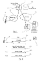
- a waking state management equipment 1 independent of the provider of the network in question, manages waking state information of a radiocommunication terminal 2, and sets this information is available to service providers or content 3 outside the network.
- figure 1 A single radiocommunication terminal 2.
- the invention also applies, of course, to the case where the waking state management equipment 1 manages waking state information for several radiocommunication terminals, and preferably in which case the activity state of all the terminals of the network is managed by one or more waking state management equipment 1.
- Terminal 2 belongs to a UMTS standard radiocommunication network 4, also called a 3G network (for "third generation radio communication network”).
- the invention applies of course also to any other type of radio communication network, and in particular to networks GPRS standard (also called 2.5G network) or GSM, especially if it is taken in combination with a protocol type WAP (English “Wireless Application Protocol").
- Service providers 3 are, in the example of the figure 1 connected to the waking state management equipment 1 via an Internet-type network 5, such as for example the global Internet network.
- the network 5 may also be of any other type, and may in particular be a UMTS, GPRS or GSM standard radiocommunication network.
- Service provider 3 here means any server of the communication network 5 for which the knowledge of the waking state of the terminal 2 represents useful information.
- a service provider may be, for example, a content provider, a location server of the terminal 2, or an information broadcast server.
- the service provider 3 may in particular be internal or external to the network 4, and in a particular embodiment of the invention, the service provider 3 may be included in the architecture of the network 4, or may be the operator of the network 4 himself.
- the waking state management equipment 1 comprises, on the example of the figure 1 , an alert state server 11, which analyzes the activity of the terminal 2 to deduce information on its waking state, and a waking state database 12, which stores the information deduced by the server 11.
- the server 11 and the database 12 can be integrated within the same management equipment 1, or be remote. In this second case, it is possible, for example, to envisage that the server 11 is connected to the radio communication network 4, and that the database 12 is connected to another communication network, for example of the internet type.
- the server 11 and the database 12 then comprise specific means enabling them to exchange data, and in particular the waking state information of the terminal 2.
- the terminal 2 has a waking state application that transmits at regular intervals to the waking state server 11, a datagram indicating that it is in an active state.
- the waking state server 11 deduces that the terminal 2 has gone into an inactive state. It then transmits this information to the database 12, which updates a status information register, so that the wake status information associated with the terminal 2 takes the value "inactive", thus indicating that the terminal 2 is in a standby state.
- the equipment deduces the state information of wakes up terminal 2 and stores it directly in a state information register.
- a TCP type connection is kept open between the waking state application of the terminal 2 and the waking state server 11.
- the maintenance of this connection has the advantage of being very inexpensive, and to give the wake state server 11 an indication of the unavailability of the terminal 2 when the TCP connection is broken.
- the wake-up state database 12 (or the waking state management equipment 1 in the case where the database 12 and the server 11 are integrated within the same equipment) can then be set to day the status information register, as previously described.
- Such an embodiment may present certain difficulties, especially if too many TCP connections must be maintained simultaneously.
- An alternative embodiment can therefore be envisaged, corresponding to a mixed mode of operation according to which a TCP connection is maintained between the terminal 2 and the waking state server 11 for a determined maximum time, for example according to the constraints of operation of the network 4, then is reallocated later.
- a TCP connection is kept open between the wake state server 11 and the terminal 2, which periodically transmits IP packets (for "Internet Protocol") to the server 11, to inform it, among other things, on its state of activity.
- IP packets for "Internet Protocol”
- the server 11 can analyze the state of the TCP connection (broken or open), then refine the state information by estimating the time elapsed since the reception the last IP packet (greater or less than a predetermined threshold).
- the server 11 can further refine the waking state information associated with the terminal 2 by analyzing the contents of the received IP packet.
- the waking state application of the terminal 2 can insert in the IP packet transmitted to the server 11, information relating to the state of activity that it wishes to indicate to the server 11.
- the terminal 2 can be turned on, but its user can tell the server 11 that it does not wish to be seen as active, except for example for emergencies.
- the terminal 2 sends an HTTP request, which results in a request to establish a TCP connection.
- An application of the terminal 2 may request the communication network 4, of GPRS type for example, the establishment of a context PDP (in English "Packet Description Protocol" for "packet description protocol”). This then results in the reservation of an IP address allocated to the terminal 2, for which it is then possible to route packets through the GPRS network 4.
- This context implies that radio resources are allocated to the terminal 2 when, for example, data is sent or received by the latter.
- Such an external IP address is established by the network 4 of the operator for a predetermined duration which corresponds to the PDP context establishment time.
- Such a duration is greater than the duration of a TCP connection.
- the network 4 associates with each PDP context a timer, which is deactivated beyond a predetermined maximum duration. Such a characteristic is necessary for the establishment of a Web session by the terminal 2, because such a session includes multiple TCP connections, which must however have the same IP address.
- a PDP context is expensive in terms of network resources.
- Such a PDP context thus makes it possible to maintain a correspondence between a public address and a private address at a router (Gateway GPRS Signaling Node) which connects the GPRS network to the global Internet network.
- a router Gateway GPRS Signaling Node
- the disconnection of the terminal 2 can be detected by the state machines of the TCP protocol.
- the wake state server 11 considers that the state of the terminal 2 does not change during the period separating two successive connections. In other words, the waking state server 11 uses the last status information received from the terminal 2 to determine the active or inactive state of the latter.
- the state server 11 can modify the state of the terminal 2 that it has memorized (and thus deduce from the break in the context that the terminal 2 can no longer be reached). For example, the state server 11 may consider that the terminal 2 is in an unavailable state, or inactive if no new state information has been transmitted to it for a time interval greater than a predetermined threshold, of the order of 10 minutes for example.
- the waking state server 11 manages the waking state information of the terminal 2, but can also manage information relating to the profile of the user subscriber of the terminal 2. This information can be stored in the base wake status data 12.
- the user of the terminal 2 implicitly or explicitly subscribes to the server 11 to an activity protocol, determining in particular the structure of the datagram or the IP packet transmitted to the server 11.
- the protocol of activity determines that the message sent from the terminal 2 to the server 11 has a number of bits, and that each bit is associated with a particular transmission mode, associated with a class of services offered at the terminal 2.
- the same service can of course belong to several distinct classes of services, if several different transmission modes are implemented by the service provider to offer this service to a user.
- a content provider may choose to transmit content to the terminal 2 by WAP type data transmission, and by SMS type notification.
- the wakeup state management equipment 1 or the waking state database 12 can maintain a waking status register containing wakeup state information of the structure next : Bit 1 Notification Bit 2 Normal voice Bit 3 Urgent Voice Bit 4 Normal WAP push Bit 5 Urgent WAP push Bit 6 Filtered Voice
- Each bit 1 to 6 is associated with a transmission mode preferentially used for a class of services to which the terminal 2 can access via the communication network 4.
- the bit 1 corresponds to the transmission and / or reception by the terminal 2 notifications, for example SMS type.
- Bits 2 and 3 correspond to the possibility of receiving normal or urgent type calls.
- Bits 4 and 5 are associated with data transmission as part of the WAP protocol.
- the server 11 can deduce that the terminal 2 must be considered as active for all the modes of transmission above. Conversely, if all the bits are set to 0, the user wants his terminal 2 to be considered in a standby state vis-à-vis all modes of transmission, and therefore does not wish to be disturbed.
- the server 11 can therefore deduce that the user accepts to receive notifications (for example short messages) and urgent calls, but wishes to be considered as inactive, and therefore unavailable, for all other modes of transmission implemented in the network 4 .
- Identification information is also associated with the user of the terminal 2 and transmitted in the datagram to the wake up state server 11.
- the server 11 can then interpret the protocol used in the IP packet received, according to this identification information. It can indeed keep in memory a table associating with each UserID of the radiocommunication network 4 an activity protocol.
- the user's MSISDN of terminal 2 can be used as identification information.
- identification information For example, the user's MSISDN of terminal 2 can be used as identification information.
- the terminal 2 wishes to be able to access a service proposed by a service provider 3 having an APN (in English "Access Point Name” for "access point name”) particular for its service, the wakeup state application of the terminal 2 attached to the datagram transmitted to the server 11 in an IP packet, the "public" IP address by which the user of the terminal 2 can be reached.
- APN in English "Access Point Name” for "access point name”
- a TCP connection can be established between the terminal 2 and the equipment 1 (or the database 12), and information authentication can be added to the IP packet transiting between the terminal 2 and the equipment 1 during the establishment of the session.
- the waking state information relating to the terminal 2, updated by the waking state server 11, can then be made available to the service providers 3 via the network 5.
- Several mechanisms can be considered in the context of the invention to do this.
- the database 12 (or the equipment 1) stores the addresses of a plurality of service providers 3, and that it sends a notification to all these service providers 3 each time Awakening state information associated with terminal 2 changes value.
- a service provider 3 performs regularly, or only when it needs, a survey (in English "polling") with the state management equipment of awakening 1, or with the database 12, to know the state of activity of a terminal 2.
- the invention as illustrated in figure 1 still allows the state server 11 to notify the user of the terminal 2.
- the state server 11 can transmit to the terminal 2 a particular piece of information, or a notification leading its user to fetch a particular piece of information .
- the server 11 can invite the user of the terminal 2 to fetch a WAP page containing notification information for the terminal 2.
- a TCP connection remains open between the terminal 2 and the waking state server 11.
- the terminal 2 sends (21) regularly a synchronization message, called SYN, to the wake status server 11. For example, a SYN is sent every 14 seconds.
- the server 11 acknowledges (22) the received SYN, and the terminal 2 acknowledges (23) in turn the acknowledgment message received from the server 11.
- Initial information is sent (24) by the wakeup state application of the terminal 2 to the server 11 at the initiation of the TCP connection.
- Such initial information includes for example the UserID identification information of the user of the terminal 2, the "public" IP address to which it can be attached, authentication information, as well as the state information. wakeup that the user wishes to signify to the server 11. Subsequently, only the SYNs for maintaining the connection and the waking statuses containing the wakeup state information of the terminal 2 are sent to the server 11.
- the volume of user information transmitted by the terminal 2 is advantageously restricted.
- the terminal 2 belongs to a radio communication network 4 to the GPRS standard.
- the UDP protocol is the protocol used by the WAP for its transport between a mobile terminal and the WAP gateway.
- a "bearer" connection is thus established in the GPRS network 4 between the mobile terminal 2 and the GPRS gateway "Service Node", called GGSN.
- GGSN Service Node
- This support will last for a configurable time in the network, independent of the service running over UDP.
- a "bearer” connection is a lower level connection mode for transporting IP packets between two points.
- the PDP protocol in English “Packet Description Protocol” for "packet description protocol" used in a modem connection.
- the gateway GGSN then maintains a correspondence between an IP address allocated dynamically to the terminal 2 during the establishment of the bearer service, and the identification information of the terminal 2.
- the waking state application implemented by the terminal 2 sends (31) initialization information to the server 11, including its UserID, authentication information, the "public" IP address to which it can be joined, and the information specific to its state.
- a session is then established, and the server 11 sends (32) to the terminal 2 a datum called SessionID to identify the session.
- SessionID a datum called SessionID to identify the session.
- a first IP address, rated @ IP1 on the figure 3 is associated with the terminal 2.
- IP2 IP2
- the data packet sent by the terminal 2 to the server 11 contains little information. It can therefore be envisaged in the context of the invention that the server 11 sends a response to the terminal 2 on receipt of the data packet.
- a response, or feedback can be for example push information, that is to say a notification.
- the structure of the return information can use the principles of the e-mail, the Web and the SIP protocol, and for example consist of blocks of information type MIME.
- such return information has the following structure: Voice Notification Normal in Vmail Voice Notification Urgent in Vmail Normal WAP push Urgent WAP push Urgent email Normal email "SMS like message"
- the "Voice Notification” field is used to indicate to the user that he must go to his voice mailbox
- the "Normal WAP Push” and “Urgent WAP Push” fields are used to indicate to the user that he can go for a WAP page (Push type).
- the service provider 3 sends XYZ content to the waking state management equipment 1, intended for the user of the terminal 2.
- the equipment 1 (for example by means of the database 12 illustrated in figure 1 ) returns back to it (42) information indicating that the terminal 2 is in a standby state for this type of service.
- the service provider 3 sends to the equipment 1 a new content XYZ 'intended to replace the previously transmitted XYZ content.
- the equipment 1 having received (44) from the terminal 2 information indicating that it was in active state, transmits the content XYZ 'to the terminal 2 during a step referenced 45.
- the equipment 1 comprises a wake-up state server 11 and a wake-up state database 12
- the server 11 transmits the content XYZ 'to the terminal 2, on validation of the active state of the terminal 2 by the database 12.
- the terminal 2 can then acknowledge (46) the reception of this content.
- the wakeup state management equipment 1 then acknowledges (47) the service provider 3 sending the content message XYZ 'to the user of the terminal 2.
- the waking state management equipment 1 plays a role similar to that of SMS short message sending systems of the prior art, without being connected to the HLR register implemented in the networks conventional radiocommunication
Claims (18)
- Verfahren zur Verwaltung des Wachzustands von mindestens einem Endgerät eines Funknetzes, wobei das Netz den Zugriff des Endgeräts auf mindestens einen Dienst ermöglicht,
dadurch gekennzeichnet, dass es einen Schritt zur Analyse des Betriebs des Endgeräts durch eine auf die Verwaltung des Wachzustands zugeschnittene Ausrüstung ausführt, der eine Wachzustandsinformation des Endgeräts liefert, auf die mindestens ein in Bezug auf das Funknetz interner oder externer Dienstleister zugreifen kann,
dadurch, dass die Wachzustandsinformation selektiv Auskunft über den Wachzustand des Endgeräts in Bezug auf ein Übertragungsverfahren gibt, das einer Klasse eines Dienstes oder von Diensten zugehörig ist,
und dadurch, dass die auf die Verwaltung des Wachzustands zugeschnittene Ausrüstung mit dem Funknetz verbunden ist. - Verwaltungsverfahren nach Anspruch 1, dadurch gekennzeichnet, dass die auf die Verwaltung des Wachzustands zugeschnittene Ausrüstung Folgendes umfasst:- mindestens einen Wachzustandsserver, der den Analyseschritt ausführt;- mindestens eine Wachzustandsdatenbank, die einen Schritt zum Speichern der Wachzustandsinformation ausführt.
- Verwaltungsverfahren nach Anspruch 2, dadurch gekennzeichnet, dass über das Funknetz und/oder über mindestens ein anderes Nachrichtennetz auf die Datenbank zugegriffen werden kann.
- Verwaltungsverfahren nach einem der Ansprüche 2 und 3, dadurch gekennzeichnet, dass der Wachzustandsserver während des Analyseschritts den Zustand einer zwischen einer durch das Endgerät ausgeführten Wachanwendung und dem Wachzustandsserver hergestellten Verbindung analysiert,
und dadurch, dass die Wachzustandsinformation einen ersten, "aktiven" Wert, wenn die Verbindung offen ist, und einen zweiten, "inaktiven" Wert annimmt, wenn die Verbindung unterbrochen ist. - Verwaltungsverfahren nach Anspruch 4, dadurch gekennzeichnet, dass die Verbindung gemäß einem Protokoll des Typs TCP (in Englisch "Transmission Control Protocol" für "Übertragungskontrollprotokoll") ausgeführt wird.
- Verwaltungsverfahren nach einem der Ansprüche 4 bis 5, dadurch gekennzeichnet, dass die Verbindung nach einer vorbestimmten Höchstzeit unterbrochen und der Wachanwendung des Endgeräts zu einem späteren Zeitpunkt neu zugewiesen wird.
- Verwaltungsverfahren nach einem der Ansprüche 2 bis 6, dadurch gekennzeichnet, dass der Wachzustandsserver während des Analyseschritts die Dauer analysiert, die seit dem letzten Empfang eines durch eine durch das Endgerät ausgeführte Wachanwendung an den Wachzustandsserver übertragenen Pakets verstrichen ist,
und dadurch, dass die Wachzustandsinformation einen ersten, "aktiven" Wert, wenn die Dauer niedriger als ein vorbestimmter Schwellenwert ist, und einen zweiten, "inaktiven" Wert annimmt, wenn die Dauer höher ist als der vorbestimmte Schwellenwert. - Verwaltungsverfahren nach einem der Ansprüche 1 bis 7, dadurch gekennzeichnet, dass der Wachzustandsserver während des Analyseschritts den Inhalt einer durch eine durch das Endgerät ausgeführte Wachanwendung an den Wachzustandsserver übertragenen Zustandsmeldung analysiert, um davon die Wachinformation des Endgeräts abzuleiten.
- Verwaltungsverfahren nach Anspruch 8, dadurch gekennzeichnet, dass die Zustandsmeldung eine binäre Meldung ist, die mehrere Bits umfasst, wobei jedes der Bits mindestens einem Übertragungsverfahren zugehörig ist,
und dadurch, dass der Wachzustandsserver während des Analyseschritts den Wert von jedem der Bits bestimmt und davon den Wachzustand des Endgeräts in Bezug auf mindestens ein zugehöriges Übertragungsverfahren ableitet,
wobei ein Bit mit Wert 0 beziehungsweise 1 angibt, dass das Endgerät sich für das oder die zugehörige/n Übertragungsverfahren in einem inaktiven beziehungsweise aktiven Zustand befindet, oder umgekehrt. - Verwaltungsverfahren nach einem der Ansprüche 8 und 9, dadurch gekennzeichnet, dass der Austausch zwischen der durch das Endgerät ausgeführten Wachanwendung und dem Wachzustandsserver gemäß einem bestimmten Betriebsprotokoll ausgeführt wird, das eine Struktur der Zustandsmeldung definiert.
- Verwaltungsverfahren nach einem der Ansprüche 8 bis 10, dadurch gekennzeichnet, dass die Zustandsmeldung ferner eine Kennungsinformation eines Benutzers des Endgeräts umfasst.
- Verwaltungsverfahren nach Anspruch 11, dadurch gekennzeichnet, dass der Wachzustandsserver das ausgeführte Betriebsprotokoll in Abhängigkeit von der Kennungsinformation bestimmt.
- Verwaltungsverfahren nach einem der Ansprüche 8 bis 12, dadurch gekennzeichnet, dass die Zustandsmeldung ferner mindestens eine der folgenden Informationen umfasst:- eine Authentifizierungsinformation;- eine öffentliche IP-Adresse (IP = Internet-Protokoll) des Benutzers.
- Verwaltungsverfahren nach einem der Ansprüche 2 bis 13, dadurch gekennzeichnet, dass es ferner einen Schritt der Zurverfügungstellung der Wachzustandsinformation für den mindestens einen der Dienstleister durch die Wachzustandsdatenbank umfasst.
- Verfahren nach Anspruch 14, dadurch gekennzeichnet, dass die Datenbank während des Schritts der Zurverfügungstellung die Wachzustandsinformation als Antwort auf eine Anfrage des Dienstleisters überträgt.
- Verwaltungsverfahren nach einem der Ansprüche 14 und 15, dadurch gekennzeichnet, dass die Wachzustandsdatenbank den Schritt der Zurverfügungstellung bei jeder Änderung des Werts der Wachzustandsinformation ausführt.
- Verwaltungsverfahren nach einem der Ansprüche 1 bis 16, dadurch gekennzeichnet, dass es ferner einen Schritt der Übertragung einer Informationsmeldung durch den Wachzustandsserver an den Benutzer umfasst.
- Verwaltungsverfahren nach Anspruch 17, dadurch gekennzeichnet, dass das Format der Informationsmeldung vom Typ MIME ("Multipurpose Internet Mail Extension") ist.
Applications Claiming Priority (2)
| Application Number | Priority Date | Filing Date | Title |
|---|---|---|---|
| FR0104674 | 2001-04-05 | ||
| FR0104674A FR2823411B1 (fr) | 2001-04-05 | 2001-04-05 | Procede de gestion de l'etat d'eveil d'un terminal de radiocommunication |
Publications (2)
| Publication Number | Publication Date |
|---|---|
| EP1248488A1 EP1248488A1 (de) | 2002-10-09 |
| EP1248488B1 true EP1248488B1 (de) | 2012-05-09 |
Family
ID=8862011
Family Applications (1)
| Application Number | Title | Priority Date | Filing Date |
|---|---|---|---|
| EP02364016A Expired - Lifetime EP1248488B1 (de) | 2001-04-05 | 2002-03-28 | Verfahren zur Bestimmung des Zustands eines Kommunikationsendgerät |
Country Status (4)
| Country | Link |
|---|---|
| US (1) | US20020188714A1 (de) |
| EP (1) | EP1248488B1 (de) |
| AT (1) | ATE557554T1 (de) |
| FR (1) | FR2823411B1 (de) |
Families Citing this family (17)
| Publication number | Priority date | Publication date | Assignee | Title |
|---|---|---|---|---|
| EP1257086A2 (de) * | 2001-05-07 | 2002-11-13 | Siemens Aktiengesellschaft | Vorrichtung und Verfahren zum Übersenden von Information |
| US6748434B2 (en) * | 2001-09-18 | 2004-06-08 | Ericsson Inc. | Adaptive node selection |
| US7321920B2 (en) | 2003-03-21 | 2008-01-22 | Vocel, Inc. | Interactive messaging system |
| US20040249953A1 (en) * | 2003-05-14 | 2004-12-09 | Microsoft Corporation | Peer-to-peer instant messaging |
| US8516498B2 (en) * | 2003-10-31 | 2013-08-20 | Microsoft Corporation | Handling a delivery failure as a program exception in a distributed asynchronous architecture |
| US20060221893A1 (en) * | 2005-04-01 | 2006-10-05 | Nokia Corporation | System, network entity, method, mobile device and computer program product for correlating device identifiers in mobile networks |
| US20060223593A1 (en) * | 2005-04-01 | 2006-10-05 | Ixi Mobile (R&D) Ltd. | Content delivery system and method for a mobile communication device |
| US8285312B2 (en) * | 2006-12-06 | 2012-10-09 | Research In Motion Limited | Method and apparatus for deriving presence information using message traffic analysis |
| US20080307036A1 (en) * | 2007-06-07 | 2008-12-11 | Microsoft Corporation | Central service allocation system |
| US20090063686A1 (en) * | 2007-08-30 | 2009-03-05 | Schmidt Brian K | Automated service discovery and dynamic connection management |
| JP5444639B2 (ja) | 2007-11-20 | 2014-03-19 | パナソニック株式会社 | サーバ装置と分散サーバシステム |
| US9628831B2 (en) | 2010-03-25 | 2017-04-18 | Whatsapp, Inc. | Multimedia transcoding method and system for mobile devices |
| US8995965B1 (en) * | 2010-03-25 | 2015-03-31 | Whatsapp Inc. | Synthetic communication network method and system |
| US20140335852A1 (en) * | 2013-03-14 | 2014-11-13 | Wenlong Li | Cross-device notification apparatus and method |
| CA2911719A1 (en) | 2013-04-16 | 2014-10-23 | Imageware Systems, Inc. | Conditional and situational biometric authentication and enrollment |
| US9286528B2 (en) | 2013-04-16 | 2016-03-15 | Imageware Systems, Inc. | Multi-modal biometric database searching methods |
| CN109660613B (zh) * | 2018-12-11 | 2021-10-22 | 网宿科技股份有限公司 | 文件传输方法及系统 |
Family Cites Families (20)
| Publication number | Priority date | Publication date | Assignee | Title |
|---|---|---|---|---|
| US6058303A (en) * | 1996-08-30 | 2000-05-02 | Telefonaktiebolaget L M Ericsson (Publ) | System and method for subscriber activity supervision |
| FI105873B (fi) * | 1997-04-03 | 2000-10-13 | Nokia Networks Oy | Lyhytsanomien välitys pakettiradioverkossa |
| US6212175B1 (en) * | 1997-04-22 | 2001-04-03 | Telxon Corporation | Method to sustain TCP connection |
| US6175616B1 (en) * | 1997-11-03 | 2001-01-16 | Elliott Light | Method and apparatus for obtaining telephone status over a network |
| US6430289B1 (en) * | 1999-04-13 | 2002-08-06 | Microsoft Corporation | System and method for computerized status monitor and use in a telephone network |
| US6625437B1 (en) * | 1999-09-23 | 2003-09-23 | Sprint Spectrum, L.P. | Location and events reporting in a wireless telecommunications network |
| US7366522B2 (en) * | 2000-02-28 | 2008-04-29 | Thomas C Douglass | Method and system for location tracking |
| US6716101B1 (en) * | 2000-06-28 | 2004-04-06 | Bellsouth Intellectual Property Corporation | System and method for monitoring the location of individuals via the world wide web using a wireless communications network |
| EP1173037B1 (de) * | 2000-07-14 | 2006-03-22 | NTT DoCoMo, Inc. | Standortsregistrationsverfahren mit Unterstützung für mehrere SIM Karten mit unterschiedlichen Funktionen |
| US20020025795A1 (en) * | 2000-08-24 | 2002-02-28 | Msafe Inc., | Method, system and device for monitoring activity of a wireless communication device |
| US6714519B2 (en) * | 2000-11-03 | 2004-03-30 | Vocaltec Communications Limited | Communications availability |
| US20020055967A1 (en) * | 2000-11-08 | 2002-05-09 | Coussement Stefaan Valere Albert | System for reporting client status information to communications-center agents |
| US20020056000A1 (en) * | 2000-11-08 | 2002-05-09 | Albert Coussement Stefaan Valere | Personal interaction interface for communication-center customers |
| US20040127193A1 (en) * | 2002-12-31 | 2004-07-01 | Timmins Timothy A. | Technique for identifying status of users and status of subscribers' accounts in a communications system |
| US20030117316A1 (en) * | 2001-12-21 | 2003-06-26 | Steve Tischer | Systems and methods for locating and tracking a wireless device |
| US6658095B1 (en) * | 2002-03-19 | 2003-12-02 | Nortel Networks Limited | Customized presence information delivery |
| US7155526B2 (en) * | 2002-06-19 | 2006-12-26 | Azaire Networks, Inc. | Method and system for transparently and securely interconnecting a WLAN radio access network into a GPRS/GSM core network |
| US7555108B2 (en) * | 2002-10-01 | 2009-06-30 | Nortel Networks Limited | Presence information for telephony users |
| US20040203581A1 (en) * | 2002-10-07 | 2004-10-14 | Msafe Ltd. | Method system and device for monitoring data pushed to a wireless communication device |
| WO2004077848A2 (en) * | 2003-02-21 | 2004-09-10 | Ge Interlogix, Inc. | Key control with real time communications to remote locations |
-
2001
- 2001-04-05 FR FR0104674A patent/FR2823411B1/fr not_active Expired - Fee Related
-
2002
- 2002-03-28 AT AT02364016T patent/ATE557554T1/de active
- 2002-03-28 EP EP02364016A patent/EP1248488B1/de not_active Expired - Lifetime
- 2002-03-29 US US10/115,450 patent/US20020188714A1/en not_active Abandoned
Also Published As
| Publication number | Publication date |
|---|---|
| EP1248488A1 (de) | 2002-10-09 |
| US20020188714A1 (en) | 2002-12-12 |
| FR2823411A1 (fr) | 2002-10-11 |
| ATE557554T1 (de) | 2012-05-15 |
| FR2823411B1 (fr) | 2003-06-27 |
Similar Documents
| Publication | Publication Date | Title |
|---|---|---|
| EP1248488B1 (de) | Verfahren zur Bestimmung des Zustands eines Kommunikationsendgerät | |
| US11589209B2 (en) | System and methods for data communications in a wireless communication system | |
| US6839554B2 (en) | Method and apparatus for sharing mobile user event information between wireless networks and fixed IP networks | |
| US6668167B2 (en) | Method and apparatus for sharing mobile user event information between wireless networks and fixed IP networks | |
| US8359013B2 (en) | System and methods for wireless messaging | |
| FR2868643A1 (fr) | Methode de decouverte d'appareils connectes a un reseau ip et appareil implementant la methode | |
| WO2006070339A2 (en) | Method and apparatus for presence status facilitation by an access gateway in a mobile communications system | |
| EP1169876B1 (de) | Verfahren und system zum bereitstellen von diensten an mobilstationen im aktivzustand | |
| EP3085065B1 (de) | Verfahren zur aktualisierung der von einem dns server erhaltenen informationen. | |
| WO2009049380A1 (en) | Presence-awareness for wireless devices | |
| EP2011357A1 (de) | Funkbetriebsmittelverwaltung in einem funktelekommunikationsnetz | |
| WO2011064492A1 (fr) | Procede de basculement d'un hss primaire sur un hss de secours dans un reseau ip | |
| EP2210396B1 (de) | System zur herstellung einer verbindung zwischen mindestens einer kommunikationsvorrichtung und mindestens einem ferninformationssystem sowie verbindungsverfahren | |
| WO2009007624A1 (fr) | Procédé et dispositif de gestion d'accès à un réseau mobile de télécommunication via un réseau d'accès | |
| EP2206384B1 (de) | Zugangsknoten-umschaltverfahren | |
| US8204941B1 (en) | Presence updating with preferred service determination | |
| WO2012035236A1 (fr) | Gestion de l'acces au statut d'une ressource | |
| EP4338375A1 (de) | Verfahren zur abwehr eines versuchs, zwei einheiten zu trennen, und zugehöriges system | |
| EP1872530B1 (de) | Verfahren zum senden eines informationscodes zwischen zwei kommunikationseinrichtungen | |
| WO2006087455A1 (fr) | Procede de transmission de messages multimedia et systeme pour la mise en œuvre du procede | |
| WO2012056159A1 (fr) | Procedes et reseau dans lesquels un terminal peut passer en mode veille | |
| FR2853181A1 (fr) | Indicateur d'etat connecte/deconnecte d'un terminal a un reseau de paquets | |
| FR2965999A1 (fr) | Procede de traitement des flux de presence dans un reseau sip |
Legal Events
| Date | Code | Title | Description |
|---|---|---|---|
| PUAI | Public reference made under article 153(3) epc to a published international application that has entered the european phase |
Free format text: ORIGINAL CODE: 0009012 |
|
| AK | Designated contracting states |
Kind code of ref document: A1 Designated state(s): AT BE CH CY DE DK ES FI FR GB GR IE IT LI LU MC NL PT SE TR |
|
| AX | Request for extension of the european patent |
Free format text: AL;LT;LV;MK;RO;SI |
|
| 17P | Request for examination filed |
Effective date: 20020926 |
|
| RAP1 | Party data changed (applicant data changed or rights of an application transferred) |
Owner name: CEGETEL GROUPE |
|
| AKX | Designation fees paid |
Designated state(s): AT BE CH CY DE DK ES FI FR GB GR IE IT LI LU MC NL PT SE TR |
|
| 17Q | First examination report despatched |
Effective date: 20031002 |
|
| RAP1 | Party data changed (applicant data changed or rights of an application transferred) |
Owner name: SOCIETE FRANEAISE DU RADIOTELEPHONE-SFR |
|
| REG | Reference to a national code |
Ref country code: DE Ref legal event code: R079 Ref document number: 60242855 Country of ref document: DE Free format text: PREVIOUS MAIN CLASS: H04Q0007380000 Ipc: H04W0008220000 |
|
| RIC1 | Information provided on ipc code assigned before grant |
Ipc: H04W 8/22 20090101AFI20110929BHEP |
|
| GRAP | Despatch of communication of intention to grant a patent |
Free format text: ORIGINAL CODE: EPIDOSNIGR1 |
|
| GRAS | Grant fee paid |
Free format text: ORIGINAL CODE: EPIDOSNIGR3 |
|
| GRAA | (expected) grant |
Free format text: ORIGINAL CODE: 0009210 |
|
| AK | Designated contracting states |
Kind code of ref document: B1 Designated state(s): AT BE CH CY DE DK ES FI FR GB GR IE IT LI LU MC NL PT SE TR |
|
| REG | Reference to a national code |
Ref country code: GB Ref legal event code: FG4D Free format text: NOT ENGLISH |
|
| REG | Reference to a national code |
Ref country code: CH Ref legal event code: EP Ref country code: AT Ref legal event code: REF Ref document number: 557554 Country of ref document: AT Kind code of ref document: T Effective date: 20120515 |
|
| REG | Reference to a national code |
Ref country code: IE Ref legal event code: FG4D Free format text: LANGUAGE OF EP DOCUMENT: FRENCH |
|
| REG | Reference to a national code |
Ref country code: DE Ref legal event code: R096 Ref document number: 60242855 Country of ref document: DE Effective date: 20120712 |
|
| REG | Reference to a national code |
Ref country code: NL Ref legal event code: VDEP Effective date: 20120509 |
|
| PG25 | Lapsed in a contracting state [announced via postgrant information from national office to epo] |
Ref country code: SE Free format text: LAPSE BECAUSE OF FAILURE TO SUBMIT A TRANSLATION OF THE DESCRIPTION OR TO PAY THE FEE WITHIN THE PRESCRIBED TIME-LIMIT Effective date: 20120509 Ref country code: CY Free format text: LAPSE BECAUSE OF FAILURE TO SUBMIT A TRANSLATION OF THE DESCRIPTION OR TO PAY THE FEE WITHIN THE PRESCRIBED TIME-LIMIT Effective date: 20120509 Ref country code: FI Free format text: LAPSE BECAUSE OF FAILURE TO SUBMIT A TRANSLATION OF THE DESCRIPTION OR TO PAY THE FEE WITHIN THE PRESCRIBED TIME-LIMIT Effective date: 20120509 |
|
| REG | Reference to a national code |
Ref country code: AT Ref legal event code: MK05 Ref document number: 557554 Country of ref document: AT Kind code of ref document: T Effective date: 20120509 |
|
| PG25 | Lapsed in a contracting state [announced via postgrant information from national office to epo] |
Ref country code: PT Free format text: LAPSE BECAUSE OF FAILURE TO SUBMIT A TRANSLATION OF THE DESCRIPTION OR TO PAY THE FEE WITHIN THE PRESCRIBED TIME-LIMIT Effective date: 20120910 Ref country code: GR Free format text: LAPSE BECAUSE OF FAILURE TO SUBMIT A TRANSLATION OF THE DESCRIPTION OR TO PAY THE FEE WITHIN THE PRESCRIBED TIME-LIMIT Effective date: 20120810 |
|
| PG25 | Lapsed in a contracting state [announced via postgrant information from national office to epo] |
Ref country code: NL Free format text: LAPSE BECAUSE OF FAILURE TO SUBMIT A TRANSLATION OF THE DESCRIPTION OR TO PAY THE FEE WITHIN THE PRESCRIBED TIME-LIMIT Effective date: 20120509 Ref country code: AT Free format text: LAPSE BECAUSE OF FAILURE TO SUBMIT A TRANSLATION OF THE DESCRIPTION OR TO PAY THE FEE WITHIN THE PRESCRIBED TIME-LIMIT Effective date: 20120509 Ref country code: DK Free format text: LAPSE BECAUSE OF FAILURE TO SUBMIT A TRANSLATION OF THE DESCRIPTION OR TO PAY THE FEE WITHIN THE PRESCRIBED TIME-LIMIT Effective date: 20120509 |
|
| PG25 | Lapsed in a contracting state [announced via postgrant information from national office to epo] |
Ref country code: IT Free format text: LAPSE BECAUSE OF FAILURE TO SUBMIT A TRANSLATION OF THE DESCRIPTION OR TO PAY THE FEE WITHIN THE PRESCRIBED TIME-LIMIT Effective date: 20120509 |
|
| PLBE | No opposition filed within time limit |
Free format text: ORIGINAL CODE: 0009261 |
|
| STAA | Information on the status of an ep patent application or granted ep patent |
Free format text: STATUS: NO OPPOSITION FILED WITHIN TIME LIMIT |
|
| 26N | No opposition filed |
Effective date: 20130212 |
|
| PG25 | Lapsed in a contracting state [announced via postgrant information from national office to epo] |
Ref country code: ES Free format text: LAPSE BECAUSE OF FAILURE TO SUBMIT A TRANSLATION OF THE DESCRIPTION OR TO PAY THE FEE WITHIN THE PRESCRIBED TIME-LIMIT Effective date: 20120820 |
|
| REG | Reference to a national code |
Ref country code: DE Ref legal event code: R097 Ref document number: 60242855 Country of ref document: DE Effective date: 20130212 |
|
| PG25 | Lapsed in a contracting state [announced via postgrant information from national office to epo] |
Ref country code: MC Free format text: LAPSE BECAUSE OF NON-PAYMENT OF DUE FEES Effective date: 20130331 |
|
| REG | Reference to a national code |
Ref country code: IE Ref legal event code: MM4A |
|
| PG25 | Lapsed in a contracting state [announced via postgrant information from national office to epo] |
Ref country code: IE Free format text: LAPSE BECAUSE OF NON-PAYMENT OF DUE FEES Effective date: 20130328 |
|
| REG | Reference to a national code |
Ref country code: FR Ref legal event code: GC Effective date: 20150310 |
|
| PG25 | Lapsed in a contracting state [announced via postgrant information from national office to epo] |
Ref country code: TR Free format text: LAPSE BECAUSE OF FAILURE TO SUBMIT A TRANSLATION OF THE DESCRIPTION OR TO PAY THE FEE WITHIN THE PRESCRIBED TIME-LIMIT Effective date: 20120509 |
|
| PG25 | Lapsed in a contracting state [announced via postgrant information from national office to epo] |
Ref country code: LU Free format text: LAPSE BECAUSE OF NON-PAYMENT OF DUE FEES Effective date: 20130328 |
|
| REG | Reference to a national code |
Ref country code: FR Ref legal event code: PLFP Year of fee payment: 15 |
|
| REG | Reference to a national code |
Ref country code: FR Ref legal event code: PLFP Year of fee payment: 16 |
|
| REG | Reference to a national code |
Ref country code: FR Ref legal event code: PLFP Year of fee payment: 17 |
|
| REG | Reference to a national code |
Ref country code: FR Ref legal event code: GC Effective date: 20180111 |
|
| PGFP | Annual fee paid to national office [announced via postgrant information from national office to epo] |
Ref country code: DE Payment date: 20190219 Year of fee payment: 18 Ref country code: CH Payment date: 20190222 Year of fee payment: 18 Ref country code: GB Payment date: 20190222 Year of fee payment: 18 |
|
| PGFP | Annual fee paid to national office [announced via postgrant information from national office to epo] |
Ref country code: FR Payment date: 20190220 Year of fee payment: 18 Ref country code: BE Payment date: 20190222 Year of fee payment: 18 |
|
| REG | Reference to a national code |
Ref country code: DE Ref legal event code: R119 Ref document number: 60242855 Country of ref document: DE |
|
| REG | Reference to a national code |
Ref country code: CH Ref legal event code: PL |
|
| REG | Reference to a national code |
Ref country code: BE Ref legal event code: MM Effective date: 20200331 |
|
| PG25 | Lapsed in a contracting state [announced via postgrant information from national office to epo] |
Ref country code: FR Free format text: LAPSE BECAUSE OF NON-PAYMENT OF DUE FEES Effective date: 20200331 Ref country code: CH Free format text: LAPSE BECAUSE OF NON-PAYMENT OF DUE FEES Effective date: 20200331 Ref country code: DE Free format text: LAPSE BECAUSE OF NON-PAYMENT OF DUE FEES Effective date: 20201001 Ref country code: LI Free format text: LAPSE BECAUSE OF NON-PAYMENT OF DUE FEES Effective date: 20200331 |
|
| PG25 | Lapsed in a contracting state [announced via postgrant information from national office to epo] |
Ref country code: BE Free format text: LAPSE BECAUSE OF NON-PAYMENT OF DUE FEES Effective date: 20200331 |
|
| GBPC | Gb: european patent ceased through non-payment of renewal fee |
Effective date: 20200328 |
|
| PG25 | Lapsed in a contracting state [announced via postgrant information from national office to epo] |
Ref country code: GB Free format text: LAPSE BECAUSE OF NON-PAYMENT OF DUE FEES Effective date: 20200328 |