EP1248437A2 - Netzwerkauthentifizierung System, Verfahren, Program, Bereitstellungvorrichtung, Zertifikatsautorität, und Benutzerendgerät - Google Patents
Netzwerkauthentifizierung System, Verfahren, Program, Bereitstellungvorrichtung, Zertifikatsautorität, und Benutzerendgerät Download PDFInfo
- Publication number
- EP1248437A2 EP1248437A2 EP02090132A EP02090132A EP1248437A2 EP 1248437 A2 EP1248437 A2 EP 1248437A2 EP 02090132 A EP02090132 A EP 02090132A EP 02090132 A EP02090132 A EP 02090132A EP 1248437 A2 EP1248437 A2 EP 1248437A2
- Authority
- EP
- European Patent Office
- Prior art keywords
- certificate
- collation result
- service providing
- user
- user terminal
- Prior art date
- Legal status (The legal status is an assumption and is not a legal conclusion. Google has not performed a legal analysis and makes no representation as to the accuracy of the status listed.)
- Granted
Links
Images


Classifications
-
- H—ELECTRICITY
- H04—ELECTRIC COMMUNICATION TECHNIQUE
- H04L—TRANSMISSION OF DIGITAL INFORMATION, e.g. TELEGRAPHIC COMMUNICATION
- H04L63/00—Network architectures or network communication protocols for network security
- H04L63/08—Network architectures or network communication protocols for network security for authentication of entities
- H04L63/0861—Network architectures or network communication protocols for network security for authentication of entities using biometrical features, e.g. fingerprint, retina-scan
-
- H—ELECTRICITY
- H04—ELECTRIC COMMUNICATION TECHNIQUE
- H04L—TRANSMISSION OF DIGITAL INFORMATION, e.g. TELEGRAPHIC COMMUNICATION
- H04L63/00—Network architectures or network communication protocols for network security
- H04L63/12—Applying verification of the received information
- H04L63/123—Applying verification of the received information received data contents, e.g. message integrity
-
- H—ELECTRICITY
- H04—ELECTRIC COMMUNICATION TECHNIQUE
- H04L—TRANSMISSION OF DIGITAL INFORMATION, e.g. TELEGRAPHIC COMMUNICATION
- H04L2463/00—Additional details relating to network architectures or network communication protocols for network security covered by H04L63/00
- H04L2463/081—Additional details relating to network architectures or network communication protocols for network security covered by H04L63/00 applying self-generating credentials, e.g. instead of receiving credentials from an authority or from another peer, the credentials are generated at the entity itself
-
- H—ELECTRICITY
- H04—ELECTRIC COMMUNICATION TECHNIQUE
- H04L—TRANSMISSION OF DIGITAL INFORMATION, e.g. TELEGRAPHIC COMMUNICATION
- H04L63/00—Network architectures or network communication protocols for network security
- H04L63/08—Network architectures or network communication protocols for network security for authentication of entities
- H04L63/083—Network architectures or network communication protocols for network security for authentication of entities using passwords
Definitions
- the present invention relates to a network authentication system, method, and program, a service providing apparatus, a certificate authority, and a user terminal and, more particularly, to a network authentication system, method, and program, a service providing apparatus, a certificate authority, and a user terminal which perform authentication by using biometrical information of a user in providing a given service on a communication network.
- a user terminal 7 to be accessed by a user detects biometrical information of the user, such as a fingerprint, and a collating unit 71 identifies this biometrical information by collation.
- a collation result 71A is transmitted as a collation result 7A from a communication apparatus 72 to a service providing apparatus 8 across a communication network 9.
- a processing unit 82 performs predetermined processing on the basis of a collation result 81A received by a communication unit 81, thereby providing a service.
- an encryption circuit 74 of the user terminal 7 encrypts the collation result 71A from the collating unit 71 by using an encryption key 73A prestored in a storage circuit 73.
- the result of encryption is transmitted as communication data 7B.
- a decryption circuit 84 of the service providing apparatus 8 decrypts this communication data 7B from the user terminal 7 by using a decryption key 83A prestored in a database 83, thereby obtaining a collation result 84A.
- the service providing apparatus determines whether to provide a service on the basis of the collation result received directly from the user terminal. Therefore, the collation result can easily be tapped, and any third party can easily pose as the user. This lowers the safety.
- each user must register a decryption key corresponding to an encryption key of his or her user terminal into all the service providing apparatuses.
- the key transmission and maintenance require high safety, resulting in an increased system scale and cost.
- a network authentication system comprising a service providing apparatus, a user terminal connected to the service providing apparatus across a communication network to perform authentication by using information of a user himself or herself, and a certificate authority for notifying, across a communication network, the service providing apparatus of a certificate indicating that the information of the user transmitted from the service providing apparatus across a communication network is valid, wherein the user terminal identifies the user by collation by using the information of the user, and notifies the service providing apparatus of the collation result across the communication network, and in accordance with the notification of the collation result from the user terminal, the service providing apparatus requests, across the communication network, the certificate authority to certify the validity of the collation result, and, if the validity of the collation result is certified by a certificate notified from the certificate authority, provides a predetermined service to the user on the basis of the collation result contained in the certificate.
- a network authentication method comprising providing a user terminal connected to a service providing apparatus across a communication network to perform authentication by using biometrical information of a user himself or herself with respect to the service providing apparatus, and a certificate authority for notifying, across the communication network, the service providing apparatus of a certificate indicating that the information of the user transmitted from the service providing apparatus across the communication network is valid, wherein the user terminal identifies the user by collation by using the biometrical information of the user, and notifies the collation result to the service providing apparatus across the communication network, in response to this notification of the collation result from the user terminal, the service providing apparatus requests the certificate authority connected to the communication network to certify the validity of the collation result, in response to this request, the certificate authority certifies the validity of the collation result from the user terminal and notifies a certificate containing the collation result to the service providing apparatus across the communication network, and if the validity of the collation result is certified by the certificate from the certificate authority, the service providing apparatus provides a pre
- a program which uses a user terminal connected to a service providing apparatus across a communication network to perform authentication by using information of a user himself or herself with respect to the service providing apparatus, and a certificate authority for notifying, across the communication network, the service providing apparatus of a certificate indicating that the information of the user transmitted from the service providing apparatus across the communication network is valid, comprising the steps of causing the user terminal to identify the user by collation by using biometrical information of the user, and notify the collation result to the service providing apparatus across the communication network, in response to this notification of the collation result from the user terminal, causing the service providing apparatus to request the certificate authority connected to the communication network to certify the validity of the collation result, in response to this request, causing the certificate authority to certify the validity of the collation result from the user terminal and notify a certificate containing the collation result to the service providing apparatus across the communication network, and if the validity of the collation result is certified by the certificate from the certificate authority, causing the service providing apparatus
- a service providing apparatus for use in a network authentication system in which when authentication is to be performed by using biometrical information of a user himself or herself between a user terminal and the service providing apparatus connected by a communication network, the authentication is performed on the basis of that certification of the validity of a collation result from the user terminal, which is performed by a certificate authority connected across the communication network, wherein in response to notification of the result of user collation performed using the biometrical information of the user in the user terminal, the service providing apparatus requests the certificate authority across the communication network to certify the validity of the collation result and, if the validity of the collation result is certified by a certificate notified from the certificate authority, provides a predetermined service to the user on the basis of the collation result contained in the certificate.
- a certificate authority for use in a network authentication system in which when authentication of a user is to be performed between a user terminal and a service providing apparatus connected by a communication network, the certificate authority connected across the communication network authenticates the validity of a collation result from the user terminal, wherein when, in response to notification of the result of user collation performed using the biometrical information of the user in the user terminal, requested to certify the validity of the collation result by the service providing apparatus across the communication network, the certificate authority certifies the validity of the collation result and notifies a certificate containing the collation result across the communication network, thereby allowing the service providing apparatus to provide a predetermined service to the user on the basis of the collation result contained in the certificate.
- a service providing apparatus for use in a network authentication system in which when authentication of a user is to be performed between a user terminal and the service providing apparatus connected by a communication network, a certificate authority connected across the communication network authenticates the validity of a collation result from the user terminal, wherein in response to the result of user collation in the user terminal, the service providing apparatus requests the certificate authority across the communication network to certify the validity of the collation result, and provides a predetermined service to the user on the basis of the collation result contained in a certificate notified from the certificate authority in response to the request.
- This network authentication system comprises a user terminal 1, a service providing apparatus 2, a certificate authority 3, and communication networks 4A and 4B such as the Internet or telephone networks.
- the user terminal 1 identifies a user himself or herself by collation by using biometrical information of the user.
- the service providing apparatus 2 provides a predetermined service to the user in accordance with the result of collation of the user.
- the certificate authority 3 certifies the validity of the collation result from the user terminal 1, as a third party independent of the user terminal 1 and the service providing apparatus 2.
- the communication networks 4A and 4B connect the user terminal 1, the service providing apparatus 2, and the certificate authority 3.
- a fingerprint is used as biometrical information.
- this biometrical information it is also possible to use, e.g., a voiceprint, iris, handwriting, palm shape (finger joint length), vein pattern, or face layout pattern.
- the user terminal 1 has a collating unit 11, an encryption circuit 13, a storage circuit 12, and a communication unit 14.
- the collating unit 11 identifies a user himself or herself by collation by using biometrical information of the user.
- the encryption circuit 13 encrypts a collation result 11A from the collating unit 11.
- the storage circuit 12 is connected to the encryption circuit 13 and prestores an encryption key (first encryption key) 12B for use in encryption, a terminal ID (terminal identification information) 12A, and user information 12C such as personal information of the user.
- the communication unit 14 receives communication data 13C from the encryption circuit 13 and transmits this communication data 13C to the communication network 4A.
- the collating unit 11 includes, e.g., a sensor for acquiring a fingerprint image, a storage section for prestoring a fingerprint image of the user or registered data indicating the feature of the user's fingerprint, and a collating section for collating the fingerprint image from the sensor with the registered data in the storage section to output the collation result. Details of this collating unit will be described later by taking an example.
- the service providing apparatus 2 has a communication unit 21, a decryption circuit 23, a storage circuit 22, and a processing unit 24.
- the communication unit 21 exchanges various data with the user terminal 1 or the certificate authority across the communication networks 4A and 4B.
- the decryption circuit 23 decrypts an encrypted certificate 34B received by the communication unit 21.
- the storage circuit 22 is connected to the decryption circuit 23 and prestores a decryption key (second decryption key) 22B for use in decryption of an encrypted certificate and an apparatus ID (apparatus identification information) 22A for identifying the service providing apparatus 2.
- the processing unit 24 receives a certificate 34A obtained by the decryption circuit 23 and performs processing on the basis of data, such as the collation result 11A from the user terminal 1, contained in this certificate 34A, thereby providing a predetermined service.
- the certificate authority 3 has a communication unit 31, a terminal database (to be referred to as a terminal DB hereinafter) 32, a decryption circuit 33, an apparatus database (to be referred to as an apparatus DB hereinafter) 35, and an encryption circuit 34.
- the communication apparatus 31 exchanges various data with the service providing apparatus 2 across the communication network 4B.
- the terminal DB 32 stores a decryption key (first decryption key) 32A corresponding to the encryption key 12B of each user terminal 1.
- the decryption circuit 33 decrypts, by using the decryption key 32A stored in the terminal DB 32, encrypted collation data 13B contained in communication data B received by the communication unit 31.
- the apparatus DB 35 stores an encryption key (second encryption key) 35A corresponding to the decryption key 22B of each service providing apparatus 2.
- the encryption circuit 34 encrypts, as a certificate, original collation data 13A obtained by decryption by the decryption circuit 33, by using the encryption key 35A stored in the apparatus DB 35.
- the communication networks 4A and 4B need not be separate communication networks as described above but can be a single communication network.
- a user operates the user terminal 1 to allow the collating unit 11 to sense biometrical information of the user himself or herself, and collate the obtained sensing data with the prestored registered data of the user.
- the collation result 11A is encrypted by the encryption circuit 13 by using the encryption key 12B stored in the storage circuit 12.
- the encryption circuit 13 forms collation data 13A by adding, where necessary, to the collation result 11A the personal user information 12C of the user, e.g., the name, address, telephone number, account number, and credit card number, stored in the storage circuit 12, and encrypts this collation data 13A by using the encryption key 12B.
- the encryption circuit 13 forms communication data A (13C) by adding to the encrypted collation data 13B obtained by encryption the terminal ID 12A stored in the storage circuit 12.
- the communication unit 14 transmits this communication data A (1A) to the service providing apparatus 2 across the communication network 4A.
- communication data B (2A) is formed by adding to the communication data A the apparatus ID 22A stored in the storage circuit 22.
- This communication data B (2A) is transmitted to the certificate authority 3 across the communication network 4B, thereby requesting the certificate authority 3 to certify the validity of the collation result notified from the user terminal 1.
- the terminal DB 32 retrieves the decryption key 32A making a pair with the key stored in the user terminal 1, by using the terminal ID 12A added to the communication data B as a key.
- the decryption circuit 33 uses this decryption key 32A to decrypt the encrypted collation data 13B contained in the communication data B, thereby checking the validity of the data.
- the decryption circuit 33 then outputs the collation data 13A containing the collation result 11A and the user information 12C.
- the apparatus DB 35 retrieves the encryption key 35A making a pair with the key stored in the service providing apparatus 2, by using the apparatus ID 22A added to the communication data B as a key.
- the encryption circuit 34 uses this encryption key 35A to encrypt the collation data 13A from the decryption circuit 33 as a certificate 34A, forming an encrypted certificate 34B.
- the communication unit 31 transmits this encrypted certificate 34B as an encrypted certificate 3A to the service providing apparatus 2 across the communication network 4B.
- the encryption circuit 34 forms an encrypted certificate of a certificate which indicates that no validity is obtained or which indicates failure of collation, and transmits this encrypted certificate to the service providing apparatus 2.
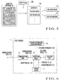
- Fig. 5 explains the process operation (communication data B receiving process) performed in the service providing apparatus 2 when the communication data B is received.
- the decryption circuit 23 decrypts this encrypted certificate 3A by using the decryption key 22B stored in the storage circuit 22.
- the processing unit 24 determines whether to provide a service to the user. Only when the collation result 11A indicates success of collation and so it is determined that the service can be provided, processing for providing the service is performed. Consequently, the user can receive the provision of the service.
- the user terminal 1 for identifying a user himself or herself by collation by using biometrical information of the user the service providing apparatus 2 for providing a predetermined service to the user in accordance with the user collation result, and the certificate authority 3 for authenticating the collation result from the user terminal 1 are connected across the communication networks.
- the service providing apparatus 2 requests the certificate authority 3 to certify the validity of the collation result.
- the certificate authority 3 authenticates the validity of the collation result and notifies the service providing apparatus 2 of the result of the authentication.
- the certificate authority as a third party checks and authenticates the validity of the collation result, so high safety can be obtained.
- this certificate authority can be easily shared by a plurality of user terminals and a plurality of service providing apparatuses, high-level security can be obtained without increasing the system scale and the maintenance cost.
- an encryption scheme using the encryption key 12B and decryption key 32A corresponding to the user terminal 1 is used.
- the certificate authority 3 is to transfer a certificate to the service providing apparatus 2
- an encryption scheme using the encryption key 35A and decryption key 22B corresponding to the service providing apparatus 2 is used.
- the certificate authority 3 retrieves the decryption key 32A from the terminal DB 32 by using the terminal ID added to the collation result transmitted via the service providing apparatus 2 as a key, and retrieves the encryption key 35A from the apparatus DB 35 by using the apparatus ID similarly added to the collation result as a key.
- the collation results and certificates based on the encryption schemes can be exchanged between a plurality of user terminals 1 and the certificate authority 3 and between the certificate authority 3 and a plurality of service providing apparatuses 2.
- high security for the collation results and certificates can be obtained.
- the decryption key of the user terminal and the encryption key of the service providing apparatus are unitarily managed by the certificate authority. This allows the user terminal to manage only its own encryption key and the service providing apparatus to manage only its decryption key. Therefore, the user terminal and the service providing apparatus need not manage and selectively use a plurality of keys. Compared to a system in which a plurality of keys are used, the scale of the apparatus can be decreased, and the speed of the authentication process can be increased.
- the user terminal and the service providing apparatus need to register the encryption keys to the certificate authority only once. So, it is unnecessary to directly exchange encryption keys and decryption keys whenever authentication is performed. Accordingly, the keys can be handled with extremely high safety.
- the user information 12C containing personal information of the user is also transmitted together with the collation result 11A. Accordingly, this personal information of the user can also be transferred from the user terminal 1 to the processing unit 24 of the service providing apparatus 2 at the same time user authentication is performed.
- the certificate authority can raise the operating cost by charging the service provider whenever performing authentication. Consequently, economical and safe services can be provided to general users.
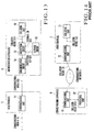
- the user terminal 1 according to Fig. 6 is the same as that of the first embodiment (Fig. 1) described above except that a dynamic information generation circuit 15 is included in the user terminal 1 and dynamic information generated by this dynamic information generation circuit 15 is input to an encryption circuit 13.
- "Dynamic information" herein mentioned means information which momently changes its contents whenever an information generation process is performed. Practical examples are a random number, date/time information, and counter.
- the user operates the user terminal 1 to allow a collating unit 11 to sense biometrical information of the user himself or herself, and collate the obtained sensing data with prestored registration data of the user.
- a collation result 11A is encrypted by the encryption circuit 13 by using an encryption key 12B stored in a storage circuit 12.
- the encryption circuit 13 adds, where necessary, to the collation result 11A personal user information 12C of the user, e.g., the name, address, telephone number, account number, and credit card number, stored in the storage circuit 12.
- the encryption circuit 13 forms collation data 13A by further adding to this collation result 11A dynamic information 15A obtained from the dynamic information generation circuit 15, and encrypts this collation data 13A by using the encryption key 12B.
- the encryption circuit 13 forms communication data A (13C) by adding a terminal ID 12A stored in the storage circuit 12 to an encrypted collation data 13B obtained by encryption.
- the communication unit 14 transmits this communication data A (1A) to the service providing apparatus 2 across a communication network 4A.
- the collation result obtained in the user terminal 1 is transmitted to the certificate authority 3.
- a password is generated and transmitted only when user collation is successful in a user terminal 1, and a certificate authority 3 notifies a service providing apparatus 2 of the validity of the password from the user terminal 1 as the validity of user authentication.
- the user terminal 1 has a password generation circuit 16 instead of the encryption circuit 13 of the first embodiment (Fig. 1).
- a storage circuit 12 prestores seed information 12D for generating a password 16A, instead of the encryption key 12B.
- This password seed information is necessary to generate a password and contains information representing the initial value of a calculation for password generation and information representing the extent to which this calculation is to be performed.
- the password generation circuit 16 can generate the same password for the same seed information at any time.
- the seed information cannot be obtained from the password, so correct information is necessary to generate a correct password. Since the seed information of a password cannot be obtained even if the password is tapped, the password cannot be forged.
- the terminal DB 32 stores pieces of seed information 32B of individual user terminals in one-to-one correspondence with terminal IDs 12A of these user terminals.
- a password generation circuit 36 generates a password 36A from seed information 32B retrieved by this terminal DB 32.
- a collating circuit 37 collates the obtained password 36A with the password 16A from the user terminal 1.
- This embodiment has the same arrangement as the first embodiment except the foregoing.
- the password generation circuit 16 reads out the seed information 12D from the storage circuit 12 and generates the password 16A unique to the user terminal 1.
- the password generation circuit 16 forms communication data 16B by adding the terminal ID 12A to this password 16A, and transmits this communication data 16B as communication data A.
- a communication unit 21 of the service providing apparatus 2 adds an apparatus ID 22A to the received communication data A and transmits the data as communication data B. If user collation is unsuccessful, password generation and communication data transmission need not be performed. In this case, data (password) indicating the collation failure can be transmitted as the communication data A.
- the terminal DB 32 of the certificate authority 3 retrieves seed information 32B corresponding to the terminal ID 12A contained in the communication data B received by the communication unit 31.
- the password generation circuit 36 uses this seed information 32B to generate the password 36A.
- the collating circuit 37 collates this password 36A with the password 16A contained in the communication data B received by the communication unit 31, and outputs a collation result 37A.
- the encryption circuit 34 formsthe certificate 34A by regarding this collation result 37A as the collation result from the user terminal 1, and forms the encrypted certificate 34B by using the encryption key 35A retrieved fromthe apparatus DB 35 on the basis of the apparatus ID 22A which is also contained in the communication data B.
- a process operation (communication data B receiving process) performed by the service providing apparatus 2 when the communication data B is received will be explained below with reference to Fig. 12.
- the encrypted certificate 34B formed by the encryption circuit 34 of the certificate authority 3 is transmitted as an encrypted certificate 3A from the communication unit 31 to the service providing apparatus 2 across the communication network 4B.
- a decryption circuit 23 decrypts this encrypted certificate 3A by using the decryption key 22B stored in the storage circuit 22.
- the processing unit 24 determines whether to provide a service to the user. Only when the collation result 37A indicates success of collation and so it is determined that the service can be provided, processing for providing the service is performed. Consequently, the user can receive the service.
- the user terminal 1 notifies the certificate authority 3 of the collation result in the user terminal 1 by using a password, instead of encrypting the collation result. Since the processing amount in the user terminal 1 can be reduced, it is possible to simplify and downsize the user terminal and reduce the cost of the user terminal. Also, the password changes whenever generated on the basis of the seed information 12D, so the communication data A and B change accordingly. Therefore, even if these communicate data A and B are tapped, decryption of the data is difficult. This can prevent the posing of the user by any third party.
- user information and dynamic information can be added to the communication data 16B.
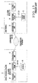
- Fig. 13 is the same as the first embodiment (Fig. 1) described earlier except that the user terminal 5 such as a general PC or telephone containing a communication unit 51 is used in place of the user terminal 1, and that user collation is separately performed in an authentication apparatus (user terminal) 6.
- the user terminal 5 such as a general PC or telephone containing a communication unit 51
- user collation is separately performed in an authentication apparatus (user terminal) 6.
- a collating unit 61, a collation result 61A, a storage circuit 62, a terminal ID 62A, an encryption key 62B, an encryption circuit 63, and communication data 6A in the authentication apparatus 6 correspond to the collating unit 11, the collation result 11A, the storage circuit 12, the terminal ID 12A, the encryption key 12B, the encryption circuit 13, and the communication data 13C, respectively, of the user terminal 1 explained in the first embodiment.
- the communication unit 51 of the user terminal 5 corresponds to the communication unit 14.
- the authentication apparatus 6 has a communication circuit 64 for transmitting output communication data 63C from the encryption circuit 63 as the communication data 6A to the user terminal 5.
- the collating unit 61 performs user collation
- the encryption circuit 63 encrypts the collation result 61A by using the encryption key 62B stored in the storage circuit 62
- the communication circuit 64 transmits the communication data 63C as the communication data 6A to the user terminal 5.
- the communication unit 51 of this user terminal 5 transmits the data as the communication data A.
- Data communication between the authentication apparatus 6 and the user terminal 5 can also be performed by directly connecting the communication circuit 64 of the authentication apparatus 6 and the communication unit 51 of the user terminal 5. It is also possible to give these communication circuit 64 and communication unit 51 a function of performing radio communication to communicate data via a radio zone.
- the authentication apparatus 6 separated from the user terminal is used, so any general apparatus can be used as the user terminal which performs data communication by using a communication network. Since the user need only have the authentication apparatus 6, it is possible to simplify the system and reduce the cost of the system. Also, various services can be used because a general apparatus is used as the user terminal.
- the authentication apparatus 6 can be implemented as a very small apparatus by the use of the technologies (e.g., Japanese Patent Laid-Open No. 2000-242771) of forming a sensor, storage circuit, collating circuit, and the like as a one-chip semiconductor device. This dramatically improves the portability.
- user registered data for use in collation is not output to the outside, so a leak of the registered data for use in collation can be prevented.
- a sensor for detecting biometrical information need not be shared by these users. Therefore, a sensor failure of a certain user has no influence on the other users.
- biometrical information e.g., a fingerprint
- the service providing apparatus 2, the user terminal 1, and the certificate authority 3 in each embodiment described above can be configured using computers.
- the functions of individual units and circuits of each of the service providing apparatus 2, the user terminal 1, and the certificate authority 3 are implemented by cooperatively using these hardware resources and programs (software resources) executed by a microprocessor for controlling the hardware resources.
- These programs can be prerecorded on a recording medium such as a ROM, hard disk, or CD-ROM and loaded into and executed by the microprocessor as needed.
- This collating unit 11 includes a sensor 111, a storage circuit 113, and a collating circuit 115.
- the sensor 111 senses a fingerprint pattern (biometrical information) and outputs the information as sensing data 112.
- the storage circuit 113 stores registered fingerprint data 114 generated beforehand from fingerprint data of a user himself or herself.
- the collating circuit 115 collates the sensing data 112 from the sensor 111 with the registered fingerprint data 114 stored in the storage circuit 113, and outputs a collation result 11A indicating success/failure of authentication of the user in accordance with the degree of matching/mismatching.
- a very small collating unit 11 can be realized by using the technologies (e.g., Japanese Patent Laid-Open No. 2000-242771) of forming these circuits as a one-chip LSI semiconductor device.
- collation data for use in authentication by the collating unit 11 is generated beforehand from a fingerprint data of the user himself or herself by a predetermined registering operation, and registered in the storage circuit 113.
- This sensor 111 includes a plurality of square sensor electrodes 315 of, e.g., 80 ⁇ m side and a lattice-like ground electrode 316 on a dielectric interlayer 314 formed on a lower insulating film 312 on a semiconductor substrate 311 made of, e.g., silicon.
- the plurality of sensor electrodes 315 and the ground electrode 316 are arranged on the same plane defined by the surface of the dielectric interlayer 314.
- the sensor electrodes 315 are formed at intervals of 150 ⁇ m and covered with a passivation film 317 formed on the dielectric interlayer 314.
- the passivation film 317 is formed by an insulator such as polyimide having a relative dielectric constant of about 4.0.
- Each capacitance detection circuit 318 is connected to the sensor electrode 315 by the interconnection 313. This capacitance detection circuit 318 is formed for each sensor electrode 315 and detects a capacitance formed between the sensor electrode 315 and a portion of an object (finger) to be sensed.
- each capacitance detection circuit 318 is connected to the collating circuit 115 and outputs to this collating circuit 115 fingerprint data obtained by converting the capacitance formed in the sensor electrode 315 into a halftone image.
- the capacitance detection circuits 318, the collating circuit 115, and the storage circuit 113 are formed on the semiconductor substrate 311 below the sensor electrodes 315. This makes a one-chip configuration of the collating unit 11 feasible. Another example of this one-chip unit is disclosed in, e.g., Japanese Patent Laid-Open No. 2000-242771.
- Fig. 18 shows a practical configuration of the capacitance detection circuit 318 shown in Fig. 17.
- Reference symbol Cf denotes a capacitance formed between the sensor electrode 315 shown in Fig. 17 and a finger skin 331.
- the sensor 315 forming this capacitance Cf is connected to the drain terminal of an N-channel (Nch) MOS transistor Q3a.
- the source terminal of this transistor Q3a is connected to the input side of a current source 332A of an electric current I.
- a node N1a between the sensor electrode 315 and the transistor Q3a is connected to the source terminal of an Nch MOS transistor (first element) Q2a.
- a node N2a between the drain terminal of this transistor Q2a and the drain terminal of a P-channel (Pch) MOS transistor (first switching means) Q1a is connected to the gate terminal of an Nch MOS transistor Q4a having a drain terminal to which a power supply voltage VDD is applied and a source terminal connected to the ground via a resistor R1.
- An inverter gate 333A is connected to the source terminal of this transistor Q4a.
- Signals PRE and RE are applied to the gate terminals of the transistors Q1a and Q3a, respectively.
- a bias voltage VG is applied from a constant voltage source to the gate terminal of the transistor Q2a.
- Vth denote a gate-source threshold voltage by which the transistor Q2a is turned off, the voltages VDD and VG are so set that VDD > VG - Vth.
- the nodes N1a and N2a have parasitic capacitances Cp1a and Cp2a, respectively.
- the current source 332A and the transistor Q3a construct a signal generation circuit 332.
- the transistor Q4a, the resistor Ra, and the inverter gate 333A construct an output circuit 333.
- Figs. 19A to 19C explain the operation of the capacitance detection circuit 318.
- Fig. 19A shows a potential change of the signal PRE for controlling the transistor Q1a.
- Fig. 19B shows a potential change of the signal RE for controlling the transistor Q3a.
- Fig. 19C shows potential changes at the nodes N1a and N2a.
- the signal PRE of High level (VDD) is applied to the gate terminal of the transistor Q1a, and the signal RE of Low level (GND) is applied to the gate terminal of the transistor Q3a. Accordingly, neither the transistor Q1a nor Q3a is turned on.
- the transistor Q1a When the signal PRE changes from High level to Low level in this state, the transistor Q1a is turned on. In this state, the transistor Q3a is kept OFF, and the signal generation circuit 332 is not in operation. Therefore, the potential of the node N2a is precharged to VDD.
- the node N1a is charged until the gate-source voltage of the transistor Q2a reaches the threshold voltage Vth to turn off this transistor Q2a. Accordingly, the potential of the node N1a is precharged to VG - Vth.
- the transistor Q1a When the signal PRE changes to High level after the precharge is completed, the transistor Q1a is turned off. When the signal RE changes to High level at the same time, the transistor Q3a is turned on, and this renders the signal generation circuit 332 operative.
- ⁇ t denote a period during which the signal RE is High level
- a potential drop ⁇ V at the node N1a after the elapse of ⁇ t is VDD - (VG - Vth) + I ⁇ t/(Cf + Cpla).
- the parasitic capacitance Cp2a is much smaller than the parasitic capacitance Cp1a.
- the potential drop ⁇ V is determined by the value Cf of the capacitance produced between the sensor electrode 315 and the finger surface 331 as an object to be sensed. Since this capacitance value Cf is determined by the distance between the sensor electrode 315 and the finger surface 331, the capacitance value Cf changes in accordance with the ridge/valley of the skin surface. Accordingly, the potential drop ⁇ V changes in accordance with the ridge/valley of the skin surface. Since this potential drop ⁇ V is supplied as an input signal to the output circuit 333, this output circuit 333 receives ⁇ V and outputs a signal reflecting the ridge/valley of the skin surface.
- An output signal from each capacitance detection circuit 318 is supplied as the aforementioned fingerprint image data to the collating circuit 115.
- the collating circuit 115 authenticates the user by collating this fingerprint image data with the registered fingerprint image data prestored in the storage circuit 113.
- the sensor 111, the collating circuit 115, and the storage circuit 113 in the collating unit 11 are formed into one chip.
- the storage circuit 12 in the user terminal 1 will be described below with reference to Fig. 20.
- the storage area 12X stores the registered fingerprint data 12A for use in fingerprint authentication.
- the storage area 12Y stores the user (personal) information (e.g., the name, address, birth date, and credit card number) of the owner of the user terminal.
- the storage area 12Z stores service information (e.g., a password, user terminal identification information, use date/time, coin locker door number, gate opening/closure, concert title, ATM account number, electronic commercial transaction password, telephone directory, and e-mail address) concerning services.
- service information e.g., a password, user terminal identification information, use date/time, coin locker door number, gate opening/closure, concert title, ATM account number, electronic commercial transaction password, telephone directory, and e-mail address
- the user terminal 1 stores only registered fingerprint data and outputs to the outside only the result of authentication of a user himself or herself.
- a configuration like this restricts systems to which this user terminal is applicable.
- the present invention includes a certificate authority which, in response to a request for certification of the validity of a collation result transmitted from a user terminal across a communication network, certifies the validity of the collation result and notifies a certificate including this collation result across the communication network.
- the user terminal identifies a user himself or herself by collation by using biometrical information of the user, and notifies a service providing apparatus of this collation result across the communication network.
- the service providing apparatus requests across the communication network the certificate authority to certify the validity of the collation result. If the validity of the collation result is certified by a certificate notified from the certificate authority, the service providing apparatus provides a predetermined service to the user on the basis of the collation result contained in the certificate.
- the certificate authority as a third party checks and authenticates the validity of the collation result. Consequently, high safety can be obtained.
- the certificate authority can be readily shared by a plurality of user terminals and a plurality of service providing apparatuses. Therefore, high-level security can be obtained without increasing the system scale and the maintenance cost.
Landscapes
- Engineering & Computer Science (AREA)
- Computer Security & Cryptography (AREA)
- Computer Hardware Design (AREA)
- Computing Systems (AREA)
- General Engineering & Computer Science (AREA)
- Computer Networks & Wireless Communication (AREA)
- Signal Processing (AREA)
- Health & Medical Sciences (AREA)
- Biomedical Technology (AREA)
- General Health & Medical Sciences (AREA)
- Management, Administration, Business Operations System, And Electronic Commerce (AREA)
Applications Claiming Priority (2)
| Application Number | Priority Date | Filing Date | Title |
|---|---|---|---|
| JP2001107173 | 2001-04-05 | ||
| JP2001107173 | 2001-04-05 |
Publications (3)
| Publication Number | Publication Date |
|---|---|
| EP1248437A2 true EP1248437A2 (de) | 2002-10-09 |
| EP1248437A3 EP1248437A3 (de) | 2004-07-07 |
| EP1248437B1 EP1248437B1 (de) | 2007-11-21 |
Family
ID=18959534
Family Applications (1)
| Application Number | Title | Priority Date | Filing Date |
|---|---|---|---|
| EP02090132A Expired - Lifetime EP1248437B1 (de) | 2001-04-05 | 2002-04-05 | Netzwerkauthentifizierungssystem, Verfahren, Programm, Bereitstellungsvorrichtung, Zertifikatsautorität und Benutzerendgerät |
Country Status (3)
| Country | Link |
|---|---|
| US (1) | US7254711B2 (de) |
| EP (1) | EP1248437B1 (de) |
| DE (1) | DE60223617T2 (de) |
Cited By (1)
| Publication number | Priority date | Publication date | Assignee | Title |
|---|---|---|---|---|
| KR100529550B1 (ko) * | 2001-10-18 | 2005-11-22 | 한국전자통신연구원 | 공개키 기반 구조 인증시스템에서 생체정보를 이용한인증서 권한 변경 방법 |
Families Citing this family (18)
| Publication number | Priority date | Publication date | Assignee | Title |
|---|---|---|---|---|
| US7961884B2 (en) * | 2002-08-13 | 2011-06-14 | Ipass Inc. | Method and system for changing security information in a computer network |
| EP1429224A1 (de) * | 2002-12-10 | 2004-06-16 | Texas Instruments Incorporated | Firmware Laufzeit Authentisierung |
| US20050086468A1 (en) * | 2003-10-17 | 2005-04-21 | Branislav Meandzija | Digital certificate related to user terminal hardware in a wireless network |
| US7430606B1 (en) | 2003-10-17 | 2008-09-30 | Arraycomm, Llc | Reducing certificate revocation lists at access points in a wireless access network |
| JP2006155196A (ja) * | 2004-11-29 | 2006-06-15 | Intelligentdisc Inc | ネットワークアクセスシステム、方法及び記憶媒体 |
| WO2006068071A1 (ja) * | 2004-12-20 | 2006-06-29 | Intelligentdisc, Inc. | ネットワーク情報保護方法及び記憶媒体 |
| JP4514134B2 (ja) * | 2005-01-24 | 2010-07-28 | 株式会社コナミデジタルエンタテインメント | ネットワークシステム、サーバ装置、不正利用検出方法、ならびに、プログラム |
| US20060235804A1 (en) * | 2005-04-18 | 2006-10-19 | Sharp Kabushiki Kaisha | Service providing system, service using device, service proving device, service relaying device, method for performing authentication, authentication program, and recording medium thereof |
| US8661262B2 (en) * | 2005-08-18 | 2014-02-25 | Nec Corporation | User authentication system, terminal used in the same, authentication verification device, and program |
| ITUD20050209A1 (it) * | 2005-12-09 | 2007-06-10 | Eurotech Spa | Metodo per l'individuazione di affinita' tra soggetti e relativo apparato |
| JP4224084B2 (ja) * | 2006-06-26 | 2009-02-12 | 株式会社東芝 | 通信制御装置、通信制御方法および通信制御プログラム |
| US9830278B1 (en) * | 2008-03-06 | 2017-11-28 | EMC IP Holding Company LLC | Tracking replica data using key management |
| US8892869B2 (en) * | 2008-12-23 | 2014-11-18 | Avaya Inc. | Network device authentication |
| US9077544B2 (en) * | 2009-09-15 | 2015-07-07 | Welch Allyn, Inc. | Automatic provisioning of authentication credentials |
| US10484373B2 (en) | 2017-04-11 | 2019-11-19 | Mastercard International Incorporated | Systems and methods for biometric authentication of certificate signing request processing |
| US10659483B1 (en) * | 2017-10-31 | 2020-05-19 | EMC IP Holding Company LLC | Automated agent for data copies verification |
| US10664619B1 (en) | 2017-10-31 | 2020-05-26 | EMC IP Holding Company LLC | Automated agent for data copies verification |
| US20220166762A1 (en) * | 2020-11-25 | 2022-05-26 | Microsoft Technology Licensing, Llc | Integrated circuit for obtaining enhanced privileges for a network-based resource and performing actions in accordance therewith |
Family Cites Families (17)
| Publication number | Priority date | Publication date | Assignee | Title |
|---|---|---|---|---|
| JPS6353099A (ja) | 1986-08-22 | 1988-03-07 | 日立東京エレクトロニクス株式会社 | 識別カ−ドおよびそのカ−ドを用いる識別方式 |
| US5280527A (en) | 1992-04-14 | 1994-01-18 | Kamahira Safe Co., Inc. | Biometric token for authorizing access to a host system |
| US6230148B1 (en) * | 1994-11-28 | 2001-05-08 | Veristar Corporation | Tokenless biometric electric check transaction |
| US6105010A (en) * | 1997-05-09 | 2000-08-15 | Gte Service Corporation | Biometric certifying authorities |
| US6202151B1 (en) * | 1997-05-09 | 2001-03-13 | Gte Service Corporation | System and method for authenticating electronic transactions using biometric certificates |
| AU7484898A (en) * | 1997-05-09 | 1998-11-27 | Gte Government Systems Corporation | Biometric certificates |
| JP3736059B2 (ja) | 1997-08-20 | 2006-01-18 | 松下電器産業株式会社 | ジャー炊飯器 |
| DE19811332A1 (de) * | 1998-03-16 | 1999-09-23 | Giesecke & Devrient Gmbh | Verfahren und Vorrichtung zur Prüfung eines biometrischen Merkmals |
| JP2000047990A (ja) | 1998-08-03 | 2000-02-18 | Hitachi Ltd | 本人認証システム利用者登録方法 |
| JP2000092046A (ja) | 1998-09-11 | 2000-03-31 | Mitsubishi Electric Corp | 遠隔認証システム |
| JP3490350B2 (ja) | 1999-08-30 | 2004-01-26 | 沖電気工業株式会社 | 電子決済システム |
| US20010034836A1 (en) * | 2000-01-31 | 2001-10-25 | Netmarks Inc. | System for secure certification of network |
| US6854056B1 (en) * | 2000-09-21 | 2005-02-08 | International Business Machines Corporation | Method and system for coupling an X.509 digital certificate with a host identity |
| US20020095588A1 (en) * | 2001-01-12 | 2002-07-18 | Satoshi Shigematsu | Authentication token and authentication system |
| US20030101349A1 (en) * | 2001-11-26 | 2003-05-29 | Po-Tong Wang | Method of using cryptography with biometric verification on security authentication |
| GB2391681B (en) * | 2002-08-01 | 2005-09-21 | Ncr Int Inc | Self-service terminal |
| JP2005100062A (ja) * | 2003-09-24 | 2005-04-14 | Sanyo Electric Co Ltd | 認証装置および認証方法 |
-
2002
- 2002-04-04 US US10/117,727 patent/US7254711B2/en not_active Expired - Fee Related
- 2002-04-05 EP EP02090132A patent/EP1248437B1/de not_active Expired - Lifetime
- 2002-04-05 DE DE60223617T patent/DE60223617T2/de not_active Expired - Lifetime
Cited By (1)
| Publication number | Priority date | Publication date | Assignee | Title |
|---|---|---|---|---|
| KR100529550B1 (ko) * | 2001-10-18 | 2005-11-22 | 한국전자통신연구원 | 공개키 기반 구조 인증시스템에서 생체정보를 이용한인증서 권한 변경 방법 |
Also Published As
| Publication number | Publication date |
|---|---|
| EP1248437B1 (de) | 2007-11-21 |
| DE60223617D1 (de) | 2008-01-03 |
| US20020152375A1 (en) | 2002-10-17 |
| DE60223617T2 (de) | 2008-10-23 |
| EP1248437A3 (de) | 2004-07-07 |
| US7254711B2 (en) | 2007-08-07 |
Similar Documents
| Publication | Publication Date | Title |
|---|---|---|
| EP1248437B1 (de) | Netzwerkauthentifizierungssystem, Verfahren, Programm, Bereitstellungsvorrichtung, Zertifikatsautorität und Benutzerendgerät | |
| US6310966B1 (en) | Biometric certificates | |
| US7447910B2 (en) | Method, arrangement and secure medium for authentication of a user | |
| CA2417770C (en) | Trusted authentication digital signature (tads) system | |
| US8340296B2 (en) | Method and system for registering and verifying smart card certificate for users moving between public key infrastructure domains | |
| KR100449484B1 (ko) | 공개키 기반 구조 인증시스템에서 생체정보를 이용한인증서 발급 방법 | |
| US20040044625A1 (en) | Digital contents issuing system and digital contents issuing method | |
| KR20030074483A (ko) | 서비스 제공자 장치로부터 네트워크를 통하여 서비스이용자 장치에 서비스를 제공하는 서비스 제공 시스템 | |
| JP2002278942A (ja) | ユーザ認証システム、ユーザ端末装置、サービス提供装置及び認証装置 | |
| JP3860721B2 (ja) | 認証システム | |
| JP5107885B2 (ja) | 個人情報提供装置、個人情報提供方法 | |
| JP2002269051A (ja) | ユーザ認証方法及びユーザ認証システム | |
| JP2002368737A (ja) | ネットワーク認証システムおよび方法ならびにプログラム、サービス提供装置、認証局、ユーザ端末 | |
| JP2013020643A (ja) | 個人情報提供装置、および個人情報提供方法 | |
| JP2002278939A (ja) | ユーザ認証方法、ユーザ認証システム、認証装置及びサービス提供装置 | |
| JP2002281028A (ja) | 認証システムおよび方法、記録媒体、プログラム | |
| US20220255925A1 (en) | Cryptobionic system and associated devices and methods | |
| JP3825271B2 (ja) | ゲート開閉システム | |
| KR20070082833A (ko) | 휴대형 성문-잠금 원격 전송 시스템 및 관련 동작 방법 | |
| US11860992B1 (en) | Authentication and authorization for access to soft and hard assets | |
| US20240137354A1 (en) | Secure online authentication method using mobile id document | |
| JP2002314531A (ja) | 電子データ記録再生装置および方法 | |
| JP2002298202A (ja) | 生体情報認証自動現金受け払い機 | |
| JP4545480B2 (ja) | 電子署名生成装置、ウェブサーバ、生体情報認証装置、及びユーザ認証システム | |
| JP2002312322A (ja) | 生体情報認証トークン |
Legal Events
| Date | Code | Title | Description |
|---|---|---|---|
| PUAI | Public reference made under article 153(3) epc to a published international application that has entered the european phase |
Free format text: ORIGINAL CODE: 0009012 |
|
| AK | Designated contracting states |
Kind code of ref document: A2 Designated state(s): AT BE CH CY DE DK ES FI FR GB GR IE IT LI LU MC NL PT SE TR |
|
| AX | Request for extension of the european patent |
Free format text: AL;LT;LV;MK;RO;SI |
|
| RTI1 | Title (correction) |
Free format text: NETWORK AUTHENTICATION SYSTEM, METHOD, PROGRAM, SERVICE PROVIDING APPARATUS, CERTIFICATE AUTHORITY, AND USER TERMINAL |
|
| PUAL | Search report despatched |
Free format text: ORIGINAL CODE: 0009013 |
|
| AK | Designated contracting states |
Kind code of ref document: A3 Designated state(s): AT BE CH CY DE DK ES FI FR GB GR IE IT LI LU MC NL PT SE TR |
|
| AX | Request for extension of the european patent |
Extension state: AL LT LV MK RO SI |
|
| 17P | Request for examination filed |
Effective date: 20040712 |
|
| 17Q | First examination report despatched |
Effective date: 20041006 |
|
| AKX | Designation fees paid |
Designated state(s): DE FR GB |
|
| 17Q | First examination report despatched |
Effective date: 20041006 |
|
| GRAP | Despatch of communication of intention to grant a patent |
Free format text: ORIGINAL CODE: EPIDOSNIGR1 |
|
| GRAS | Grant fee paid |
Free format text: ORIGINAL CODE: EPIDOSNIGR3 |
|
| GRAA | (expected) grant |
Free format text: ORIGINAL CODE: 0009210 |
|
| AK | Designated contracting states |
Kind code of ref document: B1 Designated state(s): DE FR GB |
|
| REG | Reference to a national code |
Ref country code: GB Ref legal event code: FG4D |
|
| REF | Corresponds to: |
Ref document number: 60223617 Country of ref document: DE Date of ref document: 20080103 Kind code of ref document: P |
|
| ET | Fr: translation filed | ||
| PLBE | No opposition filed within time limit |
Free format text: ORIGINAL CODE: 0009261 |
|
| STAA | Information on the status of an ep patent application or granted ep patent |
Free format text: STATUS: NO OPPOSITION FILED WITHIN TIME LIMIT |
|
| 26N | No opposition filed |
Effective date: 20080822 |
|
| PGFP | Annual fee paid to national office [announced via postgrant information from national office to epo] |
Ref country code: GB Payment date: 20130306 Year of fee payment: 12 |
|
| PGFP | Annual fee paid to national office [announced via postgrant information from national office to epo] |
Ref country code: DE Payment date: 20130429 Year of fee payment: 12 |
|
| PGFP | Annual fee paid to national office [announced via postgrant information from national office to epo] |
Ref country code: FR Payment date: 20130426 Year of fee payment: 12 |
|
| REG | Reference to a national code |
Ref country code: DE Ref legal event code: R119 Ref document number: 60223617 Country of ref document: DE |
|
| GBPC | Gb: european patent ceased through non-payment of renewal fee |
Effective date: 20140405 |
|
| REG | Reference to a national code |
Ref country code: DE Ref legal event code: R119 Ref document number: 60223617 Country of ref document: DE Effective date: 20141101 |
|
| REG | Reference to a national code |
Ref country code: FR Ref legal event code: ST Effective date: 20141231 |
|
| PG25 | Lapsed in a contracting state [announced via postgrant information from national office to epo] |
Ref country code: DE Free format text: LAPSE BECAUSE OF NON-PAYMENT OF DUE FEES Effective date: 20141101 Ref country code: GB Free format text: LAPSE BECAUSE OF NON-PAYMENT OF DUE FEES Effective date: 20140405 |
|
| PG25 | Lapsed in a contracting state [announced via postgrant information from national office to epo] |
Ref country code: FR Free format text: LAPSE BECAUSE OF NON-PAYMENT OF DUE FEES Effective date: 20140430 |