EP1248137A2 - Laser beam irradiation device with changeable spreading angle - Google Patents
Laser beam irradiation device with changeable spreading angle Download PDFInfo
- Publication number
- EP1248137A2 EP1248137A2 EP02252134A EP02252134A EP1248137A2 EP 1248137 A2 EP1248137 A2 EP 1248137A2 EP 02252134 A EP02252134 A EP 02252134A EP 02252134 A EP02252134 A EP 02252134A EP 1248137 A2 EP1248137 A2 EP 1248137A2
- Authority
- EP
- European Patent Office
- Prior art keywords
- laser beam
- cylindrical lens
- prism
- irradiation device
- center line
- Prior art date
- Legal status (The legal status is an assumption and is not a legal conclusion. Google has not performed a legal analysis and makes no representation as to the accuracy of the status listed.)
- Granted
Links
Images
Classifications
-
- G—PHYSICS
- G02—OPTICS
- G02B—OPTICAL ELEMENTS, SYSTEMS OR APPARATUS
- G02B27/00—Optical systems or apparatus not provided for by any of the groups G02B1/00 - G02B26/00, G02B30/00
- G02B27/09—Beam shaping, e.g. changing the cross-sectional area, not otherwise provided for
-
- Y—GENERAL TAGGING OF NEW TECHNOLOGICAL DEVELOPMENTS; GENERAL TAGGING OF CROSS-SECTIONAL TECHNOLOGIES SPANNING OVER SEVERAL SECTIONS OF THE IPC; TECHNICAL SUBJECTS COVERED BY FORMER USPC CROSS-REFERENCE ART COLLECTIONS [XRACs] AND DIGESTS
- Y10—TECHNICAL SUBJECTS COVERED BY FORMER USPC
- Y10S—TECHNICAL SUBJECTS COVERED BY FORMER USPC CROSS-REFERENCE ART COLLECTIONS [XRACs] AND DIGESTS
- Y10S33/00—Geometrical instruments
- Y10S33/21—Geometrical instruments with laser
Definitions
- the present invention relates to a laser beam irradiation device for irradiating a fan-shaped laser beam, and in particular, to a laser beam irradiation device by which it is possible to change a spreading angle of the fan-shaped laser beam irradiated from the device.
- a method for projecting a fan-shaped laser beam has been known. According to this method, a diverging light beam emitted from a laser light source passes through a cylindrical lens, and a luminous flux of a laser beam is turned to a fan-like shape by refractive power caused by a curved surface of the cylindrical lens.
- the fan-shaped laser beam provided by a conventional type laser beam irradiation device
- the diverging light passes through the cylindrical lens.
- the fan-shaped laser beam projected by the conventional type laser beam irradiation device is very useful for the application at a near distance.
- the fan-shaped laser beam is spread widely and luminance is decreased.
- the thickness of the fan-shaped laser beam is increased, and inconveniences arise practically when it is used for forming a reference line.
- the spreading angle is fixed in the conventional case. For instance, when a larger spreading angle is required for the application at a near distance or when there is a request to reduce the spreading angle for the application at a long distance, the conventional type device cannot meet the requirements.
- the laser beam irradiation device comprises a light source for emitting a laser beam, a cylindrical lens, an optical system for entering the laser beam to the cylindrical lens perpendicularly with respect to a center line of the cylindrical lens, and a luminous flux rotating means for rotating the incident laser beam around an optical axis of the laser beam.
- the present invention provides the laser beam irradiation device as described above, wherein the optical system comprises a condenser lens for entering a parallel flux to the cylindrical lens.
- the present invention provides the laser beam irradiation device as described above, wherein the optical system enters the laser beam to the cylindrical lens perpendicularly with respect to the center line after the laser beam passes through the cylindrical lens in parallel to the center line of the cylindrical lens, and wherein the optical system comprises a comer cube prism and a pentagonal prism.
- the present invention provides the laser beam irradiation device as described above, wherein the optical system comprises a rhombic prism for moving the optical axis in a parallel direction, and a pentagonal prism for entering the laser beam projected from the rhombic prism to the cylindrical lens perpendicularly with respect to the center line.
- the present invention provides the laser beam irradiation device as described above, wherein the luminous flux rotating means is designed in such manner that the prism holder for holding the optical system is rotated around the center line of the cylindrical lens.
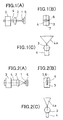
- Fig. 1 and Fig. 2 each represents a basic block diagram of a device according to the present invention.
- Fig. 1 (A) and Fig. 2 (A) each represents a side view
- Fig. 1 (B) and Fig. 2 (B) each represents a front view
- Fig. 1 (C) and Fig. 2 (C) each represents a plane view.
- reference numeral 1 denotes a laser light source, e.g. a semiconductor laser
- 2 is a condenser lens which turns the laser beam from the laser light source 1 to a laser beam which has a parallel flux
- 3 is a cylindrical lens
- 4 is a laser beam irradiated from the laser light source 1
- 6 is a luminous flux rotating means, which can rotate the luminous flux of the laser beam emitted from the laser light source 1 at an angle of 90° around an optical axis of the luminous flux.
- a cross-section of the luminous flux of the laser beam 4 emitted from the semiconductor laser is in an elliptical shape. For this reason, a cross-section of the luminous flux of the laser beam 4 which has been turned to the parallel flux by the condenser lens 2 is also in an elliptical shape.
- the laser beam 4 is entered to the cylindrical lens 3 so that a longer axis 8 of the cross-section of the luminous flux crosses perpendicularly to a center line 7 of the cylindrical lens 3.
- the luminous flux of the laser beam 4 is rotated by the luminous flux rotating means 6 at an angle of 90° around the optical axis of the luminous flux and the laser beam is entered so that a longer axis 8 of the cross-section of the luminous flux runs in parallel to or is aligned with the center line 7 of the cylindrical lens 3.
- the laser beam 4, which has passed through the cylindrical lens 3, is projected as a fan-shaped laser beam 4a.
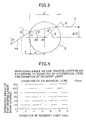
- Fig. 3 is a drawing to show relationship between the luminous flux of the laser beam 4 entering the cylindrical lens 3 and the spreading angle of the luminous flux of the fan-shaped laser beam 4a after it has passed through the cylindrical lens 3.
- a diameter of the cylindrical lens 3 is d
- a radius of the incident luminous flux of the laser beam 4 is d'/2
- a refractive index of the cylindrical lens 3 is n
- the spreading angle (half-value) of the luminous flux of the fan-shaped laser beam 4a after it has passed through the cylindrical lens 3 is ⁇ .
- a refractive angle ⁇ ' of the optical axis of the light entering the cylindrical lens 3 after it has entered the cylindrical lens 3 can be given by the following equation (2).
- ⁇ ' sin -1 (1/n' ⁇ sin ⁇ )
- the spreading angle ⁇ (half-value) of the fan-shaped laser beam 4a after it has passed through the cylindrical lens 3 can be given by the following equation (3).
- ⁇ 2 ⁇ - 2 ⁇ '
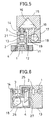
- a light source unit holder 13 in a cylindrical shape is rotatably mounted on a base 11 via rotation bearings 12.
- the laser light source 1 using a semiconductor laser as a light source is provided inside the light source unit holder 13, the laser light source 1 using a semiconductor laser as a light source is provided inside the light source unit holder 13, the laser light source 1 using a semiconductor laser as a light source is provided.
- the condenser lens 2 is arranged on the optical axis of the laser light source 1, and the cylindrical lens 3 is disposed so that its center line is aligned with the optical axis.
- the condenser lens 2 turns the laser beam 4 from the laser light source 1 to a laser beam which has a parallel flux. End surfaces of the cylindrical lens 3 are positioned perpendicularly to the optical axis, and the laser beam 4 advances straightly through the cylindrical lens 3.
- a corner prism holder 15 is rotatably mounted via a hollow shaft 14, and a corner cube prism 16 is held on the corner prism holder 15.
- a pentagonal prism holder 17 is fixed, and a pentagonal prism 18 is held by the pentagonal prism holder 17.
- An optical path hole 19 is formed in the corner prism holder 15 and the pentagonal prism holder 17, and the laser beam 4 entering and reflected by the corner cube prism 16 and the pentagonal prism 18 passes through the optical path hole 19.
- the laser beam 4 from the laser light source 1 is turned to a laser beam which has a parallel flux by the condenser lens 2.
- the laser beam 4 is reflected by the corner cube prism 16 so that the laser beam 4 run in parallel to the incident light. Further, the beam is deflected in a perpendicular direction (horizontal direction) by the pentagonal prism 18. Therefore, the laser beam 4 from the laser light source 1 enters the cylindrical lens 3 in a direction perpendicular to the center line 7.
- the light source unit holder 13 holds the cylindrical lens 3 with a gap 21, and it allows the reflected laser beam from the pentagonal prism 18 to pass so that the laser beam crosses perpendicularly the center line of the cylindrical lens 3.
- the laser beam 4 emitted from the laser light source 1 passes through the cylindrical lens 3 without changing the optical axis. Then, the laser beam enters the corner cube prism 16 and is reflected.
- the corner cube prism 16 reflects the laser beam 4 in such manner that the exit light optical axis is to be in parallel to the incident light optical axis.
- the laser beam 4 reflected by the corner cube prism 16 passes through the optical path hole 19 and enters the pentagonal prism 18.
- the pentagonal prism 18 reflects the laser beam 4 by maintaining a right-angle direction with respect to the incident light optical axis regardless of incident angle of the incident light optical axis. More strictly, when the pentagonal prism 18 is tilted in a perpendicular direction with respect to the paper surface in Fig. 5, perpendicular crossing of the reflection light optical axis will be lost, while this is negligible value when the tilt angle of the pentagonal prism 18 is very small.
- the corner prism holder 15 which holds the corner cube prism 16 and the pentagonal prism 18, is rotatable via the shaft 14. However, when it is rotated, deflection of the shaft 14 unavoidably occurs. As a result, the laser beam 4 always enters the pentagonal prism 18 at a deflected angle.
- the laser beam 4 passing through the cylindrical lens 3 in the direction of the optical axis can be directed perpendicularly to the center line 7 of the cylindrical lens 3 without being influenced by the deflection of the shaft 14. This makes it possible to prevent the tilting of the fan-shaped laser beam 4a.
- the condition of the luminous flux of the laser beam 4 with respect to the cylindrical lens 3 under the status shown in Fig. 5 is the condition shown in Fig. 1, for instance.
- the fan-shaped laser beam 4a has a wider spreading angle and this is suitable for an application to form a reference line, etc. at a near distance. Because the laser beam 4 has a parallel flux, the beam is not spread in the thickness direction.
- the corner prism holder 15 is continuously rotated up to an angle of 90° around the shaft 14.
- the condition of the luminous flux of the laser beam 4 entering the cylindrical lens 3 is such that the longer axis 8 of the cross-section of the luminous flux is aligned with the center line 7 of the cylindrical lens 3 as shown in Fig. 2. Therefore, the spreading angle of the projected fan-shaped laser beam 4a is decreased. That is, by rotating the corner prism holder 15, it is possible to change the spreading angle of the fan-shaped laser beam 4a.
- the corner prism holder 15 is also rotated together.
- the laser beam 4 is a parallel flux and it is not spread in the thickness direction, i.e. in the direction of its thickness, and the thickness is equalized with the length of the longer axis of the luminous flux cross-section.
- the luminous flux is not large, but the value of largeness is enough for practical use.
- the spreading angle of the fan-shaped laser beam 4a is at the largest. In the condition shown in Fig. 2, the spreading angle of the fan-shaped laser beam 4a is at the smallest.
- the thickness of the luminous flux of the fan-shaped laser beam 4a is between the length of the longer axis and the length of the shorter axis of the cross-section of the luminous flux of the laser beam 4.
- a spreading angle adjusting motor (not shown) may be provided on the base 11 or on the light source unit holder 13. If the corner prism holder 15 is rotated via a train of gears, it is possible to set an accurate angle. Further, if it is designed to be driven via a control unit provided with a spreading angle adjusting motor communication function, the spreading angle can be adjusted by remote control.
- the laser light source 1 having an optical axis in a horizontal direction is provided on the light source unit holder 13, and the condenser lens 2 is arranged on the optical axis.
- An arm 25 with a hook shape is extended in a horizontal direction from the light source unit holder 13, and the cylindrical lens 3 is retained at a horizontal position on the arm 25.
- a prism holder 26 is rotatably arranged on the arm 25 via the shaft 14 so that it can be rotated at least at an angle of 90°.
- the center line of the shaft 14 is aligned with the center line 7 of the cylindrical lens 3.
- the prism holder 26 holds a rhombic prism 27 and the pentagonal prism 18.
- the rhombic prism 27 reflects the laser beam 4 coming from the laser light source 1 on both end surfaces in parallel, and this prism moves the laser beam 4 while maintaining the exit light optical axis in parallel to the incident light optical axis of the laser beam 4, and the laser beam 4 is guided toward the pentagonal prism 18.
- the pentagonal prism 18 deflects the incident light optical axis in a perpendicular direction and the laser beam enters the cylindrical lens 3. From the cylindrical lens 3, the fan-shaped laser beam 4a spreading in a vertical direction is projected.
- tilting of the pentagonal prism 18 occurs due to deflection of the shaft 14.
- the accuracy of the shaft is increased, only the negligible error occurs in practical application.
- the prism holder comprising the corner prism holder 15 and the pentagonal prism holder 17 is not uniformly arranged with respect to the shaft 14. For this reason, when the laser beam 4 is projected in a vertical direction, for instance, the shaft is very likely to be deflected if the device is tilted at an angle of 90°.
- the rhombic prism 27 is used instead of the corner prism 16, and the space required can be reduced. Thus, the balance of the rotating prism holder 26 can be more equalized with respect to the shaft 14.
- the present variation is designed in such a structure that the laser beam 4 does not pass through the cylindrical lens 3, and no high accuracy is required on both end surfaces of the cylindrical lens 3.
- the laser beam irradiation device comprises a light source for emitting a laser beam, a cylindrical lens, an optical system for entering the laser beam to the cylindrical lens perpendicularly with respect to a center line of the cylindrical lens, and a luminous flux rotating means for rotating the incident laser beam around an optical axis of the laser beam. Because the spreading angle of the fan-shaped laser beam can be changed by the rotation of the laser beam, it is possible to project the fan-shaped laser beam with high luminance for the application in the range from a near distance to a long distance.
Landscapes
- Physics & Mathematics (AREA)
- General Physics & Mathematics (AREA)
- Optics & Photonics (AREA)
- Laser Beam Processing (AREA)
- Semiconductor Lasers (AREA)
- Mechanical Light Control Or Optical Switches (AREA)
- Radiation-Therapy Devices (AREA)
- Mechanical Optical Scanning Systems (AREA)
Abstract
Description
Claims (5)
- A laser beam irradiation device, comprising a light source for emitting a laser beam, a cylindrical lens, an optical system for entering the laser beam to said cylindrical lens perpendicularly with respect to a center line of said cylindrical lens, and a luminous flux rotating means for rotating the incident laser beam around an optical axis of the laser beam.
- A laser beam irradiation device according to claim 1, wherein said optical system comprises a condenser lens for entering a parallel flux to said cylindrical lens.
- A laser beam irradiation device according to claim 1, wherein said optical system enters the laser beam to said cylindrical lens perpendicularly with respect to said center line after the laser beam passes through said cylindrical lens in parallel to the center line of said cylindrical lens, and wherein said optical system comprises a corner cube prism and a pentagonal prism.
- A laser beam irradiation device according to claim 1, wherein said optical system comprises a rhombic prism for moving the optical axis in a parallel direction, and a pentagonal prism for entering the laser beam projected from said rhombic prism to said cylindrical lens perpendicularly with respect to the center line.
- A laser beam irradiation device according to claim 1, wherein the luminous flux rotating means is designed in such manner that said prism holder for holding said optical system is rotated around the center line of said cylindrical lens.
Applications Claiming Priority (2)
| Application Number | Priority Date | Filing Date | Title |
|---|---|---|---|
| JP2001094004A JP4614565B2 (en) | 2001-03-28 | 2001-03-28 | Laser beam irradiation device |
| JP2001094004 | 2001-03-28 |
Publications (3)
| Publication Number | Publication Date |
|---|---|
| EP1248137A2 true EP1248137A2 (en) | 2002-10-09 |
| EP1248137A3 EP1248137A3 (en) | 2005-01-05 |
| EP1248137B1 EP1248137B1 (en) | 2007-01-10 |
Family
ID=18948271
Family Applications (1)
| Application Number | Title | Priority Date | Filing Date |
|---|---|---|---|
| EP02252134A Expired - Lifetime EP1248137B1 (en) | 2001-03-28 | 2002-03-25 | Laser beam irradiation device with changeable spreading angle |
Country Status (4)
| Country | Link |
|---|---|
| US (1) | US6679609B2 (en) |
| EP (1) | EP1248137B1 (en) |
| JP (1) | JP4614565B2 (en) |
| DE (1) | DE60217433T2 (en) |
Cited By (1)
| Publication number | Priority date | Publication date | Assignee | Title |
|---|---|---|---|---|
| WO2006046495A1 (en) | 2004-10-27 | 2006-05-04 | Semiconductor Energy Laboratory Co., Ltd. | Beam homogenizer, and laser irradiation method, laser irradiation apparatus, and laser annealing method of non-single crystalline semiconductor film using the same |
Families Citing this family (18)
| Publication number | Priority date | Publication date | Assignee | Title |
|---|---|---|---|---|
| JP3821712B2 (en) * | 2001-12-28 | 2006-09-13 | 株式会社トプコン | Line laser equipment |
| US6892464B2 (en) * | 2002-03-13 | 2005-05-17 | Kabushiki Kaisha Topcon | Laser sighting device |
| US7624528B1 (en) | 2002-05-18 | 2009-12-01 | John Curtis Bell | Scope adjustment method and apparatus |
| US6886287B1 (en) | 2002-05-18 | 2005-05-03 | John Curtis Bell | Scope adjustment method and apparatus |
| US8468930B1 (en) | 2002-05-18 | 2013-06-25 | John Curtis Bell | Scope adjustment method and apparatus |
| US9310165B2 (en) | 2002-05-18 | 2016-04-12 | John Curtis Bell | Projectile sighting and launching control system |
| US6856470B2 (en) * | 2002-08-26 | 2005-02-15 | Hitachi Koki Co., Ltd. | Rod lens and laser marking apparatus |
| US20040221470A1 (en) * | 2003-05-09 | 2004-11-11 | Index Measuring Tape Co., Ltd. | Tape rule having laser indicating mechanism |
| JP4282432B2 (en) | 2003-10-14 | 2009-06-24 | 株式会社トプコン | Light receiving device for rotary laser device |
| USD508938S1 (en) | 2003-11-07 | 2005-08-30 | Black & Decker Inc. | Tripod |
| USD505442S1 (en) | 2003-11-07 | 2005-05-24 | Black & Decker Inc. | Folding laser tripod |
| USD509527S1 (en) | 2003-11-07 | 2005-09-13 | Black & Decker Inc. | Stored tripod |
| USD509180S1 (en) | 2003-11-07 | 2005-09-06 | Black & Decker Inc. | Laser head |
| US7021114B2 (en) * | 2004-04-16 | 2006-04-04 | Boston Scientific Scimed, Inc. | Stent crimper |
| US7497019B2 (en) | 2005-08-04 | 2009-03-03 | Irwin Industrial Tool Company | Laser reference device |
| US7328516B2 (en) * | 2005-08-05 | 2008-02-12 | Irwin Industrial Tool Company | Laser level |
| DE102007055439A1 (en) * | 2007-11-21 | 2009-05-28 | Hilti Aktiengesellschaft | Rotary laser with remote control |
| CN103791893A (en) * | 2014-02-12 | 2014-05-14 | 浙江合波光学科技有限公司 | Multipoint laser module and laser dotting apparatus |
Family Cites Families (15)
| Publication number | Priority date | Publication date | Assignee | Title |
|---|---|---|---|---|
| JP3073994B2 (en) * | 1988-08-11 | 2000-08-07 | 株式会社モリタ製作所 | Variable irradiation angle laser irradiation device |
| JP2564963B2 (en) * | 1990-03-29 | 1996-12-18 | 三菱電機株式会社 | Target and three-dimensional position and orientation measurement system using the target |
| US5140608A (en) * | 1991-05-29 | 1992-08-18 | Optrotech Ltd, Israel Company | Optical system for focusing a light beam on to an image plane |
| US5838431A (en) * | 1996-01-16 | 1998-11-17 | Asahi Kogaku Kogyo Kabushiki Kaisha | Laser marking device |
| JP3917231B2 (en) * | 1996-02-06 | 2007-05-23 | 株式会社半導体エネルギー研究所 | Laser irradiation apparatus and laser irradiation method |
| JP3330881B2 (en) * | 1996-02-13 | 2002-09-30 | 株式会社半導体エネルギー研究所 | Laser irradiation equipment |
| JP3731022B2 (en) * | 1997-04-04 | 2006-01-05 | 株式会社トプコン | Rotating laser device |
| JPH11101642A (en) * | 1997-09-29 | 1999-04-13 | Asahi Optical Co Ltd | Beam image horizontal adjustment method and beam image horizontal adjustment device |
| JPH11142780A (en) * | 1997-11-12 | 1999-05-28 | Mitsubishi Electric Corp | Light source device and projection display device |
| JP4159153B2 (en) * | 1998-12-03 | 2008-10-01 | 株式会社トプコン | Rotating laser device and light receiving device |
| US6399940B1 (en) * | 1999-05-10 | 2002-06-04 | Fanuc America Corporation | Optical rotary position encoder |
| JP2000202673A (en) * | 2000-01-01 | 2000-07-25 | Semiconductor Energy Lab Co Ltd | Laser irradiation device |
| DE60120079T8 (en) * | 2000-10-31 | 2007-06-28 | Dainippon Screen Mfg. Co., Ltd. | Laser irradiation device and image recorder |
| JP4712212B2 (en) * | 2001-03-28 | 2011-06-29 | 株式会社トプコン | Laser sighting device |
| JP4870283B2 (en) * | 2001-07-13 | 2012-02-08 | 株式会社トプコン | Laser sighting device |
-
2001
- 2001-03-28 JP JP2001094004A patent/JP4614565B2/en not_active Expired - Fee Related
-
2002
- 2002-03-13 US US10/097,414 patent/US6679609B2/en not_active Expired - Fee Related
- 2002-03-25 DE DE60217433T patent/DE60217433T2/en not_active Expired - Lifetime
- 2002-03-25 EP EP02252134A patent/EP1248137B1/en not_active Expired - Lifetime
Cited By (2)
| Publication number | Priority date | Publication date | Assignee | Title |
|---|---|---|---|---|
| WO2006046495A1 (en) | 2004-10-27 | 2006-05-04 | Semiconductor Energy Laboratory Co., Ltd. | Beam homogenizer, and laser irradiation method, laser irradiation apparatus, and laser annealing method of non-single crystalline semiconductor film using the same |
| EP1805548A4 (en) * | 2004-10-27 | 2010-06-09 | Semiconductor Energy Lab | BEAM HOMOGENEIZER, AND LASER IRRADIATION METHOD, LASER IRRADIATION APPARATUS, AND LASER RECOVERY METHOD OF NON-MONOCRYSTALLINE SEMICONDUCTOR FILM USING THE SAME |
Also Published As
| Publication number | Publication date |
|---|---|
| EP1248137B1 (en) | 2007-01-10 |
| DE60217433D1 (en) | 2007-02-22 |
| DE60217433T2 (en) | 2007-11-29 |
| JP4614565B2 (en) | 2011-01-19 |
| JP2002287080A (en) | 2002-10-03 |
| US6679609B2 (en) | 2004-01-20 |
| EP1248137A3 (en) | 2005-01-05 |
| US20020138996A1 (en) | 2002-10-03 |
Similar Documents
| Publication | Publication Date | Title |
|---|---|---|
| EP1248137B1 (en) | Laser beam irradiation device with changeable spreading angle | |
| US6542304B2 (en) | Laser beam device with apertured reflective element | |
| CN108450025B (en) | 2D scanning high precision LiDAR using a combination of rotating concave mirrors and beam steering devices | |
| US5838431A (en) | Laser marking device | |
| US7178250B2 (en) | Intersecting laser line generating device | |
| EP1245926B1 (en) | Laser sighting device comprising a tilt detecting device | |
| US6694629B2 (en) | Laser projector for producing intersecting lines on a surface | |
| US5949810A (en) | Laser guide line system with cylindrical optic element | |
| US6796040B2 (en) | Line laser device | |
| US7520062B2 (en) | Light-plane projecting apparatus and lens | |
| EP0102221B1 (en) | An apparatus for projecting luminous lines on an object by a laser beam | |
| US6563646B1 (en) | Portable laser layout instrument | |
| JP5054691B2 (en) | Multiple reflection optical system | |
| KR101399971B1 (en) | Apparatus adjusting the focal point position of laser beam | |
| JPH10162699A (en) | Reflective photoelectric sensor | |
| JP2024084967A (en) | Tilt detection device and tilt detection method | |
| JP2017152193A (en) | Irradiation device, sumi appearance device and irradiation method | |
| JPH0666518A (en) | Position detector | |
| JP2004069684A (en) | Device for projecting reference line or reference point | |
| JPH0548451B2 (en) | ||
| JPH0886651A (en) | Laser survey instrument |
Legal Events
| Date | Code | Title | Description |
|---|---|---|---|
| PUAI | Public reference made under article 153(3) epc to a published international application that has entered the european phase |
Free format text: ORIGINAL CODE: 0009012 |
|
| AK | Designated contracting states |
Kind code of ref document: A2 Designated state(s): AT BE CH CY DE DK ES FI FR GB GR IE IT LI LU MC NL PT SE TR |
|
| AX | Request for extension of the european patent |
Free format text: AL;LT;LV;MK;RO;SI |
|
| PUAL | Search report despatched |
Free format text: ORIGINAL CODE: 0009013 |
|
| AK | Designated contracting states |
Kind code of ref document: A3 Designated state(s): AT BE CH CY DE DK ES FI FR GB GR IE IT LI LU MC NL PT SE TR |
|
| AX | Request for extension of the european patent |
Extension state: AL LT LV MK RO SI |
|
| RIC1 | Information provided on ipc code assigned before grant |
Ipc: 7G 01C 15/00 B Ipc: 7G 02B 27/09 A Ipc: 7H 01S 3/00 B |
|
| 17P | Request for examination filed |
Effective date: 20050518 |
|
| 17Q | First examination report despatched |
Effective date: 20050623 |
|
| AKX | Designation fees paid |
Designated state(s): CH DE LI |
|
| GRAP | Despatch of communication of intention to grant a patent |
Free format text: ORIGINAL CODE: EPIDOSNIGR1 |
|
| GRAS | Grant fee paid |
Free format text: ORIGINAL CODE: EPIDOSNIGR3 |
|
| GRAA | (expected) grant |
Free format text: ORIGINAL CODE: 0009210 |
|
| AK | Designated contracting states |
Kind code of ref document: B1 Designated state(s): CH DE LI |
|
| REF | Corresponds to: |
Ref document number: 60217433 Country of ref document: DE Date of ref document: 20070222 Kind code of ref document: P |
|
| REG | Reference to a national code |
Ref country code: CH Ref legal event code: NV Representative=s name: KIRKER & CIE S.A. |
|
| PLBE | No opposition filed within time limit |
Free format text: ORIGINAL CODE: 0009261 |
|
| STAA | Information on the status of an ep patent application or granted ep patent |
Free format text: STATUS: NO OPPOSITION FILED WITHIN TIME LIMIT |
|
| 26N | No opposition filed |
Effective date: 20071011 |
|
| PGFP | Annual fee paid to national office [announced via postgrant information from national office to epo] |
Ref country code: CH Payment date: 20160311 Year of fee payment: 15 Ref country code: DE Payment date: 20160322 Year of fee payment: 15 |
|
| REG | Reference to a national code |
Ref country code: DE Ref legal event code: R119 Ref document number: 60217433 Country of ref document: DE |
|
| REG | Reference to a national code |
Ref country code: CH Ref legal event code: PL |
|
| PG25 | Lapsed in a contracting state [announced via postgrant information from national office to epo] |
Ref country code: DE Free format text: LAPSE BECAUSE OF NON-PAYMENT OF DUE FEES Effective date: 20171003 |
|
| PG25 | Lapsed in a contracting state [announced via postgrant information from national office to epo] |
Ref country code: CH Free format text: LAPSE BECAUSE OF NON-PAYMENT OF DUE FEES Effective date: 20170331 Ref country code: LI Free format text: LAPSE BECAUSE OF NON-PAYMENT OF DUE FEES Effective date: 20170331 |