JP4159153B2 - Rotating laser device and light receiving device - Google Patents
Rotating laser device and light receiving device Download PDFInfo
- Publication number
- JP4159153B2 JP4159153B2 JP34410098A JP34410098A JP4159153B2 JP 4159153 B2 JP4159153 B2 JP 4159153B2 JP 34410098 A JP34410098 A JP 34410098A JP 34410098 A JP34410098 A JP 34410098A JP 4159153 B2 JP4159153 B2 JP 4159153B2
- Authority
- JP
- Japan
- Prior art keywords
- laser
- laser beam
- unit
- light receiving
- rotating
- Prior art date
- Legal status (The legal status is an assumption and is not a legal conclusion. Google has not performed a legal analysis and makes no representation as to the accuracy of the status listed.)
- Expired - Fee Related
Links
Images


Classifications
-
- G—PHYSICS
- G01—MEASURING; TESTING
- G01C—MEASURING DISTANCES, LEVELS OR BEARINGS; SURVEYING; NAVIGATION; GYROSCOPIC INSTRUMENTS; PHOTOGRAMMETRY OR VIDEOGRAMMETRY
- G01C15/00—Surveying instruments or accessories not provided for in groups G01C1/00 - G01C13/00
- G01C15/002—Active optical surveying means
- G01C15/004—Reference lines, planes or sectors
- G01C15/006—Detectors therefor
-
- Y—GENERAL TAGGING OF NEW TECHNOLOGICAL DEVELOPMENTS; GENERAL TAGGING OF CROSS-SECTIONAL TECHNOLOGIES SPANNING OVER SEVERAL SECTIONS OF THE IPC; TECHNICAL SUBJECTS COVERED BY FORMER USPC CROSS-REFERENCE ART COLLECTIONS [XRACs] AND DIGESTS
- Y10—TECHNICAL SUBJECTS COVERED BY FORMER USPC
- Y10S—TECHNICAL SUBJECTS COVERED BY FORMER USPC CROSS-REFERENCE ART COLLECTIONS [XRACs] AND DIGESTS
- Y10S33/00—Geometrical instruments
- Y10S33/21—Geometrical instruments with laser
Landscapes
- Physics & Mathematics (AREA)
- Engineering & Computer Science (AREA)
- General Physics & Mathematics (AREA)
- Radar, Positioning & Navigation (AREA)
- Remote Sensing (AREA)
- Length Measuring Devices By Optical Means (AREA)
Description
【0001】
【発明の属する技術分野】
本発明は、レーザ光を照射することで、或は往復走査させ、更に回転することで、基準点、基準線、測定基準平面を形成し、特に水平基準面の他に水平基準面に対して所定の角度に傾斜した傾斜設定面を同時に形成可能な回転レーザ装置及び該回転レーザ装置に用いられる受光装置に関するものである。
【0002】
【従来の技術】
広範囲に亘り水平な基準レベルを作る為、光学式レベル装置に代わり、回転レーザ装置が使用されている。
【0003】
近年、高さ方向の測定、特に基準高さに基づいてライン及び平面等を形成する場合に於いて、回転レーザ装置が使用されている。該回転レーザ装置はレーザ光線を水平方向に照射しつつ回転し、或は往復走査し、或は停止し、回転基準面を形成し、或は部分的な基準ライン、基準面、更に基準線、基準点を形成するものである。
【0004】
例えば、内装関係で窓枠の位置出し等の基準水平ラインを形成するものとして、更に土木工事に於いては盛土を行い、切土面を形成する為の基準水平面を形成するものとして使用される。更に、回転レーザ装置は階段等の傾斜設定での基準点の設定等にも利用されており、1方向、或は2方向に傾斜させた基準平面を形成することができるものがある。
【0005】
傾斜基準面を形成することができる従来の回転レーザ装置として特開平6−26861号に開示されたものがあり、該従来の回転レーザ装置を図11により略述する。
【0006】
ケーシング1の上面中央には切頭円錐形の凹部2が形成され、該凹部2の中央をレーザ投光器3が上下方向に貫通し、又該レーザ投光器3は球面座4を介して前記凹部2に傾動自在に支持されている。前記レーザ投光器3の頭部はペンタプリズム9を有し、回転自在な回転部5となっており、該回転部5は走査モータ6により駆動ギア7、走査ギア8を介して回転される様になっている。
【0007】
前記レーザ投光器3の周囲には2組の傾動機構10(一方は図示せず)が設けられている。該傾動機構10は傾動モータ11、傾動スクリュー12、傾動ナット13を具備し、前記傾動モータ11は駆動ギア14、傾動ギア15を介して前記傾動スクリュー12を回転させる様になっており、又前記傾動ナット13は傾動アーム16を介して前記レーザ投光器3と連結しており、前記傾動モータ11の駆動で前記傾動ナット13が上下動し、ナットの上下動で前記レーザ投光器3が傾動する。
【0008】
前記レーザ投光器3の中間部には前記傾動アーム16と平行な固定傾斜センサ18及び該固定傾斜センサ18と直角方向の固定傾斜センサ19が設けられている。前記レーザ投光器3の下端にはフランジ20が固着され、該フランジ20に立設されたピボットピン21にL字状の傾動基板22が角部に於いて一点支持され、該傾動基板22の直交した両端は2組の傾斜設定機構25(一方は図示せず)にそれぞれ連結されている。前記傾動基板22には前記固定傾斜センサ18と同方向に角度設定傾斜センサ29が設けられ、又前記固定傾斜センサ19と同方向に角度設定傾斜センサ30が設けられる。
【0009】
前記傾斜設定機構25は傾斜角設定モータ26、該傾斜角設定モータ26により回転される傾斜設定スクリュー27、該傾斜設定スクリュー27に螺合するナットブロック28から成り、該ナットブロック28に前記傾動基板22の一端が係合している。而して、前記傾斜角設定モータ26を駆動することで前記傾斜設定スクリュー27を介して前記ナットブロック28が上下し、前記傾動基板22が傾斜する。
【0010】
前記レーザ投光器3の内部にはレーザ光線発光器(図示せず)、及び該レーザ光線発光器から発せられるレーザ光線を平行にするコリメートレンズ等から成る投光光学系(図示せず)が内蔵されており、投光光学系からのレーザ光線は前記ペンタプリズム9により水平方向に偏向され、投光窓31から照射される様になっている。
【0011】
傾斜角の設定は前記傾斜設定機構25により行う。前記固定傾斜センサ18、固定傾斜センサ19が水平を示した状態で、前記傾斜角設定モータ26を駆動して傾斜設定スクリュー27を回転して前記ナットブロック28を昇降させ、前記傾動基板22を設定角とは逆の方向に設定角と同じ角度θだけ傾斜させる。該傾動基板22の傾斜角は前記傾斜角設定モータ26に連結したエンコーダ等により検出する。
【0012】
次に、前記傾動機構10により前記レーザ投光器3を傾斜方向に傾斜させる。前記傾動基板22が水平を検出した状態が前記レーザ投光器3の設定傾斜角となる。該レーザ投光器3の傾斜角が設定された状態で前記レーザ投光器3より前記ペンタプリズム9を経て水平方向にレーザ光線を照射し、前記回転部5を回転させると、或は所要角度の範囲で往復走査すると、傾斜した基準面が形成される。
【0013】
【発明が解決しようとする課題】
上記した従来の回転レーザ装置では傾斜基準面を形成する為、レーザ投光器3を自在に傾動できる様支持し、更に2方向に傾動させる為の2組の傾斜設定機構が必要であると共に前記固定傾斜センサ18と同方向に角度設定傾斜センサ29を必要とし、更に前記2組の傾斜設定機構を駆動制御する為の制御回路が必要になる等機構が複雑であり、その為製作コストがかかるという問題がある。更に、上記従来の回転レーザ装置では1つの基準面が形成されるだけであるので、水平基準面に対して傾斜基準面を同時に形成し、水平基準面と傾斜基準面との相対関係、或は傾斜角度の異なる2つの傾斜基準面の相対関係を計測することができないという問題があった。
【0014】
本発明は斯かる実情に鑑み、レーザ投光器を傾動させることなく、複数の基準面を同時に形成可能とした回転レーザ装置を提供すると共に、複数の基準面が同時に形成された場合に、各基準面の識別が可能で誤作業が生じない受光装置を提供しようとするものである。
【0015】
【課題を解決するための手段】
本発明は、複数のレーザ光線を上下方向に分離して射出すると共に該複数のレーザ光線を回転照射し複数のレーザ光線基準面を形成する回転レーザ装置に係り、又複数のレーザ光線を発するレーザ発光部と、該レーザ発光部からのレーザ光線を回転照射しレーザ基準面を形成する回動部と、該回動部と前記レーザ発光部との間に設けられ、前記回動部とは1/2の回転比で同期回転するイメージローテイタープリズムとを具備する回転レーザ装置に係り、又前記レーザ発光部から発せられるレーザ光線の射出角を変更するレーザ光線射出角変更手段を設けた回転レーザ装置に係り、又前記レーザ光線射出角変更手段が前記レーザ発光部から射出されるレーザ光線の光路内に挿脱される光学部材を具備する回転レーザ装置に係り、又レーザ発光部からの複数のレーザ光線は複数の独立に駆動される発光素子より発せられ、該発光素子はそれぞれ異なる様に変調され又は点滅が可能である回転レーザ装置に係り、又前記複数のレーザ光線はそれぞれ回転方向に拡散される回転レーザ装置に係り、又前記レーザ光線はそれぞれ回転方向に複数に分割され、各レーザ光線毎に分割の態様が異なる回転レーザ装置に係り、又前記レーザ光線は回折パターンにより分割される回転レーザ装置に係るものである。
【0016】
又、回転レーザ装置から照射される複数のレーザ光線を受光可能な受光部と、該受光部からの受光信号を基に受光状態を演算する受光状態判断部と、該受光状態判断部の演算結果を表示する表示部とを具備する受光装置に係り、又前記受光状態判断部にはレーザ光線の種別、種別毎のレーザ光線の傾斜角度等の識別データが記憶され、該識別データに基づきレーザ光線の識別を可能とした受光装置に係り、又前記受光状態判断部には複数のレーザ光線を受光した場合にレーザ光線の受光位置、前記識別データに基づき回転レーザ装置迄の距離を演算する演算プログラムが設けられている受光装置に係り、更に又前記表示部は前記回転レーザ装置から一度に照射される複数のレーザ光線についての前記識別データのグループ表示が可能であると共にグループの選択表示が可能である受光装置に係るものである。
【0017】
複数の基準面が同時に形成されるので、施工位置で同時作業が可能であり、又基準面の傾斜設定動作なしに直ちに所望の傾斜基準線が得られる。
【0018】
受光装置は、回転レーザ装置から同時に照射される複数のレーザ光線の個々の識別を行い、更に受光装置と回転レーザ装置との間の距離を演算する。識別結果、演算結果は表示部に表示される。
【0019】
【発明の実施の形態】
以下、図面を参照しつつ本発明の実施の形態を説明する。
【0020】
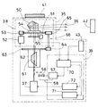
図1は回転レーザ装置35の主要部を示しており、該回転レーザ装置35は複数のレーザ光線36を射出するレーザ発光部37、前記レーザ光線36を基準平面内に回転照射する回動部38、該回動部38の回転、前記レーザ発光部37の発光状態等を制御する制御部39を具備している。前記回転レーザ装置35の上面には視準器41を具備し、該視準器41により受光装置42に対して前記回転レーザ装置35の向きを概略設定することができる。又、該回転レーザ装置35は受光部43を具備し、前記受光装置42からの反射レーザ光線を受光する様になっている。
【0021】
前記レーザ発光部37は所要数(図示では4個)のレーザダイオード44a,44b,44c,44dを直線上に配列した発光体45、コリメートレンズ46を有し、前記発光体45から射出された前記各レーザ光線36を平行光束として、又光軸に対して所定の角度を持って射出する。
【0022】
前記コリメートレンズ46の光軸上には前記回動部38が前記コリメートレンズ46の光軸を中心に回転する様に回転自在に設けられる。前記回動部38には走査ギア51が設けられ、該走査ギア51は前記回転レーザ装置35のフレーム(図示せず)に固着された走査モータ52の駆動ギア53に噛合する。該駆動ギア53の駆動により、前記走査ギア51を介して前記回動部38が回転する。
【0023】
前記走査ギア51は回転自在に支持された回転筒54に固着され、該回転筒54の上面にはペンタプリズム50が取付けられ、前記回転筒54の所要位置には前記レーザ光線36の照射方向を検出するエンコーダ55が設けられている。
【0024】
前記レーザ発光部37と前記回動部38との間、前記コリメートレンズ46の光軸上の凹レンズ56が光軸に対して直行する方向から出入り可能に設けられ、該凹レンズ56は傾斜角変更駆動部57によって前記コリメートレンズ46の光軸上に出入れされる様になっている。而して、前記凹レンズ56、傾斜角変更駆動部57はレーザ光線射出角変更手段58を構成する。該レーザ光線射出角変更手段58によって、照射されるレーザ光線は複数のグループが形成される。例えば第1グループでは1段目のレーザ光線の傾斜角度は−15°、2段目が0°、3段目が15°、4段目が30°、5段目が45°、又第2グループについては1段目のレーザ光線の傾斜角度は−10°、2段目が0°、3段目が10°、4段目が20°、5段目が40°である。前記凹レンズ56は、凸レンズでも回折レンズでもホログラムであっても同様に、扇状の広がりを可変するものであればよい。
【0025】
前記コリメートレンズ46の光軸上で前記回動部38と前記凹レンズ56との間には、イメージローテイタープリズム61が配設されている。該イメージローテイタープリズム61は1回転で像を2回転させる作用があり、後述する様に、該イメージローテイタープリズム61は前記回動部38に対して1:2の回転比となる様に連結されている。
【0026】
前記イメージローテイタープリズム61は回転自在に支持されたプリズムホルダ62により保持され、該プリズムホルダ62には同調ギア63が設けられ、該同調ギア63にアイドルギア64が噛合している。前記走査ギア51にアイドルギア65が噛合され、該アイドルギア65と前記アイドルギア64とが同軸に固着され、前記走査ギア51、アイドルギア65、アイドルギア64、同調ギア63により、前記走査ギア51と前記同調ギア63との回転比が2:1の減速比となるギア列66が形成される。
【0027】
而して、前記回動部38が2回転すると前記イメージローテイタープリズム61が1回転する。
【0028】
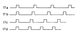
前記制御部39は主に演算器70、走査モータ駆動部71、発光体駆動部72、前記傾斜角変更駆動部57から構成され、前記演算器70は前記走査モータ駆動部71を制御して前記走査モータ52を駆動し、又前記発光体駆動部37を制御し、更に前記傾斜角変更駆動部57を制御する。前記発光体駆動部72は前記レーザダイオード44a,44b,44c,44dを図3に示される様な所定の周波数に変調し、更に該レーザダイオード44a,44b,44c,44dをそれぞれ所定のタイミングで点滅させることが可能である。
【0029】
前記発光体45の前記レーザダイオード44a,44b,44c,44dより射出されたレーザ光線36a,36b,36c,36dは鉛直面内にある。前述した様に前記走査ギア51と同調ギア63とは前記ギア列66により回転比が2:1で同期回転し、前述した様に該イメージローテイタープリズム61は1回転で像を2回転させることから前記ペンタプリズム50に入射する光軸は前記ペンタプリズム50の回転に同期して1:1の割合で回転する。而して、前記ペンタプリズム50の回転位置に拘らず、該ペンタプリズム50より照射される前記レーザ光線36a,36b,36c,36dは鉛直面内に位置した状態で照射される。
【0030】
而して、前記発光体45により前記レーザ光線36を発光させ、前記走査モータ駆動部71を介して前記走査モータ52を駆動すると、複数の前記レーザ光線36a,36b,36c,36dにより図4に示される様に水平基準面の外に円錐基準面が複数形成される。従って、各円錐基準面からは傾斜した基準線が得られる。而して、前記レーザ光線36b,36c,36dが光軸に対する角度を所望の値に設定しておけば、水平に対して所望角度の傾斜基準線が得られる。該傾斜基準線により傾斜角の設定を行え、更に傾斜方向での距離設定、位置決めが行える。又、前記レーザ光線36b,36c,36dで同時に複数の基準面を形成すれば、複数箇所で同時に異なった基準面での作業が可能となる。
【0031】
該レーザ光線36b,36c,36dの傾斜角は前記レーザ光線射出角変更手段58によって変更が可能である。即ち、前記凹レンズ56を前記コリメートレンズ46の光軸上に挿入することで、前記レーザ光線36b,36c,36dの光軸に対する角度が広がり、前記ペンタプリズム50より射出される前記レーザ光線36b,36c,36dの水平に対する傾斜角も増大する。
【0032】
特に、図示していないが複数の凹レンズを前記コリメートレンズ46の光軸に対し個別に出し入れ可能とすることで、複数段階の傾斜角調整が可能となる。
【0033】
更に、前記発光体駆動部72は前記レーザダイオード44a,44b,44c,44dを個々に周波数変調をして発光駆動しているので、受光側で変調周波数を検出する様にすれば、複数同時にレーザ光線が照射されたとしても、誤認を生ずることはない。或は、該レーザダイオード44a,44b,44c,44dは個々に点滅することができるので、必要な傾斜をもつレーザ光線のみを照射する様、該レーザダイオード44a,44b,44c,44dを点灯してもよい。
【0034】
図5、図6に於いて、前記受光装置42を説明する。
【0035】
受光装置42の受光面には受光した光信号を光電変換する縦長短冊状の受光部74が設けられ、該受光部74と平行に表示部79が設けられている。該表示部79にはレーザ光線のグループ毎の各レーザ光線の傾斜角を示す傾斜角グループ表示85とレーザ光線の照射位置の修正方向を示す矢印表示86とが設けられている、更に作業情報を表示する為の文字表示(図示せず)が設けられている。又、前記受光部74、表示部79の下側に、操作部73が設けられ、該操作部73はON−0FFスイッチ87、切替えスイッチ88等の操作スイッチを有する。更に、前記受光装置42はブザー89、罫描き用のノッチ90を有する。
【0036】
前記受光装置42は以下に述べる受光状態判断部75を有している。
【0037】
受光状態判断部75は、主に受光信号検出回路76、演算部77、表示駆動部78、記憶部80を具備する。前記受光部74からの受光信号は受光信号検出回路76に入力される。該受光信号検出回路76には増幅器、電気的フィルタ等の信号処理回路が含まれる。該受光信号検出回路76からの信号は演算部77に入力される。
【0038】
前記記憶部80には受光するレーザ光線の識別データ、識別したレーザ光線の傾斜角度データ及び識別データに基づき所要の情報を演算する演算プログラムが記憶されている。前記レーザ光線の識別データとしては、同時に照射される複数のレーザ光線が属するグループ、レーザ光線の変調態様とレーザ光線との関連付け、或は後述する様にレーザ光線の分割の態様とレーザ光線との関連付等であり、傾斜角度データとしてはグループ別のレーザ光線それぞれの傾斜角度、例えば第1グループについては、1段目のレーザ光線の傾斜角度が−15°、2段目が0°、3段目が15°、4段目が30°、5段目が45°、又第2グループについては1段目のレーザ光線の傾斜角度が−10°、2段目が0°、3段目が10°、4段目が20°、5段目が40°である等のデータである。
【0039】
前記演算プログラムは、例えば前記受光部74が同時に少なくとも2つのレーザ光線を受光する場合に、識別された受光レーザ光線、2つのレーザ光線の受光位置の距離、それぞれのレーザ光線の傾斜角データに基づき受光装置42と回転レーザ装置迄の距離を演算する為のものである。
【0040】
前記演算部77は前記レーザ光線の識別データより受光しているレーザ光線が、前記レーザ光線36b,36c,36dの内どの光線であるかを特定する。又、前記演算部77は前記レーザ光線の識別データ、傾斜角度データと前記演算プログラムにより、前記受光装置42と回転レーザ装置35迄の距離を演算する。演算結果は前記表示駆動部78を制御し、前記表示部79に演算結果を表示する。演算結果の表示は、測定距離の表示に限らず、検出しているレーザ光線はどのグループに属し、そのグループの何段目のものか、傾斜角度はいくらか(前記傾斜角グループ表示85)、更に、受光部74に対する照射位置の修正表示(前記矢印表示86)等である。
【0041】
前記操作部73からは前記回転レーザ装置35が設定したレーザ光線のグループを選択する。グループを選択することにより、グループ毎のデータが前記表示部79に択一的に表示され、又前記演算部77は選択されたグループの識別データを演算に使用する。図5では第1グループを選択し、更に受光するレーザ光線は3段目の傾斜角が15°のものを選択していることを示している。言う迄もないが、0°を選択すれば水平基準面を選択したこととなる。又、第2グループを選択すれば、傾斜角グループ表示85の表示は−10°、0°、10°、20°、40°と変更される。
【0042】
作業者は、前記表示部79の表示を見てレーザ光線の基準面が正しく選択されているか、作業が正しく行われているかを認識することができる。
【0043】
前記受光装置42からのレーザ光線36b,36c,36dの反射光は、前記受光部43が受光することができるが、該受光部43に図6で示した前記受光状態判断部75を設ければ、前記回転レーザ装置35に於いても受光している反射レーザ光線が前記レーザ光線36b,36c,36dのいずれであるかを識別することができる。識別することで、レーザ光線の選択がされ、その方向のみのレーザ照射が可能となる。
【0044】
図7はレーザ発光部37の変更例を示しており、前記発光体45に前記レーザダイオード44a,44b,44c,44dを設けるスペースがない場合、該レーザダイオード44a,44b,44c,44dを別の場所に設け、光ファイバ81a,81b,81c,81dにより導き、直線上の発光体を形成してもよい
。
【0045】
又、上述した様に複数の前記レーザ光線36を判別できる様に個々の該レーザ光線36について周波数が異なる様に変調させたが、周波数の周期と該レーザ光線36の走査速度との関係でパルス間隔が前記受光装置42の受光部74をレーザ光線36が通過する時間より長い場合は、前記受光装置42が前記レーザ光線36を検知しない場合も生じる。この様な場合は、図8に示す様に、前記ペンタプリズム50の下面にシリンダレンズ82を設け、各レーザ光線36a,36b,36c,36dを回転方向に拡散させ、扇状のレーザ光線を射出する様にしてもよい。レーザ光線が回転方向に広がることでパルス間隔が前記受光装置42の通過時間より長い場合でも、該受光装置42のレーザ光線非検知状態をなくすことができる。
【0046】
更に又、上記実施の形態では前記レーザ光線36a,36b,36c,36d毎に周波数を変えて変調させたが、レーザ光線を変調する代りに、前記各レーザ光線36を回転方向に複数分割し、各レーザ光線36a,36b,36c,36d毎に分割のパターンを変えてもよい。
【0047】
斯かる分割したレーザ光線で回転走査すると、前記受光部74から発せられる受光信号は各レーザ光線特有のものとなり、前記受光状態判断部75はレーザ光線36a,36b,36c,36dそれぞれを信号パターンにより特定することが可能となる。
【0048】
図9は回折パターン83を前記ペンタプリズム50のレーザ光線透過面に設け、前記各レーザ光線36a,36b,36c,36dを回転方向に3分割し、更に該各レーザ光線36a,36b,36c,36d毎に分割の態様が異なってくる様に回折パターンの内容を異ならせたものである。尚、前記回折パターン83は透過面だけでなく、反射面にも設けることができる。
【0049】
前記レーザ光線36a,36b,36c,36dの分割の態様の一例を図10(A)に示し、前記レーザ光線36は3分割し、分割した最初の分割レーザ光線と中間の分割レーザ光線との間隔は前記レーザ光線36a,36b,36c,36d全て同一とし、中間の分割レーザ光線と最後の分割レーザ光線との間隔は漸次拡大する様にしたものである。従って、受光信号は図10(B)に示す様に、最初のパルスと2番目のパルスとの間隔が該レーザ光線36a,36b,36c,36dの全てについて同一となり、2番目のパルスと3番目のパルスとの間隔は漸次長くする。従って、パルスの発生パターンを識別することで該レーザ光線36a,36b,36c,36dの内いずれかであるかを特定できる。
【0050】
又、前記制御部39は前記回動部38の回転位置を前記エンコーダ55の出力に基づいて検知し、検知結果に基づき前記受光装置42の範囲を往復走査させてもよいし、前記レーザ発光部37を制御し前記受光装置42の範囲のみをレーザ光線の発光を限定して回転させてもよい。
【0051】
上記説明では受光部74で1つの基準面を検出する場合を説明したが、2つの基準面を同時に検出する場合も勿論可能であり、この場合は回転レーザ装置35と受光装置42との間の距離の測定が可能である。
【0052】
前記演算部77が前記記憶部80に記憶されている各基準面についての識別データを呼込み、それぞれの基準面について何段目かの特定を行うと共に各基準面についての傾斜角度を特定する。又前記受光部74での受光位置上での2つの基準面の距離を演算する。而して、前記傾斜角度、受光距離を基に前記演算プログラムにより受光装置と回転レーザ装置との間の距離を演算する。演算結果は前記表示部79に表示する。尚、距離表示についての表示器については図示していない。
【0053】
而して、測距装置等高価な装置を設けることなく、簡便な方法で直ちに距離測定が行える。
【0054】
【発明の効果】
以上述べた如く本発明によれば、レーザ光線1回転中での複数の範囲でのレベル設定が可能であり、1台の回転レーザ装置により複数位置での土木、建設作業が可能となる。又、レーザ光線により複数の傾斜基準線が同時に而も簡単に形成し得、傾斜基準線を形成する為の機構は著しく簡単である。又、受光装置は複数のレーザ光線が同時に照射された場合もレーザ光線の識別が可能であるので、誤作業を招くことはなく、更に安価な機構で距離測定が行えるという優れた効果を発揮する。
【図面の簡単な説明】
【図1】本発明の回転レーザ装置の実施の形態の要部を示すブロック図である。
【図2】該実施の形態に用いられる発光部の説明図である。
【図3】該発光部から発せられるレーザ光線の変調状態を示す説明図である。
【図4】該実施の形態に於ける基準面形成状態を示す説明図である。
【図5】本発明の受光装置の実施の形態の正面図である。
【図6】該受光装置に設けられる受光状態判断部のブロック図である。
【図7】本発明の実施の形態の応用例であり、発光部の他の例を示す説明図である。
【図8】本発明の実施の形態の応用例であり、射出するレーザ光線を拡散する場合の説明図である。
【図9】本発明の実施の形態の応用例であり、射出するレーザ光線を回転方向に分割する場合の説明図である。
【図10】(A)(B)は該応用例に於けるレーザ光線の分割態様、及び受光信号の態様を示す説明図である。
【図11】従来の回転レーザ装置を示す断面図である。
【符号の説明】
35 回転レーザ装置
36 レーザ光線
37 レーザ発光部
38 回動部
39 制御部
42 受光装置
44 レーザダイオード
45 発光体
56 凹レンズ
57 傾斜角変更駆動部
61 イメージローテイタープリズム
66 ギア列
70 演算器
73 操作部
74 受光部
76 受光信号検出回路
79 表示部
80 記憶部[0001]
BACKGROUND OF THE INVENTION
The present invention forms a reference point, a reference line, and a measurement reference plane by irradiating a laser beam, or reciprocatingly scanning and further rotating, particularly with respect to a horizontal reference plane in addition to a horizontal reference plane. The present invention relates to a rotary laser device capable of simultaneously forming an inclination setting surface inclined at a predetermined angle, and a light receiving device used in the rotary laser device.
[0002]
[Prior art]
In order to create a horizontal reference level over a wide range, a rotating laser device is used instead of an optical level device.
[0003]
In recent years, rotating laser devices have been used in the measurement in the height direction, particularly in the case of forming lines, planes, and the like based on a reference height. The rotating laser device rotates while irradiating a laser beam in the horizontal direction, or reciprocates or stops, forms a rotating reference plane, or a partial reference line, reference plane, and further a reference line, It forms a reference point.
[0004]
For example, it is used to form a reference horizontal line for positioning the window frame in relation to the interior, and for civil engineering work, it is used to form a reference horizontal plane for embedding and forming a cut surface. . Further, the rotating laser device is also used for setting a reference point in setting the inclination of a staircase or the like, and there is one that can form a reference plane inclined in one direction or two directions.
[0005]
Japanese Patent Laid-Open No. 6-26861 discloses a conventional rotary laser device capable of forming an inclined reference plane. FIG. Is outlined below.
[0006]
A truncated
[0007]
Two sets of tilting mechanisms 10 (one not shown) are provided around the
[0008]
A
[0009]
The
[0010]
The
[0011]
The inclination angle is set by the
[0012]
Next, the
[0013]
[Problems to be solved by the invention]
In the conventional rotary laser device described above, in order to form the tilt reference plane, the
[0014]
In view of such a situation, the present invention provides a rotary laser device capable of simultaneously forming a plurality of reference surfaces without tilting the laser projector, and each reference surface is formed when the plurality of reference surfaces are formed simultaneously. It is an object of the present invention to provide a light-receiving device that can be identified and that does not cause erroneous work.
[0015]
[Means for Solving the Problems]
The present invention relates to a rotary laser device that emits a plurality of laser beams separately in the vertical direction and rotationally irradiates the plurality of laser beams to form a plurality of laser beam reference planes. The laser emits a plurality of laser beams. A light emitting unit, a rotating unit that rotates and irradiates a laser beam from the laser emitting unit to form a laser reference plane, and is provided between the rotating unit and the laser emitting unit. The present invention relates to a rotary laser device comprising an image rotator prism that rotates synchronously with a rotation ratio of / 2, and a rotary laser provided with laser beam emission angle changing means for changing the emission angle of a laser beam emitted from the laser emission unit The present invention relates to an apparatus, and also relates to a rotating laser apparatus in which the laser beam emission angle changing means includes an optical member inserted into and removed from an optical path of a laser beam emitted from the laser emission unit. A plurality of laser beams emitted from a plurality of independently driven light emitting elements, the light emitting elements being respectively modulated or flashing differently, and the plurality of laser beams are respectively The present invention relates to a rotating laser device that is diffused in a rotating direction, and the laser beam is divided into a plurality of parts in the rotating direction, and the laser beam is divided according to a diffraction pattern. The present invention relates to a rotary laser device to be divided.
[0016]
In addition, a light receiving unit capable of receiving a plurality of laser beams emitted from the rotary laser device, a light receiving state determining unit that calculates a light receiving state based on a light receiving signal from the light receiving unit, and a calculation result of the light receiving state determining unit In addition, the light receiving state determination unit stores identification data such as the type of laser beam and the inclination angle of the laser beam for each type. The laser beam is based on the identification data. In addition, the light receiving state determination unit calculates a laser light receiving position and a distance to the rotating laser device based on the identification data when a plurality of laser beams are received. Further, the display unit is capable of group display of the identification data for a plurality of laser beams irradiated at once from the rotary laser device. Those of the light-receiving device selection display group are possible.
[0017]
Since a plurality of reference surfaces are formed at the same time, simultaneous work can be performed at the construction position, and a desired tilt reference line can be obtained immediately without the tilt setting operation of the reference surface.
[0018]
The light receiving device individually identifies a plurality of laser beams irradiated simultaneously from the rotating laser device, and further calculates a distance between the light receiving device and the rotating laser device. The identification result and the calculation result are displayed on the display unit.
[0019]
DETAILED DESCRIPTION OF THE INVENTION
Hereinafter, embodiments of the present invention will be described with reference to the drawings.
[0020]
FIG. 1 shows a main part of a
[0021]
The laser
[0022]
On the optical axis of the collimating
[0023]
The
[0024]
A
[0025]
An
[0026]
The
[0027]
Thus, when the rotating
[0028]
The
[0029]
[0030]
Thus, when the
[0031]
The tilt angles of the
[0032]
In particular, although not shown, a plurality of concave lenses can be individually taken in and out with respect to the optical axis of the collimating
[0033]
Further, since the light
[0034]
The
[0035]
The light receiving surface of the
[0036]
The
[0037]
The light reception
[0038]
The
[0039]
For example, when the
[0040]
The
[0041]
From the
[0042]
The operator can recognize whether the reference plane of the laser beam is correctly selected or whether the operation is correctly performed by looking at the display on the
[0043]
Reflected light of the
[0044]
FIG. 7 shows a modified example of the laser
.
[0045]
Further, as described above, each of the
[0046]
Furthermore, in the above embodiment, each
[0047]
When rotationally scanning with such a divided laser beam, the received light signal emitted from the
[0048]
In FIG. 9, a
[0049]
FIG. 10A shows an example of how the
[0050]
The
[0051]
In the above description, the case where one reference plane is detected by the
[0052]
The
[0053]
Thus, the distance can be measured immediately by a simple method without providing an expensive device such as a distance measuring device.
[0054]
【The invention's effect】
As described above, according to the present invention, levels can be set in a plurality of ranges during one rotation of the laser beam, and civil engineering and construction work can be performed at a plurality of positions by one rotating laser device. Also, a plurality of inclined reference lines can be easily formed simultaneously by the laser beam, and the mechanism for forming the inclined reference lines is extremely simple. In addition, since the light receiving device can identify laser beams even when a plurality of laser beams are irradiated at the same time, there is no erroneous work, and an excellent effect that distance measurement can be performed with an inexpensive mechanism is exhibited. .
[Brief description of the drawings]
FIG. 1 is a block diagram showing a main part of an embodiment of a rotary laser device of the present invention.
FIG. 2 is an explanatory diagram of a light emitting unit used in the embodiment.
FIG. 3 is an explanatory diagram showing a modulation state of a laser beam emitted from the light emitting unit.
FIG. 4 is an explanatory diagram showing a reference surface forming state in the embodiment.
FIG. 5 is a front view of an embodiment of a light receiving device of the present invention.
FIG. 6 is a block diagram of a light receiving state determination unit provided in the light receiving device.
FIG. 7 is an explanatory diagram showing another example of a light emitting unit, which is an application example of the embodiment of the present invention.
FIG. 8 is an application diagram of the embodiment of the present invention, and is an explanatory diagram in the case of diffusing an emitted laser beam.
FIG. 9 is an application example of the embodiment of the present invention, and is an explanatory diagram in a case where an emitted laser beam is divided in a rotation direction.
FIGS. 10A and 10B are explanatory diagrams showing a laser beam splitting mode and a received light signal mode in the application example. FIGS.
FIG. 11 is a cross-sectional view showing a conventional rotary laser device.
[Explanation of symbols]
35 Rotating laser device
36 Laser beam
37 Laser emitter
38 Rotating part
39 Control unit
42 Photodetector
44 Laser diode
45 illuminant
56 concave lens
57 Inclination angle change drive unit
61 Image Rotator Prism
66 Gear train
70 Calculator
73 Operation unit
74 Receiver
76 Light reception signal detection circuit
79 Display
80 storage
Claims (11)
Priority Applications (4)
| Application Number | Priority Date | Filing Date | Title |
|---|---|---|---|
| JP34410098A JP4159153B2 (en) | 1998-12-03 | 1998-12-03 | Rotating laser device and light receiving device |
| US09/447,697 US6314651B1 (en) | 1998-12-03 | 1999-11-23 | Rotary laser irradiating system and photodetection system |
| EP99309676A EP1006339B1 (en) | 1998-12-03 | 1999-12-02 | Rotary laser irradiating system and photodetection system |
| DE69928203T DE69928203T2 (en) | 1998-12-03 | 1999-12-02 | Rotating laser illumination system and photodetector system |
Applications Claiming Priority (1)
| Application Number | Priority Date | Filing Date | Title |
|---|---|---|---|
| JP34410098A JP4159153B2 (en) | 1998-12-03 | 1998-12-03 | Rotating laser device and light receiving device |
Publications (3)
| Publication Number | Publication Date |
|---|---|
| JP2000171252A JP2000171252A (en) | 2000-06-23 |
| JP2000171252A5 JP2000171252A5 (en) | 2006-03-23 |
| JP4159153B2 true JP4159153B2 (en) | 2008-10-01 |
Family
ID=18366653
Family Applications (1)
| Application Number | Title | Priority Date | Filing Date |
|---|---|---|---|
| JP34410098A Expired - Fee Related JP4159153B2 (en) | 1998-12-03 | 1998-12-03 | Rotating laser device and light receiving device |
Country Status (4)
| Country | Link |
|---|---|
| US (1) | US6314651B1 (en) |
| EP (1) | EP1006339B1 (en) |
| JP (1) | JP4159153B2 (en) |
| DE (1) | DE69928203T2 (en) |
Families Citing this family (29)
| Publication number | Priority date | Publication date | Assignee | Title |
|---|---|---|---|---|
| JP4614565B2 (en) * | 2001-03-28 | 2011-01-19 | 株式会社トプコン | Laser beam irradiation device |
| JP4870283B2 (en) * | 2001-07-13 | 2012-02-08 | 株式会社トプコン | Laser sighting device |
| US7252874B2 (en) | 2001-09-04 | 2007-08-07 | Tohoku Ricoh Company, Ltd. | Heat-sensitive stencil, method of preparing stencil printing master and stencil printer |
| JP3840119B2 (en) * | 2002-02-08 | 2006-11-01 | 株式会社ソキア | Laser centripetal device |
| US6892464B2 (en) * | 2002-03-13 | 2005-05-17 | Kabushiki Kaisha Topcon | Laser sighting device |
| JP3809136B2 (en) * | 2002-08-21 | 2006-08-16 | ペンタックス株式会社 | Station indication device |
| US6763598B1 (en) * | 2003-05-06 | 2004-07-20 | Sean & Stephen Corp. | Laser level with lens switching mechanism |
| DE102004053249B4 (en) * | 2004-11-04 | 2006-08-17 | Hilti Ag | Construction laser with tilting deflection |
| TWI261107B (en) * | 2005-02-03 | 2006-09-01 | Asia Optical Co Inc | Laser tilt apparatus and the method thereof |
| US7497019B2 (en) * | 2005-08-04 | 2009-03-03 | Irwin Industrial Tool Company | Laser reference device |
| US7392592B2 (en) | 2005-10-07 | 2008-07-01 | Milwaukee Electric Tool Corporation | Ruggedized laser level |
| JP5226963B2 (en) * | 2007-03-06 | 2013-07-03 | 株式会社トプコン | Laser measurement system |
| JP5207665B2 (en) * | 2007-06-08 | 2013-06-12 | 株式会社トプコン | Measuring system |
| DE102008041033A1 (en) | 2008-08-06 | 2010-02-11 | Hilti Aktiengesellschaft | A rotary construction |
| US8094355B2 (en) * | 2009-04-29 | 2012-01-10 | Corning Incorporated | Laser projection system with a spinning polygon for speckle mitigation |
| JP5550855B2 (en) * | 2009-06-12 | 2014-07-16 | 株式会社トプコン | Rotating laser emission device |
| EP2453204A1 (en) | 2010-11-10 | 2012-05-16 | Leica Geosystems AG | Construction laser system and method |
| US9127935B2 (en) * | 2012-01-04 | 2015-09-08 | Chris Olexa | Laser centering tool for surface areas |
| US9866322B2 (en) | 2012-03-15 | 2018-01-09 | Leica Geosystems Ag | Laser receiver |
| EP2639549A1 (en) | 2012-03-15 | 2013-09-18 | Leica Geosystems AG | Laser receiver |
| DE102012102651B3 (en) * | 2012-03-27 | 2013-07-18 | Jenoptik Robot Gmbh | Test device and test method for a traffic monitoring device with a laser scanner |
| US8937725B2 (en) * | 2012-06-14 | 2015-01-20 | Nikon Corporation | Measurement assembly including a metrology system and a pointer that directs the metrology system |
| EP3376161B1 (en) * | 2013-12-05 | 2021-07-07 | Trimble AB | Operating a total station with a stair-like scanning profile |
| WO2015082217A2 (en) | 2013-12-05 | 2015-06-11 | Trimble Ab | Distance measurement instrument with scanning function |
| JP2015143620A (en) * | 2014-01-31 | 2015-08-06 | 株式会社デンソーウェーブ | laser radar device |
| WO2018068248A1 (en) | 2016-10-13 | 2018-04-19 | Stanley Black & Decker, Inc. | Power tool |
| WO2019174436A1 (en) * | 2018-03-12 | 2019-09-19 | Oppo广东移动通信有限公司 | Control method, control device, depth camera and electronic device |
| US11320263B2 (en) * | 2019-01-25 | 2022-05-03 | Stanley Black & Decker Inc. | Laser level system |
| KR20230040088A (en) * | 2021-09-15 | 2023-03-22 | 현대자동차주식회사 | Lighting device for implementing image |
Family Cites Families (18)
| Publication number | Priority date | Publication date | Assignee | Title |
|---|---|---|---|---|
| JPS60242313A (en) * | 1984-05-16 | 1985-12-02 | Kubota Ltd | Beam light scanning device |
| JP3226970B2 (en) | 1992-07-09 | 2001-11-12 | 株式会社トプコン | Laser surveying machine |
| US5823679A (en) * | 1993-09-17 | 1998-10-20 | Omega Engineering, Inc. | Method and apparatus for measuring temperature including aiming light |
| IL108059A (en) * | 1993-12-17 | 1998-02-22 | Laser Ind Ltd | Method and apparatus for applying laser beams to a working surface, particularly for ablating tissue |
| US5626424A (en) * | 1994-07-21 | 1997-05-06 | Raytek Subsidiary, Inc. | Dual light source aiming mechanism and improved actuation system for hand-held temperature measuring unit |
| US5533268A (en) * | 1994-08-08 | 1996-07-09 | Miles D. Willetts | Laser deflection apparatus for laser compass |
| EP0722080B1 (en) * | 1995-01-11 | 2000-03-15 | Kabushiki Kaisha Topcon | Laser levelling device |
| JP3277776B2 (en) * | 1995-11-20 | 2002-04-22 | ミノルタ株式会社 | Radiation thermometer aiming device |
| CH691931A5 (en) * | 1995-12-21 | 2001-11-30 | Ammann Holding Ag | Laser leveling device and method for operating a laser leveling instrument and associated auxiliaries. |
| US5838431A (en) * | 1996-01-16 | 1998-11-17 | Asahi Kogaku Kogyo Kabushiki Kaisha | Laser marking device |
| JPH09210687A (en) * | 1996-01-31 | 1997-08-12 | Topcon Corp | Laser level |
| US5748321A (en) * | 1996-05-07 | 1998-05-05 | The United States Of America As Represented By The Department Of Energy | Position and orientation tracking system |
| JPH10213435A (en) * | 1997-01-29 | 1998-08-11 | Nikon Corp | Reference-light generating device |
| US5953108A (en) * | 1997-05-28 | 1999-09-14 | Laser Alignment, Inc. | Laser beam projector power and communication system |
| DE19733919C2 (en) * | 1997-08-05 | 1999-08-26 | Busch Dieter & Co Prueftech | Device and method for aligning bodies |
| JP4152504B2 (en) * | 1997-11-19 | 2008-09-17 | 株式会社トプコン | Reference irradiation light detector |
| US6163969A (en) * | 1998-08-04 | 2000-12-26 | Quarton Inc. | 3D laser leveler |
| US6202312B1 (en) * | 1999-03-08 | 2001-03-20 | Levelite Technology, Inc. | Laser tool for generating perpendicular lines of light on floor |
-
1998
- 1998-12-03 JP JP34410098A patent/JP4159153B2/en not_active Expired - Fee Related
-
1999
- 1999-11-23 US US09/447,697 patent/US6314651B1/en not_active Expired - Lifetime
- 1999-12-02 EP EP99309676A patent/EP1006339B1/en not_active Expired - Lifetime
- 1999-12-02 DE DE69928203T patent/DE69928203T2/en not_active Expired - Lifetime
Also Published As
| Publication number | Publication date |
|---|---|
| DE69928203D1 (en) | 2005-12-15 |
| JP2000171252A (en) | 2000-06-23 |
| US6314651B1 (en) | 2001-11-13 |
| EP1006339A2 (en) | 2000-06-07 |
| DE69928203T2 (en) | 2006-11-30 |
| EP1006339A3 (en) | 2001-08-08 |
| EP1006339B1 (en) | 2005-11-09 |
Similar Documents
| Publication | Publication Date | Title |
|---|---|---|
| JP4159153B2 (en) | Rotating laser device and light receiving device | |
| JP4180718B2 (en) | Rotating laser device | |
| JP4216386B2 (en) | Rotating laser device | |
| US7022962B2 (en) | Position determining apparatus | |
| US5907907A (en) | Laser leveling system | |
| EP0806630B1 (en) | Rotary laser system | |
| JP4712212B2 (en) | Laser sighting device | |
| JP4796834B2 (en) | Distance measuring method and distance measuring device | |
| EP1914565A9 (en) | Distance measuring device | |
| US20020057426A1 (en) | Position determination and adjustment system and light sensing device used for the same | |
| US6246502B1 (en) | Optical scanning apparatus | |
| EP0422946A1 (en) | Digitising the surface of an irregularly shaped article, e.g. a shoe last | |
| EP2053354A1 (en) | Laser surveying system | |
| JP4282432B2 (en) | Light receiving device for rotary laser device | |
| JP2008089393A (en) | Optical device and optical measurement system | |
| US6121598A (en) | Laser transmitter incorporating target dither | |
| US6151106A (en) | Laser irradiation system | |
| US6108075A (en) | Laser beam emitting apparatus | |
| EP4160145A1 (en) | Surveying instrument | |
| JP2019015602A (en) | Survey system | |
| JP3568841B2 (en) | Displacement measuring device and method | |
| JP2513226B2 (en) | Positioning device and processing device using the same | |
| JPH0611341A (en) | Optical apparatus for measuring distance | |
| JPH07190771A (en) | Survey method and surveying device for this method | |
| JP2000162525A (en) | Optical scanner |
Legal Events
| Date | Code | Title | Description |
|---|---|---|---|
| A521 | Written amendment |
Free format text: JAPANESE INTERMEDIATE CODE: A523 Effective date: 20051130 |
|
| A621 | Written request for application examination |
Free format text: JAPANESE INTERMEDIATE CODE: A621 Effective date: 20051130 |
|
| A131 | Notification of reasons for refusal |
Free format text: JAPANESE INTERMEDIATE CODE: A131 Effective date: 20080122 |
|
| A521 | Written amendment |
Free format text: JAPANESE INTERMEDIATE CODE: A523 Effective date: 20080324 |
|
| A131 | Notification of reasons for refusal |
Free format text: JAPANESE INTERMEDIATE CODE: A131 Effective date: 20080422 |
|
| A521 | Written amendment |
Free format text: JAPANESE INTERMEDIATE CODE: A523 Effective date: 20080612 |
|
| TRDD | Decision of grant or rejection written | ||
| A01 | Written decision to grant a patent or to grant a registration (utility model) |
Free format text: JAPANESE INTERMEDIATE CODE: A01 Effective date: 20080708 |
|
| A01 | Written decision to grant a patent or to grant a registration (utility model) |
Free format text: JAPANESE INTERMEDIATE CODE: A01 |
|
| A61 | First payment of annual fees (during grant procedure) |
Free format text: JAPANESE INTERMEDIATE CODE: A61 Effective date: 20080715 |
|
| R150 | Certificate of patent or registration of utility model |
Free format text: JAPANESE INTERMEDIATE CODE: R150 |
|
| FPAY | Renewal fee payment (event date is renewal date of database) |
Free format text: PAYMENT UNTIL: 20110725 Year of fee payment: 3 |
|
| FPAY | Renewal fee payment (event date is renewal date of database) |
Free format text: PAYMENT UNTIL: 20110725 Year of fee payment: 3 |
|
| FPAY | Renewal fee payment (event date is renewal date of database) |
Free format text: PAYMENT UNTIL: 20120725 Year of fee payment: 4 |
|
| FPAY | Renewal fee payment (event date is renewal date of database) |
Free format text: PAYMENT UNTIL: 20120725 Year of fee payment: 4 |
|
| FPAY | Renewal fee payment (event date is renewal date of database) |
Free format text: PAYMENT UNTIL: 20130725 Year of fee payment: 5 |
|
| R250 | Receipt of annual fees |
Free format text: JAPANESE INTERMEDIATE CODE: R250 |
|
| R250 | Receipt of annual fees |
Free format text: JAPANESE INTERMEDIATE CODE: R250 |
|
| R250 | Receipt of annual fees |
Free format text: JAPANESE INTERMEDIATE CODE: R250 |
|
| R250 | Receipt of annual fees |
Free format text: JAPANESE INTERMEDIATE CODE: R250 |
|
| LAPS | Cancellation because of no payment of annual fees |