EP1248120A2 - Dual-Mode Suchkopf - Google Patents
Dual-Mode Suchkopf Download PDFInfo
- Publication number
- EP1248120A2 EP1248120A2 EP02007006A EP02007006A EP1248120A2 EP 1248120 A2 EP1248120 A2 EP 1248120A2 EP 02007006 A EP02007006 A EP 02007006A EP 02007006 A EP02007006 A EP 02007006A EP 1248120 A2 EP1248120 A2 EP 1248120A2
- Authority
- EP
- European Patent Office
- Prior art keywords
- laser
- dual
- sensor
- mode
- light
- Prior art date
- Legal status (The legal status is an assumption and is not a legal conclusion. Google has not performed a legal analysis and makes no representation as to the accuracy of the status listed.)
- Granted
Links
Images

Classifications
-
- G—PHYSICS
- G01—MEASURING; TESTING
- G01S—RADIO DIRECTION-FINDING; RADIO NAVIGATION; DETERMINING DISTANCE OR VELOCITY BY USE OF RADIO WAVES; LOCATING OR PRESENCE-DETECTING BY USE OF THE REFLECTION OR RERADIATION OF RADIO WAVES; ANALOGOUS ARRANGEMENTS USING OTHER WAVES
- G01S17/00—Systems using the reflection or reradiation of electromagnetic waves other than radio waves, e.g. lidar systems
- G01S17/88—Lidar systems specially adapted for specific applications
- G01S17/89—Lidar systems specially adapted for specific applications for mapping or imaging
-
- F—MECHANICAL ENGINEERING; LIGHTING; HEATING; WEAPONS; BLASTING
- F41—WEAPONS
- F41G—WEAPON SIGHTS; AIMING
- F41G3/00—Aiming or laying means
- F41G3/06—Aiming or laying means with rangefinder
- F41G3/065—Structural association of sighting-devices with laser telemeters
-
- F—MECHANICAL ENGINEERING; LIGHTING; HEATING; WEAPONS; BLASTING
- F41—WEAPONS
- F41G—WEAPON SIGHTS; AIMING
- F41G7/00—Direction control systems for self-propelled missiles
- F41G7/008—Combinations of different guidance systems
-
- F—MECHANICAL ENGINEERING; LIGHTING; HEATING; WEAPONS; BLASTING
- F41—WEAPONS
- F41G—WEAPON SIGHTS; AIMING
- F41G7/00—Direction control systems for self-propelled missiles
- F41G7/20—Direction control systems for self-propelled missiles based on continuous observation of target position
- F41G7/22—Homing guidance systems
- F41G7/2246—Active homing systems, i.e. comprising both a transmitter and a receiver
-
- F—MECHANICAL ENGINEERING; LIGHTING; HEATING; WEAPONS; BLASTING
- F41—WEAPONS
- F41G—WEAPON SIGHTS; AIMING
- F41G7/00—Direction control systems for self-propelled missiles
- F41G7/20—Direction control systems for self-propelled missiles based on continuous observation of target position
- F41G7/22—Homing guidance systems
- F41G7/2253—Passive homing systems, i.e. comprising a receiver and do not requiring an active illumination of the target
-
- F—MECHANICAL ENGINEERING; LIGHTING; HEATING; WEAPONS; BLASTING
- F41—WEAPONS
- F41G—WEAPON SIGHTS; AIMING
- F41G7/00—Direction control systems for self-propelled missiles
- F41G7/20—Direction control systems for self-propelled missiles based on continuous observation of target position
- F41G7/22—Homing guidance systems
- F41G7/2273—Homing guidance systems characterised by the type of waves
- F41G7/2293—Homing guidance systems characterised by the type of waves using electromagnetic waves other than radio waves
Definitions
- the invention relates to an electro-optical dual-mode seeker head (passive optical and LADAR), e.g. for target-seeking missiles with imaging optical means, by which shows an object scene on an image-resolving optical sensor with a two-dimensional arrangement of passive detector elements can be mapped, one Laser, through which a laser beam is directed onto the object scene, one of which laser light reflected from an object in the object scene via the imaged optical Means acted upon sensor, and means for generating object information (e.g. Distance) from the signals of the laser sensor, the laser sensor Provides object information from different pixels of the object scene simultaneously.
- object information e.g. Distance
- the two-dimensional images are usually made passive Receive sensors, i.e. by means of sensors whose detector elements on radiation address that is emitted or reflected by the objects of the visual field.
- a passive sensor itself, unlike RADAR, for example, does not transmit any radiation out.
- Dual-mode search heads are known from DE 42 22 642 A1. They include image-processing, passive optical sensors used in homing heads for the autonomous Guiding missiles are used. The sensors of the state mentioned Technology also include a LADAR sensor. LADAR means based on Radar, "Laser Detection and Ranging”.
- Your range of tasks includes the acquisition, selection and tracking of different Targets in space, in the air, on the ground and at sea.
- the capture and selection of destinations and the determination of the stopping or meeting point is usually done based on thermal target signatures and their geometry features.
- the target signatures can be changed significantly. This is for example the case for a flying object over intensive clutter.
- a direct hit is hitting a certain point on the Target at a certain angle for the effectiveness of a missile crucial.
- Image processing based on a two-dimensional passive optical image is then only able to use the missile to a limited extent to successfully steer to the goal.
- the target acquisition, target selection and hit probability in complex scenarios are substantially improved in accordance with DE 42 22 642 A1 by the in Combination of the two-dimensional angle information with distance information, i.e. through a three-dimensional image.
- Dual mode seekers of the above State of the art obtain this distance information by using the LADAR Sensor.
- a laser beam scans the target point by point and the reflected one The beam is separated from the rest of the radiation and by means of a polarization beam splitter outgoing radiation separated and detected. From the running time of the laser pulse then the distance of the reflecting point at the target can be determined.
- a LADAR sensor has the advantage over a radar because of the shorter wavelength higher angular resolution.
- a multi-channel ladar is known from US 5,953,110 (Burns).
- the reflected laser radiation a multiple beam is turned into a multi-channel receiver detected and evaluated using simple pulse transit time measurement.
- the recipient comprises a large number of light guides, by means of which the radiation to a large number of Detectors is coupled. With this arrangement, it is possible to take three-dimensional images in Get real time.
- the arrangement should be simple and take up as little space as possible.
- the object no longer needs to be scanned successively point by point. Rather, each pixel is imaged simultaneously.
- the frame rate is then no longer limited by the sampling rate. Especially with fast movements thus the detection of the object scene is greatly improved.
- the spatial resolution of the image is no longer due to the accuracy limits with which the laser beam can be positioned.
- the laser beam only serves illuminating the object scene with coherent light and no longer needs high Accuracy to be positioned on the object. Rather, the dissolution of the third dimension delivering "laser image" determined by the grid of the laser sensor.
- the imaging optical means with which the reflected laser light on the further two-dimensional arrangement of detector elements can be mapped preferably comprise the optical means through which the object scene on the image-resolving optical sensor can be mapped.
- the laser sensor can provide information about the speed of the object be determinable. This can be done, for example, by measuring the pulse time Laser pulses in combination with a double pulse modulation, in which the laser is in one emits a defined, short distance, two pulses take place. From the measurements can then the relative speed to the object can be estimated.
- the laser sensor preferably comprises a beam guidance system with which the beam is directed the various pixels of the laser image reflect rays to a variety of Detector elements are directed.
- the beam delivery system can be of a variety be formed by light guides and each light guide at least one detector element assign. As a result, the resolution is not determined by the size of the detector elements associated electronics limited.
- the detector can be spatially separated from the Be arranged in the image plane and take on an almost arbitrary shape there.
- the light guides are preferably without further cladding to form a light guide bundle bundled. As a result, the fill factor of the light guide in the image plane and thus the Resolution increased. Between the detector-side ends of the light guide and the A two-dimensional array of detector elements can be used for a lens array Coupling of the light guide to the detector elements can be arranged.
- means for modulation of the laser beam is provided.
- the information content associated with the Laser sensor obtained will be increased. So the intensity, frequency, phase or polarization of the laser pulse can be modulated and relative to height jumps an object level further volumetric, surface and movement characteristics to be appreciated.
- the laser assembly there is a light guide for guiding the laser beam from the laser to the optical axis provided.
- the light guide enables the laser assembly to be separated to generate the laser beam from the transmission optics and allows the laser assembly to be ordered elsewhere.
- the separation of the reflected laser radiation from the rest of the radiation can preferably done via a dichroic beam splitter.
- the detectors of the Optical sensor and the laser sensor can therefore be in different positions be arranged and mutual interference is prevented.
- the Area filling factor can be further increased when the reflected laser beam is detected.
- 10 denotes an electro-optical dual-mode seeker head.
- the dual-mode seeker 10 is arranged in the nose of a missile (not shown).
- the dual-mode search head 10 comprises a passive optical sensor 12 and one active laser sensor (LADAR) 14.
- LADAR active laser sensor
- the seeker head is on a stabilized platform attached.
- the passive optical sensor 12 essentially consists of an optical system 16, a detector assembly 18, a detector-near electronics (not shown) for Control and readout of the detector and image processing electronics (not shown) with image processing software.
- the optical system 16 comprises a lens 20 for focusing the of an object emitted or reflected radiation 21 onto the detector assembly 18. Usually the infrared radiation of the object is detected, so that the lens 20 and the detector in IR range have a high effectiveness.
- the detector includes a two-dimensional cooled detector array consisting of a multitude of detector elements. With the passive optical sensor 12 two-dimensional infrared images recorded and further with an image processing electronics and software for the Target search and acquisition processed.
- the laser sensor consists of a laser module for generating the laser beam and Electronics for modulating the laser beam (not shown), an optical transmitter 22, one Receiving optics 20, optical fibers 26 (FIG. 2a) for scanning the image plane 24 of the laser sensor, a detector array 28 made up of a plurality of detector elements 30, one Coupling optics 32 which connect the light guides 26 to the corresponding detector elements 30 connects, signal processing electronics 34 and electronics for Process control of the laser sensor.
- the laser module is a conventional IR laser with the corresponding one Control electronics.
- the laser can work in pulse mode or in CW mode.
- the Laser light is fed into an optical fiber.
- the light guide is 36 in FIG. 1 designated.
- the end 38 of the light guide 36 is almost at the focal point of a lens 40.
- the laser light 37 emerging from the light guide 36 thus becomes an im essentially parallel beam 39 bundled with which the object (not shown) is illuminated.
- the transmission optics 22 with the lens 40 is located in the middle in front of the lens 20 of the optics 16 of the passive optical sensor on the optical axis before a central suppression 42 Laser beam reflected on the object is emitted by the lens 20 of the receiving optics focused.
- a dichroic mirror 44 directs the beam into the image plane 24 of the laser sensor.
- the ends 46 of the bundled light guides 26 are arranged in the image plane 24.
- the Light guides 26 are stripped and packed in a hexagonally closest packing, which results in a grid size of approximately 60 micrometers per grid point.
- a Top view of the image plane 24 is shown in Fig. 2b. Sitting in front of the light guide bundle a microlens grid with a corresponding hexagonal closest packing of the Microlenses.
- the light guides 26 become a detector array 28 with a plurality of Detector elements 30 performed.
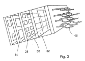
- the coupling takes place by means of a micro-optical one Grid plate 32 (lens array) trained coupling optics. This is shown in FIG. 3 again an exploded view. Behind the detector array 28 is the Evaluation electronics 34 arranged with conventional CMOS technology.
- the evaluation and three-dimensional mapping can be done in different ways:
- a pulse duration measurement in connection with a double pulse modulation provides one Estimate of the relative speed to an object.
- the laser sends double pulses at a defined, short distance two pulses out.
Landscapes
- Engineering & Computer Science (AREA)
- Physics & Mathematics (AREA)
- General Engineering & Computer Science (AREA)
- Chemical & Material Sciences (AREA)
- Combustion & Propulsion (AREA)
- Electromagnetism (AREA)
- Computer Networks & Wireless Communication (AREA)
- General Physics & Mathematics (AREA)
- Radar, Positioning & Navigation (AREA)
- Remote Sensing (AREA)
- Optics & Photonics (AREA)
- Optical Radar Systems And Details Thereof (AREA)
Abstract
Description
- Fig. 1
- ist eine schematische Darstellung der Strahlführung eines elektro-optischen Dual-Mode-Suchkopfs
- Fig.2a
- ist eine Seitenansicht der Anordnung der Lichtleitfasern in der Bildebene des Ladars und der Detektoren
- Fig.2b
- ist eine Vorderansicht der Anordnung der Lichtleitfasern in der Bildebene des Ladars
- Fig.3
- zeigt eine Explosionsdarstellung der Ankopplung der Lichtleitfasern an die Detektorelemente
Claims (12)
- Elektro-optischer Dual-Mode-Sensor (10) für zielsuchende Flugkörper mit abbildenden optischen Mitteln (20), durch welche eine Objektszene auf einem bildauflösenden optischen Sensor (12) mit einer zweidimensionalen Anordnung (18) von passiven Detektorelementen abbildbar ist, einem Laser, durch welchen ein Laserstrahl (39) auf die Objektszene geleitet wird, einem von dem an einem Objekt in der Objektszene reflektierten Laserlicht (21) über die abbildenen optischen Mittel (20) beaufschlagten Sensor (14), und Mitteln (34) zum Erzeugen von Objektinformationen (z.B. Entfernung) aus den Signalen des Laser-Sensors (14), wobei der Laser-Sensor Objektinformationen von verschiedenen Bildpunkten der Objektszene liefert, dadurch gekennzeichnet, daß der Laser-Sensor ebenfalls eine zweidimensionale Anordnung (28) von Detektorelementen (30) aufweist, auf denen die Objektszene durch abbildende optische Mittel (16,44) mittels des reflektierten Laserlichts (21) abbildbar ist.
- Dual-Mode-Sensor nach Anspruch 1, dadurch gekennzeichnet, daß die abbildenden optischen Mittel (16), mit denen das reflektierte Laserlicht (21) auf die weitere zweidimensionale Anordnung (28) von Detektorelementen (30) abbildbar ist, die optischen Mittel umfassen, durch welche die Objektszene auf dem bildauflösenden passiven optischen Sensor (12) abbildbar ist.
- Dual-Mode-Sensor nach einem der vorgehenden Ansprüche, dadurch gekennzeichnet, daß mit dem Laser-Sensor (14) räumlich aufgelöste Informationen über die Eigenschaften des Objektes, wie z.B. Geschwindigkeit des Objektes, ermittelbar sind.
- Dual-Mode-Sensor nach einem der vorgehenden Ansprüche, dadurch gekennzeichnet, daß der Laser-Sensor (14) ein Strahlführungssystem (26,32) umfasst, mit welchem die zu den verschiedenen Bildpunkten des Laserbildes reflektierten Strahlen (21) zu einer Vielzahl von Detektorelementen (30) geleitet werden.
- Dual-Mode-Sensor nach Anspruch 4, dadurch gekennzeichnet, daß das Strahlführungssystem (26,30) eine Vielzahl von Lichtleitern (26) umfasst und jedem Lichtleiter (26) wenigstens ein Detektorelement (30) zugeordnet ist.
- Dual-Mode-Suchkopf nach Anspruch 5, dadurch gekennzeichnet, daß die Lichtleiter (26) zu einem Lichtleiterbündel gebündelt sind.
- Dual-Mode-Sensor nach einem der Ansprüche 5 oder 6, dadurch gekennzeichnet, daß zwischen den detektorseitigen Enden (46) der Lichtleiter (26) und der zweidimensionalen Anordnung (28) von Detektorelementen (30) eine Licht konzentrierende Optik, z.B. ein Linsen-Array (32) angeordnet ist.
- Dual-Mode-Sensor nach einem der vorgehenden Ansprüche, gekennzeichnet durch Mittel zur Modulation des Laserstrahls (37, 39).
- Dual-Mode-Suchkopf nach einem der Ansprüche 2 bis 8, gekennzeichnet durch ein Strahlführungssystem (36) zum Leiten des Laserstrahls (37, 39) von dem Laser zur Sendeoptik.
- Dual-Mode-Sensor nach einem der vorgehenden Ansprüche, gekennzeichnet durch eine dichroitischen Strahlteiler (44) zur Trennung der reflektierten Laserstrahlung (21) von der übrigen Strahlung (21).
- Dual-Mode-Sensor nach einem der Ansprüche 5 bis 10, dadurch gekennzeichnet, daß in der Bildebene (24) des Laser-Sensors (14) ein Raster von Licht konzentrierenden Optiken angeordnet ist.
- Dual-Mode-Sensor nach einem der Ansprüche 5 bis 11, dadurch gekennzeichnet, daß die Lichtleiter (26) der Empfangsoptik des Laser-Sensors in einer hexagonal dichtesten Packung gebündelt sind.
Applications Claiming Priority (2)
| Application Number | Priority Date | Filing Date | Title |
|---|---|---|---|
| DE10117147A DE10117147A1 (de) | 2001-04-05 | 2001-04-05 | Dual-Mode-Suchkopf |
| DE10117147 | 2001-04-05 |
Publications (3)
| Publication Number | Publication Date |
|---|---|
| EP1248120A2 true EP1248120A2 (de) | 2002-10-09 |
| EP1248120A3 EP1248120A3 (de) | 2004-01-02 |
| EP1248120B1 EP1248120B1 (de) | 2007-09-19 |
Family
ID=7680605
Family Applications (1)
| Application Number | Title | Priority Date | Filing Date |
|---|---|---|---|
| EP02007006A Expired - Lifetime EP1248120B1 (de) | 2001-04-05 | 2002-03-27 | Dual-Mode Suchkopf |
Country Status (2)
| Country | Link |
|---|---|
| EP (1) | EP1248120B1 (de) |
| DE (2) | DE10117147A1 (de) |
Cited By (9)
| Publication number | Priority date | Publication date | Assignee | Title |
|---|---|---|---|---|
| WO2006015906A1 (de) * | 2004-08-04 | 2006-02-16 | Siemens Aktiengesellschaft | Optisches modul für ein fahrerassistenzsystem |
| EP1770349A1 (de) | 2005-09-28 | 2007-04-04 | Saab Ab | Lasersuchkopf |
| EP1956336A1 (de) * | 2007-02-10 | 2008-08-13 | LFK-Lenkflugkörpersysteme GmbH | Suchkopf für einen zielsuchenden Flugkörper |
| FR2914055A1 (fr) * | 2007-01-16 | 2008-09-26 | Lkf Lenkflugkoerpersysteme Gmbh | Tete chercheuse pour engin volant guide servant a saisir et poursuivre une cible et procede d'application. |
| EP2161533A1 (de) * | 2008-09-09 | 2010-03-10 | Diehl BGT Defence GmbH & Co.KG | Gegenstandserfassungssystem mit einem Bilderfassungssystem |
| FR2973496A1 (fr) * | 2011-03-30 | 2012-10-05 | Lfk Gmbh | Tete chercheuse pour engin volant |
| CN103499818A (zh) * | 2013-10-10 | 2014-01-08 | 中国科学院上海技术物理研究所 | 一种红外与激光复合探测系统 |
| FR2995699A1 (fr) * | 2012-09-20 | 2014-03-21 | Mbda France | Ecartometre a imagerie infrarouge et systeme de visee et de poursuite automatique de cible |
| EP3121551A1 (de) * | 2015-07-23 | 2017-01-25 | MBDA Deutschland GmbH | Suchkopf für einen lenkflugkörper |
Families Citing this family (5)
| Publication number | Priority date | Publication date | Assignee | Title |
|---|---|---|---|---|
| DE102006007764A1 (de) | 2006-02-20 | 2007-08-23 | Sick Ag | Optoelektronische Vorrichtung und Verfahren zu deren Betrieb |
| DE102007019101B4 (de) | 2007-04-23 | 2013-05-29 | Diehl Bgt Defence Gmbh & Co. Kg | Vorrichtung zur Erfassung einer Objektszene |
| DE102007030880B4 (de) * | 2007-07-03 | 2013-05-29 | Diehl Bgt Defence Gmbh & Co. Kg | Vorrichtung zur Erfassung einer Objektszene |
| DE102007053730B4 (de) * | 2007-11-10 | 2013-11-07 | Diehl Bgt Defence Gmbh & Co. Kg | Zielführungsvorrichtung |
| DE102010010835A1 (de) * | 2010-03-10 | 2011-09-15 | Diehl Bgt Defence Gmbh & Co. Kg | Laserentfernungssensor |
Family Cites Families (4)
| Publication number | Priority date | Publication date | Assignee | Title |
|---|---|---|---|---|
| US5056914A (en) * | 1990-07-12 | 1991-10-15 | Ball Corporation | Charge integration range detector |
| US5446529A (en) * | 1992-03-23 | 1995-08-29 | Advanced Scientific Concepts, Inc. | 3D imaging underwater laser radar |
| DE4222642A1 (de) * | 1992-07-10 | 1994-01-13 | Bodenseewerk Geraetetech | Bilderfassende Sensoreinheit |
| US5953110A (en) * | 1998-04-23 | 1999-09-14 | H.N. Burns Engineering Corporation | Multichannel laser radar |
-
2001
- 2001-04-05 DE DE10117147A patent/DE10117147A1/de not_active Withdrawn
-
2002
- 2002-03-27 DE DE50210909T patent/DE50210909D1/de not_active Expired - Lifetime
- 2002-03-27 EP EP02007006A patent/EP1248120B1/de not_active Expired - Lifetime
Cited By (14)
| Publication number | Priority date | Publication date | Assignee | Title |
|---|---|---|---|---|
| WO2006015906A1 (de) * | 2004-08-04 | 2006-02-16 | Siemens Aktiengesellschaft | Optisches modul für ein fahrerassistenzsystem |
| EP1770349A1 (de) | 2005-09-28 | 2007-04-04 | Saab Ab | Lasersuchkopf |
| US7659494B2 (en) | 2005-09-28 | 2010-02-09 | Saab Ab | Laser target seeker device |
| FR2914055A1 (fr) * | 2007-01-16 | 2008-09-26 | Lkf Lenkflugkoerpersysteme Gmbh | Tete chercheuse pour engin volant guide servant a saisir et poursuivre une cible et procede d'application. |
| EP1956336A1 (de) * | 2007-02-10 | 2008-08-13 | LFK-Lenkflugkörpersysteme GmbH | Suchkopf für einen zielsuchenden Flugkörper |
| EP2161533A1 (de) * | 2008-09-09 | 2010-03-10 | Diehl BGT Defence GmbH & Co.KG | Gegenstandserfassungssystem mit einem Bilderfassungssystem |
| FR2973496A1 (fr) * | 2011-03-30 | 2012-10-05 | Lfk Gmbh | Tete chercheuse pour engin volant |
| FR2995699A1 (fr) * | 2012-09-20 | 2014-03-21 | Mbda France | Ecartometre a imagerie infrarouge et systeme de visee et de poursuite automatique de cible |
| EP2711732A1 (de) * | 2012-09-20 | 2014-03-26 | MBDA France | Winkelmessgerät mit Infrarotbildgebung, und automatisches Peil- und Nachverfolgungssystem des Zieles |
| WO2014044928A1 (fr) * | 2012-09-20 | 2014-03-27 | Mbda France | Ecartomètre à imagerie infrarouge et système de visée et de poursuite automatigue de cible |
| US9367741B2 (en) | 2012-09-20 | 2016-06-14 | Mbda France | Deviation indicator with infrared imagery and system for automatically aiming at and tracking a target |
| CN103499818A (zh) * | 2013-10-10 | 2014-01-08 | 中国科学院上海技术物理研究所 | 一种红外与激光复合探测系统 |
| CN103499818B (zh) * | 2013-10-10 | 2015-07-29 | 中国科学院上海技术物理研究所 | 一种红外与激光复合探测系统 |
| EP3121551A1 (de) * | 2015-07-23 | 2017-01-25 | MBDA Deutschland GmbH | Suchkopf für einen lenkflugkörper |
Also Published As
| Publication number | Publication date |
|---|---|
| EP1248120A3 (de) | 2004-01-02 |
| DE50210909D1 (de) | 2007-10-31 |
| DE10117147A1 (de) | 2002-10-10 |
| EP1248120B1 (de) | 2007-09-19 |
Similar Documents
| Publication | Publication Date | Title |
|---|---|---|
| EP0578129B1 (de) | Bilderfassende Sensoreinheit | |
| AT412028B (de) | Einrichtung zur aufnahme eines objektraumes | |
| EP3350615B1 (de) | Lidarsensor | |
| AT509180B1 (de) | Optoelektronisches messsystem | |
| EP2124069B1 (de) | Omnidirektionales Lidar System | |
| DE3329590C2 (de) | Verfahren und Vorrichtung zur Harmonisierung mehrerer optisch/optronischer Achsen einer Zieleinrichtung auf eine gemeinsame Bezugsachse | |
| EP2936193B1 (de) | Optische objekterfassungseinrichtung mit einem mems und kraftfahrzeug mit einer solchen erfassungseinrichtung | |
| EP0435011B1 (de) | Entfernungsbildkamera | |
| EP1248120B1 (de) | Dual-Mode Suchkopf | |
| DE102019129986A1 (de) | Optoelektronischer Sensor und Verfahren zur Erfassung von Objekten | |
| EP0396865A2 (de) | Optisches Radar | |
| DE10146692A1 (de) | Hybrider Entfernungsbildsensor | |
| EP3583444B1 (de) | Lidar-sensor zur erfassung eines objektes | |
| EP2711733A2 (de) | Luftraumüberwachungssystem zur Erfassung von innerhalb eines zu überwachenden Gebiets startenden Raketen sowie Verfahren zur Luftraumüberwachung | |
| DE102007030880B4 (de) | Vorrichtung zur Erfassung einer Objektszene | |
| DE102010020537A1 (de) | Wasserdetektor | |
| WO2004066614A1 (de) | Vorrichtung zum erfassen einer objektszene | |
| DE102010003544A1 (de) | 3D-TOF-Kamera | |
| DE102017207947B4 (de) | Laserscanner für ein LIDAR-System und Verfahren zum Betreiben eines Laserscanners | |
| DE2850743C3 (de) | Verfahren und Vorrichtung zur Messung der Abweichung des Sendestrahls von der optischen Achse des Empfangsteleskops bei einem Lidargerät | |
| DE102017215671B4 (de) | Scansystem und Sende- und Empfangsvorrichtung für ein Scansystem | |
| DE202011052106U1 (de) | Entfernungsmessender optoelektronischer Sensor | |
| DE3217726C1 (de) | Raketenverfolgungsgerät zur Erzeugung von Bahnfehlersignalen | |
| DE3142704C2 (de) | ||
| DE102022131518A1 (de) | Laserscanner unter Verwendung einer Makroscanstruktur und eines MEMS-Scanspiegels |
Legal Events
| Date | Code | Title | Description |
|---|---|---|---|
| PUAI | Public reference made under article 153(3) epc to a published international application that has entered the european phase |
Free format text: ORIGINAL CODE: 0009012 |
|
| AK | Designated contracting states |
Kind code of ref document: A2 Designated state(s): AT BE CH CY DE DK ES FI FR GB GR IE IT LI LU MC NL PT SE TR |
|
| AX | Request for extension of the european patent |
Free format text: AL;LT;LV;MK;RO;SI |
|
| PUAL | Search report despatched |
Free format text: ORIGINAL CODE: 0009013 |
|
| AK | Designated contracting states |
Kind code of ref document: A3 Designated state(s): AT BE CH CY DE DK ES FI FR GB GR IE IT LI LU MC NL PT SE TR |
|
| AX | Request for extension of the european patent |
Extension state: AL LT LV MK RO SI |
|
| RIC1 | Information provided on ipc code assigned before grant |
Ipc: 7G 01S 17/89 A Ipc: 7F 41G 7/22 B Ipc: 7G 01S 17/88 B |
|
| 17P | Request for examination filed |
Effective date: 20040702 |
|
| 17Q | First examination report despatched |
Effective date: 20040806 |
|
| AKX | Designation fees paid |
Designated state(s): DE FR GB SE |
|
| RAP1 | Party data changed (applicant data changed or rights of an application transferred) |
Owner name: DIEHL BGT DEFENCE GMBH & CO.KG |
|
| GRAP | Despatch of communication of intention to grant a patent |
Free format text: ORIGINAL CODE: EPIDOSNIGR1 |
|
| GRAS | Grant fee paid |
Free format text: ORIGINAL CODE: EPIDOSNIGR3 |
|
| GRAA | (expected) grant |
Free format text: ORIGINAL CODE: 0009210 |
|
| AK | Designated contracting states |
Kind code of ref document: B1 Designated state(s): DE FR GB SE |
|
| REG | Reference to a national code |
Ref country code: GB Ref legal event code: FG4D Free format text: NOT ENGLISH |
|
| REF | Corresponds to: |
Ref document number: 50210909 Country of ref document: DE Date of ref document: 20071031 Kind code of ref document: P |
|
| GBT | Gb: translation of ep patent filed (gb section 77(6)(a)/1977) |
Effective date: 20071107 |
|
| REG | Reference to a national code |
Ref country code: SE Ref legal event code: TRGR |
|
| PLBE | No opposition filed within time limit |
Free format text: ORIGINAL CODE: 0009261 |
|
| STAA | Information on the status of an ep patent application or granted ep patent |
Free format text: STATUS: NO OPPOSITION FILED WITHIN TIME LIMIT |
|
| 26N | No opposition filed |
Effective date: 20080620 |
|
| PGFP | Annual fee paid to national office [announced via postgrant information from national office to epo] |
Ref country code: SE Payment date: 20140319 Year of fee payment: 13 |
|
| PGFP | Annual fee paid to national office [announced via postgrant information from national office to epo] |
Ref country code: FR Payment date: 20140319 Year of fee payment: 13 |
|
| PGFP | Annual fee paid to national office [announced via postgrant information from national office to epo] |
Ref country code: GB Payment date: 20140319 Year of fee payment: 13 |
|
| PGFP | Annual fee paid to national office [announced via postgrant information from national office to epo] |
Ref country code: DE Payment date: 20140521 Year of fee payment: 13 |
|
| REG | Reference to a national code |
Ref country code: DE Ref legal event code: R119 Ref document number: 50210909 Country of ref document: DE |
|
| GBPC | Gb: european patent ceased through non-payment of renewal fee |
Effective date: 20150327 |
|
| PG25 | Lapsed in a contracting state [announced via postgrant information from national office to epo] |
Ref country code: SE Free format text: LAPSE BECAUSE OF NON-PAYMENT OF DUE FEES Effective date: 20150328 |
|
| REG | Reference to a national code |
Ref country code: SE Ref legal event code: EUG |
|
| REG | Reference to a national code |
Ref country code: FR Ref legal event code: ST Effective date: 20151130 |
|
| PG25 | Lapsed in a contracting state [announced via postgrant information from national office to epo] |
Ref country code: DE Free format text: LAPSE BECAUSE OF NON-PAYMENT OF DUE FEES Effective date: 20151001 Ref country code: GB Free format text: LAPSE BECAUSE OF NON-PAYMENT OF DUE FEES Effective date: 20150327 |
|
| PG25 | Lapsed in a contracting state [announced via postgrant information from national office to epo] |
Ref country code: FR Free format text: LAPSE BECAUSE OF NON-PAYMENT OF DUE FEES Effective date: 20150331 |