EP1248063B1 - Heat exchanger - Google Patents
Heat exchanger Download PDFInfo
- Publication number
- EP1248063B1 EP1248063B1 EP02006050A EP02006050A EP1248063B1 EP 1248063 B1 EP1248063 B1 EP 1248063B1 EP 02006050 A EP02006050 A EP 02006050A EP 02006050 A EP02006050 A EP 02006050A EP 1248063 B1 EP1248063 B1 EP 1248063B1
- Authority
- EP
- European Patent Office
- Prior art keywords
- evaporator
- flat tubes
- accordance
- block
- heat medium
- Prior art date
- Legal status (The legal status is an assumption and is not a legal conclusion. Google has not performed a legal analysis and makes no representation as to the accuracy of the status listed.)
- Expired - Lifetime
Links
- 229910052751 metal Inorganic materials 0.000 claims abstract description 10
- 239000002184 metal Substances 0.000 claims abstract description 10
- 238000004378 air conditioning Methods 0.000 claims abstract description 6
- 229910052782 aluminium Inorganic materials 0.000 claims abstract description 4
- XAGFODPZIPBFFR-UHFFFAOYSA-N aluminium Chemical compound [Al] XAGFODPZIPBFFR-UHFFFAOYSA-N 0.000 claims abstract description 4
- 229910000838 Al alloy Inorganic materials 0.000 claims abstract 2
- 238000001125 extrusion Methods 0.000 claims description 4
- 239000000463 material Substances 0.000 claims description 4
- 239000004411 aluminium Substances 0.000 claims 1
- 238000012546 transfer Methods 0.000 description 13
- 238000004519 manufacturing process Methods 0.000 description 5
- 238000010276 construction Methods 0.000 description 4
- 238000013461 design Methods 0.000 description 3
- 238000005192 partition Methods 0.000 description 3
- 238000011161 development Methods 0.000 description 2
- 238000001704 evaporation Methods 0.000 description 2
- 238000010438 heat treatment Methods 0.000 description 2
- 238000009434 installation Methods 0.000 description 2
- 238000000034 method Methods 0.000 description 2
- 125000006850 spacer group Chemical group 0.000 description 2
- 230000005540 biological transmission Effects 0.000 description 1
- 230000015572 biosynthetic process Effects 0.000 description 1
- 239000002131 composite material Substances 0.000 description 1
- 230000001627 detrimental effect Effects 0.000 description 1
- 238000010586 diagram Methods 0.000 description 1
- 230000000694 effects Effects 0.000 description 1
- 238000004049 embossing Methods 0.000 description 1
- 230000008020 evaporation Effects 0.000 description 1
- 230000005484 gravity Effects 0.000 description 1
- 239000003507 refrigerant Substances 0.000 description 1
- 238000012549 training Methods 0.000 description 1
- XLYOFNOQVPJJNP-UHFFFAOYSA-N water Substances O XLYOFNOQVPJJNP-UHFFFAOYSA-N 0.000 description 1
Images


Classifications
-
- F—MECHANICAL ENGINEERING; LIGHTING; HEATING; WEAPONS; BLASTING
- F28—HEAT EXCHANGE IN GENERAL
- F28F—DETAILS OF HEAT-EXCHANGE AND HEAT-TRANSFER APPARATUS, OF GENERAL APPLICATION
- F28F1/00—Tubular elements; Assemblies of tubular elements
- F28F1/10—Tubular elements and assemblies thereof with means for increasing heat-transfer area, e.g. with fins, with projections, with recesses
- F28F1/12—Tubular elements and assemblies thereof with means for increasing heat-transfer area, e.g. with fins, with projections, with recesses the means being only outside the tubular element
- F28F1/24—Tubular elements and assemblies thereof with means for increasing heat-transfer area, e.g. with fins, with projections, with recesses the means being only outside the tubular element and extending transversely
- F28F1/26—Tubular elements and assemblies thereof with means for increasing heat-transfer area, e.g. with fins, with projections, with recesses the means being only outside the tubular element and extending transversely the means being integral with the element
-
- F—MECHANICAL ENGINEERING; LIGHTING; HEATING; WEAPONS; BLASTING
- F28—HEAT EXCHANGE IN GENERAL
- F28D—HEAT-EXCHANGE APPARATUS, NOT PROVIDED FOR IN ANOTHER SUBCLASS, IN WHICH THE HEAT-EXCHANGE MEDIA DO NOT COME INTO DIRECT CONTACT
- F28D1/00—Heat-exchange apparatus having stationary conduit assemblies for one heat-exchange medium only, the media being in contact with different sides of the conduit wall, in which the other heat-exchange medium is a large body of fluid, e.g. domestic or motor car radiators
- F28D1/02—Heat-exchange apparatus having stationary conduit assemblies for one heat-exchange medium only, the media being in contact with different sides of the conduit wall, in which the other heat-exchange medium is a large body of fluid, e.g. domestic or motor car radiators with heat-exchange conduits immersed in the body of fluid
- F28D1/04—Heat-exchange apparatus having stationary conduit assemblies for one heat-exchange medium only, the media being in contact with different sides of the conduit wall, in which the other heat-exchange medium is a large body of fluid, e.g. domestic or motor car radiators with heat-exchange conduits immersed in the body of fluid with tubular conduits
- F28D1/053—Heat-exchange apparatus having stationary conduit assemblies for one heat-exchange medium only, the media being in contact with different sides of the conduit wall, in which the other heat-exchange medium is a large body of fluid, e.g. domestic or motor car radiators with heat-exchange conduits immersed in the body of fluid with tubular conduits the conduits being straight
- F28D1/0535—Heat-exchange apparatus having stationary conduit assemblies for one heat-exchange medium only, the media being in contact with different sides of the conduit wall, in which the other heat-exchange medium is a large body of fluid, e.g. domestic or motor car radiators with heat-exchange conduits immersed in the body of fluid with tubular conduits the conduits being straight the conduits having a non-circular cross-section
- F28D1/05366—Assemblies of conduits connected to common headers, e.g. core type radiators
- F28D1/05391—Assemblies of conduits connected to common headers, e.g. core type radiators with multiple rows of conduits or with multi-channel conduits combined with a particular flow pattern, e.g. multi-row multi-stage radiators
-
- F—MECHANICAL ENGINEERING; LIGHTING; HEATING; WEAPONS; BLASTING
- F28—HEAT EXCHANGE IN GENERAL
- F28F—DETAILS OF HEAT-EXCHANGE AND HEAT-TRANSFER APPARATUS, OF GENERAL APPLICATION
- F28F1/00—Tubular elements; Assemblies of tubular elements
- F28F1/02—Tubular elements of cross-section which is non-circular
- F28F1/022—Tubular elements of cross-section which is non-circular with multiple channels
-
- F—MECHANICAL ENGINEERING; LIGHTING; HEATING; WEAPONS; BLASTING
- F28—HEAT EXCHANGE IN GENERAL
- F28F—DETAILS OF HEAT-EXCHANGE AND HEAT-TRANSFER APPARATUS, OF GENERAL APPLICATION
- F28F3/00—Plate-like or laminated elements; Assemblies of plate-like or laminated elements
- F28F3/02—Elements or assemblies thereof with means for increasing heat-transfer area, e.g. with fins, with recesses, with corrugations
- F28F3/04—Elements or assemblies thereof with means for increasing heat-transfer area, e.g. with fins, with recesses, with corrugations the means being integral with the element
-
- F—MECHANICAL ENGINEERING; LIGHTING; HEATING; WEAPONS; BLASTING
- F28—HEAT EXCHANGE IN GENERAL
- F28D—HEAT-EXCHANGE APPARATUS, NOT PROVIDED FOR IN ANOTHER SUBCLASS, IN WHICH THE HEAT-EXCHANGE MEDIA DO NOT COME INTO DIRECT CONTACT
- F28D21/00—Heat-exchange apparatus not covered by any of the groups F28D1/00 - F28D20/00
- F28D2021/0019—Other heat exchangers for particular applications; Heat exchange systems not otherwise provided for
- F28D2021/008—Other heat exchangers for particular applications; Heat exchange systems not otherwise provided for for vehicles
- F28D2021/0085—Evaporators
Definitions
- the invention relates to an evaporator of a motor vehicle air conditioner with the features according to the preamble of claim 1.
- evaporators are e.g. from EP-A-0947792.
- Heat exchangers of the type mentioned have a substantially formed of parallel flat tubes block, wherein the flat tubes of a slightly evaporating heat medium, namely a refrigerant, flows through.
- This block is traversed transversely to its end face by a second medium, usually air, wherein on the surface of the flat tubes, a heat exchange between the first and the second heat medium takes place.
- a second medium usually air
- the cold produced by the evaporation process of the first heat medium is conducted through the metallic wall of the flat tubes to the outer surface and to the air flowing past transferred, whereby this cooled air is used for air conditioning of the vehicle interior.
- the volume of the heat exchanger is composed essentially of the end face and the block depth, wherein the block depth substantially corresponds to the depth of the flat tubes of one or more rows of tubes.
- One way to reduce the volume of construction is to reduce the block depth, which shortens the path of the air flowing through the block in the direction of the block depth.
- a variety of solutions are known, which are based essentially on an increase in the heat-transmitting surface. These are on the surface of the flat tubes, which faces the heat medium with the lower heat capacity, so here on the air side, surface enlarging facilities such as fins, corrugated fins or the like. Provided. However, such measures are not sufficient with correspondingly compact designs of the heat exchanger and high power requirement.
- the invention has for its object to provide an evaporator, in which the required volume of construction is reduced.
- the flat tubes in the direction of the block depth at least over a section at an angle to the end face of the block.
- the angle is expediently approximately in a range between 25 ° and 65 ° and is in particular about 45 °.
- the channels formed between the flat tubes for the air flowing through are rotated approximately at the same angle, so that the flow direction of the air between the flat tubes has a component inclined to the end face.
- the flat tubes have a cross-section approximately in the form of a wave, with the convex side of a shaft of a flat tube engaging in the concave side of the corresponding shaft of the adjacent flat tube at a distance.
- the waveform is approximately angled, that is formed, for example, in staircase form. This allows a cost-effective production with simple means.
- the waveform is rounded, whereby the flow resistance is kept low for the air flowing through the block.
- the Waveform formed such that the side surfaces of the flat tubes in the region of at least one longitudinal edge and in particular in the region of both longitudinal edges are approximately perpendicular to the end face.
- the inflowing and possibly also the outflowing air is thereby led straight into the heat exchanger block or let out of it, wherein a deflection takes place only within the heat block under aerodynamically well-defined conditions with low flow losses.
- the side surfaces of the flat tubes have means for enlarging the heat-transmitting surface and / or the flow path.
- longitudinal ribs lying on the side surfaces of the flat tubes in the direction of their longitudinal axis are provided and arranged offset relative to one another such that the longitudinal ribs of a flat tube engage in the intermediate spaces of the longitudinal ribs of the adjacent flat tube on its adjacent side surface.
- the resulting mutual engagement of the longitudinal ribs generates a further approximately wave-shaped deflection of the air flow along its path in the depth direction of the heat exchanger block in conjunction with an enlargement of the heat-transferring surface.
- discrete projections are arranged on the side surfaces of the flat tubes, which also mutually engage in the intermediate spaces between the projections of the adjacent tube.
- the projections must be surrounded on the outside by the air.
- the projections also increase due to their Geome-trie conditionally the heat-transferring surface. Furthermore, there is a flow deflection and thus a flow path extension with a component which is parallel to the longitudinal axis of the flat tubes.
- the said projections expediently have an aerodynamic cross-section, for example in the form of an oval or an ellipse, whereby the flow resistance for the air flowing through is reduced.
- the projections extend from one outer side of a flat tube to the adjacent outer side of the adjacent flat tube, whereby they also serve as spacers.
- struts may be provided which extend transversely through a plurality of flat tubes.
- a block of flat tubes is threaded onto these struts, the struts serve as an assembly aid and align the flat tubes against each other.
- the struts fulfill the function of the projections described above.
- the mentioned variants of the surface and Strömungswegver sparnden means are expediently made in one piece with a wall of the flat tube.
- the transverse ribs contribute to the increase in surface area, wherein the transverse ribs in the material composite are formed by the process of peeling out stay with the flat tube with a corresponding, correspondingly good heat transfer.
- the transverse ribs may have an edge in waveform, wherein the waveform may be comparable to the serrated edge of a knife in the transverse rib plane.
- the waveform of the edge is approximately perpendicular to the surface of the transverse rib, whereby this also has a strömungswegver multlusrnde effect.
- the flat tubes are designed as multi-chamber tubes with individual channels for the first heat medium.
- the flat tubes are made of a light metal sheet, whereby a cost-effective production is made possible even under high-volume conditions.
- the flat tubes are produced by extrusion or extrusion, including light metal and aluminum in particular not only because of the relatively low weight, but equally suitable both from manufacturing aspects and because of its good heat transfer properties.
- the evaporator 1 shows a schematic overview of a heat exchanger of an air conditioning system of a motor vehicle, using the example of an evaporator 1.
- a condenser belonging to the air conditioning system can also be designed according to the invention, described below.
- the evaporator 1 comprises a plurality of flat tubes 4, 4 ', which are substantially parallel to each other in the form of a block 5 summarized.
- the flat tubes 4, 4 ' are connected at their two ends in each case with a collecting box 29, 30 flow-conducting.
- the upper collection box 29 is divided by a total of four partitions 31 into a total of four subspaces 38, while the lower collection box 30 is divided by a partition wall 32 into two subspaces 39.
- a slightly vaporizable first heat medium 2 flows through the flat tubes 4, 4 'along the arrows 27, wherein the arrangement of the partitions 31, 32 results in a flow through the flat tubes 4, 4' in the form of a countercurrent flow.
- an embodiment of the evaporator 1 with another flow pairing, for example, a pure cross flow may be appropriate.
- the block 5 is flowed through by a second flow medium 3 in the direction indicated by the arrow 7 flow direction, wherein the flow direction. 7 is substantially transverse to the end surface 6.
- the second heat medium 3 is the air to be cooled by the evaporator 5.
- the second heat medium 3 When flowing through the block 5, the second heat medium 3 first enters into the block 5 in the region of the front longitudinal edges 16 and is then guided past the flat tubes 4, 4 'on their surfaces 17, 18 for heat exchange. Subsequently, the second heat medium leaves the evaporator 1 in the region of the rear longitudinal edges 17 of the flat tubes 4, 4 '.
- Fig. 2 shows a detail of a cross-sectional view through a block 5 (Fig. 1), in which a plurality of mutually parallel flat tubes 4, 4 'is provided, in the direction of the block depth t in each case from a front longitudinal edge 16 to a rear longitudinal edge 17th extend.
- Due to the inclination receives the second heat medium 3 between the flat tubes 4, 4' a deflected flow direction eighth having a component inclined to the end face 6 and transverse to the longitudinal axis 10.
- the arrangement of a filling body 28 on the side of the outermost flat tube 4 "also ensures an adjacent flow on the outermost flat tube 12.
- the flat tubes 4, 4 ', 4" have in their cross-section an approximately angular waveform with one respective shaft 13 in the region of the front and the rear longitudinal edge 16, 17 on.
- the two shafts 13 are formed such that the two side surfaces 15, 18 of the flat tubes 4, 4 ', 4 "in the region of Longitudinal edges 16, 17 are approximately perpendicular to the end face 6.
- the flat tubes 4, 4 ', 4 "furthermore have longitudinal ribs 20, 20', 21, 21 'running approximately parallel to the longitudinal axis 10 on their two lateral surfaces 15, 17, which intermesh with one another at a distance described in more detail below in connection with FIG.
- the convex side 12 of a shaft 13 of a flat tube 4 engages in the concave side 14 of the corresponding shaft 13 of the adjacent flat tube 4 'at a distance.
- the air flowing in transversely to the plane E along the flow direction 7 is deflected between the flat tubes 4, 4 'in a flow direction 8 such that the flow direction 8 has a component inclined to the plane E.
- the variant of flat tubes 4, 4 'shown in FIG. 4 has at its side surfaces 15, 15', 18, 18 'means 19 for enlarging the heat-transferring surface of the flat tubes 4, 4' and the flow path of the second heat medium 3.
- the means 19 consist of a number of longitudinal ribs 20, 20 ', 21, 21' arranged parallel to the longitudinal axis 10 (FIGS. 1, 2).
- the longitudinal ribs 20, 21 and the longitudinal ribs 20 ', 21' of the corresponding flat tube 4, 4 ' arranged in pairs opposite one another. This results in the region of the longitudinal ribs 20, 21, or 20 ', 21', a thick area 36, while the flat tubes 4, 4 'in the area have a thin area 34 between them.
- the flat tubes 4, 4 ' have an angled waveform, each having a central shaft tip 13.
- the waveform is symmetrical so that the front and rear longitudinal edges 16, 17 of the flat tubes lie on a line in the block depth direction indicated by an arrow 42.
- the front and rear sections of the flat tubes 4, 4 'on both sides of the shaft tip 13 are arranged obliquely with respect to the plane E, that mutually each one longitudinal rib 20', 21 engages in the opposite gap 35.
- the flat tubes 4, 4 ' have an identical design, wherein by the inclined position with respect to the plane E despite the cost-saving identical design and the pairwise opposed longitudinal ribs 20, 21 and 20', 21 'their mutual engagement in the opposite spaces 35 is possible , In addition to the flow deflection in the region of the longitudinal ribs 20, 20 ', 21, 21' and the associated intermediate spaces 35 also leads the inclination of the flat tubes 4, 4 'to a combined increase in the flow path of the second heat medium 3 and to increase the heat-transmitting surface of the Flat tubes 4, 4 '.
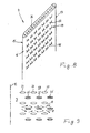
- FIG. 5 shows in a perspective view schematically a variant of the arrangement according to FIG. 4 for an approximately rectangular arrangement with respect to the end face 6 in the region of the longitudinal edges 16, 17 (FIG. 2), with comparatively the embodiment of FIG Longitudinal ribs 20, 21 and 20 ', 21' are arranged in pairs.
- the flat tubes 4, 4 'in the region of their front longitudinal edges 16 alternately each have a thick and a thin region 36, 34.
- the longitudinal ribs 20, 20 ', 21, 21' distributed in the direction of the longitudinal axis 10 from the material of the flat tubes 4, 4 'peeled-out transverse ribs 23 are provided.
- the mounting position of the flat tubes 4, 4 ' is selected with respect to the direction of the weight force 40 so that the transverse ribs 23 extend obliquely downwards in the direction of the force of gravity 40 and thus facilitate a drainage, for example, of condensed water.
- FIG. 6 shows a cross-sectional view of a further variant of flat tubes 4, 4 ', in which the associated longitudinal ribs 20, 21 or 20', 21 'are offset relative to one another.
- the width difference between the respective thin and thick regions 34, 36 is kept low.
- a meander-shaped air duct 37 is formed in which the flow direction of the second heating medium indicated by the arrows 8 alternately with a component lying in the plane E of the end surface 6 (FIG is charged. This will be an extension the flow path and an enlargement of the heat transferring surface achieved.
- Fig. 7 shows a further embodiment of a flat tube 4, from the flat side surfaces 15, 18 transversely to the longitudinal axis 10 extending transverse ribs 23 are peeled out as a means 19 for enlarging the heat-transmitting surface.
- the transverse ribs 23 have a corrugated edge 24, wherein the corrugated edge 24 may be in the plane of the transverse ribs 23 or perpendicular thereto.
- means 19 for enlarging the heat-transferring surface in the form of projections 22 are provided on its side surfaces 15, 18. 9 shows, in a sectional illustration through the projections 22, that in the spaces between them further projections 22 'of a not shown, adjacent flat tube 4' engage.
- the projections 22, 22 ' have to reduce the flow resistance on an aerodynamic cross-section, which is elliptical in the embodiment shown, but may also be oval, diamond-shaped or the like.
- the projections 22, 22 ' create a mutual division and merging of the air flow along the arrows 8 for improved mixing and for improved heat transfer.
- the deflected flow direction 8 has a component which increases the flow path and which lies parallel to the longitudinal axis 10.
- the flow direction 8 may comprise components which lie in any direction with respect to the plane E, and whereby an adapted Extension of the flow path for the heat medium 3 is made possible.
- the exemplary embodiments of flat tubes 4, 4 'shown in FIGS. 2 to 8 are manufactured in one piece from aluminum by means of extrusion and are designed as multi-chamber tubes with individual channels 26 for the first heat medium 2.
- flat tubes 4, 4 'shown in FIGS. 2 to 8 are manufactured in one piece from aluminum by means of extrusion and are designed as multi-chamber tubes with individual channels 26 for the first heat medium 2.
- sheet metal expedient either as a tube with welded longitudinal seam or as disk elements formed from sheet metal shells.
- FIG. 10 An embodiment of the latter form is shown in Fig. 10 schematically in cross section.
- the flat tubes 4, 4 ' are formed by two joined half-shells 43, 44 of sheet metal.
- the two half-shells 43, 44 are shaped such that in each case two chambers 45 are formed as channels 26 for the flow through the first heat medium 2.
- the direction of the block depth t corresponding to FIG. 1 is indicated by the arrow 42.
- a plurality of struts 41 are provided, which pass through the flat tubes 4, 4'.
- the struts 41 also form projections 22, 22 'in the sense of FIGS. 8 and 9, which extend from one side surface 15, 18 to the adjacent side surface 18', 15 '.
- the struts 41 both from the second heat medium 3 in the direction of arrows 8 as shown in FIG. 9 as Also flows through the first heat medium 2 within the channels 26 in the direction of the arrows 27 of FIG.
- the illustrated variants of surface and Strömungswegver Strukturrnden means 19 in the form of longitudinal ribs 20, 20 ', 21, 21' and in the form of projections 22 and transverse ribs 23 are integrally formed with the respective walls 25 of the flat tubes 4, 4 '.
- the projections 22, in particular in connection with the sheet-metal shell construction shown in Fig. 10 can be integrally formed by embossing the half-shells 43, 44. However, it may also be a separate production and subsequent attachment, for example by cohesive connection appropriate.
Landscapes
- Engineering & Computer Science (AREA)
- Physics & Mathematics (AREA)
- Thermal Sciences (AREA)
- Mechanical Engineering (AREA)
- General Engineering & Computer Science (AREA)
- Geometry (AREA)
- Heat-Exchange Devices With Radiators And Conduit Assemblies (AREA)
- Power Steering Mechanism (AREA)
- Compression-Type Refrigeration Machines With Reversible Cycles (AREA)
- Separation By Low-Temperature Treatments (AREA)
Abstract
Description
Die Erfindung betrifft einen Verdampfer einer Kraftfahrzeug-Klimaanlage mit den Merkmalen nach dem Oberbegriff des Anspruchs 1. Solche Verdampfer sind z.B. aus EP-A-0947792 bekannt.The invention relates to an evaporator of a motor vehicle air conditioner with the features according to the preamble of claim 1. Such evaporators are e.g. from EP-A-0947792.
Im Kraftfahrzeugen werden zunehmend komplexere Systeme eingesetzt, wodurch von dem insgesamt vorhandenen Bauraum für die einzelnen Komponenten ein immer kleinerer Anteil zur Verfügung steht. Dies betrifft insbesondere auch die Klimaanlagen, von denen einerseits eine hohe Leistung abverlangt wird, während andererseits der für die erforderlichen Wärmeübertrager zur Verfügung stehende Bauraum zunehmend eingeschränkt ist. Dies wirkt sich insbesondere bei Verdampfern begrenzter Blocktiefe nachteilig auf die Übertragungsleistung aus.In motor vehicles, increasingly complex systems are used, so that an ever smaller proportion of the overall installation space available for the individual components is available. This applies in particular to the air conditioning systems, on the one hand, a high performance is required, while on the other hand, the space available for the required heat exchanger space is increasingly limited. This has a detrimental effect on the transmission performance, especially in evaporators of limited block depth.
Wärmeübertrager der eingangs genannten Gattung weisen einen im wesentlichen aus parallel angeordneten Flachrohren gebildeten Block auf, wobei die Flachrohre von einem leicht verdampfenden Wärmemedium, nämlich einem Kältemittel, durchströmt sind. Dieser Block wird quer zu seiner Stirnfläche von einem zweiten Medium, im Regelfall Luft, durchströmt, wobei an der Oberfläche der Flachrohre ein Wärmeaustausch zwischen dem ersten und dem zweiten Wärmemedium stattfindet. Bei Verdampfern wird dabei die durch den Verdampfungsprozeß des ersten Wärmemediums entstehende Kälte durch die metallische Wandung der Flachrohre an die äußere Oberfläche geleitet und an die vorbeiströmende Luft übertragen, wodurch diese abgekühlte Luft zur Klimatisierung des Fahrzeuginnenraumes dient.Heat exchangers of the type mentioned have a substantially formed of parallel flat tubes block, wherein the flat tubes of a slightly evaporating heat medium, namely a refrigerant, flows through. This block is traversed transversely to its end face by a second medium, usually air, wherein on the surface of the flat tubes, a heat exchange between the first and the second heat medium takes place. In evaporators, the cold produced by the evaporation process of the first heat medium is conducted through the metallic wall of the flat tubes to the outer surface and to the air flowing past transferred, whereby this cooled air is used for air conditioning of the vehicle interior.
Das Bauvolumen des Wärmeübertragers setzt sich im wesentlichen aus der Stirnfläche und der Blocktiefe zusammen, wobei die Blocktiefe im wesentlichen der Tiefe der Flachrohre einer oder mehrerer Rohrreihen entspricht. Eine Möglichkeit der Reduktion des Bauvolumens besteht in der Verringerung der Blocktiefe, wodurch der Weg der den Block in Richtung der Blocktiefe durchströmenden Luft verkürzt wird. Zur Verbesserung der Wärmeübertragung sind eine Vielzahl von Lösungen bekannt, die im wesentlichen auf einer Vergrößerung der wärmeübertragenden Oberfläche basieren. Dazu sind auf der Oberfläche der Flachrohre, die dem Wärmemedium mit der geringeren Wärmekapazität zugewandt ist, hier also auf der Luftseite, oberflächenvergrößernde Einrichtungen wie Lamellen, Wellrippen oder dgl. vorgesehen. Derartige Maßnahmen sind jedoch bei entsprechend kompakten Bauformen des Wärmeübertragers und hoher Leistungsanforderung nicht ausreichend.The volume of the heat exchanger is composed essentially of the end face and the block depth, wherein the block depth substantially corresponds to the depth of the flat tubes of one or more rows of tubes. One way to reduce the volume of construction is to reduce the block depth, which shortens the path of the air flowing through the block in the direction of the block depth. To improve the heat transfer, a variety of solutions are known, which are based essentially on an increase in the heat-transmitting surface. These are on the surface of the flat tubes, which faces the heat medium with the lower heat capacity, so here on the air side, surface enlarging facilities such as fins, corrugated fins or the like. Provided. However, such measures are not sufficient with correspondingly compact designs of the heat exchanger and high power requirement.
Der Erfindung liegt die Aufgabe zugrunde, einen Verdampfer zu schaffen, bei dem das erforderliche Bauvolumen verringert ist.The invention has for its object to provide an evaporator, in which the required volume of construction is reduced.
Diese Aufgabe wird durch einen Verdampfer mit den Merkmalen des Anspruchs 1 gelöst.This object is achieved by an evaporator with the features of claim 1.
Dazu wird vorgeschlagen, in einem Wärmeübertrager der eingangs genannten Gattung die Flachrohre in Richtung der Blocktiefe mindestens über einen Teilabschnitt in einem Winkel zur Stirnfläche des Blockes anzuordnen. Der Winkel liegt dabei zweckmäßig etwa in einem Bereich zwischen 25° und 65° und beträgt insbesondere etwa 45°. Die zwischen den Flachrohren gebildeten Kanäle für die durchströmende Luft sind dabei etwa in gleichem Winkel gedreht, so daß die Strömungsrichtung der Luft zwischen den Flachrohren eine zur Stirnfläche geneigte Komponente aufweist. Durch die gegenüber der Anströmrichtung erfolgende Umlenkung der Strömungsrichtung im Bereich der Flachrohre wird dem Luftstrom innerhalb des Wärmeübertragerblocks ein Umweg aufgezwungen, in dessen Folge der Luftstrom mit einem verlängerten Weg an den Oberflächen der Flachrohre vorbeistreift. Durch die Wegverlängerung und der damit einhergehenden längeren Kontaktzeit kann der Luft bei einem Verdampfer mehr Wärme entzogen werden. Bei einer durch die Systemanforderungen vorgegebenen Wärmeübertragungsleistung kann deshalb der verfügbare Bauraum besser genutzt und insbesondere die Blocktiefe verringert werden.For this purpose, it is proposed to arrange in a heat exchanger of the type mentioned, the flat tubes in the direction of the block depth at least over a section at an angle to the end face of the block. The angle is expediently approximately in a range between 25 ° and 65 ° and is in particular about 45 °. The channels formed between the flat tubes for the air flowing through are rotated approximately at the same angle, so that the flow direction of the air between the flat tubes has a component inclined to the end face. By taking place opposite the direction of flow deflection of the flow direction in the region of the flat tubes, a detour is imposed on the air flow within the heat exchanger block, as a result of the air flow with an extended path on the surfaces of the flat tubes passes. By extending the path and the associated longer contact time of the air in an evaporator more heat can be withdrawn. At a given by the system requirements heat transfer performance therefore the available space can be better used and in particular the block depth can be reduced.
In einer vorteilhaften Variante oder auch in Kombination mit einer Schrägstellung weisen die Flachrohre einen Querschnitt etwa in Wellenform auf, wobei die konvexe Seite einer Welle eines Flachrohres in die konkave Seite der entsprechenden Welle des benachbarten Flachrohres mit Abstand eingreift. Dadurch ergeben sich in den Abständen zwischen den benachbarten Flachrohren wellenförmige Strömungskanäle für die Luft mit einem entsprechend verlängerten Strömungsweg bezogen auf die Blocktiefe. In einer vorteilhaften Variante ist die Wellenform etwa winklig, also beispielsweise in Treppenform ausgebildet. Dies erlaubt eine kostengünstige Fertigung mit einfachen Mitteln. In einer weiteren zweckmäßigen Variante ist die Wellenform gerundet ausgeführt, wodurch der Strömungswiderstand für die den Block durchströmende Luft gering gehalten ist. Zur weiteren Verringerung des Strömungswiderstandes ist die Wellenform derart ausgebildet, dass die Seitenflächen der Flachrohre im Bereich mindestens einer Längskante und insbesondere im Bereich beider Längskanten etwa senkrecht zur Stirnfläche stehen. Die anströmende und ggf. auch die abströmende Luft wird dadurch gerade in den Wärmetauscherblock hineingeführt bzw. aus ihm herausgelassen, wobei eine Umlenkung erst innerhalb des Wärmeblocks unter aerodynamisch gut definierten Bedingungen mit geringen Strömungsverlusten erfolgt.In an advantageous variant or in combination with an inclined position, the flat tubes have a cross-section approximately in the form of a wave, with the convex side of a shaft of a flat tube engaging in the concave side of the corresponding shaft of the adjacent flat tube at a distance. This results in the distances between the adjacent flat tubes wavy flow channels for the air with a correspondingly extended flow path based on the block depth. In an advantageous variant, the waveform is approximately angled, that is formed, for example, in staircase form. This allows a cost-effective production with simple means. In a further expedient variant, the waveform is rounded, whereby the flow resistance is kept low for the air flowing through the block. To further reduce the flow resistance is the Waveform formed such that the side surfaces of the flat tubes in the region of at least one longitudinal edge and in particular in the region of both longitudinal edges are approximately perpendicular to the end face. The inflowing and possibly also the outflowing air is thereby led straight into the heat exchanger block or let out of it, wherein a deflection takes place only within the heat block under aerodynamically well-defined conditions with low flow losses.
In einer vorteilhaften Weiterbildung weisen die Seitenflächen der Flachrohre Mittel zur Vergrößerung der wärmeübertragenden Oberfläche und/oder des Strömungsweges auf. In einer zweckmäßigen Variante dazu sind auf den Seitenflächen der Flachrohre in Richtung ihrer Längsachse liegende Längsrippen vorgesehen und derart versetzt zueinander angeordnet, dass die Längsrippen eines Flachrohres in die Zwischenräume der Längsrippen des benachbarten Flachrohres auf dessen angrenzender Seitenfläche eingreifen. Der dadurch entstehende wechselseitige Eingriff der Längsrippen erzeugt eine weitere etwa wellenförmige Umlenkung des Luftstromes entlang seines Weges in Tiefenrichtung des Wärmeübertragerblockes in Verbindung mit einer Vergrößerung der wärmeübertragenden Fläche. Dadurch ist eine weitere Verbesserung der Wärmeübertagungsleistung und damit bezogen auf eine vorgegebene Wärmeübertagungsleistung eine weitere Verringerung des Bauraumes ermöglicht.In an advantageous development, the side surfaces of the flat tubes have means for enlarging the heat-transmitting surface and / or the flow path. In an expedient variant, longitudinal ribs lying on the side surfaces of the flat tubes in the direction of their longitudinal axis are provided and arranged offset relative to one another such that the longitudinal ribs of a flat tube engage in the intermediate spaces of the longitudinal ribs of the adjacent flat tube on its adjacent side surface. The resulting mutual engagement of the longitudinal ribs generates a further approximately wave-shaped deflection of the air flow along its path in the depth direction of the heat exchanger block in conjunction with an enlargement of the heat-transferring surface. As a result, a further improvement of the heat transfer performance and thus based on a predetermined heat transfer performance a further reduction of the installation space is possible.
In einer zweckmäßigen Variante sind auf den Seitenflächen der Flachrohre diskrete Vorsprünge angeordnet, die ebenfalls wechselseitig in die Zwischenräume zwischen den Vorsprüngen des benachbarten Rohres eingreifen. Die Vorsprünge müssen außenseitig von der Luft umströmt werden.In an expedient variant discrete projections are arranged on the side surfaces of the flat tubes, which also mutually engage in the intermediate spaces between the projections of the adjacent tube. The projections must be surrounded on the outside by the air.
Dadurch entsteht eine vielfache Teilung und Zusammenführung des Luftstromes. Die Bildung einer laminaren Strömung wird verhindert und eine gute Durchmischung mit einem einhergehenden guten Wärmeübergang erzielt. Die Vorsprünge vergrößern darüber hinaus durch ihre Geome-trie bedingt die wärmeübertragende Oberfläche. Des weiteren erfolgt eine Strömungsumlenkung und damit eine Strömungswegverlängerung mit einer Komponente, die parallel zur Längsachse der Flachrohre liegt. Die genannten Vorsprünge weisen dabei zweckmäßig einen aerodynamischen Querschnitt beispielsweise in Form eines Ovales oder einer Ellipse auf, wodurch der Strömungswiderstand für die durchströmende Luft reduziert ist. In einer vorteilhaften Variante reichen die Vorsprünge von einer Außenseite eines Flachrohres zur benachbarten Außenseite des Nachbarflachrohres, wodurch sie auch als Abstandhalter dienen. Zur Vereinfachung der Fertigung und zur Verbesserung des Wärmeüberganges können Streben vorgesehen sein, die quer durch mehrere Flachrohre verlaufen. Ein Block von Flachrohren ist dabei auf diese Streben aufgefädelt, wobei die Streben als Montagehilfe dienen und die Flachrohre gegeneinander ausrichten. Darüber hinaus erfüllen die Streben die Funktion der oben beschriebenen Vorsprünge.This creates a multiple division and merging of the air flow. The formation of a laminar flow is prevented and achieved a good mixing with a concomitant good heat transfer. The projections also increase due to their Geome-trie conditionally the heat-transferring surface. Furthermore, there is a flow deflection and thus a flow path extension with a component which is parallel to the longitudinal axis of the flat tubes. The said projections expediently have an aerodynamic cross-section, for example in the form of an oval or an ellipse, whereby the flow resistance for the air flowing through is reduced. In an advantageous variant, the projections extend from one outer side of a flat tube to the adjacent outer side of the adjacent flat tube, whereby they also serve as spacers. To simplify the production and to improve the heat transfer struts may be provided which extend transversely through a plurality of flat tubes. A block of flat tubes is threaded onto these struts, the struts serve as an assembly aid and align the flat tubes against each other. In addition, the struts fulfill the function of the projections described above.
Die genannten Varianten der oberflächen- und strömungswegvergrößernden Mittel sind zweckmäßig einteilig mit einer Wand des Flachrohres ausgeführt.The mentioned variants of the surface and Strömungswegvergrößernden means are expediently made in one piece with a wall of the flat tube.
Zur weiteren Verbesserung der Wärmeübertagung können an den Seitenflächen des Flachrohres aus dessen Material herausgeschälte Querrippen vorgesehen sein. Diese Querrippen tragen zur Oberflächenvergrößerung bei, wobei durch den Prozeß des Herausschälens die Querrippen im Materialverbund mit dem Flachrohr bleiben mit einem einhergehenden, entsprechend guten Wärmeübergang. Als weitere Maßnahme zur Verbesserung des Wärmeübergangs können die Querrippen eine Kante in Wellenform aufweisen, wobei die Wellenform vergleichbar zum Wellenschliff eines Messers in der Querrippenebene liegen kann. In einer weiteren Variante liegt die Wellenform der Kante etwa senkrecht zur Oberfläche der Querrippe, wodurch auch diese eine strömungswegverlängernde Wirkung hat.To further improve the heat transfer can be provided on the side surfaces of the flat tube peeled out of the material transverse ribs. These transverse ribs contribute to the increase in surface area, wherein the transverse ribs in the material composite are formed by the process of peeling out stay with the flat tube with a corresponding, correspondingly good heat transfer. As a further measure for improving the heat transfer, the transverse ribs may have an edge in waveform, wherein the waveform may be comparable to the serrated edge of a knife in the transverse rib plane. In another variant, the waveform of the edge is approximately perpendicular to the surface of the transverse rib, whereby this also has a strömungswegverlängernde effect.
In einer vorteilhaften Weiterbildung sind die Flachrohre als Mehrkammerrohre mit einzelnen Kanälen für das erste Wärmemedium ausgebildet. Durch die Anordnung einer Vielzahl einzelner Kanäle ist einerseits die relative Oberfläche in Berührung mit dem ersten Wärmemedium vergrößert, wodurch auch in diesem Bereich ein verbesserter Wärmeübergang ermöglicht ist. Andererseits ist durch die Vielzahl voneinander getrennter Kanäle auch eine komplexe Strömungsführung innerhalb des Wärmeübertragerblocks ermöglicht. In einer zweckmäßigen Variante sind die Flachrohre aus einem Leichtmetall-Blech gefertigt, wodurch eine kostengünstige Fertigung auch unter Großserienbedingungen ermöglicht ist. Alternativ hierzu sind die Flachrohre im Extrusionsverfahren oder durch Fließpressen hergestellt, wozu Leichtmetall und insbesondere Aluminium nicht nur wegen des relativ geringen Gewichts, sondern gleichermaßen sowohl aus fertigungstechnischen Gesichtspunkten als auch wegen seiner guten Wärmeübertragungseigenschaften besonderes geeignet ist.In an advantageous development, the flat tubes are designed as multi-chamber tubes with individual channels for the first heat medium. By arranging a plurality of individual channels, on the one hand, the relative surface in contact with the first heating medium is increased, whereby an improved heat transfer is also made possible in this area. On the other hand, a complex flow guidance within the heat exchanger block is made possible by the plurality of separate channels. In an expedient variant, the flat tubes are made of a light metal sheet, whereby a cost-effective production is made possible even under high-volume conditions. Alternatively, the flat tubes are produced by extrusion or extrusion, including light metal and aluminum in particular not only because of the relatively low weight, but equally suitable both from manufacturing aspects and because of its good heat transfer properties.
Ausführungsbeispiele der Erfindung werden im folgenden anhand der Zeichnung näher erläutert. Es zeigen:
- Fig. 1
- in einer schematischen Übersichtsdarstellung einen Wärmeübertrager am Beispiel eines Verdampfers;
- Fig. 2
- eine Querschnittsdarstellung durch einen Verdampfer mit wellenförmigen Flachrohren und Längsrippen;
- Fig. 3
- eine schematische Querschnittsdarstellung von Flachrohren mit gerundeter Wellenform;
- Fig. 4
- eine Variante der Anordnung nach Fig. 3 mit paarweise gegenüberliegenden Längsrippen;
- Fig. 5
- in einer perspektivischen Darstellung eine weitere Variante von Flachrohren mit Längsrippen und geschälten Querrippen;
- Fig. 6
- eine schematische Querschnittsdarstellung durch Rohre mit gegeneinander versetzt angeordneten Längsrippen;
- Fig. 7
- in einer perspektivischen Darstellung ein Flach-rohr mit aus seiner Oberfläche geschälten, gewellten Querrippen;
- Fig. 8
- eine Variante der Anordnung nach Fig. 7 mit einer Vielzahl von strömungsumleitenden Vorsprüngen;
- Fig. 9
- eine Querschnittsdarstellung durch ineinandergreifende Vorsprünge nach Fig. 8 zweier benachbarter Flachrohre;
- Fig. 10
- eine Prinzipdarstellung eines Querschnittes durch Flachrohre in Blechschalenbauweise mit durchlaufenden Streben.
- Fig. 1
- in a schematic overview representation of a heat exchanger using the example of an evaporator;
- Fig. 2
- a cross-sectional view through an evaporator with wave-shaped flat tubes and longitudinal ribs;
- Fig. 3
- a schematic cross-sectional view of flat tubes with rounded waveform;
- Fig. 4
- a variant of the arrangement of Figure 3 with pairwise opposed longitudinal ribs.
- Fig. 5
- in a perspective view of another variant of flat tubes with longitudinal ribs and shelled transverse ribs;
- Fig. 6
- a schematic cross-sectional view through tubes with mutually staggered longitudinal ribs;
- Fig. 7
- in a perspective view of a flat-tube with peeled from its surface, corrugated transverse ribs;
- Fig. 8
- a variant of the arrangement of Figure 7 with a plurality of Strömungsumleitenden projections.
- Fig. 9
- a cross-sectional view through interlocking projections of Figure 8 of two adjacent flat tubes ..;
- Fig. 10
- a schematic diagram of a cross section through flat tubes in sheet metal shell construction with continuous struts.
Fig. 1 zeigt in einer schematischen Übersichtsdarstellung einen Wärmeübertrager einer Klimaanlage eines Kraftfahrzeuges am Beispiel eines Verdampfers 1. Auch ein zur Klimaanlage gehöriger Kondensator kann in erfindungsgemäßer, nachfolgend beschriebener Weise ausgeführt sein. Der Verdampfer 1 umfaßt eine Vielzahl von Flachrohren 4, 4', die im wesentlichen parallel zueinander liegend in Form eines Blockes 5 zusammengefaßt sind. Die Flachrohre 4, 4' sind an ihren beiden Enden jeweils mit einem Sammelkasten 29, 30 strömungsleitend verbunden. Der obere Sammelkasten 29 ist durch insgesamt vier Trennwände 31 in insgesamt vier Teilräume 38 aufgeteilt, während der untere Sammelkasten 30 mittels einer Trennwand 32 in zwei Teilräume 39 aufgeteilt ist. Ein leicht verdampfliches erstes Wärmemedium 2 durchströmt die Flachrohre 4, 4' entlang der Pfeile 27, wobei die Anordnung der Trennwände 31, 32 eine Durchströmung der Flachrohre 4, 4' in Form eines Kreuzgegenstromes ergibt. Je nach Anwendungsfall kann auch eine Ausbildung des Verdampfers 1 mit anderer Strömungspaarung, beispielsweise einem reinen Kreuzstrom zweckmäßig sein.1 shows a schematic overview of a heat exchanger of an air conditioning system of a motor vehicle, using the example of an evaporator 1. A condenser belonging to the air conditioning system can also be designed according to the invention, described below. The evaporator 1 comprises a plurality of
Die blockförmige Anordnung der Flachrohre 4, 4' ergibt im Bereich ihrer Längskanten 16 eine Stirnfläche 6, die in einer gestrichelt angedeuteten Ebene E liegt. Senkrecht zur Stirnfläche 6 bzw. zur Ebene E weist der Block 5 eine Blocktiefe t auf. Der Block 5 wird von einem zweiten Strömungsmedium 3 in der durch den Pfeil 7 angedeuteten Strömungsrichtung durchströmt, wobei die Strömungsrichtung 7 im wesentlichen quer zur Stirnfläche 6 liegt. Das zweite Wärmemedium 3 ist die durch den Verdampfer 5 zu kühlende Luft. Beim Durchströmen des Blockes 5 tritt das zweite Wärmemedium 3 zunächst im Bereich der vorderen Längskanten 16 in den Block 5 ein und wird anschließend zwischen den Flachrohren 4, 4' an deren Oberflächen 17, 18 für einen Wärmeaustausch vorbeigeführt. Anschließend verlässt das zweite Wärmemedium den Verdampfer 1 im Bereich der hinteren Längskanten 17 der Flachrohre 4, 4'.The block-shaped arrangement of the
Fig. 2 zeigt ausschnittsweise eine Querschnittsdarstellung durch einen Block 5 (Fig. 1), bei dem eine Vielzahl parallel zueinander angeordneter Flachrohre 4, 4' vorgesehen ist, die sich in Richtung der Blocktiefe t jeweils von einer vorderen Längskante 16 zu einer hinteren Längskante 17 erstrecken. Die Flachrohre 4, 4' verlaufen in Richtung der Blocktiefe t im Bereich ihres mittleren Teilabschnittes in einem Winkel α von etwa 45° zur Stirnfläche des Blockes 5. Durch die Schrägstellung erhält das zweite Wärmemedium 3 zwischen den Flachrohren 4, 4' eine umgelenkte Strömungsrichtung 8, die eine geneigt zur Stirnfläche 6 und quer zur Längsachse 10 liegende Komponente aufweist. Dadurch wird der Strömungsweg entlang der umgelenkten Strömungsrichtung 8 zwischen der vorderen Längskante 6 und der hinteren Längskante 17 länger als die Blocktiefe t. Durch die Anordnung eines Füllkörpers 28 seitlich des äußersten Flachrohres 4" wird auch am äußersten Flachrohr eine anliegende Strömung sichergestellt. Die Flachrohre 4, 4', 4" weisen in ihrem Querschnitt eine etwa eckig ausgebildete Wellenform mit jeweils einer Welle 13 im Bereich der vorderen und der hinteren Längskante 16, 17 auf. Die beiden Wellen 13 sind derart ausgebildet, dass die beiden Seitenflächen 15, 18 der Flachrohre 4, 4', 4" im Bereich der Längskanten 16, 17 etwa senkrecht zur Stirnfläche 6 stehen. Die Flachrohre 4, 4', 4" weisen des weiteren auf ihren beiden Seitenflächen 15, 17 etwa parallel zur Längsachse 10 verlaufende Längsrippen 20, 20', 21, 21' auf, die mit Abstand ineinander eingreifen. Die dadurch entstehende umgelenkte Strömungsrichtung 8 ist im Zusammenhang mit Fig. 6 weiter unten näher beschrieben.Fig. 2 shows a detail of a cross-sectional view through a block 5 (Fig. 1), in which a plurality of mutually parallel
Bei der in Fig. 3 gezeigten Variante von Flachrohren 4, 4' weisen diese in ihrem gezeigten Querschnitt eine gerundete Wellenform mit jeweils einer gerundeten Welle 13 im Bereich der vorderen und hinteren Längskanten 16, 17 auf. Dabei greift jeweils die konvexe Seite 12 einer Welle 13 eines Flachrohres 4 in die konkave Seite 14 der entsprechenden Welle 13 des benachbarten Flachrohres 4' mit Abstand ein. Die quer zur Ebene E entlang der Strömungsrichtung 7 einströmende Luft wird zwischen den Flachrohren 4, 4' in eine Strömungsrichtung 8 derart umgelenkt, dass die Strömungsrichtung 8 eine Komponente geneigt zur Ebene E aufweist.In the variant of
Die in Fig. 4 gezeigte Variante von Flachrohren 4, 4' weist an ihren Seitenflächen 15, 15', 18, 18' Mittel 19 zur Vergrößerung der wärmeübertragenden Fläche der Flachrohre 4, 4' und des Strömungsweges des zweiten Wärmemediums 3 auf. Im gezeigten Ausführungsbeispiel bestehen die Mittel 19 aus einer Anzahl von parallel zur Längsachse 10 (Fig. 1, 2) angeordneten Längsrippen 20, 20', 21, 21'. Im gezeigten Ausführungsbeispiel sind die Längsrippen 20, 21 bzw. die Längsrippen 20', 21' des entsprechenden Flachrohres 4, 4' paarweise gegenüber liegend angeordnet. Dadurch entsteht im Bereich der Längsrippen 20, 21, bzw. 20', 21' ein dicker Bereich 36, während die Flachrohre 4, 4' im Bereich dazwischen einen dünnen Bereich 34 aufweisen. Die Flachrohre 4, 4' weisen eine abgewinkelte Wellenform mit jeweils einer mittigen Wellenspitze 13 auf. Die Wellenform ist symmetrisch, so daß die vorderen und hinteren Längskanten 16, 17 der Flachrohre auf einer Linie in der durch einen Pfeil 42 dargestellten Blocktiefenrichtung liegen. Die vorderen und hinteren Teilabschnitte der Flachrohre 4, 4' beiderseitig der Wellenspitze 13 sind bezüglich der Ebene E derart schräg gestellt angeordnet, dass wechselseitig jeweils eine Längsrippe 20', 21 in den gegenüber liegenden Zwischenraum 35 eingreift.The variant of
Zur Verringerung des Strömungswiderstandes für das eintretende zweite Wärmemedium 3 entlang der Strömungsrichtung 7 weisen die Flachrohre 4, 4' im Bereich ihrer Längskante 16 einen dünnen Bereich 34 auf. Durch den wechselseitigen Eingriff der Längsrippen 20', 21 in die gegenüberliegenden Zwischenräume 35 entsteht ein den Strömungsweg verlängernder, in Zusammenhang mit Fig. 6 näher beschriebener mäanderförmiger Strömungsweg.To reduce the flow resistance for the incoming
Die Flachrohre 4, 4' weisen eine identische Bauform auf, wobei durch die Schrägstellung bezüglich der Ebene E trotz der kostensparenden identischen Ausführung und der paarweise gegenüberliegenden Längsrippen 20, 21 bzw. 20', 21' ihr wechselseitiger Eingriff in die gegenüberliegenden Zwischenräume 35 ermöglicht ist. Neben der Strömungsumlenkung im Bereich der Längsrippen 20, 20', 21, 21' und den zugehörigen Zwischenräumen 35 führt auch die Schrägstellung der Flachrohre 4, 4' zu einer kombinierten Vergrößerung des Strömungsweges des zweiten Wärmemediums 3 und zu einer Vergrößerung der wärmeübertragenden Oberfläche an den Flachrohren 4, 4'.The
Fig. 5 zeigt in einer perspektivischen Darstellung schematisch eine Variante der Anordnung nach Fig. 4 zur etwa rechtwinkligen Anordnung bezüglich der Stirnfläche 6 im Bereich der Längskanten 16, 17 (Fig. 2), wobei ver-gleichbar zum Ausführungsbeispiel nach Fig. 5 gerundet ausgeführte Längsrippen 20, 21 bzw. 20', 21' jeweils paarweise angeordnet sind. Um ihren wechselseitigen Eingriff in die gegenüberliegenden Zwischenräume 35 zu ermöglichen, weisen die Flachrohre 4, 4' im Bereich ihrer vorderen Längskanten 16 abwechselnd jeweils einen dicken und einen dünnen Bereich 36, 34 auf. An den Längsrippen 20, 20', 21, 21' sind in Richtung der Längsachse 10 verteilt aus dem Material der Flachrohre 4, 4' herausgeschälte Querrippen 23 vorgesehen. Die Einbaulage der Flachrohre 4, 4' ist dabei bezüglich der Gewichtskraftrichtung 40 so gewählt, dass die Querrippen 23 schräg nach unten in Gewichtskraftrichtung 40 verlaufen und damit ein Abtropfen beispielsweise von Kondenswasser erleichtern.5 shows in a perspective view schematically a variant of the arrangement according to FIG. 4 for an approximately rectangular arrangement with respect to the
Fig. 6 zeigt in einer Querschnittsdarstellung eine weitere Variante von Flachrohren 4, 4', bei denen die zugehörigen Längsrippen 20, 21 bzw. 20', 21' gegeneinander versetzt angeordnet sind. Bei dieser Variante ist der Breitenunterschied zwischen den jeweiligen dünnen und dicken Bereichen 34, 36 gering gehalten. Durch den wechselseitigen Eingriff der Längsrippen 21, 20' in die gegenüberliegenden Zwischenräume 35 entsteht ein mäanderförmiger Luftkanal 37, in dem die durch die Pfeile 8 gekennzeichnete Strömungsrichtung des zweiten Wärmemediums wechselnd mit einer in der Ebene E der Stirnfläche 6 (Fig. 1) liegenden Komponente beaufschlagt wird. Dadurch wird eine Verlängerung des Strömungsweges und eine Vergrößerung der wärmeübertragenden Oberfläche erzielt.6 shows a cross-sectional view of a further variant of
Fig. 7 zeigt ein weiteres Ausführungsbeispiel eines Flachrohres 4, aus dessen ebenen Seitenflächen 15, 18 quer zur Längsachse 10 verlaufende Querrippen 23 als Mittel 19 zur Vergrößerung der wärmeübertragenden Oberfläche herausgeschält sind. Die Querrippen 23 weisen eine gewellte Kante 24 auf, wobei die Wellenform der gewellten Kante 24 in der Ebene der Querrippen 23 oder senkrecht dazu liegen kann.Fig. 7 shows a further embodiment of a
Bei der in Fig. 8 gezeigten Ausführung eines Flachrohres 4 sind auf dessen Seitenflächen 15, 18 Mittel 19 zur Vergrößerung der wärmeübertragenden Oberfläche in Form von Vorsprüngen 22 vorgesehen. Fig. 9 zeigt dazu in einer Schnittdarstellung durch die Vorsprünge 22, dass in deren Zwischenräume weitere Vorsprünge 22' eines nicht näher dargestellten, benachbarten Flachrohres 4' ein-greifen. Die Vorsprünge 22, 22' weisen zur Verringerung des Strömungswiderstandes einen aerodynamischen Querschnitt auf, der im gezeigten Ausführungsbeispiel elliptisch ist, bedarfsweise aber auch oval, rautenförmig oder dgl. sein kann. Die Vorsprünge 22, 22' erzeugen eine wechselseitige Teilung und Zusammenführung des Luftstromes entlang der Pfeile 8 für eine verbesserte Durchmischung und für eine verbesserte Wärmeübertragung. Die umgelenkte Strömungsrichtung 8 weist eine den Strömungsweg vergrößernde Komponente auf, die parallel zur Längsachse 10 liegt. In Verbindung mit einer Schrägstellung der Flachrohre 4, 4', oder einer wellenförmigen Ausbildung entsprechend den zuvor gezeigten Ausführungsbeispielen kann die Strömungsrichtung 8 Komponenten aufweisen, die in beliebiger Richtung bezüglich der Ebene E liegen, und wodurch eine angepasste Verlängerung des Strömungsweges für das Wärmemedium 3 ermöglicht ist.In the embodiment of a
Die in den Fig. 2 bis 8 gezeigten Ausführungsbeispiele von Flachrohren 4, 4' sind einteilig aus Aluminium auf dem Wege des Fließpressens hergestellt und als Mehrkammerrohre mit einzelnen Kanälen 26 für das erste Wärmemedium 2 ausgebildet. Für bestimmte Querschnittsformen kommen auch extrudierte Flachrohre in Betracht. Es kann jedoch auch eine Ausführung aus Blech zweckmäßig sein, entweder als Rohr mit geschweißter Längsnaht oder als aus Blechschalen gebildete Scheibenelemente.The exemplary embodiments of
Ein Ausführungsbeispiel zu letztgenannter Form ist in Fig. 10 schematisch im Querschnitt gezeigt. Die Flachrohre 4, 4' sind durch zwei zusammengefügte Halbschalen 43, 44 aus Blech gebildet. Die beiden Halbschalen 43, 44 sind derart geformt, daß jeweils zwei Kammern 45 als Kanäle 26 zur Durchströmung durch das erste Wärmemedium 2 gebildet sind. Je nach Anwendungsfall können auch Ausbildungen mit einer oder mehreren Kammern 45 zweckmäßig sein. Die Richtung der Blocktiefe t entsprechend Fig. 1 ist durch den Pfeil 42 angegeben. Die Flachrohre 4, 4' verlaufen bezüglich des Pfeiles 42 in einem Winkel α von etwa 45°. Als Abstandhalter und Montagehilfe für die Flachrohre 4, 4' sowie als Mittel 19 zur Vergrößerung der wärmeübertragenden Fläche sind eine Vielzahl von Streben 41 vorgesehen, die die Flachrohre 4, 4' durchgreifen. Dabei bilden die Streben 41 auch Vorsprünge 22, 22' im Sinne der Fig. 8 und 9, welche von einer Seitenfläche 15, 18 bis zur benachbarten Seitenfläche 18', 15' verlaufen. Zur Verbesserung des Wärmeüberganges werden die Streben 41 sowohl vom zweiten Wärmemedium 3 in Richtung der Pfeile 8 entsprechend Fig. 9 als auch durch das erste Wärmemedium 2 innerhalb der Kanäle 26 in Richtung der Pfeile 27 nach Fig. 1 umströmt.An embodiment of the latter form is shown in Fig. 10 schematically in cross section. The
Die gezeigten Varianten von oberflächen- und strömungswegvergrößernden Mitteln 19 in Form von Längsrippen 20, 20', 21, 21' sowie in Form von Vorsprüngen 22 und Querrippen 23 sind einteilig mit den jeweiligen Wänden 25 der Flachrohre 4, 4' ausgebildet. Die Vorsprünge 22 können insbesondere in Verbindung mit der in Fig. 10 gezeigten Blechschalenbauweise einteilig durch Prägung der Halbschalen 43, 44 geformt sein. Es kann jedoch auch eine separate Fertigung und eine anschließende Befestigung beispielsweise durch stoffschlüssige Verbindung zweckmäßig sein.The illustrated variants of surface and Strömungswegvergrößernden means 19 in the form of
Claims (16)
- An evaporator of an air conditioning system in a motor vehicle for transferring heat between a first and a second heat medium (2, 3) having a number of flat tubes (4, 4') forming a block (5) through which the first heat medium (2) flows and which are positioned essentially parallel to one another thereby forming ducts for the second heat medium (3) which enters at a front face (6) of the block (5) between neighbouring flat tubes (4, 4'), the front face (6) lying at right angles to a direction of flow (7) of the second heat medium (3),
characterised in that
the flat pipes (4, 4') run along the depth of the block (t) at an angle (α) to the front face (6) of the block (5) over at least a part section, the angle (α) lying approximately in a range between 25° and 65°. - An evaporator in accordance with claim 1,
characterised in that
the angle (α) is approximately 45°. - An evaporator in accordance with claim 1 or 2,
characterised in that
the flat tubes (4, 4') have an approximately wave-shaped cross-section (11). - An evaporator in accordance with claim 3,
characterised in that
the wave shape is somewhat angular. - An evaporator in accordance with claim 3,
c h a r a c t e r i s e d i n that
the wave shape is rounded. - An evaporator in accordance with one of claims 3 to 5,
characterised in that
the wave shape is such that the lateral faces (15, 18) of the flat tube (4) lie adjacent to a longitudinal edge (16, 17) and in particular in immediate contact with both longitudinal edges (16, 17) approximately perpendicular to the front face (6). - An evaporator in accordance with one of claims 1 to 6,
characterised in that
the lateral faces (15, 15', 18, 18') of the flat tubes (4, 4') have means (19) of increasing the heat-transferririg surface and/or the flow path of the second heat medium (3). - An evaporator in accordance with claim 7,
characterised in that
the means (19) are formed in one piece with a wall (25) of the flat tube (4). - An evaporator in accordance with claim 7 or 8,
characterised in that
on two adjacent lateral faces (15', 18) the flat tubes (4, 4') have longitudinal ribs (20, 20', 21, 21') which are offset in relation to one another. - An evaporator in accordance with one of claims 7 to 9,
characterised in that
provided on the lateral faces (15, 15', 18, 18') are projections (22, 22'), in particular with an aerodynamic cross-section. - An evaporator in accordance with claim 10,
c h a r a c t e r i s e d in that
the projections (22, 22') run from one lateral face (18, 15) to the neighbouring lateral face (15' 18') of the subsequent flat tube (4, 4') and in particular are designed as struts (41) which pass through several flat tubes (4, 4'). - An evaporator in accordance with claim 8 or 9,
characterised in that
provided on the lateral faces (15, 18) are transverse ribs (23) which are scooped out of the material of the flat tube (4). - An evaporator in accordance with claim 12,
characterised in that
the transverse ribs (23) have corrugated edges (24). - An evaporator in accordance with one of claims 1 to 13,
characterised in that
the flat tubes (4, 4') are designed as multi-chamber tubes with individual channels (26) for the first heat medium (2). - An evaporator in accordance with one of claims 1 to 14,
characterised in that
the flat tubes (4, 4') are made of a light sheet metal. - An evaporator in accordance with one of claims 1 to 14,
characterised in that
the flat tubes (4, 4') are made by the extrusion of a light metal, in particular aluminium or an aluminium alloy.
Applications Claiming Priority (2)
| Application Number | Priority Date | Filing Date | Title |
|---|---|---|---|
| DE10115513A DE10115513A1 (en) | 2001-03-28 | 2001-03-28 | Heat exchanger |
| DE10115513 | 2001-03-28 |
Publications (2)
| Publication Number | Publication Date |
|---|---|
| EP1248063A1 EP1248063A1 (en) | 2002-10-09 |
| EP1248063B1 true EP1248063B1 (en) | 2006-06-28 |
Family
ID=7679518
Family Applications (1)
| Application Number | Title | Priority Date | Filing Date |
|---|---|---|---|
| EP02006050A Expired - Lifetime EP1248063B1 (en) | 2001-03-28 | 2002-03-16 | Heat exchanger |
Country Status (3)
| Country | Link |
|---|---|
| EP (1) | EP1248063B1 (en) |
| AT (1) | ATE331928T1 (en) |
| DE (2) | DE10115513A1 (en) |
Families Citing this family (6)
| Publication number | Priority date | Publication date | Assignee | Title |
|---|---|---|---|---|
| JPWO2005073655A1 (en) * | 2004-01-29 | 2007-09-13 | カルソニックカンセイ株式会社 | Heat exchanger and air conditioner including the same |
| DE202010010187U1 (en) * | 2010-07-14 | 2010-10-14 | Erbslöh Aluminium Gmbh | Hollow profile for heat exchangers |
| EP2788705B1 (en) * | 2011-12-08 | 2017-03-01 | Carrier Corporation | Method of forming heat exchanger tubes |
| US11662148B2 (en) | 2017-08-03 | 2023-05-30 | Mitsubishi Electric Corporation | Heat exchanger and refrigeration cycle apparatus |
| DE102018131026A1 (en) | 2018-12-05 | 2020-06-10 | Volkswagen Aktiengesellschaft | Heat exchanger for a vehicle, in particular an electric vehicle |
| FR3104690B1 (en) * | 2019-12-13 | 2022-08-26 | Valeo Systemes Thermiques | Heat exchanger and method of manufacturing such an exchanger |
Family Cites Families (12)
| Publication number | Priority date | Publication date | Assignee | Title |
|---|---|---|---|---|
| DE166135C (en) * | ||||
| FR685849A (en) * | 1929-11-30 | 1930-07-17 | Radiator for automobile engines | |
| NL7202072A (en) * | 1972-02-17 | 1973-08-21 | ||
| US4024623A (en) * | 1973-06-21 | 1977-05-24 | Union Carbide Corporation | Manufacture of isostress contoured dies |
| NL7314930A (en) * | 1973-10-31 | 1975-05-02 | Philips Nv | HEAT EXCHANGER. |
| JPS6341791A (en) * | 1986-08-06 | 1988-02-23 | Komatsu Ltd | Skived-finned heat exchanger |
| DE3813339C2 (en) * | 1988-04-21 | 1997-07-24 | Gea Happel Klimatechnik | Heat exchangers for motor vehicles and process for its manufacture |
| FR2709816B1 (en) * | 1993-09-07 | 1995-10-13 | Valeo Thermique Moteur Sa | Brazed heat exchanger useful in particular as an air conditioning condenser for vehicles. |
| DE19719260C1 (en) * | 1997-05-07 | 1998-09-24 | Valeo Klimatech Gmbh & Co Kg | Extruded flat form heat exchanger for motor vehicle |
| DE19740114A1 (en) * | 1997-09-12 | 1999-03-18 | Behr Gmbh & Co | Heat exchanger, e.g. for motor vehicles |
| DE19845336A1 (en) * | 1998-10-01 | 2000-04-06 | Behr Gmbh & Co | Multi-channel flat tube |
| AU2001286552A1 (en) * | 2000-08-21 | 2002-03-04 | Engineered Dynamics Corporation | Heat exchanger assembly and a method for efficiently transferring heat |
-
2001
- 2001-03-28 DE DE10115513A patent/DE10115513A1/en not_active Withdrawn
-
2002
- 2002-03-16 DE DE50207351T patent/DE50207351D1/en not_active Expired - Lifetime
- 2002-03-16 EP EP02006050A patent/EP1248063B1/en not_active Expired - Lifetime
- 2002-03-16 AT AT02006050T patent/ATE331928T1/en not_active IP Right Cessation
Also Published As
| Publication number | Publication date |
|---|---|
| EP1248063A1 (en) | 2002-10-09 |
| DE50207351D1 (en) | 2006-08-10 |
| ATE331928T1 (en) | 2006-07-15 |
| DE10115513A1 (en) | 2002-10-10 |
Similar Documents
| Publication | Publication Date | Title |
|---|---|---|
| DE19719252C2 (en) | Double-flow and single-row brazed flat tube evaporator for a motor vehicle air conditioning system | |
| DE69031047T2 (en) | Evaporators for coolers in motor vehicles | |
| EP0401752B1 (en) | Refrigerant condensor for a vehicle air conditioner | |
| EP1036296B1 (en) | Flat tube with transversally offset u-bend section and heat exchanger configured using same | |
| DE3856032T3 (en) | Heat exchanger with improved condensate collection | |
| DE60319986T2 (en) | Plate heat exchanger | |
| DE69911131T2 (en) | heat exchangers | |
| EP0845647B1 (en) | Flat tube heat exchanger with twisted tube ends | |
| EP1701125A2 (en) | Heat exchanger with flat tubes and flat tube for heat exchanger | |
| DE112005003151T5 (en) | Evaporator | |
| WO2005088219A1 (en) | Heat exchanger for a motor vehicle air conditioning system | |
| DE112005001009T5 (en) | heat exchangers | |
| DE112006000179T5 (en) | heat exchangers | |
| DE112005001700T5 (en) | heat exchangers | |
| DE112005001699T5 (en) | heat exchangers | |
| EP1203922A2 (en) | Condenser and tube therefor | |
| DE112005001295T5 (en) | heat exchangers | |
| EP1411310B1 (en) | Heat exhanger with serpentine structure | |
| DE10257767A1 (en) | Heat exchanger for condenser or gas cooler for air conditioning installations has two rows of channels for coolant with manifolds at ends and has ribs over which air can flow | |
| DE19719256A1 (en) | Multi-flow flat tube heat exchanger for motor vehicles with a deflecting base and manufacturing process | |
| DE19933913A1 (en) | Evaporator of an automotive air conditioning system | |
| EP0582835A1 (en) | Heat-exchanger | |
| EP1664655B1 (en) | Heat exchanger | |
| DE102006032570A1 (en) | Heat exchanger unit for air conditioning system of motor vehicle, has internal heat exchanger directly connected or soldered with heat exchanger over connecting cable for formation of structural unit | |
| EP1248063B1 (en) | Heat exchanger |
Legal Events
| Date | Code | Title | Description |
|---|---|---|---|
| PUAI | Public reference made under article 153(3) epc to a published international application that has entered the european phase |
Free format text: ORIGINAL CODE: 0009012 |
|
| AK | Designated contracting states |
Kind code of ref document: A1 Designated state(s): AT BE CH CY DE DK ES FI FR GB GR IE IT LI LU MC NL PT SE TR |
|
| AX | Request for extension of the european patent |
Free format text: AL;LT;LV;MK;RO;SI |
|
| 17P | Request for examination filed |
Effective date: 20030401 |
|
| AKX | Designation fees paid |
Designated state(s): AT BE CH CY DE DK ES FI FR GB GR IE IT LI LU MC NL PT SE TR |
|
| RAP1 | Party data changed (applicant data changed or rights of an application transferred) |
Owner name: BEHR GMBH & CO. KG |
|
| 17Q | First examination report despatched |
Effective date: 20050309 |
|
| GRAP | Despatch of communication of intention to grant a patent |
Free format text: ORIGINAL CODE: EPIDOSNIGR1 |
|
| GRAS | Grant fee paid |
Free format text: ORIGINAL CODE: EPIDOSNIGR3 |
|
| GRAA | (expected) grant |
Free format text: ORIGINAL CODE: 0009210 |
|
| AK | Designated contracting states |
Kind code of ref document: B1 Designated state(s): AT BE CH CY DE DK ES FI FR GB GR IE IT LI LU MC NL PT SE TR |
|
| PG25 | Lapsed in a contracting state [announced via postgrant information from national office to epo] |
Ref country code: IT Free format text: LAPSE BECAUSE OF FAILURE TO SUBMIT A TRANSLATION OF THE DESCRIPTION OR TO PAY THE FEE WITHIN THE PRESCRIBED TIME-LIMIT;WARNING: LAPSES OF ITALIAN PATENTS WITH EFFECTIVE DATE BEFORE 2007 MAY HAVE OCCURRED AT ANY TIME BEFORE 2007. THE CORRECT EFFECTIVE DATE MAY BE DIFFERENT FROM THE ONE RECORDED. Effective date: 20060628 Ref country code: IE Free format text: LAPSE BECAUSE OF FAILURE TO SUBMIT A TRANSLATION OF THE DESCRIPTION OR TO PAY THE FEE WITHIN THE PRESCRIBED TIME-LIMIT Effective date: 20060628 Ref country code: NL Free format text: LAPSE BECAUSE OF FAILURE TO SUBMIT A TRANSLATION OF THE DESCRIPTION OR TO PAY THE FEE WITHIN THE PRESCRIBED TIME-LIMIT Effective date: 20060628 Ref country code: FI Free format text: LAPSE BECAUSE OF FAILURE TO SUBMIT A TRANSLATION OF THE DESCRIPTION OR TO PAY THE FEE WITHIN THE PRESCRIBED TIME-LIMIT Effective date: 20060628 |
|
| REG | Reference to a national code |
Ref country code: GB Ref legal event code: FG4D Free format text: NOT ENGLISH |
|
| REG | Reference to a national code |
Ref country code: CH Ref legal event code: EP |
|
| REG | Reference to a national code |
Ref country code: IE Ref legal event code: FG4D Free format text: LANGUAGE OF EP DOCUMENT: GERMAN |
|
| REF | Corresponds to: |
Ref document number: 50207351 Country of ref document: DE Date of ref document: 20060810 Kind code of ref document: P |
|
| GBT | Gb: translation of ep patent filed (gb section 77(6)(a)/1977) |
Effective date: 20060904 |
|
| PG25 | Lapsed in a contracting state [announced via postgrant information from national office to epo] |
Ref country code: DK Free format text: LAPSE BECAUSE OF FAILURE TO SUBMIT A TRANSLATION OF THE DESCRIPTION OR TO PAY THE FEE WITHIN THE PRESCRIBED TIME-LIMIT Effective date: 20060928 |
|
| PG25 | Lapsed in a contracting state [announced via postgrant information from national office to epo] |
Ref country code: ES Free format text: LAPSE BECAUSE OF FAILURE TO SUBMIT A TRANSLATION OF THE DESCRIPTION OR TO PAY THE FEE WITHIN THE PRESCRIBED TIME-LIMIT Effective date: 20061009 |
|
| REG | Reference to a national code |
Ref country code: SE Ref legal event code: TRGR |
|
| ET | Fr: translation filed | ||
| PG25 | Lapsed in a contracting state [announced via postgrant information from national office to epo] |
Ref country code: PT Free format text: LAPSE BECAUSE OF FAILURE TO SUBMIT A TRANSLATION OF THE DESCRIPTION OR TO PAY THE FEE WITHIN THE PRESCRIBED TIME-LIMIT Effective date: 20061128 |
|
| NLV1 | Nl: lapsed or annulled due to failure to fulfill the requirements of art. 29p and 29m of the patents act | ||
| REG | Reference to a national code |
Ref country code: IE Ref legal event code: FD4D |
|
| PLBE | No opposition filed within time limit |
Free format text: ORIGINAL CODE: 0009261 |
|
| STAA | Information on the status of an ep patent application or granted ep patent |
Free format text: STATUS: NO OPPOSITION FILED WITHIN TIME LIMIT |
|
| 26N | No opposition filed |
Effective date: 20070329 |
|
| REG | Reference to a national code |
Ref country code: CH Ref legal event code: PL |
|
| BERE | Be: lapsed |
Owner name: BEHR G.M.B.H. & CO. KG Effective date: 20070331 |
|
| PG25 | Lapsed in a contracting state [announced via postgrant information from national office to epo] |
Ref country code: BE Free format text: LAPSE BECAUSE OF NON-PAYMENT OF DUE FEES Effective date: 20070331 |
|
| PG25 | Lapsed in a contracting state [announced via postgrant information from national office to epo] |
Ref country code: MC Free format text: LAPSE BECAUSE OF NON-PAYMENT OF DUE FEES Effective date: 20070331 |
|
| PG25 | Lapsed in a contracting state [announced via postgrant information from national office to epo] |
Ref country code: LI Free format text: LAPSE BECAUSE OF NON-PAYMENT OF DUE FEES Effective date: 20070331 Ref country code: CH Free format text: LAPSE BECAUSE OF NON-PAYMENT OF DUE FEES Effective date: 20070331 |
|
| PG25 | Lapsed in a contracting state [announced via postgrant information from national office to epo] |
Ref country code: GR Free format text: LAPSE BECAUSE OF FAILURE TO SUBMIT A TRANSLATION OF THE DESCRIPTION OR TO PAY THE FEE WITHIN THE PRESCRIBED TIME-LIMIT Effective date: 20060929 |
|
| PGFP | Annual fee paid to national office [announced via postgrant information from national office to epo] |
Ref country code: GB Payment date: 20080326 Year of fee payment: 7 Ref country code: IT Payment date: 20080318 Year of fee payment: 7 Ref country code: SE Payment date: 20080320 Year of fee payment: 7 |
|
| PG25 | Lapsed in a contracting state [announced via postgrant information from national office to epo] |
Ref country code: AT Free format text: LAPSE BECAUSE OF NON-PAYMENT OF DUE FEES Effective date: 20070316 |
|
| PGFP | Annual fee paid to national office [announced via postgrant information from national office to epo] |
Ref country code: FR Payment date: 20080319 Year of fee payment: 7 |
|
| PG25 | Lapsed in a contracting state [announced via postgrant information from national office to epo] |
Ref country code: LU Free format text: LAPSE BECAUSE OF NON-PAYMENT OF DUE FEES Effective date: 20070316 Ref country code: CY Free format text: LAPSE BECAUSE OF FAILURE TO SUBMIT A TRANSLATION OF THE DESCRIPTION OR TO PAY THE FEE WITHIN THE PRESCRIBED TIME-LIMIT Effective date: 20060628 |
|
| PG25 | Lapsed in a contracting state [announced via postgrant information from national office to epo] |
Ref country code: TR Free format text: LAPSE BECAUSE OF FAILURE TO SUBMIT A TRANSLATION OF THE DESCRIPTION OR TO PAY THE FEE WITHIN THE PRESCRIBED TIME-LIMIT Effective date: 20060628 |
|
| EUG | Se: european patent has lapsed | ||
| GBPC | Gb: european patent ceased through non-payment of renewal fee |
Effective date: 20090316 |
|
| REG | Reference to a national code |
Ref country code: FR Ref legal event code: ST Effective date: 20091130 |
|
| PG25 | Lapsed in a contracting state [announced via postgrant information from national office to epo] |
Ref country code: GB Free format text: LAPSE BECAUSE OF NON-PAYMENT OF DUE FEES Effective date: 20090316 Ref country code: FR Free format text: LAPSE BECAUSE OF NON-PAYMENT OF DUE FEES Effective date: 20091123 |
|
| PGFP | Annual fee paid to national office [announced via postgrant information from national office to epo] |
Ref country code: DE Payment date: 20100323 Year of fee payment: 9 |
|
| PG25 | Lapsed in a contracting state [announced via postgrant information from national office to epo] |
Ref country code: IT Free format text: LAPSE BECAUSE OF NON-PAYMENT OF DUE FEES Effective date: 20090316 |
|
| PG25 | Lapsed in a contracting state [announced via postgrant information from national office to epo] |
Ref country code: SE Free format text: LAPSE BECAUSE OF NON-PAYMENT OF DUE FEES Effective date: 20090317 |
|
| PG25 | Lapsed in a contracting state [announced via postgrant information from national office to epo] |
Ref country code: DE Free format text: LAPSE BECAUSE OF NON-PAYMENT OF DUE FEES Effective date: 20111001 |
|
| REG | Reference to a national code |
Ref country code: DE Ref legal event code: R119 Ref document number: 50207351 Country of ref document: DE Effective date: 20111001 |